EP3880537B1 - Shopping trolley - Google Patents
Shopping trolley Download PDFInfo
- Publication number
- EP3880537B1 EP3880537B1 EP19888378.7A EP19888378A EP3880537B1 EP 3880537 B1 EP3880537 B1 EP 3880537B1 EP 19888378 A EP19888378 A EP 19888378A EP 3880537 B1 EP3880537 B1 EP 3880537B1
- Authority
- EP
- European Patent Office
- Prior art keywords
- legs
- basket
- shopping trolley
- side walls
- adjacent
- Prior art date
- Legal status (The legal status is an assumption and is not a legal conclusion. Google has not performed a legal analysis and makes no representation as to the accuracy of the status listed.)
- Active
Links
Images







Classifications
-
- B—PERFORMING OPERATIONS; TRANSPORTING
- B62—LAND VEHICLES FOR TRAVELLING OTHERWISE THAN ON RAILS
- B62B—HAND-PROPELLED VEHICLES, e.g. HAND CARTS OR PERAMBULATORS; SLEDGES
- B62B3/00—Hand carts having more than one axis carrying transport wheels; Steering devices therefor; Equipment therefor
- B62B3/02—Hand carts having more than one axis carrying transport wheels; Steering devices therefor; Equipment therefor involving parts being adjustable, collapsible, attachable, detachable or convertible
- B62B3/022—Hand carts having more than one axis carrying transport wheels; Steering devices therefor; Equipment therefor involving parts being adjustable, collapsible, attachable, detachable or convertible folding down the body to the wheel carriage or by retracting projecting parts
-
- B—PERFORMING OPERATIONS; TRANSPORTING
- B62—LAND VEHICLES FOR TRAVELLING OTHERWISE THAN ON RAILS
- B62B—HAND-PROPELLED VEHICLES, e.g. HAND CARTS OR PERAMBULATORS; SLEDGES
- B62B3/00—Hand carts having more than one axis carrying transport wheels; Steering devices therefor; Equipment therefor
- B62B3/02—Hand carts having more than one axis carrying transport wheels; Steering devices therefor; Equipment therefor involving parts being adjustable, collapsible, attachable, detachable or convertible
- B62B3/027—Hand carts having more than one axis carrying transport wheels; Steering devices therefor; Equipment therefor involving parts being adjustable, collapsible, attachable, detachable or convertible collapsible shopping trolleys
-
- B—PERFORMING OPERATIONS; TRANSPORTING
- B62—LAND VEHICLES FOR TRAVELLING OTHERWISE THAN ON RAILS
- B62B—HAND-PROPELLED VEHICLES, e.g. HAND CARTS OR PERAMBULATORS; SLEDGES
- B62B5/00—Accessories or details specially adapted for hand carts
- B62B5/0003—Adaptations for loading in or on a vehicle
-
- B—PERFORMING OPERATIONS; TRANSPORTING
- B62—LAND VEHICLES FOR TRAVELLING OTHERWISE THAN ON RAILS
- B62B—HAND-PROPELLED VEHICLES, e.g. HAND CARTS OR PERAMBULATORS; SLEDGES
- B62B2205/00—Hand-propelled vehicles or sledges being foldable or dismountable when not in use
- B62B2205/003—Hand-propelled vehicles or sledges being foldable or dismountable when not in use with actuation mechanisms which drive the folding or unfolding operation
-
- B—PERFORMING OPERATIONS; TRANSPORTING
- B62—LAND VEHICLES FOR TRAVELLING OTHERWISE THAN ON RAILS
- B62B—HAND-PROPELLED VEHICLES, e.g. HAND CARTS OR PERAMBULATORS; SLEDGES
- B62B2205/00—Hand-propelled vehicles or sledges being foldable or dismountable when not in use
- B62B2205/04—Hand-propelled vehicles or sledges being foldable or dismountable when not in use box-shaped in folded position
-
- B—PERFORMING OPERATIONS; TRANSPORTING
- B62—LAND VEHICLES FOR TRAVELLING OTHERWISE THAN ON RAILS
- B62B—HAND-PROPELLED VEHICLES, e.g. HAND CARTS OR PERAMBULATORS; SLEDGES
- B62B2205/00—Hand-propelled vehicles or sledges being foldable or dismountable when not in use
- B62B2205/12—Collapsible wheels
Definitions
- the present invention relates to a shopping trolley.
- the present invention relates to a shopping trolley which may be owned by the consumer and taken to and from the supermarket so that purchased items may be placed directly in the shopping trolley in the supermarket and remain in the shopping trolley to be transported to the consumer's home.
- the shopping trolley includes features aimed at making the trolley easy to use, and easy to move in and out of a vehicle.
- a shopping trolley comprising:
- first and second front legs are rotatably connected to outer surfaces of the side walls of the basket and the first and second rear legs are rotatably connected to the basket within recessed portions of the first and second side walls.
- first and second rear legs are receivable inside the first and second front legs as the front legs move from the extended to the collapsed position.
- a front cross member extends between the first and second front legs such that the front cross member engages the first and second rear legs as the front legs move to the collapsed position.
- first and second front legs and the first and second rear legs each include a first end portion adjacent the first end thereof and a second end portion extending from the first end portion to the second end wherein the second portion is at an angle to the first end portion.
- the first end portions of the first and second front legs are oriented to extend from adjacent the first end wall in a direction downwardly and rearwardly relative to the basket
- the second end portions of the first and second front legs extend from the first end portions in a direction downwardly and forwardly relative to the basket
- the first end portions of the first and second rear legs are oriented to extend from adjacent the second end wall in a direction downwardly and forwardly relative to the basket
- the second end portions of the first and second rear legs extend from the first end portions in a direction downwardly and rearwardly relative to the basket.
- first end portions of the first and second front legs are rotatably connected to the basket on outer surfaces of the first and second side walls respectively adjacent the first end wall and the first end portions of the rear legs are rotatably connected to the basket within the recessed portions located adjacent the second end wall.
- first and second side walls of the basket are each provided with an outwardly extending wall portion extending from a location above the junction between the base wall and the first end wall to a location located rearwardly of the junction between the base wall and the first end wall such that the first end portions of the first and second front legs rest on upper surfaces of the wall portions in the extended position.
- the recessed portions in the first and second side walls each define a first shoulder portion extending from a location above the junction between the base wall and the second end wall to a location forwardly of the junction between the base wall and the second end wall such that the first end portions of the first and second rear legs rest under the first shoulder portions in the extended position.
- the first end portions of the first and second rear legs are located adjacent rear edges of the first and second side walls and the second end portions of the first and second rear legs are located adjacent and above upper edges of the first and second side walls.
- the upper edges of the first and second side walls each include a recessed end portion adjacent the first end wall such that the recessed end portions receive the wheels of the first and second rear legs in the collapsed position.
- outer surfaces of the first and second side walls of the basket include second shoulder portions defining downwardly facing surfaces extending along the first and second side walls from adjacent the first end wall to adjacent the second end wall, the downwardly facing surfaces of the second shoulder portions corresponding to the shape of the first and second front legs such that the first and second front legs engage against the downwardly facing surfaces of the second shoulder portions in the collapsed position.
- front and rear legs are maintained in the extended positions by locking members.
- the locking members extend outwardly from the first and second side walls to engage with each of the front and rear legs to restrict rotation of the front and rear wheel support frames away from the extended position.
- the locking members each comprises a pin mounted with a housing provided on a lower surface of the base wall such that each of the pins is extendible outwardly from the base wall to engage into a hole in one of the front or rear legs.
- the pins are spring biased relative to the respective housings such that a distal end of each of the pins is moved outwardly by the spring bias to engage into the hole
- an actuator is connected to each of the pins such that operation of the actuator retracts the pins away from the legs to release the front and rear wheel support frames to rotate towards the collapsed position.
- the actuator comprises a handle mounted adjacent a rear edge of the base wall of the basket connected via cables to the housings such that operation of the handle causes retraction of the pins.
- Preferably secondary wheels are provided on which the shopping trolley may be moved when the front and rear support frames are in the collapsed position.
- a first pair of secondary wheels is provided on a lower surface of the base wall of the basket adjacent the first end wall and a second pair of secondary wheels is provided on a front cross member extending between the first and second front legs.
- one or more straps is provided extending from a front end of the basket to the front wheel support frame such that the straps engage with a rear of a vehicle before the front wheel support frame.
- the straps are elasticised.
- the straps have first ends connected to a first end wall of the basket and second ends connected to a first cross member extending between the first and second front legs.
- a shopping trolley 10 comprising generally a basket 12, first and second front legs 26 and 27 and first and second rear legs 28 and 29.
- the basket 12 comprises an open topped receptacle and is formed from a base wall 18, first and second end walls 20 and 21 and first and second side walls 22 and 23.
- the first and second side walls 22 and 23 and the first and second end walls 20 and 21 extend upwardly from around the periphery of the base wall 18 to define the open topped receptacle.
- each of the base wall 18, the first and second side walls 22 and 23 and the first and second end walls 20 and 21 are generally rectangular in shape.
- Each of the first and second front legs 26 and 27 and the first and second rear legs 28 and 29 is connected to the basket 12 at a first end thereof and includes a wheel 30 at a second end thereof.
- the first ends of the first and second front legs 26 and 27 and the first and second rear legs 28 and 29 are rotatably connected to the basket 12 such that the front and rear legs 26, 27, 28, 29 are each rotatable between an extended position (as shown in Figures 1 to 8 ) and a collapsed position (as shown in Figures 13 to 20 ).
- the front and rear legs 26, 27, 28, 29 extend downwardly from adjacent the front and rear of the basket 12 respectively such that the shopping trolley 10 rests on the wheels 30 and may be manoeuvred around in a known manner.
- the front legs 26 and 27 are connected in the embodiment shown by a front cross member 32 such that front legs 26 and 27 form a front wheel support frame 14.
- the front cross member 32 extends between the first and second front legs 26 and 27 adjacent the second ends thereof.
- first and second rear legs 28 and 29 are not connected to each other such that they may rotate separately relative to the basket 12.
- first and second rear legs 28 and 29 may be connected with a rear cross member to form a rear wheel support frame.
- the first and second front legs 26 and 27 each include a first end portion 34 adjacent the first end thereof and a second end portion 35 extending from the first end portion 34 to the second end.
- the first end portions 34 of the first and second front legs 26 and 27 are rotatably connected to the basket 12 such that the first end portions 34 are located adjacent outer surfaces of the first and second side walls 22 and 23 respectively adjacent the first end wall 20.
- the first and second rear legs 28 and 29 also each include a first end portion 34 adjacent the first end thereof and a second end portion 35 extending from the first end portion 34 to the second end.
- the first and second side walls 22 and 23 of the basket 12 each include a recessed portion 36 adjacent the junction between the base wall 18 and the second end wall 21.
- the first end portions 34 of the rear legs 28 and 29 are rotatably connected to the basket 12 within the recessed portions 36 such that the first and second rear legs 28 and 29 do not protrude laterally outwardly beyond the extents of the first and second side walls 22 and 23. Therefore, as the front and rear legs 26, 27, 28, 29 rotate from the extended position to the collapsed position, the first and second rear legs 28 and 29 are received between the first and second front legs 26 and 27.
- the first end portions 34 of the first and second front legs 26 and 27 are oriented to extend from adjacent the first end wall 20 in a direction downwardly and rearwardly relative to the basket 12 when the front wheel support frame 14 is in the extended position.
- the second end portions 35 of the first and second front legs 26 and 27 extend from the first end portions 34 in a direction downwardly and forwardly relative to the basket 12.
- the first and second side walls 22 and 23 of the basket 12 are each provided with a wall portion 38 which extends outwardly from the outer surfaces thereof adjacent the junction between the base wall 18 and the first end wall 20.
- the wall portions 38 extend from a location above the junction between the base wall 18 and the first end wall 20 to a location located rearwardly of the junction between the base wall 18 and the first end wall 20 such that the first end portions 34 of the first and second front legs 26 and 27 rest on upper surfaces of the wall portions 38 in the extended position.
- the wall portions 38 thereby prevent rotation of the front wheel support frame 14 beyond the extended position.
- the first end portions 34 of the first and second rear legs 28 and 29 are oriented to extend from adjacent the second end wall 21 in a direction downwardly and forwardly relative to the basket 12 when the rear legs 28 and 29 are in the extended position.
- the second end portions 35 of the first and second rear legs 28 and 29 extend from the first end portions 34 in a direction downwardly and rearwardly relative to the basket 12.
- the recessed portions 36 in the first and second side walls 22 and 23 of the basket 12 each define a first shoulder portion 40.
- the first shoulder portion 40 extends from a location located above the junction between the base wall 18 and the second end wall 21 to a location located forwardly of the junction between the base wall 18 and the second end wall 21 such that the first end portions 34 of the first and second rear legs 28 and 29 rest under the first shoulder portion 40 in the extended position.
- the first shoulder portions 40 thereby prevent rotation of the rear legs 28 and 29 beyond the extended position.
- the angle of the second portions 35 of the front legs 26 and 27 and the rear legs 28 and 29 is such that the weight of the basket 12 in use will tend to push the front and rear legs 26, 27, 28, 29 away from each other. However, further rotation of the front and rear legs 26, 27, 28, 29 is prevented by engagement with the wall portion 38 and the first shoulder portion 40.
- Outer surfaces of the first and second side walls 22 and 23 of the basket 12 include second shoulder portions 50.
- the second shoulder portions 50 define a downwardly facing surfaces extending along the first and second side walls 22 and 23 from adjacent the first end wall 20 to adjacent the second end wall 21.
- the downwardly facing surfaces of the second shoulder portions 50 correspond to the shape of the first and second front legs 26 and 27 such that the first and second front legs 26 and 27 engage against the downwardly facing surface of the second shoulder portion 50 in the collapsed position. In the collapsed position, the wheels 30 of the first and second front legs 26 and 27 are located adjacent the second end wall 21 of the basket 12.
- the legs 28 and 29 rotate such that, in the collapsed position, the first end portions 34 of the first and second rear legs 28 and 29 are located adjacent rear edges of the first and second side walls 22 and 23.
- the second end portions 35 of the first and second rear legs 28 and 29 in the collapsed position are located adjacent and above upper edges of the first and second side walls 22 and 23, as can be seen in Figure 13 .
- the upper edges of the first and second side walls 22 and 23 each include a recessed end portions 52 adjacent the first end wall 20 such that the recessed end portions 52 receive the wheels 30 of the rear legs 28 and 29 in the collapsed position.
- the front and rear legs 26, 27, 28 and 29 are maintained in the extended positions by locking members 42.
- the locking members 42 engage with each of the front and rear legs 26, 27, 28 and 29 to restrict rotation away from the extended positions.
- the locking members 42 may be disengaged to allow rotation of the front and rear legs 26, 27, 28, 29 from the extended positions towards the collapsed positions thereof. When rotating toward the collapsed positions, the front and rear wheel legs 26, 27, 28, 29 all rotate rearwardly relative to the basket 12.
- Each of the locking members 42 comprises a pin 44 mounted with a housing 46 provided on a lower surface of the base wall 18 (as best seen in Figure 17 ).
- Each of the front and rear legs 26, 27, 28 and 29 is provided with a corresponding housing 46 having a pin 44 mounted on the base wall 18 adjacent the leg 26, 27, 28, 29 when the leg 26, 27, 28, 29 is in the extended position.
- the pins 44 are spring biased relative to the respective housings 46 such that a distal end of each of the pins 44 is moved outwardly by the spring bias to engage into a hole provided on the adjacent leg 26, 27, 28, 29.
- the legs 26, 27, 28, 29 move to the extended positions, the legs 26, 27, 28, 29 engage with ends of the adjacent pins 44 and push the pins 44 inwardly into the housings 46.
- the ends of the pins 44 align with the holes on the legs 26, 27, 28, 29, the pins 44 move into the holes to lock the legs 26, 27, 28, 29 in the extended positions.
- the shopping trolley 10 includes an actuator connected to each of the pins 44 such that operation of the actuator retracts the pins 44 away from the legs 26, 27, 28, 29.
- the actuator includes a handle 60 mounted adjacent a rear edge of the base wall 18 of the basket 12.
- the handle 60 is connected to cables 62 extending along the lower surface of the basket 12 to the housings 46.
- the cables 62 are connected to the pins 44 such that operation of the handle 60 causes retraction of the pins 44 inwardly away from the legs 26, 27, 28, 29.
- the front and rear legs 26, 27, 28, 29 may thereby be released for movement to the collapsed positions by pulling the handle 60, thereby allowing the legs 26, 27, 28, 29 to rotate rearwardly (as shown in Figures 9 to 13 ).
- the first and second front legs 26 and 27 pass either side of the first and second rear legs 28 and 29 thereby applying a force to the rear legs 28 and 29 to rotate the rear legs 28 and 29 towards the collapsed position.
- the first and second rear legs 28 and 29 are engaged by the front cross member 32 as the first and second front legs 26 and 27 pass outside the first and second rear legs 28 and 29.
- the front cross member 32 in the embodiment shown comprises a U-shaped member extending forwardly of the first and second front legs 26 and 27.
- the shopping trolley 10 is also provided with secondary wheels 70 to allow the shopping trolley 10 to be moved around while the legs 26, 27, 28, 29 are in the collapsed position.
- a first pair of secondary wheels 70 is provided on a lower surface of the base wall 18 of the basket 12 adjacent the first end wall 20.
- a second pair of secondary wheels 70 is provided on the front cross member 32. The second pair of secondary wheels 70 are provided such that the first and second pairs of secondary wheels 70 engage with the ground when the front and rear legs 26, 27, 28, 29 are in the collapsed position.
- the shopping trolley 10 may therefore be rolled on the secondary wheels 70 when the legs 26, 27, 28, 29 are collapsed.
- the shopping trolley 10 includes one or more straps 80 extending between the basket 12 and the front wheel support frame 14.
- the straps 80 extend between a front end of the basket 12 such that the straps extend downwardly from the basket 12 to connect to the front wheel support frame 14 at a location below the basket 12.
- there are provided two such straps 80 which have first ends connected to the first end wall 20 of the basket 12 and second ends connected to the front cross member 32.
- the first end of the straps 80 are connected centrally on the first end wall 20 of the basket 12 and the second ends are separated and secured at locations on the front cross member 32.
- the straps 80 are elasticised and provided to engage with a rear end of a vehicle 11 (as can be seen in Figure 21 ) when the forward end of the shopping trolley 10 is moved towards the vehicle 11.
- the position of the straps 80 causes the straps 80 to engage with the rear end of the vehicle 11 before the front wheel support frame 14 as can be seen. Engagement between the straps 80 and the vehicle 11 aids in moving the front wheel support frame 14 to the collapsed position.
- the straps 80 extend across the base wall 18 of the basket 12.
- the elastic nature of the straps 80 also acts to pull the front wheel support frame 14 back to the extended position when unfolding the legs 26, 27, 28, 29.
- the basket 12 also includes a handlebar 56.
- the handlebar 56 extends upwardly from the upper edge of the second end wall 21 and may be used to move the shopping trolley 10 on either the wheels 30 or the secondary wheels 70.
- the base wall 18 is provided with a cover member 58 (as can be seen in Figures 8 and 20 ).
- the cover member 58 is provided to be secured above a portion of the base wall 18.
- the cover member 58 may be secured in a first position (as shown in the Figures) in which the planar cover member 58 is adjacent and parallel to the base wall 18 to define a cavity between the cover 58 and the base wall 18 which may be used to hold personal items.
- the cover member 58 may also be removed and attached to the basket 12 in a second position (not shown), in which the planar cover member 58 is oriented perpendicular to the base wall 18. In the second position, the cover member 58 thereby defines a divider within the basket 12 to divide the interior of the basket 12 into multiple compartments.
- the front and rear wheel legs 26, 27, 28 and 29 may further be provided with one or more connecting members.
- the connecting members are provided to connect the front legs 26, 27 with the respective rear legs 28, 29 when the front and rear legs 26, 27, 28, 29 are in the extended positions.
- the connecting members may comprise flexible cords releasably connectable between the front and rear legs 26, 27, 28, 29 when in the extended positions.
- the connecting members may also comprise rigid members rather than flexible cords.
- the connecting members may be provided to further secure the front legs 26, 27 relative to the rear legs 28, 29 in the extended positions.
- the shopping trolley 10 may be used in a supermarket in a known manner to collect items with the front and rear legs 26, 27, 28, 29 in the extended positions.
- the front and rear wheel legs 26, 27, 28, 29 of the shopping trolley 10 may be rotated to the collapsed positions in order to place the shopping trolley 10 into the rear of a vehicle 11.
- the handle 60 is operated and the front wheel support frame 14 will rotate backwardly towards the collapsed position as the basket 12 is moved into the rear of the vehicle.
- the rear legs 28, 29 may then be rotated to the collapsed position above the upper edge of the basket 10.
- the legs 26, 27, 28, 29 do not extend significantly beyond the extents of the basket 12.
- the shopping trolley 10 therefore provides a relatively compact form which may be easily stored in the rear of a vehicle.
- the open upper side of the basket 12 is therefore still easily accessible while the legs 26, 27, 28, 29 are in the collapsed position. It is therefore still relatively easy for items to be taken out of or inserted into the basket 12.
- the legs 26, 27, 28, 29 are rotated back to the extended positions as the basket 12 is pulled from the vehicle. The shopping trolley 10 may therefore be removed from the car 11 and wheeled into the home of the consumer for unpacking the purchased items.
- Front sides of the front legs 26 and 27 may be provided with protective strips 72 along portions of the length.
- the protective strips are provided to protect the rear of the vehicle 11 should the front legs 26 and 27 engage against the rear of the vehicle 11.
- Prior art document D1 US6045150 discloses an improved collapsible utility cart for use with automobile trunks.
- the general purpose of the present invention is to provide a new and improved collapsible utility cart for use-with automobile trunks and method which has all the advantages of the prior art and none of the disadvantages.
- Prior art document D2 FR2850623 discloses a basket trolley for shopping in a supermarket, which has four legs that are rotatably fixed at front and back side of basket.
- Prior art document D3 US2016347341 discloses a basket with a lift mechanism that raises the unit to the cargo floor height of the vehicle, and also used to lower the basket to a comfortable working height for the user while shopping.
- the basket dimensions take into account the space limitations inside the vehicle's cargo area while providing the optimum basket capacity.
- a slide mechanism includes a frame member, a set of guide rails, a plurality of wheels and rollers to guide the basket and frame assemblies into and out of the vehicle.
- a plurality of legs and base frame members connected by a plurality of cross members and hinges that are foldable to a compact arrangement and fits in place alongside the basket inside the vehicle. The length of the legs when unfolded should conform to the cargo load height of the vehicle.
- the legs can be made adjustable in length to compensate for varying cargo load heights of various vehicle makes and models.
- Prior art document D4 US2010140887 discloses vehicle loadable cart for loading into a trunk of a vehicle having a floor and a rear wall which is higher than the floor, the cart comprising: a chassis; a retractable main wheel assembly for supporting the chassis when transported over a ground surface; at least one auxiliary wheel assembly with a deployment mechanism that is adapted to shift the auxiliary wheel assembly between a retracted state in which the auxiliary wheel assembly is raised so as to allow the chassis to pass in a substantially horizontal position over the rear wall of the trunk, and a deployed state in which said at least one auxiliary wheel assembly extends downward so as to support the chassis above the trunk floor at an elevation equal to or higher than the rear wall of the trunk, allowing wheeling the cart further into the trunk, whereby when the cart is inside the trunk said at least one auxiliary wheel assembly may be retracted to lower the chassis onto the floor of the trunk.
- Prior art document D5 DE102008061318 discloses a shopping cart that allows goods to be quickly reloaded into a vehicle trunk.
- the invention relates to a trolley with a container supported by a frame, the base of which is provided with wheels.
- the frame is designed such that the edge of the cart, referred to as the support edge, can be pushed over the floor of a vehicle trunk.
- the trunk floor thus acts to support the cart and as the frame to is folded and allows the cart to be pushed all the way into the trunk.
- An embodiment of the disclosure is a cart that has a bottom wall and a peripheral wall extending upwardly therefrom. A top side of the cart is open. The peripheral wall has a front side, a back side, a first lateral side and a second lateral side. The cart may contain a plurality of objects. A handle is attached to the cart. A rolling apparatus is coupled to the cart to facilitate the cart is rolled along a support surface. The rolling apparatus is positionable in a deployed position to elevate the cart a maximum distance above the support surface.
- the rolling apparatus is positionable in a retracted position to lower the cart to a minimum distance above the support surface.
- a lock is coupled to the cart and is in mechanical communication with the rolling apparatus. The lock releases the rolling apparatus to facilitate positioning the rolling apparatus between the deployed position and the retracted position.
Landscapes
- Engineering & Computer Science (AREA)
- Chemical & Material Sciences (AREA)
- Combustion & Propulsion (AREA)
- Transportation (AREA)
- Mechanical Engineering (AREA)
- Handcart (AREA)
Description
- The present invention relates to a shopping trolley.
- As many countries are restricting the use of single-use plastic bags in supermarkets, consumers are often required to take their own bags when going shopping. While shopping, it is usual though to use a shopping trolley provided by the supermarket and then transfer purchased items from the shopping trolley to the bags at the checkout.
- The present invention relates to a shopping trolley which may be owned by the consumer and taken to and from the supermarket so that purchased items may be placed directly in the shopping trolley in the supermarket and remain in the shopping trolley to be transported to the consumer's home. The shopping trolley includes features aimed at making the trolley easy to use, and easy to move in and out of a vehicle.
- The invention is defined in claim 1. Preferred embodiments are defined in the dependent claims. There is provided a shopping trolley comprising:
- a basket having first and second side walls, first and second end walls and a base wall;
- first and second front legs, each having a wheels on a lower end thereof; and
- first and second rear legs, each having a wheel on a lower end thereof;
- wherein the first and second front legs are rotatable from an extended position,
- in which the first and second front legs extend downwardly from adjacent a front of the basket, to a collapsed position, in which the first and second front legs are located adjacent outer sides of the first and second side walls of the basket respectively, and the rear legs are rotatable from an extended position, in which the first and second rear legs extend downwardly from adjacent a rear of the basket, to a collapsed position, in which portions of the first and second rear legs are located adjacent and above upper edges of the first and second side walls of the basket respectively
- Preferably the first and second front legs are rotatably connected to outer surfaces of the side walls of the basket and the first and second rear legs are rotatably connected to the basket within recessed portions of the first and second side walls.
- Preferably the first and second rear legs are receivable inside the first and second front legs as the front legs move from the extended to the collapsed position.
- Preferably a front cross member extends between the first and second front legs such that the front cross member engages the first and second rear legs as the front legs move to the collapsed position.
- Preferably the first and second front legs and the first and second rear legs each include a first end portion adjacent the first end thereof and a second end portion extending from the first end portion to the second end wherein the second portion is at an angle to the first end portion.
- Preferably when the front and rear legs are in the extended positions, the first end portions of the first and second front legs are oriented to extend from adjacent the first end wall in a direction downwardly and rearwardly relative to the basket, the second end portions of the first and second front legs extend from the first end portions in a direction downwardly and forwardly relative to the basket, the first end portions of the first and second rear legs are oriented to extend from adjacent the second end wall in a direction downwardly and forwardly relative to the basket and the second end portions of the first and second rear legs extend from the first end portions in a direction downwardly and rearwardly relative to the basket.
- Preferably the first end portions of the first and second front legs are rotatably connected to the basket on outer surfaces of the first and second side walls respectively adjacent the first end wall and the first end portions of the rear legs are rotatably connected to the basket within the recessed portions located adjacent the second end wall.
- In a preferred embodiment, the first and second side walls of the basket are each provided with an outwardly extending wall portion extending from a location above the junction between the base wall and the first end wall to a location located rearwardly of the junction between the base wall and the first end wall such that the first end portions of the first and second front legs rest on upper surfaces of the wall portions in the extended position.
- Preferably the recessed portions in the first and second side walls each define a first shoulder portion extending from a location above the junction between the base wall and the second end wall to a location forwardly of the junction between the base wall and the second end wall such that the first end portions of the first and second rear legs rest under the first shoulder portions in the extended position.
- Preferably, in the collapsed position, the first end portions of the first and second rear legs are located adjacent rear edges of the first and second side walls and the second end portions of the first and second rear legs are located adjacent and above upper edges of the first and second side walls.
- Preferably the upper edges of the first and second side walls each include a recessed end portion adjacent the first end wall such that the recessed end portions receive the wheels of the first and second rear legs in the collapsed position.
- In a preferred embodiment, outer surfaces of the first and second side walls of the basket include second shoulder portions defining downwardly facing surfaces extending along the first and second side walls from adjacent the first end wall to adjacent the second end wall, the downwardly facing surfaces of the second shoulder portions corresponding to the shape of the first and second front legs such that the first and second front legs engage against the downwardly facing surfaces of the second shoulder portions in the collapsed position.
- Preferably the front and rear legs are maintained in the extended positions by locking members.
- Preferably the locking members extend outwardly from the first and second side walls to engage with each of the front and rear legs to restrict rotation of the front and rear wheel support frames away from the extended position.
- In a preferred embodiment, the locking members each comprises a pin mounted with a housing provided on a lower surface of the base wall such that each of the pins is extendible outwardly from the base wall to engage into a hole in one of the front or rear legs.
- Preferably the pins are spring biased relative to the respective housings such that a distal end of each of the pins is moved outwardly by the spring bias to engage into the hole
- Preferably an actuator is connected to each of the pins such that operation of the actuator retracts the pins away from the legs to release the front and rear wheel support frames to rotate towards the collapsed position.
- Preferably the actuator comprises a handle mounted adjacent a rear edge of the base wall of the basket connected via cables to the housings such that operation of the handle causes retraction of the pins.
- Preferably secondary wheels are provided on which the shopping trolley may be moved when the front and rear support frames are in the collapsed position.
- In a preferred embodiment, a first pair of secondary wheels is provided on a lower surface of the base wall of the basket adjacent the first end wall and a second pair of secondary wheels is provided on a front cross member extending between the first and second front legs.
- Preferably one or more straps is provided extending from a front end of the basket to the front wheel support frame such that the straps engage with a rear of a vehicle before the front wheel support frame.
- Preferably the straps are elasticised.
- Preferably the straps have first ends connected to a first end wall of the basket and second ends connected to a first cross member extending between the first and second front legs.
- The invention will now be described, by way of example, with reference to the following drawings, in which:
-
Figure 1 is an upper perspective view of a shopping trolley in accordance with the present invention; -
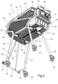
Figure 2 is a lower perspective view of the shopping trolley ofFigure 1 ; -
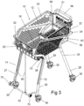
Figure 3 is a second upper perspective view of the shopping trolley ofFigure 1 ; -
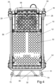
Figure 4 is a top view of the shopping trolley ofFigure 1 ; -
Figure 5 is a bottom view of the shopping trolley ofFigure 1 ; -
Figure 6 is a front view of the shopping trolley ofFigure 1 ; -
Figure 7 is a side view of the shopping trolley ofFigure 1 ; -
Figure 8 is an upper perspective view of the shopping trolley ofFigure 1 showing an inner cover member removed; -
Figure 9 shows the front wheel support frame of the shopping trolley partially rotated from the extended position to the collapsed position; -
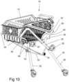
Figure 10 shows a first of the rear legs rotating from the extended position toward the collapsed position; -
Figure 11 shows a second of the rear legs rotating from the extended position toward the collapsed position; -
Figure 12 shows both of the rear legs rotating further toward the collapsed position; -
Figure 13 is an upper perspective view of the shopping trolley showing the front and rear wheel support frames in the collapsed position; -
Figure 14 is a lower perspective view of the shopping trolley in the collapsed position; -
Figure 15 is a second upper perspective view of the shopping trolley in the collapsed position; -
Figure 16 is a top view of the shopping trolley in the collapsed position; -
Figure 17 is a bottom view of the shopping trolley in the collapsed position; -
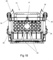
Figure 18 is a front view of the shopping trolley in the collapsed position; -
Figure 19 is a side view of the shopping trolley in the collapsed position; -
Figure 20 is an upper perspective view of the shopping trolley in the collapsed position showing the inner cover member removed; and -
Figure 21 is a side view of the shopping trolley engaging against the rear of a vehicle. - Referring to the Figures, there is shown a
shopping trolley 10 comprising generally abasket 12, first and secondfront legs rear legs basket 12 comprises an open topped receptacle and is formed from abase wall 18, first andsecond end walls second side walls second side walls second end walls base wall 18 to define the open topped receptacle. In the embodiment shown, each of thebase wall 18, the first andsecond side walls second end walls - Each of the first and second
front legs rear legs basket 12 at a first end thereof and includes awheel 30 at a second end thereof. The first ends of the first and secondfront legs rear legs basket 12 such that the front andrear legs Figures 1 to 8 ) and a collapsed position (as shown inFigures 13 to 20 ). In the extended positions, the front andrear legs basket 12 respectively such that theshopping trolley 10 rests on thewheels 30 and may be manoeuvred around in a known manner. - The
front legs front cross member 32 such thatfront legs wheel support frame 14. Thefront cross member 32 extends between the first and secondfront legs - In the embodiment shown, the first and second
rear legs basket 12. In an alternative embodiment however (not shown), the first and secondrear legs - The first and second
front legs first end portion 34 adjacent the first end thereof and asecond end portion 35 extending from thefirst end portion 34 to the second end. Thefirst end portions 34 of the first and secondfront legs basket 12 such that thefirst end portions 34 are located adjacent outer surfaces of the first andsecond side walls first end wall 20. - The first and second
rear legs first end portion 34 adjacent the first end thereof and asecond end portion 35 extending from thefirst end portion 34 to the second end. The first andsecond side walls basket 12 each include a recessedportion 36 adjacent the junction between thebase wall 18 and thesecond end wall 21. Thefirst end portions 34 of therear legs basket 12 within the recessedportions 36 such that the first and secondrear legs second side walls rear legs rear legs front legs - The
first end portions 34 of the first and secondfront legs first end wall 20 in a direction downwardly and rearwardly relative to thebasket 12 when the frontwheel support frame 14 is in the extended position. Thesecond end portions 35 of the first and secondfront legs first end portions 34 in a direction downwardly and forwardly relative to thebasket 12. The first andsecond side walls basket 12 are each provided with awall portion 38 which extends outwardly from the outer surfaces thereof adjacent the junction between thebase wall 18 and thefirst end wall 20. Thewall portions 38 extend from a location above the junction between thebase wall 18 and thefirst end wall 20 to a location located rearwardly of the junction between thebase wall 18 and thefirst end wall 20 such that thefirst end portions 34 of the first and secondfront legs wall portions 38 in the extended position. Thewall portions 38 thereby prevent rotation of the frontwheel support frame 14 beyond the extended position. - The
first end portions 34 of the first and secondrear legs second end wall 21 in a direction downwardly and forwardly relative to thebasket 12 when therear legs second end portions 35 of the first and secondrear legs first end portions 34 in a direction downwardly and rearwardly relative to thebasket 12. The recessedportions 36 in the first andsecond side walls basket 12 each define afirst shoulder portion 40. Thefirst shoulder portion 40 extends from a location located above the junction between thebase wall 18 and thesecond end wall 21 to a location located forwardly of the junction between thebase wall 18 and thesecond end wall 21 such that thefirst end portions 34 of the first and secondrear legs first shoulder portion 40 in the extended position. Thefirst shoulder portions 40 thereby prevent rotation of therear legs - The angle of the
second portions 35 of thefront legs rear legs basket 12 in use will tend to push the front andrear legs rear legs wall portion 38 and thefirst shoulder portion 40. - Outer surfaces of the first and
second side walls basket 12 includesecond shoulder portions 50. Thesecond shoulder portions 50 define a downwardly facing surfaces extending along the first andsecond side walls first end wall 20 to adjacent thesecond end wall 21. The downwardly facing surfaces of thesecond shoulder portions 50 correspond to the shape of the first and secondfront legs front legs second shoulder portion 50 in the collapsed position. In the collapsed position, thewheels 30 of the first and secondfront legs second end wall 21 of thebasket 12. - The
legs first end portions 34 of the first and secondrear legs second side walls second end portions 35 of the first and secondrear legs second side walls Figure 13 . The upper edges of the first andsecond side walls end portions 52 adjacent thefirst end wall 20 such that the recessedend portions 52 receive thewheels 30 of therear legs - The front and
rear legs members 42. The lockingmembers 42 engage with each of the front andrear legs members 42 may be disengaged to allow rotation of the front andrear legs rear wheel legs basket 12. - Each of the locking
members 42 comprises apin 44 mounted with ahousing 46 provided on a lower surface of the base wall 18 (as best seen inFigure 17 ). Each of the front andrear legs corresponding housing 46 having apin 44 mounted on thebase wall 18 adjacent theleg leg - The
pins 44 are spring biased relative to therespective housings 46 such that a distal end of each of thepins 44 is moved outwardly by the spring bias to engage into a hole provided on theadjacent leg legs legs adjacent pins 44 and push thepins 44 inwardly into thehousings 46. When the ends of thepins 44 align with the holes on thelegs pins 44 move into the holes to lock thelegs - The
shopping trolley 10 includes an actuator connected to each of thepins 44 such that operation of the actuator retracts thepins 44 away from thelegs handle 60 mounted adjacent a rear edge of thebase wall 18 of thebasket 12. Thehandle 60 is connected tocables 62 extending along the lower surface of thebasket 12 to thehousings 46. Thecables 62 are connected to thepins 44 such that operation of thehandle 60 causes retraction of thepins 44 inwardly away from thelegs - The front and
rear legs handle 60, thereby allowing thelegs Figures 9 to 13 ). The first and secondfront legs rear legs rear legs rear legs rear legs front cross member 32 as the first and secondfront legs rear legs front cross member 32 in the embodiment shown comprises a U-shaped member extending forwardly of the first and secondfront legs - The
shopping trolley 10 is also provided withsecondary wheels 70 to allow theshopping trolley 10 to be moved around while thelegs secondary wheels 70 is provided on a lower surface of thebase wall 18 of thebasket 12 adjacent thefirst end wall 20. A second pair ofsecondary wheels 70 is provided on thefront cross member 32. The second pair ofsecondary wheels 70 are provided such that the first and second pairs ofsecondary wheels 70 engage with the ground when the front andrear legs shopping trolley 10 may therefore be rolled on thesecondary wheels 70 when thelegs - The
shopping trolley 10 includes one ormore straps 80 extending between thebasket 12 and the frontwheel support frame 14. Thestraps 80 extend between a front end of thebasket 12 such that the straps extend downwardly from thebasket 12 to connect to the frontwheel support frame 14 at a location below thebasket 12. In the embodiment shown, there are provided twosuch straps 80 which have first ends connected to thefirst end wall 20 of thebasket 12 and second ends connected to thefront cross member 32. The first end of thestraps 80 are connected centrally on thefirst end wall 20 of thebasket 12 and the second ends are separated and secured at locations on thefront cross member 32. - The
straps 80 are elasticised and provided to engage with a rear end of a vehicle 11 (as can be seen inFigure 21 ) when the forward end of theshopping trolley 10 is moved towards thevehicle 11. The position of thestraps 80 causes thestraps 80 to engage with the rear end of thevehicle 11 before the frontwheel support frame 14 as can be seen. Engagement between thestraps 80 and thevehicle 11 aids in moving the frontwheel support frame 14 to the collapsed position. When the frontwheel support frame 14 is in the collapsed position, thestraps 80 extend across thebase wall 18 of thebasket 12. The elastic nature of thestraps 80 also acts to pull the frontwheel support frame 14 back to the extended position when unfolding thelegs - The
basket 12 also includes ahandlebar 56. Thehandlebar 56 extends upwardly from the upper edge of thesecond end wall 21 and may be used to move theshopping trolley 10 on either thewheels 30 or thesecondary wheels 70. - An upper surface of the
base wall 18 is provided with a cover member 58 (as can be seen inFigures 8 and20 ). Thecover member 58 is provided to be secured above a portion of thebase wall 18. Thecover member 58 may be secured in a first position (as shown in the Figures) in which theplanar cover member 58 is adjacent and parallel to thebase wall 18 to define a cavity between thecover 58 and thebase wall 18 which may be used to hold personal items. Thecover member 58 may also be removed and attached to thebasket 12 in a second position (not shown), in which theplanar cover member 58 is oriented perpendicular to thebase wall 18. In the second position, thecover member 58 thereby defines a divider within thebasket 12 to divide the interior of thebasket 12 into multiple compartments. - The front and
rear wheel legs front legs rear legs rear legs rear legs front legs rear legs - In use, the
shopping trolley 10 may be used in a supermarket in a known manner to collect items with the front andrear legs rear wheel legs shopping trolley 10 may be rotated to the collapsed positions in order to place theshopping trolley 10 into the rear of avehicle 11. Thehandle 60 is operated and the frontwheel support frame 14 will rotate backwardly towards the collapsed position as thebasket 12 is moved into the rear of the vehicle. Therear legs basket 10. When the front andrear legs legs basket 12. Theshopping trolley 10 therefore provides a relatively compact form which may be easily stored in the rear of a vehicle. - As the
rear legs wheel support frame 16 are located above upper edges of theside walls basket 12 is therefore still easily accessible while thelegs basket 12. When theshopping trolley 10 is to be removed from the car, thelegs basket 12 is pulled from the vehicle. Theshopping trolley 10 may therefore be removed from thecar 11 and wheeled into the home of the consumer for unpacking the purchased items. - Front sides of the
front legs protective strips 72 along portions of the length. The protective strips are provided to protect the rear of thevehicle 11 should thefront legs vehicle 11. - It will be readily apparent to persons skilled in the relevant arts that various modifications and improvements may be made to the foregoing embodiments, in addition to those already described, without departing from the present invention as defined in the claims.
- Prior art document D1
US6045150 discloses an improved collapsible utility cart for use with automobile trunks. As such, the general purpose of the present invention is to provide a new and improved collapsible utility cart for use-with automobile trunks and method which has all the advantages of the prior art and none of the disadvantages. - Prior art document D2
FR2850623 - Prior art document D3
US2016347341 discloses a basket with a lift mechanism that raises the unit to the cargo floor height of the vehicle, and also used to lower the basket to a comfortable working height for the user while shopping. The basket dimensions take into account the space limitations inside the vehicle's cargo area while providing the optimum basket capacity. A slide mechanism includes a frame member, a set of guide rails, a plurality of wheels and rollers to guide the basket and frame assemblies into and out of the vehicle. A plurality of legs and base frame members connected by a plurality of cross members and hinges that are foldable to a compact arrangement and fits in place alongside the basket inside the vehicle. The length of the legs when unfolded should conform to the cargo load height of the vehicle. The legs can be made adjustable in length to compensate for varying cargo load heights of various vehicle makes and models. - Prior art document D4
US2010140887 discloses vehicle loadable cart for loading into a trunk of a vehicle having a floor and a rear wall which is higher than the floor, the cart comprising: a chassis; a retractable main wheel assembly for supporting the chassis when transported over a ground surface; at least one auxiliary wheel assembly with a deployment mechanism that is adapted to shift the auxiliary wheel assembly between a retracted state in which the auxiliary wheel assembly is raised so as to allow the chassis to pass in a substantially horizontal position over the rear wall of the trunk, and a deployed state in which said at least one auxiliary wheel assembly extends downward so as to support the chassis above the trunk floor at an elevation equal to or higher than the rear wall of the trunk, allowing wheeling the cart further into the trunk, whereby when the cart is inside the trunk said at least one auxiliary wheel assembly may be retracted to lower the chassis onto the floor of the trunk. - Prior art document D5
DE102008061318 discloses a shopping cart that allows goods to be quickly reloaded into a vehicle trunk. The invention relates to a trolley with a container supported by a frame, the base of which is provided with wheels. The frame is designed such that the edge of the cart, referred to as the support edge, can be pushed over the floor of a vehicle trunk. The trunk floor thus acts to support the cart and as the frame to is folded and allows the cart to be pushed all the way into the trunk. - Prior art document D6
US2016200340 discloses carriage devices and more particularly a new carriage device for allowing the carriage to be more easily placed within and removed from a vehicle. An embodiment of the disclosure is a cart that has a bottom wall and a peripheral wall extending upwardly therefrom. A top side of the cart is open. The peripheral wall has a front side, a back side, a first lateral side and a second lateral side. The cart may contain a plurality of objects. A handle is attached to the cart. A rolling apparatus is coupled to the cart to facilitate the cart is rolled along a support surface. The rolling apparatus is positionable in a deployed position to elevate the cart a maximum distance above the support surface. The rolling apparatus is positionable in a retracted position to lower the cart to a minimum distance above the support surface. A lock is coupled to the cart and is in mechanical communication with the rolling apparatus. The lock releases the rolling apparatus to facilitate positioning the rolling apparatus between the deployed position and the retracted position.
Claims (15)
- A shopping trolley (10) comprising:a basket (12) having first and second side walls (22 and 23), first and second end walls (20 and 21) and a base wall (18);first and second front legs (26 and 27), each having a wheel (30) on a lower end thereof; andfirst and second rear legs (28 and 29), each having a wheel (30) on a lower end thereof;wherein the first and second front legs (26 and 27) are rotatable from an extended position, in which the first and second front legs (26 and 27) extend downwardly from adjacent a front of the basket (12), to a collapsed position, in which the first and second front legs (26 and 27) are located adjacent outer sides of the first and second side walls (22 and 23) of the basket (12) respectively, and the rear legs (28 and 29) are rotatable from an extended position, in which the first and second rear legs (28 and 29) extend downwardly from adjacent a rear of the basket (12), to a collapsed position, in which portions of the first and second rear legs (28 and 29) are located adjacent and above upper edges of the first and second side walls (22 and 23) of the basket (12) respectively.
- A shopping trolley (10) in accordance with claim 1, wherein the first and second front legs (26 and 27) are rotatably connected to outer surfaces of the side walls (22 and 23) of the basket (12) and the first and second rear legs (28 and 29) are rotatably connected to the basket (12) within recessed portions (36) of the first and second side walls (22 and 23).
- A shopping trolley (10) in accordance with claim 1 or 2, wherein the first and second rear legs (28 and 29) are receivable inside the first and second front legs (26 and 27) as the front legs (26 and 27) move from the extended to the collapsed position.
- A shopping trolley (10) in accordance with claim 3, wherein a front cross member (32) extends between the first and second front legs (26 and 27) such that the front cross member (32) engages the first and second rear legs (28 and 29) as the front legs (26 and 27) move to the collapsed position.
- A shopping trolley (10) in accordance with any one of claims 2 to 4, wherein the first and second front legs (26 and 27) and the first and second rear legs (28 and 29) each include a first end portion (34) adjacent the first end thereof and a second end portion (35) extending from the first end portion (34) to the second end wherein the second portion (35) is at an angle to the first end portion (34) and wherein when the front and rear legs (28 and 29) are in the extended positions, the first end portions (34) of the first and second front legs (26 and 27) are oriented to extend from adjacent the first end wall (20) in a direction downwardly and rearwardly relative to the basket (12), the second end portions (35) of the first and second front legs (26 and 27) extend from the first end portions (34) in a direction downwardly and forwardly relative to the basket (12), the first end portions (34) of the first and second rear legs (28 and 29) are oriented to extend from adjacent the second end wall (20 or 21) in a direction downwardly and forwardly relative to the basket (12) and the second end portions (35) of the first and second rear legs (28 and 29) extend from the first end portions (34) in a direction downwardly and rearwardly relative to the basket (12).
- A shopping trolley (10) in accordance with claim 5, wherein the first end portions (34) of the first and second front legs (26 and 27) are rotatably connected to the basket (12) on outer surfaces of the first and second side walls (22 and 23) respectively adjacent the first end wall (20) and the first end portions (34) of the rear legs (28 and 29) are rotatably connected to the basket (12) within the recessed portions (36) located adjacent the second end wall (20 or 21).
- A shopping trolley (10) in accordance with claim 6, wherein the first and second side walls (22 and 23) of the basket (12) are each provided with an outwardly extending wall portion (38) extending from a location above the junction between the base wall (18) and the first end wall (20) to a location located rearwardly of the junction between the base wall (18) and the first end wall (20) such that the first end portions (34) of the first and second front legs (26 and 27) rest on upper surfaces of the wall portions (38) in the extended position.
- A shopping trolley (10) in accordance with any one of claims 5 to 7, wherein the recessed portions (36) in the first and second side walls (22 and 23) each define a first shoulder portion (40) extending from a location above the junction between the base wall (18) and the second end wall (20 or 21) to a location forwardly of the junction between the base wall (18) and the second end wall (20 or 21) such that the first end portions (34) of the first and second rear legs (28 and 29) rest under the first shoulder portions (40) in the extended position.
- A shopping trolley (10) in accordance with any one of claims 5 to 8 wherein, in the collapsed position, the first end portions (34) of the first and second rear legs (28 and 29) are located adjacent rear edges of the first and second side walls (22 and 23) and the second end portions (35) of the first and second rear legs (28 and 29) are located adjacent and above upper edges of the first and second side walls (22 and 23), the upper edges of the first and second side walls (22 and 23) each including a recessed end portion (52) adjacent the first end wall (20) such that the recessed end portions (52) receive the wheels (70) of the first and second rear legs (28 and 29) in the collapsed position.
- A shopping trolley (10) in accordance with any one of claims 5 to 9, wherein outer surfaces of the first and second side walls (22 and 23) of the basket (12) include second shoulder portions (50) defining downwardly facing surfaces extending along the first and second side walls (22 and 23) from adjacent the first end wall (20) to adjacent the second end wall (20 or 21), the downwardly facing surfaces of the second shoulder portions (50) corresponding to the shape of the first and second front legs (26 and 27) such that the first and second front legs (26 and 27) engage against the downwardly facing surfaces of the second shoulder portions (50) in the collapsed position.
- A shopping trolley (10) in accordance with any one of the preceding claims, wherein the front and rear legs (28 and 29) are maintained in the extended positions by locking members and the locking members extend outwardly from the first and second side walls (22 and 23) to engage with each of the front and rear legs (28 and 29) to restrict rotation of the front and rear wheel support frames (14) away from the extended position.
- A shopping trolley (10) in accordance with claim 11, wherein the locking members each comprise a pin mounted with a housing (46) provided on a lower surface of the base wall (18) such that each of the pins (44) is extendible outwardly from the base wall (18) to engage into a hole in one of the front or rear legs (28 and 29), the pins (44) being spring biased relative to the respective housings (46) such that a distal end of each of the pins (44) is moved outwardly by the spring bias to engage into the hole
- A shopping trolley (10) in accordance with claim 12, wherein an actuator is connected to each of the pins (44) such that operation of the actuator retracts the pins (44) away from the legs to release the front and rear wheel support frames (14) to rotate towards the collapsed position, the actuator comprising a handle (60) mounted adjacent a rear edge of the base wall (18) of the basket (12) connected via cables to the housings (46) such that operation of the handle (60) causes retraction of the pins (44).
- A shopping trolley (10) in accordance with any one of the preceding claims, wherein secondary wheels (70) are provided on which the shopping trolley (10) may be moved when front and rear support frames (14) are in the collapsed position, the secondary wheels (70) comprising a first pair of secondary wheels (70) provided on a lower surface of the base wall (18) of the basket (12) adjacent the first end wall (20) and a second pair of secondary wheels (70) provided on the front cross member (32) extending between the first and second front legs (26 and 27).
- A shopping trolley (10) in accordance with claim 14, wherein one or more straps (80) is provided extending from a front end of the basked (12) to the front wheel support frame such that the straps (80) engage with a rear of a vehicle before the front wheel support frame, the straps (80) having first ends connected to a first end wall (20) of the basked (12) and second ends connected to the front cross member (32) extending between the first and second front legs (26 and 27).
Applications Claiming Priority (5)
| Application Number | Priority Date | Filing Date | Title |
|---|---|---|---|
| AU2018904492A AU2018904492A0 (en) | 2018-11-26 | Shopping Trolley | |
| AU2018904510A AU2018904510A0 (en) | 2018-11-27 | Shopping Trolley | |
| AU2019901845A AU2019901845A0 (en) | 2019-05-29 | Shopping Trolley | |
| AU2019903768A AU2019903768A0 (en) | 2019-10-07 | Shopping Trolley | |
| PCT/AU2019/051287 WO2020107061A1 (en) | 2018-11-26 | 2019-11-22 | Shopping trolley |
Publications (4)
| Publication Number | Publication Date |
|---|---|
| EP3880537A1 EP3880537A1 (en) | 2021-09-22 |
| EP3880537A4 EP3880537A4 (en) | 2022-08-10 |
| EP3880537B1 true EP3880537B1 (en) | 2025-02-12 |
| EP3880537C0 EP3880537C0 (en) | 2025-02-12 |
Family
ID=70852467
Family Applications (1)
| Application Number | Title | Priority Date | Filing Date |
|---|---|---|---|
| EP19888378.7A Active EP3880537B1 (en) | 2018-11-26 | 2019-11-22 | Shopping trolley |
Country Status (11)
| Country | Link |
|---|---|
| US (1) | US11447167B2 (en) |
| EP (1) | EP3880537B1 (en) |
| JP (1) | JP7418850B2 (en) |
| CN (1) | CN112996709A (en) |
| AU (1) | AU2019388264B2 (en) |
| CA (1) | CA3120245A1 (en) |
| IL (1) | IL283378A (en) |
| MX (1) | MX2021006195A (en) |
| SG (1) | SG11202105141XA (en) |
| WO (1) | WO2020107061A1 (en) |
| ZA (1) | ZA202104147B (en) |
Families Citing this family (5)
| Publication number | Priority date | Publication date | Assignee | Title |
|---|---|---|---|---|
| US11919558B2 (en) * | 2019-10-08 | 2024-03-05 | Tammy WHITLEY | Shopping trolley |
| US11603123B1 (en) * | 2020-12-09 | 2023-03-14 | Dario A. Collado | Collapsible shopping cart |
| KR20230031068A (en) * | 2021-08-26 | 2023-03-07 | 현대자동차주식회사 | Folding cart for loading vehicle |
| US11780484B2 (en) * | 2021-11-25 | 2023-10-10 | Compass Carts LLC | Utility cart and transport system |
| KR102715256B1 (en) * | 2022-12-13 | 2024-10-11 | 현대모비스 주식회사 | Battery desorption apparatus for vehicle |
Family Cites Families (13)
| Publication number | Priority date | Publication date | Assignee | Title |
|---|---|---|---|---|
| DE19611542A1 (en) * | 1996-03-23 | 1997-09-25 | Daimler Benz Ag | Transport device as collapsible shopping trolley for car boots |
| US6045150A (en) | 1998-04-21 | 2000-04-04 | Al-Toukhi; Mazen | Collapsible utility cart for use with automobile trunks |
| FR2850623A1 (en) * | 2003-02-03 | 2004-08-06 | Alain Navelier | Basket trolley for shopping in supermarket, has four supports that is fixed at front and back side of basket for maintaining lock and base in position, where base rotates around axis after unlocking it |
| FR2925448B1 (en) | 2007-12-20 | 2010-04-23 | Heuliez | FOLDING SUPERMARKET TROLLEY FOR CAR BOX |
| US20100140887A1 (en) * | 2008-12-10 | 2010-06-10 | Natan Yehiav | Vehicle loadable cart |
| US8333404B2 (en) * | 2010-01-11 | 2012-12-18 | Chaim Moster | Shopping cart with assembly for vehicle storage |
| CN201685842U (en) * | 2010-05-21 | 2010-12-29 | 郑世平 | Foldable cart |
| US9399476B1 (en) * | 2015-01-08 | 2016-07-26 | Diane Stankevitz | Carriage assembly |
| US9573610B1 (en) * | 2015-04-03 | 2017-02-21 | Trunkfit, Llc. | Collapsible trunk-accessible carts |
| IL239086A0 (en) * | 2015-05-28 | 2015-10-29 | Robert Tauber Asher | Shopping cart and method for inserting thereof into a vehicle |
| EP3344513A4 (en) * | 2015-09-01 | 2019-05-08 | Geffen, Yuval | Collapsible locomotion platform and cart |
| US10232867B1 (en) * | 2016-06-21 | 2019-03-19 | Carey Jones | Multi-functional vehicle caddy and associated use thereof |
| WO2018017102A1 (en) * | 2016-07-21 | 2018-01-25 | Ford Global Technologies, Llc | Automatically deployable vehicle carts |
-
2019
- 2019-11-22 SG SG11202105141XA patent/SG11202105141XA/en unknown
- 2019-11-22 JP JP2021528857A patent/JP7418850B2/en active Active
- 2019-11-22 MX MX2021006195A patent/MX2021006195A/en unknown
- 2019-11-22 EP EP19888378.7A patent/EP3880537B1/en active Active
- 2019-11-22 US US17/297,399 patent/US11447167B2/en active Active
- 2019-11-22 AU AU2019388264A patent/AU2019388264B2/en active Active
- 2019-11-22 WO PCT/AU2019/051287 patent/WO2020107061A1/en not_active Ceased
- 2019-11-22 CN CN201980070465.5A patent/CN112996709A/en active Pending
- 2019-11-22 CA CA3120245A patent/CA3120245A1/en active Pending
-
2021
- 2021-05-23 IL IL283378A patent/IL283378A/en unknown
- 2021-06-17 ZA ZA2021/04147A patent/ZA202104147B/en unknown
Also Published As
| Publication number | Publication date |
|---|---|
| EP3880537A4 (en) | 2022-08-10 |
| ZA202104147B (en) | 2022-02-23 |
| US11447167B2 (en) | 2022-09-20 |
| JP2022507885A (en) | 2022-01-18 |
| AU2019388264B2 (en) | 2025-09-18 |
| IL283378A (en) | 2021-07-29 |
| SG11202105141XA (en) | 2021-06-29 |
| AU2019388264A1 (en) | 2021-07-08 |
| CA3120245A1 (en) | 2020-06-04 |
| CN112996709A (en) | 2021-06-18 |
| US20220032984A1 (en) | 2022-02-03 |
| EP3880537A1 (en) | 2021-09-22 |
| EP3880537C0 (en) | 2025-02-12 |
| MX2021006195A (en) | 2021-06-30 |
| JP7418850B2 (en) | 2024-01-22 |
| WO2020107061A1 (en) | 2020-06-04 |
Similar Documents
| Publication | Publication Date | Title |
|---|---|---|
| EP3030472B1 (en) | Foldable shopping cart | |
| US5431263A (en) | Mobile carry-on suitcase | |
| US5645146A (en) | Suitcase with retractable pull handle | |
| US7997591B2 (en) | Chassis with retractable wheels | |
| US11447167B2 (en) | Shopping trolley | |
| US8757643B2 (en) | Retractable wheel assembly | |
| US10238195B2 (en) | Luggage apparatus | |
| CN107207066B (en) | Luggage case | |
| US9351550B2 (en) | Wheel deployment apparatus | |
| CN100448726C (en) | shopping trolley | |
| US20200223465A1 (en) | Collapsible locomotion platform and cart | |
| US8439374B1 (en) | Lightweight high load capacity folding utility cart with unique support structure and ergonomic handle | |
| US20100230934A1 (en) | Cart | |
| US10293737B2 (en) | Modular trunk system | |
| US20150342318A1 (en) | Wheeled assembly | |
| US11919558B2 (en) | Shopping trolley | |
| US20040000458A1 (en) | Baggage cart suitcase | |
| WO1998008721A1 (en) | Suitcase and cart assembly | |
| EP3558790A1 (en) | Trolley with vehicle storage device | |
| US11825925B2 (en) | Luggage comprising two sections foldable between a deployed use configuration and a folded storage configuration | |
| JP2000302044A (en) | Hand cart and basket used for it | |
| CA2833071A1 (en) | Retractable wheel assembly |
Legal Events
| Date | Code | Title | Description |
|---|---|---|---|
| STAA | Information on the status of an ep patent application or granted ep patent |
Free format text: STATUS: THE INTERNATIONAL PUBLICATION HAS BEEN MADE |
|
| PUAI | Public reference made under article 153(3) epc to a published international application that has entered the european phase |
Free format text: ORIGINAL CODE: 0009012 |
|
| STAA | Information on the status of an ep patent application or granted ep patent |
Free format text: STATUS: REQUEST FOR EXAMINATION WAS MADE |
|
| 17P | Request for examination filed |
Effective date: 20210618 |
|
| AK | Designated contracting states |
Kind code of ref document: A1 Designated state(s): AL AT BE BG CH CY CZ DE DK EE ES FI FR GB GR HR HU IE IS IT LI LT LU LV MC MK MT NL NO PL PT RO RS SE SI SK SM TR |
|
| DAV | Request for validation of the european patent (deleted) | ||
| DAX | Request for extension of the european patent (deleted) | ||
| A4 | Supplementary search report drawn up and despatched |
Effective date: 20220708 |
|
| RIC1 | Information provided on ipc code assigned before grant |
Ipc: B62B 5/00 20060101ALI20220704BHEP Ipc: B62B 3/02 20060101AFI20220704BHEP |
|
| GRAP | Despatch of communication of intention to grant a patent |
Free format text: ORIGINAL CODE: EPIDOSNIGR1 |
|
| STAA | Information on the status of an ep patent application or granted ep patent |
Free format text: STATUS: GRANT OF PATENT IS INTENDED |
|
| RIC1 | Information provided on ipc code assigned before grant |
Ipc: B62B 5/00 20060101ALI20240628BHEP Ipc: B62B 3/02 20060101AFI20240628BHEP |
|
| INTG | Intention to grant announced |
Effective date: 20240723 |
|
| GRAJ | Information related to disapproval of communication of intention to grant by the applicant or resumption of examination proceedings by the epo deleted |
Free format text: ORIGINAL CODE: EPIDOSDIGR1 |
|
| STAA | Information on the status of an ep patent application or granted ep patent |
Free format text: STATUS: REQUEST FOR EXAMINATION WAS MADE |
|
| GRAP | Despatch of communication of intention to grant a patent |
Free format text: ORIGINAL CODE: EPIDOSNIGR1 |
|
| STAA | Information on the status of an ep patent application or granted ep patent |
Free format text: STATUS: GRANT OF PATENT IS INTENDED |
|
| GRAS | Grant fee paid |
Free format text: ORIGINAL CODE: EPIDOSNIGR3 |
|
| INTC | Intention to grant announced (deleted) | ||
| GRAA | (expected) grant |
Free format text: ORIGINAL CODE: 0009210 |
|
| STAA | Information on the status of an ep patent application or granted ep patent |
Free format text: STATUS: THE PATENT HAS BEEN GRANTED |
|
| INTG | Intention to grant announced |
Effective date: 20241211 |
|
| AK | Designated contracting states |
Kind code of ref document: B1 Designated state(s): AL AT BE BG CH CY CZ DE DK EE ES FI FR GB GR HR HU IE IS IT LI LT LU LV MC MK MT NL NO PL PT RO RS SE SI SK SM TR |
|
| REG | Reference to a national code |
Ref country code: GB Ref legal event code: FG4D |
|
| REG | Reference to a national code |
Ref country code: CH Ref legal event code: EP |
|
| REG | Reference to a national code |
Ref country code: DE Ref legal event code: R096 Ref document number: 602019065943 Country of ref document: DE |
|
| REG | Reference to a national code |
Ref country code: IE Ref legal event code: FG4D |
|
| U01 | Request for unitary effect filed |
Effective date: 20250307 |
|
| U07 | Unitary effect registered |
Designated state(s): AT BE BG DE DK EE FI FR IT LT LU LV MT NL PT RO SE SI Effective date: 20250314 |
|
| PG25 | Lapsed in a contracting state [announced via postgrant information from national office to epo] |
Ref country code: RS Free format text: LAPSE BECAUSE OF FAILURE TO SUBMIT A TRANSLATION OF THE DESCRIPTION OR TO PAY THE FEE WITHIN THE PRESCRIBED TIME-LIMIT Effective date: 20250512 |
|
| PG25 | Lapsed in a contracting state [announced via postgrant information from national office to epo] |
Ref country code: PL Free format text: LAPSE BECAUSE OF FAILURE TO SUBMIT A TRANSLATION OF THE DESCRIPTION OR TO PAY THE FEE WITHIN THE PRESCRIBED TIME-LIMIT Effective date: 20250212 |
|
| PG25 | Lapsed in a contracting state [announced via postgrant information from national office to epo] |
Ref country code: ES Free format text: LAPSE BECAUSE OF FAILURE TO SUBMIT A TRANSLATION OF THE DESCRIPTION OR TO PAY THE FEE WITHIN THE PRESCRIBED TIME-LIMIT Effective date: 20250212 |
|
| PG25 | Lapsed in a contracting state [announced via postgrant information from national office to epo] |
Ref country code: IS Free format text: LAPSE BECAUSE OF FAILURE TO SUBMIT A TRANSLATION OF THE DESCRIPTION OR TO PAY THE FEE WITHIN THE PRESCRIBED TIME-LIMIT Effective date: 20250612 Ref country code: NO Free format text: LAPSE BECAUSE OF FAILURE TO SUBMIT A TRANSLATION OF THE DESCRIPTION OR TO PAY THE FEE WITHIN THE PRESCRIBED TIME-LIMIT Effective date: 20250512 |
|
| PG25 | Lapsed in a contracting state [announced via postgrant information from national office to epo] |
Ref country code: HR Free format text: LAPSE BECAUSE OF FAILURE TO SUBMIT A TRANSLATION OF THE DESCRIPTION OR TO PAY THE FEE WITHIN THE PRESCRIBED TIME-LIMIT Effective date: 20250212 |
|
| PG25 | Lapsed in a contracting state [announced via postgrant information from national office to epo] |
Ref country code: GR Free format text: LAPSE BECAUSE OF FAILURE TO SUBMIT A TRANSLATION OF THE DESCRIPTION OR TO PAY THE FEE WITHIN THE PRESCRIBED TIME-LIMIT Effective date: 20250513 |
|
| PG25 | Lapsed in a contracting state [announced via postgrant information from national office to epo] |
Ref country code: SM Free format text: LAPSE BECAUSE OF FAILURE TO SUBMIT A TRANSLATION OF THE DESCRIPTION OR TO PAY THE FEE WITHIN THE PRESCRIBED TIME-LIMIT Effective date: 20250212 |
|
| PG25 | Lapsed in a contracting state [announced via postgrant information from national office to epo] |
Ref country code: CZ Free format text: LAPSE BECAUSE OF FAILURE TO SUBMIT A TRANSLATION OF THE DESCRIPTION OR TO PAY THE FEE WITHIN THE PRESCRIBED TIME-LIMIT Effective date: 20250212 |
|
| PG25 | Lapsed in a contracting state [announced via postgrant information from national office to epo] |
Ref country code: SK Free format text: LAPSE BECAUSE OF FAILURE TO SUBMIT A TRANSLATION OF THE DESCRIPTION OR TO PAY THE FEE WITHIN THE PRESCRIBED TIME-LIMIT Effective date: 20250212 |
|
| PLBE | No opposition filed within time limit |
Free format text: ORIGINAL CODE: 0009261 |
|
| STAA | Information on the status of an ep patent application or granted ep patent |
Free format text: STATUS: NO OPPOSITION FILED WITHIN TIME LIMIT |
|
| 26N | No opposition filed |
Effective date: 20251113 |