EP3879498B1 - Verfahren zum rendern eines volumens und einer in dem volumen eingebetteten oberfläche - Google Patents
Verfahren zum rendern eines volumens und einer in dem volumen eingebetteten oberfläche Download PDFInfo
- Publication number
- EP3879498B1 EP3879498B1 EP20161937.6A EP20161937A EP3879498B1 EP 3879498 B1 EP3879498 B1 EP 3879498B1 EP 20161937 A EP20161937 A EP 20161937A EP 3879498 B1 EP3879498 B1 EP 3879498B1
- Authority
- EP
- European Patent Office
- Prior art keywords
- rendering
- volume
- depth
- fragment
- depths
- Prior art date
- Legal status (The legal status is an assumption and is not a legal conclusion. Google has not performed a legal analysis and makes no representation as to the accuracy of the status listed.)
- Active
Links
Images


Classifications
-
- G—PHYSICS
- G06—COMPUTING OR CALCULATING; COUNTING
- G06T—IMAGE DATA PROCESSING OR GENERATION, IN GENERAL
- G06T15/00—3D [Three Dimensional] image rendering
- G06T15/005—General purpose rendering architectures
-
- G—PHYSICS
- G06—COMPUTING OR CALCULATING; COUNTING
- G06T—IMAGE DATA PROCESSING OR GENERATION, IN GENERAL
- G06T15/00—3D [Three Dimensional] image rendering
- G06T15/08—Volume rendering
-
- G—PHYSICS
- G06—COMPUTING OR CALCULATING; COUNTING
- G06T—IMAGE DATA PROCESSING OR GENERATION, IN GENERAL
- G06T15/00—3D [Three Dimensional] image rendering
- G06T15/04—Texture mapping
-
- G—PHYSICS
- G06—COMPUTING OR CALCULATING; COUNTING
- G06T—IMAGE DATA PROCESSING OR GENERATION, IN GENERAL
- G06T15/00—3D [Three Dimensional] image rendering
- G06T15/06—Ray-tracing
-
- G—PHYSICS
- G06—COMPUTING OR CALCULATING; COUNTING
- G06T—IMAGE DATA PROCESSING OR GENERATION, IN GENERAL
- G06T15/00—3D [Three Dimensional] image rendering
- G06T15/10—Geometric effects
- G06T15/30—Clipping
-
- G—PHYSICS
- G06—COMPUTING OR CALCULATING; COUNTING
- G06T—IMAGE DATA PROCESSING OR GENERATION, IN GENERAL
- G06T15/00—3D [Three Dimensional] image rendering
- G06T15/50—Lighting effects
- G06T15/80—Shading
-
- G—PHYSICS
- G06—COMPUTING OR CALCULATING; COUNTING
- G06T—IMAGE DATA PROCESSING OR GENERATION, IN GENERAL
- G06T7/00—Image analysis
- G06T7/50—Depth or shape recovery
-
- G—PHYSICS
- G06—COMPUTING OR CALCULATING; COUNTING
- G06T—IMAGE DATA PROCESSING OR GENERATION, IN GENERAL
- G06T2210/00—Indexing scheme for image generation or computer graphics
- G06T2210/41—Medical
Definitions
- the present invention relates to a computer-based method of rendering a volume and a surface embedded in the volume.
- Computer-based visualizations of datasets representing a volume may be generated using techniques generally known as rendering.
- Rendering may, for example, be used to visualize the results of a medical imaging process, such as a CT scanning process or the like.
- rendering may allow for a radiologist, a surgeon or a therapist to visualize and thereby understand and interpret data representing anatomy.
- Providing a visualization of such data may, for example, be used for diagnosis, teaching, patient communication etc.
- Visualization of volume data is also applied in numerous other technical fields, for example in geological, industrial quality assurance and scientific simulations.
- an added surface may be visualized that is partially or fully embedded in a volumetric dataset.
- a surface may be rendered representing a model of an object such as a medical tool or implant in the scan volume of a patient or a segmentation of an organ of the patient.
- one or more non-physical objects such as landmarks or labels may be rendered in the volume. Similar circumstances may also arise in a variety of other fields dealing with 3D data, including CAD, CFD, and manufacturing.
- Visualizations of volumetric datasets may be rendered with an added surface, for example in a medical visualization workflow.
- a medical tool may be visualized to simulate a surgical operation on the patient, or it may be desirable to visualise surfaces used to label parts of the anatomy of the patient.
- Such objects may be modelled by use of a surface which may be embedded in the volumetric dataset which represents the anatomy of the patient.
- One way of handling rendering of both volume and surface data is to use a rasterization technique to render the surface and to query a depth buffer obtained from the rasterization during computation of the volume rendering integral. For example, traversal of a ray during the computation of the rendering integral may be stopped at the depth specified by the surface rendering depth buffer. The resulting rendered volume may then be composited over the rendering of the surface produced by the rasterization technique.
- Such methods may require re-rendering of the volume each time a change, e.g. in position, is made to the surface. This can be computationally expensive, particularly where a physically based rendering technique such as Monte Carlo path tracing is used to render the volume.
- the visualization of the surface may be obtrusive and may undesirably occlude portions of the volume.
- a segmentation surface of the liver may obscure internal vessels or lesions represented by the volumetric data.
- the surface may be visualized as a semi-transparent solid surface. This allows internal structures to be visualized.
- the handling of multiple semi-transparent surfaces may require complex depth merging techniques, such as depth peeling and variants thereof.
- Non-patent document " Fast re-rendering of volume and surface graphics by depth, color, and opacity buffering" (Bhalerao A. et al, Medical Image Analysis, Oxford University Press, Oxford, GB, vol. 4, no. 3, September 2000 ) describes a method for quickly re-rending volume data consisting of several distinct materials and intermixed with moving geometry. The method works by storing, to a given approximation, depth, color and opacity information, which facilitates accelerated rendering of fixed views at moderate storage overhead without re-scanning the entire volume.
- Non-patent document " Intermixing Surface And Volume Rendering” (Kaufman A. Et Al, NATO ASI Series, Springer Verlag, Berlin, DE, vol. 60, June 1990 ) describes approaches for intermixing geometric models with sample 3D medical data, including a hybrid approach that employs a Z-merging algorithm.
- EP3462418A1 describes a method of rendering one or more material properties of a surface of an object. The method involves acquiring a medical dataset representing the object and rendering, by a physically based volumetric renderer and from the medical dataset, one or more material properties of the surface of the object, at each of a plurality of rendering locations.
- a computer-implemented method for rendering a volumetric dataset and a surface embedded in the volumetric dataset comprising: performing a volume rendering process to generate a volume rendering of a volumetric dataset; determining, based on the volume rendering process, depths of respective locations in the volume rendering and storing the depths in association with the respective locations; performing a surface rendering process to generate a surface rendering of a surface, the surface rendering process comprising using the depths and respective locations; and combining the volume rendering and the surface rendering into a combined rendering of the volume and the surface.
- the determining the depths of the respective locations in the volume rendering comprises using a ray casting process to obtain initial values for the depths, by: casting a plurality of rays through the volumetric dataset, each ray being associated with a location of the respective locations; determining, along each of the rays, at least one depth value associated with a predetermined change in a value related to the volumetric dataset, and storing the at least one depth values in a data structure; and selecting, according to predetermined criteria, a pre-determined number of the at least one depth values at each respective location to be used as initial values for the depths at each of the respective locations determining respective initial depths using a ray casting process.
- the determining the depths of the respective locations in the volume rendering also comprises modifying the initial values for the depths during the volume rendering process using data of scattering locations obtained from a physically based rendering process.
- the locations may correspond with pixel locations in the volume rendering.
- the surface rendering process may comprise, based on a comparison of a depth of a fragment of the surface with a depth stored in association with a location associated with the fragment of the surface, clipping the fragment of the surface from the surface rendering.
- the surface rendering process may comprise, based on a comparison of a depth of a fragment of the surface with a depth stored in association with a location associated with the fragment of the surface, selecting a rendering style or parameter for use in rendering the fragment by the surface rendering process.
- the volume rendering process may comprise a physically based rendering process and the depths may be obtained by sampling paths traced during the physically based rendering process.
- the depths may be obtained by determining, for each pixel in the volume rendering, an average depth value from a plurality of paths sampled to render the pixel by the physically based rendering process.
- Determining the depths may comprise determining, for at least some of the respective locations in the volume rendering, a plurality of depths per location and storing each of the plurality of depths in association with a location of the locations.
- the method may comprise selecting, for a given fragment of the surface, a surface rendering style or parameter for use in the surface rendering process used to render the fragment based on a comparison of a depth of the fragment with a depth of the depths at a location in the volume rendering associated with the fragment.
- the method may comprise selecting, for the fragment, the surface rendering style or parameter for use in the surface rendering process used to render the fragment based on whether the comparison of the depth of the fragment with the depth at the location in the volume rendering associated with the fragment indicates that the fragment is occluded by or is not occluded by an object in the volumetric dataset.
- the method may comprise selecting, for a given fragment of the surface, a surface rendering style or parameter for use in the surface rendering process used to render the fragment based on whether a comparison of a depth associated with the fragment with a depth of the depths at a location associated with the fragment indicates that the fragment is in front of, inside or behind an object in the volumetric dataset.
- a set of machine-readable instructions which when executed by a processor cause a method according to the first aspect to be performed.
- a machine-readable medium comprising a set of machine-readable instructions according to the second aspect.
- apparatus comprising a processor and a storage comprising a set of machine-readable instructions which when executed by the processor cause the processor to perform a method according to the first aspect.
- a computer-implemented method for rendering a volumetric dataset and a surface embedded in the volumetric dataset comprising: determining depths of the surface at respective locations with respect to a viewing point to be used to render the volumetric dataset and storing the depths in association with the respective locations; performing a volume rendering process to render the volumetric dataset, the volume rendering process comprising applying a shading process using the depths of the surface and the respective locations.
- the shading process may comprise a modification process to modify one or more optical properties of a first point in the volumetric dataset based on a comparison of a depth of the first point with a depth of the surface stored in association with a location associated with the first point.
- the modification process may be based on one or more properties of a fragment of the surface having the depth stored in association with the location associated with the first point.
- the one or more properties of the fragment of the surface may comprise a colour and/or an opacity and/or a normal direction.
- Modifying the one or more optical properties of the first point may comprise performing a blending process to obtain a modified colour for the first point based on a colour of the first point and a colour of the fragment of the surface.
- Modifying the one or more optical properties of the first point may comprise determining one or more parameters of the blending process based on a property of the fragment of the surface.
- the property of the fragment of the surface may, for example, be a property indicating that the fragment of the surface is at an edge of the surface.
- the method according to the first further aspect of the present disclosure may comprise performing a surface rendering process to produce a surface rendering of the surface.
- the surface rendering process may comprise the determining of the depths of the surface.
- the surface rendering process may comprise a rasterization-based process.
- the determining the depths of the surface at the respective locations may comprise performing a depth peeling process.
- the determining the depths of the surface at the respective locations may comprise generating a fragment linked list.
- Generating a fragment linked list may comprise generating a k + -buffer.
- the surface rendering process may comprise rasterizing the surface for deferred shading during the volume rendering process, and, for example, computing one or more G-buffers for one or more depth layers defined by the surface.
- the volume rendering process may comprise a ray casting process or a path tracing process.
- the shading process may comprise computing shading for points along each of one or more rays cast during the ray casting process or along each of one or more primary rays used during the path tracing process.
- Determining the depths of the surface at the respective locations may comprise determining, for at least some of the respective locations, a plurality of depths per location and storing each of the plurality of depths in association with a location of the locations.
- a set of machine-readable instructions which when executed by a processor cause a method according to the first further aspect of the present disclosure to be performed.
- a machine-readable medium comprising a set of machine-readable instructions according to the second further aspect of the present disclosure.
- apparatus comprising a processor and a storage comprising a set of machine-readable instructions which when executed by the processor cause the processor to perform a method according to the first further aspect of the present disclosure.
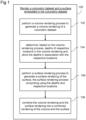
- Figure 1 illustrates a flow chart representation of an example method 100 of generating a computer-based representation of a volumetric dataset and a surface embedded in the volumetric dataset.
- the method 100 comprises, at block 102, performing a volume rendering process to generate a volume rendering of the volumetric dataset.
- the volumetric dataset may comprise a plurality of voxels.
- Various volume data reconstruction filters may be used during rendering, e.g. nearest neighbour, trilinear or higher-order filters such as the B-spline filter.
- the filter may be interpolating or not. Where the filter is not interpolating, over-smoothing may be used as part of the rendering.
- data filtering may be applied separately from the rendering process.
- the data filtering may comprise, e.g., gaussian smoothing, unsharp masking, thresholding and various morphological operations.
- the method comprises determining, based on the volume rendering process, depths of respective locations in the volume rendering and storing the depths in association with the respective locations.
- the volume rendering process may, for example, comprise a physically based rendering process, such as Monte Carlo path tracing.
- the depths may be obtained from tracing paths during the path tracing process.
- depth data corresponding to stochastic light scattering events sampled during the path tracing process may be used to obtain depth data for locations associated with the scattering events.
- Each of the respective locations may correspond with a pixel in the volume rendering. Determining the depths and respective locations may comprise determining what may be referred to herein as a "depth image".
- a depth image comprises the per-pixel distance between the viewing camera and 3D structures in the volume data. The depth image may be considered conceptually similar to the output of a modern RGBD camera.
- Selecting the 3D structure in the volume data which provides the distance to be stored as the depth for a given pixel may comprise use of a heuristic. For example, using one particular heuristic may comprise determining the first time the optical opacity along a ray associated with a given pixel is above a certain threshold and labelling the voxel location, i.e. the 3D location in the volumetric dataset represented by the voxel, at which this occurs as 'solid' and using the voxel location for depth image generation.
- the depth for a given pixel may be obtained by determining an average depth value at which a plurality of paths traced for the given pixel are scattered. For example, a depth may be determined by determining an average or median depth value at which a plurality of paths traced for the given pixel are scattered.
- a machine-learning-based heuristic may be applied to compute a depth value for a given pixel based on data gathered from a plurality of paths which are traced.
- the volume rendering process may comprise a direct volume rendering process such as ray casting.
- determining the depths of the respective locations in the volume rendering comprises using a ray casting volume rendering process to obtain one or more initial depth values for each respective location.
- the initial values may be modified or refined during volume rendering, for example, by use of depth data obtained during a path tracing process. This will be described below in more detail.
- a plurality of depths may be obtained for each pixel in the rendering or for at least some of the pixels in the rendering.
- Each of the plurality of depths may be stored in association with the respective pixel.
- a plurality of depth layers may be defined for the volume rendering, which may be referred to as depth images.
- the method comprises performing a surface rendering process to generate a surface rendering of the surface.
- Generating the surface rendering comprises using the depths and respective locations, e.g. depths corresponding with respective pixels in the image being rendered, obtained from the volume rendering process.
- the surface rendering process may comprise rasterization.
- the surface may be a mesh or the like, as will be described below in more detail.
- the depths obtained from the volume rendering may be used to clip fragments of the surface during the surface rendering. For example, a fragment of the surface may be clipped from a rasterization, based on a comparison of a depth of the volume rendering at a location associated with the surface fragment.
- a comparison of a depth associated with the surface fragment with the depth of the volume rendering at a respective location, e.g. pixel, associated with the fragment may indicate that the surface fragment is occluded by an object in the volume.
- the occluded fragment may be clipped from the rasterized image so that it is not visible in the final combined image.
- a rendering style or a parameter for use in the surface rendering may be selected for a given surface fragment based on whether the surface fragment is occluded or is not occluded by the volume data. Examples of this are described below in more detail.
- the surface rendering style or the parameters thereof applied to a given surface fragment may depend on a comparison of a depth associated with the fragment with one or more depths of the volume rendering at the respective location associated with the fragment. This may, for example where two depth images are used, allow a different rendering style to be applied to a surface fragment based on whether the comparison indicates that the surface fragment lies in front of, inside, or behind an object in the volume.
- the plurality of depths may, for example, include depths for different parts of the anatomy per pixel, e.g. a depth may correspond to a layer of skin or to bone and to an organ.
- the method comprises combining the volume rendering and the surface rendering into a combined rendering of the volumetric dataset and the surface.
- the volume rendering process may produce a path traced volume rendering and the surface rendering may produce a rasterized surface rendering.
- the rasterization may be overlaid onto the volume rendering.
- the resulting combined rendering may be transmitted to visualization apparatus, to be displayed to a user.
- Example methods described with reference to Figure 1 therefore provide for depth data related to the volumetric dataset to be extracted during the volume rendering process and used in rendering the surface, to embed a rendering of the surface in a rendering of the volumetric dataset.
- the surface may be rendered using a rasterization process during which depth data from the volume renderer may be used to clip portions or fragments of the surface which fall behind the depths extracted from the volume rendering.
- the rendering of the surface produced from the rasterization process may be composited with the volume rendering, e.g. overlaid directly onto the volume rendering, to produce a combined rendering of the volume and the surface. This provides a fast approach for producing a rendering of the surface and the volume.
- example methods described herein allow for the surface data to be updated without restarting rendering of the volume data.
- certain example methods described herein may find application in, for example, live editing of landmarks and/or annotations embedded in the volume as well as, for example, changing the style of visualization used for the surface without re-rendering the volume.
- the visualization of the, e.g. segmentation, surface may be changed between a visualization of the entire surface and a, less intrusive, silhouette rendering of the surface.
- obtaining depth data which relates a position of the surface to be rendered to 3D structures in the volume allows in some examples for different rendering effects to be applied based on whether the surface is occluded or is not occluded by the volume. Examples of this are described in more detail below.
- the volume rendering process for rendering the volume and from which the depth image is obtained may be any suitable volume rendering technique such as path tracing or ray casting, or in some examples a combination of both path tracing and ray casting.
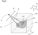
- Figure 2 illustrates schematically a volumetric dataset 200 and surface 250 to be rendered by example methods described herein.
- the volumetric dataset 200 may be referred to herein as the volume 200.
- the volumetric dataset 200 may comprise a discrete sampling of a scalar field.
- the volumetric dataset 200 may comprise a medical dataset.
- a medical dataset may be received by loading from a memory, sensors, and/or other sources.
- Such a medical dataset may represent a part of a patient, for example a human or animal patient.
- any scanning modality which will produce a volumetric dataset may be used to produce the volumetric dataset 200.
- the scanning modality may comprise the use of computed tomography (CT), or of magnetic resonance imaging (MRI).
- CT computed tomography
- MRI magnetic resonance imaging
- a scanning modality comprising the use of positron emission tomography (PET), single photon emission computed tomography (SPECT), ultrasound, or another scan modality may be used.
- PET positron emission tomography
- SPECT single photon emission computed tomography
- ultrasound or another scan modality
- Scan data may be provided in the form of multiple two-dimensional (2D) scans or may be formatted from a scan.
- the volumetric dataset 200 is a DICOM dataset created by scanning at least a portion of a patient using a scanning modality.
- values making up the volumetric dataset 200 may represent geological data (e.g. gathered using seismic data), or as part of industrial quality assurance (e.g. gathered using industrial x-ray scans).
- the volumetric dataset 200 may comprise values representing an object produced via a scientific model rather than measured values representing a physical object.
- a volumetric dataset may comprise data relating to a non-scalar field.
- the volumetric dataset may comprise data relating to a velocity field produced by a fluid simulation.
- the volumetric dataset 200 may comprise data formatted as a plurality of voxels 201.
- the voxels 201 may, for example, be in a uniform or non-uniform grid, or may be arranged in some other type of geometry (e.g., polar coordinate format).
- Each voxel 201 may represent a scalar value, such as scalar value obtained by sampling a scalar field, as described above.
- the type of scalar value represented by each voxel 201 may be dependent on the means by which the volumetric dataset 200 is obtained. For example, where a CT scanner is used to produce the volumetric dataset 200, the dataset may comprise Hounsfield values.
- the volumetric dataset 200 comprises a representation of an object 210, which may be a representation of a portion of a medical patient or the like.
- each voxel 201 in the volume 200 is classified and assigned visual parameter data.
- the visual parameter data assigned to each voxel 201 comprises an opacity and a colour.
- the visual parameter data assigned to each voxel 201 is determined via use of a transfer function, as mentioned in examples above.
- a transfer function may assign visual parameter data to the voxel 201 based on, for example, the scalar value of the voxel 201.
- additional properties related to the voxel 201 may be used an input into a transfer function and therefore may affect the visual parameter data assigned to the voxel 201.
- a transfer function may assign to a given point in the volume 200 one or more of: a scattering coefficient, a specular coefficient, a diffuse coefficient, a scattering distribution function, a bidirectional transmittance distribution function, a bidirectional reflectance distribution function, and colour information. These parameters may be used to derive a transparency, reflectivity, surface roughness, and/or other properties of the surface of the given point. These surface material properties may be derived based on scalar values of the volumetric dataset at the rendering location, and/or based on user-specified parameters.
- Example methods of rendering the volumetric dataset 200 and the surface comprise defining a viewpoint 10 with respect to the volumetric dataset 200.
- a viewing plane 20 is also defined and located in front of the viewpoint 10.
- the viewing plane 20 comprises a number of pixels (not shown in the figures), e.g. arranged in a grid, and allows construction of a visualization of the volumetric dataset 200, as viewed from the viewpoint 10.
- a volume rendering method such as ray casting or a physically based volume rendering method such as path tracing may be employed to render the volume 200.
- Some examples employ both ray casting and path tracing, as described below.
- a sample point may not be coincident with a voxel 201 and, as such, interpolation may be employed to determine a scalar value at that sample point.
- interpolation may be employed to determine a scalar value at that sample point.
- trilinear interpolation or another example method of interpolation, may be performed to determine an interpolated scalar value for a sample point.
- the transfer function may then be applied to the interpolated value of the volumetric dataset 200 at the sample point. It will be appreciated that interpolation may be done before applying a transfer function or the like, or values resulting from application of such a function may themselves be interpolated for use in methods herein.
- a rendering algorithm may model an illumination effect by modelling a light source 50 illuminating the volume 200.
- the illumination effect may be taken into account when accumulating the accumulated opacity and colour values along the ray 30.
- the light source 50 may be a point source, a directional light source, or may comprise a light map.
- the simulation light source may also be any other kind of light source - e.g. a model of any object which emits light - or a combination of multiple different light sources.
- parts of the volumetric dataset itself may emit light.
- the light source may comprise a high definition light map.
- the light map in some examples may have six sides corresponding to outer sides of the volumetric dataset where the volume is cuboidal, for example.
- Ray casting comprises traversing a number of simulated rays 30 through the volumetric dataset 200, wherein each of the rays 30 intersects the viewing plane 20 and the rays 30 are convergent at the viewpoint 10.
- one ray, or more than one ray may be traversed through the volume 200 for each pixel of the viewing plane 20.
- Each ray 30, which is traversed through the volume 200 may allow determination of a value or set of values for display by a pixel of viewing plane 20 which is intersected by that ray 30.
- a rendering algorithm may be employed which determines a value for display by the pixel via a calculation taking into account the path of the ray 30 through the volume 200.
- a colour and brightness for the pixel may be determined via traversing a ray 30 through the volume 200 from the viewpoint 10 and calculating the effect on the ray 30 of accumulated visual parameters of parts of the volume 200 which lie along a path of the ray 30.
- a plurality of sample points within the volumetric dataset 200 along the path of each ray 30 may be selected. Some of these may lie outside points in the object 210 and thus may not contribute to the colour and opacity value for display by the pixel with which the ray 30 is associated.
- Monte Carlo path tracing light propagation through the volume 200 is simulated, including simulating scattering and absorption, by tracing a plurality, for example millions, of simulated light rays.
- Figure 2 also shows the surface 250 embedded in the volume 200.
- the surface 250 represents an object, such as a medical implant or a segmentation surface of an organ.
- one or more surfaces may be provided embedded or partially embedded in the volume 200.
- Surfaces of any shape may be provided, such as a surface modelling an organ, tool, or other object.
- a medical tool that may be inserted into a patient is modelled, such as transoesophageal (TEE) ultrasound probe.
- TEE transoesophageal
- the surface may have a flat, curved, or both flat and curved portions.
- the surface may be open or closed.
- the surface may have any numbers of textures or surface properties (e.g., transparency, dullness, rough, flat, smooth, colour, shininess, or gloss).
- the material of the surface is defined by any number of surface properties, or the material definition (e.g., plastic) indicates the surface properties.
- the surface may be a model representing an object not actually modelled by the volumetric data, but contained in the same patient space, e.g. a CAD model of an implant during an implant placement simulation.
- the surface may be a model representing an object in the patient volume.
- the surface may be a segmentation of an organ.
- the surface is detected from the voxel data and separately quantified or modelled (e.g., a segmented, implicit, or iso-surface).
- an inserted tool e.g., catheter, endoscope, stent, or valve
- the surface of the tool identified by segmentation or other detection.
- any suitable surface model may be used to define the surface.
- the surface is embedded in a structured 3D grid and each voxel corresponding to the surface is flagged or used to define the surface.
- the connected nodes of an unstructured grid define the surface.
- the nodes may be at or may be separate from the voxel locations.
- the surface definition may have the same or a different resolution as the volume or voxel data.
- Voxels may be tagged as "inside” or "outside” in order to represent a closed surface.
- a distance field may be used, where each voxel stores a distance to the surface. The surface is then the iso-surface having a distance to the surface of 0.
- the location of the surface relative to the scanned volume is known or set. Where modelling is used, the location of the surface relative to the volume may be arbitrary or based on detected anatomical structure. Where segmentation of implicit structure is used to find the surface from the voxel data, the location relative to the volume is also determined. The location of the surface relative to the volume may be static or may change over time.
- more than one surface may be of interest.
- the surfaces may be independent of each other, for example having no common or intersecting locations. Alternatively, the surfaces may contact or intersect, but be separately defined. There may be one, two, three, or more surfaces for a given scan volume.
- an acceleration structure may be used to efficiently compute the ray-surface intersection results for use in the surface rendering process. Any suitable acceleration structure for computing ray intersections with the surface/s in a real-time or interactive environment may be used.
- volume rendering techniques such as a physically based rendering process, e.g. Monte Carlo path tracing, may be used to obtain depth values to generate one or more depth images of the volume 200, during volume rendering of the volume 200.
- a combination of depths corresponding to various scattering points obtained during the physically based rendering may be used to obtain depths for different positions in the volume rendering.
- a depth is determined from the Monte Carlo path tracing. For example, a random number generator determines an opacity up to which a ray is to be traced through the volume. Depending on the gradient magnitude at a given location in the volume along the ray, the ray may be scattered by the given location in the volume. The scatter points indicate where the depth may be sampled. Due to the random sampling in physically based volume rendering, different potential depths are considered.
- the scattering occurs at different depths due to the stochastic nature of the rendering.
- the chance of scattering during the ray traversal is a consequence of the Monte Carlo integration with randomized sampling of the light paths.
- denser volume regions can be expected to act more like local surfaces, therefore there is a higher chance of scattering.
- a voxel intensity threshold may be selected at random. The opacity accumulated along a ray traversing a denser region of the volume 200 may then reach the selected threshold more quickly than a ray traversing a sparser region of the volume 200.
- a bidirectional reflectance distribution function is provided for each voxel.
- the BRDF controls the scattering parameters, including the intensity of any scattered (reflected) light.
- the BRDF determines how much of the light takes a path of no scatter. For example, a shiny surface may reflect most light towards an outgoing light direction (e.g., towards an observer) while a diffuse surface may reflect light in a variety of random directions.
- the BRDF models this scattering behaviour.
- a location at which the ray is scattered may be indicative that a surface exists in the volume at that location. Such a surface, in some examples, may be referred to as a local implicit surface in the context of shading computations.
- the voxels associated with a local implicit surface may locally behave as a surface for lighting computations, e.g. due to the gradient of the volume or the classification of the voxels.
- a surface in the volume may be a boundary between two types of material in the volume data and, it should be noted, is not a surface as used elsewhere herein to describe additional, non-volumetric, elements embedded in the volume data.
- scattering locations can be used to obtain depth values for the volume, where a depth value represents a distance along the ray until a surface is reached.
- Monte Carlo path tracing involves random sampling of a plurality of rays, a plurality of different scattering samples may be obtained, each occurring at the same or different depths due to the stochastic nature of the rendering.
- a given pixel in Direct Volume Rendering (DVR) contains the projection of points along a viewing ray through the volume.
- DVR Direct Volume Rendering
- the same volume integral is computed as the integration of the light paths. Therefore, a plurality of scattering events are computed for each pixel and these are used to obtain one or more depth values for the pixel.
- one or more heuristic algorithms compute representative depths along the viewing rays using the scattering samples obtained for a given pixel.
- a depth is obtained for each pixel with a given camera position.
- more than one depth value is obtained for at least some of the pixels in the volume rendering.
- the depth for a given pixel is an average depth calculated from the scattering sample rays for that pixel. For example, a running average of the depth for the rays at a pixel may be determined.
- the average depth may be used as a depth in the depth image as it is likely to converge to a surface in the volume, i.e. a boundary between two different materials in the volume rather than a surface as used elsewhere herein to describe elements which are additional to the volume data.
- some examples may comprise determining a median depth value.
- Other examples may instead compute a depth from a plurality of samples using, e.g., machine learning-based heuristics.
- a weighted average may be used to determine the depths. Weights applied to the averaging of the depth values obtained from each scattering sample may be based on the optical properties, such as optical colour and optical opacity, for the voxel. The colour or intensity at any scatter depth included in the average thus weights the contribution of each sample to the weighted average.
- the optical properties are typically computed from the classification of the volumetric dataset (e.g., derived from applying a transfer function to the voxel values of the volumetric dataset), so may be easily used to calculate depth. Any mapping of optical properties to weight may be used, such as mapping higher scalar values or brighter colour to greater weight and lower scalar values or less intense colour to lesser weight.
- Likelihood of scattering at a given voxel may be used as a weighting factor instead of optical properties of the voxel. For example, a greater likelihood of scattering may weight a sample more heavily than lesser likelihood of scattering. The determined likelihood of scattering may be based on the optical properties for the voxel. In other embodiments, other thresholding and/or derived values may be used for weighting and/or averaging.
- the depths to populate the depth image may be obtained through a clustering technique. Scattering locations computed for light paths through each pixel during the path tracing may be grouped together into clusters and a depth associated with a particular one of the clusters may be assigned to the pixel.
- the depth associated with a particular cluster may be determined by computing a location in 3D space of a cluster center of the cluster. The distance from the cluster center to the viewing camera may then be computed as the depth of the cluster.
- the depth associated with a cluster may be computed using the average or median, of the positions of the points in the cluster.
- a machine-learning based technique may be used to compute the depth of the cluster. Different heuristics may be used to select a cluster to provide a depth for a given pixel. For example, the closest cluster to the viewing camera or the cluster with the largest scatter point density may be selected.
- a method of clustering may use a histogram of scatter point distances having a scatter point density meeting a pre-determined threshold.
- the histogram, populated with the samples comprises a plurality of bins corresponding to different ranges of depth values.
- a number M rays are sampled and the depth values obtained from these passes used to populate the histogram.
- the bin of the histogram populated with the greatest number of scatter samples after the M rays are sampled is determined and used to determine the depth used to provide the depth value for the depth image.
- the bin with a sufficiently high scatter probability and sufficiently high number of samples may be selected to be used to provide the depth value.
- the scatter probability of a given bin may be derived or computed from the voxel gradient or another data property.
- selecting a bin with a sufficiently high number of samples to provide the depth value may mean that a given high gradient part of the volume with high scatter probability may not be selected if the histogram does not contain a high enough number of samples for rays hitting that given part of the volume.
- the given part of the volume may be occluded by another area with a high scatter probability.
- a suitable heuristic may be used to provide the depth value from the samples in the bin. For example, an average or median of the depths of the samples in the bin may provide the depth value. In another example, the centre point of the bin may provide the depth value. Other examples may use different heuristics to obtain the depth value, such as machine-learning based heuristics.
- This sub-division may proceed until convergence or for a given number of iterations.
- the depths in the bin of the final histogram with the highest number of hits may then be averaged to compute the depth at that pixel position.
- Other heuristics or combinations of heuristics may be used to determine depth for each ray.
- more than one depth may be assigned for a given pixel of the volume rendering.
- a process of clustering may indicate the presence of several surfaces through the volume for the given pixel.
- path tracing for the pixel may indicate that along the viewing ray the volume comprises an object comprising a back surface and a front surface, and possibly one or more interior surfaces.
- no depth is assigned.
- a given ray passes through only one surface of the volume, only one depth is assigned.
- classification is used. That is, different objects represented by the 3D data are rendered separately, providing for different depths depending on the object being rendered. For example, different classifications for the voxels (e.g.
- rendering and depth assignment are provided in a sequence where outer layers of data are progressively removed.
- the volume may comprise several layers. Therefore, the depth image may also comprise several layers. That is, pixels in the volume rendering may have associated with them more than one depth value.
- the depth values allow added surfaces embedded in the volume to be visualized in accordance with the layer in the depth image in which they are located. For example, if an added surface lies before a position indicated by a first depth image, i.e. in a layer of the volume closest to the viewing point, the surface may be considered to be in front of the object represented by the volume, i.e. not occluded by the volume, and may be rendered in a manner selected accordingly. If the surface lies behind the first depth, the surface may be considered to be behind one or more 3D structures contained in the classified volume data, i.e.
- occluded by the volume may be rendered in a different manner. This allows a viewer to easily discern where an added surface lies in relation to the object represented by the volume.
- the accuracy of the embedding may depend on the number of depth images used during the rendering. For example, using more than one depth image allows for more information to be imparted to a user relating the position of the surface to the depths contained in the various depth images. For example, if a surface fragment is occluded by the volume, as indicated by the depth image, the surface fragment may be clipped during rasterization of the surface, such that it does not contribute to the rasterized image. Further examples of ways in which non-volumetric surfaces may be rendered based on the depth image will be described below.
- initial values may be determined for the depth values of the depth image and these initial values may subsequently be refined as rendering of the volume progresses.
- ray casting is used to initialize depth values in the depth image. The depth values may then be refined progressively, during path tracing, as described above.
- possible clusters of depth values representative of surfaces in the volume are first established by ray casting. For a given pixel, positions are picked along the ray used during ray casting where the material of the volume changes in a certain way, e.g. where there is a rapid change in opacity or a colour transition. These positions may be stored in a data structure. In order to increase the precision with which these positions are determined, a binary search may be performed after a position has been found to refine the precision of the position. A pre-determined number k of the strongest changes along the ray are stored and used to initialize the depth clusters for the path tracing. Consequently, the volume is divided into k + 1 layers with the k positions defining boundaries between these layers.
- Scattering samples of the path tracer are routed to an appropriate one of the k + 1 layers, according to whether a given sample is in front of or behind the k initial depth values or is between a given two of the k initial depth values.
- a depth image or layer is selected for the given sample to be routed to.
- the layer with the closest average scattering location may be selected or the layer with the highest average optical opacity, or the layer may be selected by another heuristic.
- Computation of the depth clusters from the ray casting is then updated, e.g. by updating the running average depth position for the given layer to which the sample is routed. Computation of the depth clusters may be updated when the view of the volume changes, or when the transfer function changes, or when the desired number k + 1 of layers changes.
- the depth image comprises two layers.
- the two layers may form a boundary around a visible object represented in the volumetric dataset.
- an opacity threshold may be set for a ray and the depth value may be taken as the depth where the opacity threshold is reached.
- two different opacity thresholds are set and used to determine a front layer and a back layer of the object.
- a single opacity threshold is defined for the front and the back of the object and two rays are cast in opposite directions to determine the depth of the front layer and the back layer of the object for a given pixel.
- First a ray is cast with a predetermined opacity threshold to compute the depth of the front layer by determining when that opacity threshold is reached along the ray.
- a second ray is cast in the opposite direction to the first ray, the second ray originating from a second intersection point of the first ray with the bounding box, on the opposite, farther, side of the volume.
- the point at which the accumulated opacity along the second ray reaches the threshold determines the depth of the back layer of the object. Accordingly, depth values for a given pixel are provided which give an indication of whether a given point along a viewing ray for that pixel is in front of, inside or behind the object.
- the computed depth images are used to modify the rendering of the surface during embedding of the surface in the volume data.
- different rendering styles may be set for surfaces depending on their position with respect to the depth image. For example, where a single set of depth values is used, one rendering style can be set for occluded surface fragments and one style set for non-occluded surface fragments. Where two sets of depth values are used, surface fragments can be classified as in front of, within or behind the volume data and different rendering styles can be used for these different classifications.
- the rendering styles may be a mesh rendering style where the surface is a mesh.
- Phong shading may be used for surface fragments in front of an object in the volume data
- Phong shading with reduced opacity may be used for surface fragments within an object in the volume data
- silhouette rendering may be used for surface fragments behind the object in the volume data.
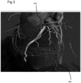
- Figure 3 shows an example produced according to an example method of the present disclosure where different rendering styles are applied to different fragments of the surface, depending on the position of the surface with respect to the layers in the depth image.
- Figure 3 shows a volume rendering of a CT dataset representing a heart, with a first structure 352 and a second structure 354 embedded in the rendering.
- the first and second structures 352, 354 are segmented mesh surfaces representing blood vessels.
- the first structure 352 is in front of the depth layer, computed from the volume data, which corresponds with the closest surface of the heart. Therefore, the first structure 352 is not occluded by the volume.
- a first rendering style in this example comprising Phong shading, is applied to the first structure 352, to convey to the viewer that the first structure 352 is in front of the heart.
- the second structure 354 lies behind the heart (behind the further layer of the depth image) and is thus occluded by the volume. Therefore, a different rendering style is applied to the second structure 354.
- the rendering style used for the second structure 354 is a silhouette style, specifically a lit silhouette. It will be appreciated that any suitable rendering style and/or effects may be applied to surfaces based on their position with respect to the layers in the depth image.
- a "toon" shading style may be applied to non-occluded surfaces while a dark silhouette may be applied to occluded surfaces. It will be appreciated that many other styles and effects are possible.
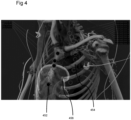
- Figure 4 shows another example of a combined rendering of a volume and a surface embedded in the volume produced according to an example method of the present disclosure.
- a first set of landmarks 452 (sternum landmarks) are in front of the volume data (representing a patient) and a second set of landmarks 454 (spine landmarks) are behind the volume data.
- Different rendering styles are used for the first and second sets of landmarks 452, 454.
- a liver surface segmentation 456 is displayed within the volume data and is occluded by the volume data. In this example, since the liver surface segmentation 456 is occluded by the volume data, it is rendered using a silhouette rendering style.
- minimally occluding effects may be used to visualize an embedded surface and the effect may vary with time in order to show the full surface over a number of rendered frames. For example, single or multiple moving contours may be rendered along the surface.
- thresholds controlling a silhouette rendering effect may be varied with time, and in yet another example, an opacity for each band of a toon shading effect may be varied with time.
- a mesh renderer may use heuristics to modify the silhouette edge during silhouette rendering to provide a consistent line thickness for various mesh sizes, resolutions and positions. For example, the area of each triangle of the mesh projected in screen-space can modify the silhouette threshold.
- a separate depth image may be obtained in the manner described above when clip planes are applied to the volume rendering. This depth image allows modifying of the surface rendering style on each side of the clip plane.
- silhouette edge rendering and toon shading are combined to produce a contrast-enhanced silhouette edge, where the three discrete toon-shaded bands closest to the silhouette edge are configured in the pattern dark-light-dark. This allows the colour of the middle band to be clearly distinguishable against both dark and light backgrounds.
- the depth image obtained during the volume rendering process may be used for other purposes than to modulate the surface rendering process.
- the depth image may be used for point picking operations, which are consistent with the rendering of the surface embedded in the volume. That is, the depth image may be used for picking the 3D position on a surface which is covered by a given pixel. This can be done directly using the surface model, e.g. using a ray-triangle intersection test or using a spatial acceleration structure.
- the depth image may be used to determine the position of the anatomical structure in the volume which is covered by the pixel.
- the depth image of the volume may be used to add additional features to the volume rendering, in order to present additional information to the viewer.
- the depth image may be used to enhance the visualization of the volume, even where no added non-volumetric surfaces are present.
- lines derived from the depth image corresponding with surfaces inherent in the volumetric dataset may be traced directly onto the image to visualize hidden structures in the volume.
- Figures 5A and 5B illustrate the application of such a method according to the present disclosure.
- Figure 5A shows a volume rendering of a volumetric dataset.
- Figure 5B shows a volume rendering of the same volumetric dataset with surfaces inherent in the volumetric dataset rendered by tracing lines to render the surfaces and combining the rendering of the surfaces with the volume rendering of the volumetric dataset.
- the outline 552 is provided from the depth image by tracing the surfaces inherent in the volume which define the boundary between valid and invalid depth values in the depth image, where invalid depth values are pixels which have no depth value assigned to them, e.g. due to no surface in the volume being encountered by the viewing ray for that pixel. This may aid the viewer in seeing the outline of an object visualized by the volume rendering.
- the depth image used for Figure 5B comprises front and back depth values for the object, and thus comprises three depth layers. Further information can be presented to the viewer by using the depth image to enhance the volume rendering.
- hidden edges 554 occluded by the object are traced on the image.
- the lines 554 representing hidden edges of the object are obtained from applying an edge-detection filter to the intermediate depth layer or to the final depth layer of the depth image.
- the lines 554 are overlaid on the rendering in order to visualize structural information on the side of the object opposite to the viewing point.
- the various lines may be traced in different colours to one another in order to convey information more effectively to the viewer.
- Figure 6 illustrates a flow chart representation of another example computer-implemented method 1000, not according to the present invention, for rendering a volumetric dataset and a surface embedded in the volumetric dataset.
- the method 1000 may be performed to render a volumetric dataset and surface embedded therein having any of the features described above with reference to the volumetric dataset 200 and surface 250 shown in Figure 2 .
- the method 1000 obtains depths of the surface, sometimes referred to herein as the geometry, and uses these depths during the volume rendering process.
- the method 1000 allows the surface to be embedded at an accurate position with respect to the volumetric dataset.
- the method 1000 comprises, at block 1002, determining depths of the surface 250 at respective locations with respect to a viewing point 10 to be used to render the volumetric dataset 200 and storing the depths in association with the respective locations.
- each of the respective locations may be associated with a pixel in the viewing plane 20.
- the depths and locations may comprise the per-pixel distance between the viewing camera and the surface embedded in the volume data.
- One or more depth values for the surface geometry may be obtained for each location.
- determining the depths of the surface 250 may comprise determining one or more depth values related to the surface 250 for each pixel in the image plane 20.
- the method 1000 comprises performing a surface rendering process for producing a surface rendering of the surface 250. Determining of the depths of the surface 250 at the respective locations may be done as part of the surface rendering process.
- the surface rendering process may, for example, comprise a rasterization-based method during which depth data is computed.
- the surface rendering process may comprise any rendering process that involves the determination of depth values relating to the surface 250. Performing the surface rendering process may result in a plurality of surface fragments being produced. That is, each surface fragment may be associated with a given pixel in the viewing plane 20. A given pixel in the viewing plane 20 may have more than one surface fragment associated with it.
- the surface rendering process comprises a depth peeling process.
- a fixed number of depth layers for the surfaces, or geometry, in the scene may be produced by rendering the surfaces in the scene a given number of times.
- determining the depths and their respective locations may comprise generating a fragment linked list as part of the surface rendering process.
- the surface rendering process comprises producing a k + -buffer, or for example, an A-buffer, or a K-buffer.
- Use of such a buffer e.g. a k + -buffer, may allow for efficient memory usage in determining and storing the depths.
- Use of such a buffer may also allow for single-pass rendering as opposed to an approach, such as depth peeling, which uses multiple passes.
- determining the depths may comprise rasterizing the surface 250 for deferred shading during volume rendering. For example, a full set of G-buffers may be determined for each depth layer for later use.
- the information stored in the G-buffers e.g. any one or more of depth information, colour information, and surface normal information relating to the surface, may be used in determining shading information when performing a volume rendering process to render the volume 200.
- the method 1000 comprises performing a volume rendering process to render the volumetric dataset 200.
- a shading process is applied during the volume rendering process and the depths of the surface 250 and the respective locations are used in the shading process.
- the volume rendering process may, for example, comprise ray casting or path tracing.
- the shading process may be applied as a step in the volume rendering process.
- performing the shading process comprises defining one or more optical properties of a point (not shown) in the volumetric dataset 200.
- the one or more optical properties of the point in the volumetric dataset 200 may be defined based on a comparison of a depth of the point in the volumetric dataset 200 with a depth of a fragment of the surface 250 stored in association with a location associated with the point.
- the point may, for example, be placed at the location in the 3D volumetric dataset where the surface fragment is located. Alternatively, the point may be located in front of or behind the surface 250, with respect to the viewing point 10.
- one or more rays 30 may be cast through the volume 200, in the manner described above with reference to Figure 2 .
- Each of these rays 30 is associated with a given pixel in the image plane 20. Further, any fragments of the surface 250 which lie along the ray 30 can be considered to be associated with points in the volumetric dataset which lie on the ray 30.
- a ray 30 corresponding to a particular pixel in the viewing plane 20 is cast from the viewing point 10 through the volume 200, points along the ray 30 are sampled to be shaded and accumulated according to the volume rendering process.
- the voxels may be classified, e.g. by use of a transfer function, to assign optical properties to each voxel. These optical properties then define how the sample point interacts with light illuminating the volume 200. Shading at the sample point can then be computed to determine optical values to be accumulated along the ray 30. The process is repeated for a plurality of sample points along the ray 30 and the optical values accumulated to obtain values for display by the pixel associated with the ray 30.
- each pixel in the viewing plane 20 also has associated therewith a depth, or more than one depth, representing a depth of the surface 250 associated with that pixel, i.e. the depth of the surface fragment lying on the path of the ray 30.
- a depth or more than one depth, representing a depth of the surface 250 associated with that pixel, i.e. the depth of the surface fragment lying on the path of the ray 30.
- the surface 250 can be embedded in the volume rendering. That is, the volume rendering can take into account the position of the surface 250 with respect to the point in the volume 200 being shaded. As mentioned above, more than one depth may be determined for each pixel in the image 20. Accordingly, the shading process may take into account the location of the point being rendered with respect to more than one surface, for example located at different depths with respect to the volume.
- Performing the shading process may comprise deriving one or more optical properties of the sample point in the volumetric dataset 200.
- the optical properties may, for example, comprise an optical opacity and colour.
- the optical properties may be derived from the acquired scalar data through classification.
- the optical properties are integrated along the ray during volume rendering..
- the optical properties may be determined by visual parameter data assigned to the sample point, for example by way of classifying the scalar value of the sample point using a transfer function. Any of the parameters described above with reference to Figure 2 may be assigned to the sample point. Further, as also described above with reference to Figure 2 , any suitable interpolation process may be used to obtain a scalar value associated with the sample point for use in the transfer function.
- the modifying of the one or more optical properties of the sample point in the volumetric dataset 200 may be based on one or more properties of the fragment or fragments of the surface 250 associated with the sample point.
- a fragment of the surface associated with the sample point may have a colour and an opacity associated therewith.
- the surface 250 may also comprise one or more shading properties which may be used during computation of shading. Some shading properties, such as local curvature and gradient magnitude, may be derived from the scalar data of the volumetric dataset 200. Other shading properties, such as a roughness of the surface, may be not derived from the scalar data.
- Shading the sample point in the volume 200 during volume rendering may comprise performing a blending process to blend a colour of the sample point with a colour of the fragment of the surface 250 which is associated with the sample point. Such values may also be used during the shading process. Accordingly, modified optical properties for the sample point may take into account the position of the sample point with respect to a surface fragment associated with the sample point and the modified optical properties may be based at least in part on properties of the surface fragment or fragments associated with the sample point.
- the ray casting process may compute the integral of the optical opacity along a viewing ray (through a given pixel) by evaluating the optical properties of the volume at sample points along the viewing ray.
- the sample points can be equally spaced.
- the sample points may be sorted front to back and alpha blending may be used to accumulate the colour and opacity along the ray.
- sample points along the viewing ray located at the depths of the surfaces along the viewing ray are sorted together with the sample points and are included in the alpha blending process.
- the shading of points during the volume rendering process may be configured to provide different rendering effects.
- the volume rendering of an object having a surface located behind it may be tinted with the colour of the surface.
- the object in the volume may be a bone and the surface may be located behind the bone and represent a landmark.
- the bone may be tinted with the colour of the landmark in one example effect.
- a silhouette effect showing the edge of a surface may be obtained by modifying points associated with the edge of the surface in a different manner to points which are not associated with the edge of a surface.
- the bone in the previous example may be tinted to show a silhouette of the landmark lying behind the bone.
- a cut-out effect may be implemented by reducing the opacity of points in the volume.
- a transparent cut-out at the location of the surface fragment may be produced by reducing the opacity of the points in the volume located at the same point as the surface fragment.
- Examples described above according to Figure 6 using volume ray casting may also be employed where a path tracing method is used to render the volume.
- the surface depth information may be only valid for the primary viewing rays i.e. and not for scattered, reflected or refracted rays.
- an embedding of the surface in the volume rendering may be obtained through modifying the optical properties of the voxels along the primary rays used during the path tracing.
- methods according to Figure 6 provide for accurate embedding of surface data in the volumetric dataset and may allow surfaces embedded in the volumetric dataset to be visualised by modifying the optical properties of points in the volumetric dataset during volume rendering in order to represent the embedded surface.
- the volume rendered typically will become invalid. That is, since the surface depth information is embedded in the shading of the volume, e.g. in a modified classification of the voxels of the volume, modifying the surface may require restarting the volume rendering process.
- the depths of the surface may be used to stop traversal of the ray when the ray reaches the surface. This may be useful when the surface is opaque, for example.
- various effects can be implemented to embed the surface in the volume.
- the surface may be visualised in a minimally occluding manner, e.g. allowing transparency effects to be implemented, while embedding the surface at an accurately determined depth with respect to the volume.
- the approach described with reference to Figure 6 may be particularly useful for rendering landmarks, such as labels of parts of an anatomy, where accurately embedding the landmark at a particular depth with respect to the volume may be desirable.
- methods described with reference to Figure 6 may be used to render any type of embedded surface and may achieve accurate placement of the visualization of the surface with respect to the volume.
- the system 601 comprises a scanner 602, the rendering apparatus 604, and a visualization unit 614.
- the system may comprise fewer components than or additional components to those illustrated in Figure 7 .
- the system 601 may comprise a computer network such as the internet.
- the scanner 602 may be any scanner for generating a dataset comprising the volumetric dataset 200, which, as described may, for example, be a medical volumetric dataset representing a portion of a patient.
- the scanner 602 may be a computed tomography (CT) scanner, a magnetic resonance imaging (MRI) scanner, a positron emission tomography (PET) scanner, an ultrasound scanner or the like.
- CT computed tomography
- MRI magnetic resonance imaging
- PET positron emission tomography
- ultrasound scanner or the like.
- the scanner 602 may, for example, be for producing a volumetric dataset representing geological data.
- the scanner 602 is connected to the rendering apparatus 604, for example via wired or wireless connection.
- the scanner 602 may be arranged to provide the volumetric dataset to the rendering apparatus 604.
- the rendering apparatus 604 comprises a processor 606 and a memory, in the form of a storage 608.
- the rendering apparatus 604 may, for example comprise a GPU.
- the rendering apparatus 604 may be arranged to perform the above described methods of volume rendering the volumetric dataset 200 and obtaining depth values from the volumetric dataset 200 and may also be arranged to perform the above described methods of rendering a combination of the volumetric dataset 200 and a surface 250 embedded in the volumetric dataset 200.
- the rendering apparatus 604 may also be arranged to perform methods described above with reference to Figure 6 wherein depth information related to the surface is obtained and is used during a volume rendering process.
- the storage 608 may comprise a machine-readable medium comprising a set of machine-readable instructions which when executed by the processor 606 cause the rendering apparatus 604 to perform one of the example methods described herein.
- the program may be stored on a computer readable medium which may be read by the rendering apparatus 604 to thereby execute the program.
- the rendering apparatus 604 may be arranged to receive directly or indirectly or otherwise acquire from the scanner 602 the volumetric dataset 200.
- the rendering apparatus 604 may further be arranged to generate or otherwise obtain the surface 250.
- the rendering apparatus 604 may comprise a processor for operating any volume rendering method capable of simulating light transport within the volumetric dataset 200. Examples of suitable rendering methods are ray casting and path tracing. In certain examples, the rendering apparatus 604 is also arranged to operate a suitable surface rendering method, such as a rasterization method, a ray-tracing method or a path-tracing method, to render the surface 250. In certain examples the rendering apparatus 604 may also be configured to perform a method of compositing the result of a volume rendering process with a result of a surface rendering process.
- the rendering apparatus 604 may be arranged to combine the volume rendering with the surface rendering by a suitable technique, for example by depth embedding or by overlaying the surface rendering on the volume rendering using a suitable compositing technique, such as alpha compositing.
- the rendering apparatus 604 may be arranged to transmit information, for example, a colour value for each pixel in an image plane, to a visualization unit 614.
- the transmission may be direct or indirect, for example via a wired connection, a wireless connection, or via the internet.
- the visualization unit 614 may comprise visualization software for displaying a two-dimensional projection of the volume 200 and surface 250 produced by the rendering apparatus 604.
- the visualization unit 614 may comprise a display screen, and one or more graphics hardware or software components.
- the visualization unit 614 may be or comprise a mobile device.
- the visualization unit 614 may comprise a virtual-reality device.
- one of the methods described herein may be selected.
- Each method has different advantages and these advantages may be taken into account when deciding which method to use for a given rendering task.
- the method described with reference to Figure 1 wherein depths obtained from a volume rendering process are used in a surface rendering process, provides the advantage, among others, that the surface can be changed without requiring restarting of the volume rendering process while also allowing for different rendering effects, such as non-obtrusive rendering effects, to be applied. This may make it particularly suitable, for example, for live editing of landmarks and/or annotations embedded in the volume.
- the method described with reference to Figure 6 provides the advantage, among others, of accurate embedding of the surface at a position with respect to the volumetric dataset while, similarly, also allowing for different rendering effects, such as non-obtrusive rendering effects, to be applied.
- the volume rendering and the surface rendering produced according to methods described herein may be considered to be fully decoupled from another, i.e. lighting effects or the like used to render to the volume are not visible in the surface rendering, and vice versa.
- some shading effects may be shared between the volume rendering and the surface rendering. For example, shadows and ambient occlusion effects may be shared.
- deferred shading may be used for the surface rendering.
- Example methods described herein may be used in non-medical imaging environments. Any applications using 3D rendering of hybrid volume and surface data, such as computational fluid dynamics, computer assisted design, or manufacturing, may benefit from the ability to handle complex and accurate interactions between a surface and volume in physically based rendering.
Landscapes
- Engineering & Computer Science (AREA)
- Physics & Mathematics (AREA)
- General Physics & Mathematics (AREA)
- Theoretical Computer Science (AREA)
- Computer Graphics (AREA)
- Computer Vision & Pattern Recognition (AREA)
- Geometry (AREA)
- Image Generation (AREA)
Claims (11)
- Computerimplementiertes Verfahren für ein Rendering eines volumetrischen Datensatzes (200) und einer Oberfläche (250), die in den volumetrischen Datensatz (200) eingebettet ist, das Verfahren umfassend:Durchführen eines Volumenrenderingprozesses, um ein Volumenrendering eines volumetrischen Datensatzes (200) zu erzeugen;Bestimmen, basierend auf dem Volumenrenderingprozess, von Tiefen von jeweiligen Positionen in dem Volumenrendering und Speichern der Tiefen in Zusammenhang mit den jeweiligen Positionen;Durchführen eines Oberflächenrenderingprozesses, um ein Oberflächenrendering einer Oberfläche (250) zu erzeugen, der Oberflächenrenderingprozess umfassend ein Verwenden der Tiefen und jeweiligen Positionen; undKombinieren des Volumenrenderings und des Oberflächenrenderings zu einem kombinierten Rendering des volumetrischen Datensatzes (200) und der Oberfläche (250);dadurch gekennzeichnet, dass:
das Bestimmen der Tiefen der jeweiligen Positionen in dem Volumenrendering umfasst:
Verwenden eines Raycasting-Prozesses, um Anfangswerte für die Tiefen zu erhalten, durch:Werfen einer Vielzahl von Strahlen (30) durch den volumetrischen Datensatz hindurch, wobei jeder Strahl mit einer Position der jeweiligen Positionen zusammenhängt;Bestimmen, entlang jedes der Strahlen (30), mindestens eines Tiefenwerts, der mit einer zuvor bestimmen Änderung eines Werts in Bezug auf den volumetrischen Datensatz (200) zusammenhängt, und Speichern des mindestens einen Tiefenwerts in einer Datenstruktur; undAuswählen, gemäß zuvor bestimmten Kriterien, einer zuvor bestimmten Anzahl des mindestens einen Tiefenwerts an jeder jeweiliger Position, um als Anfangswerte für die Tiefen an jeder der jeweiligen Positionen verwendet zu werden; undModifizieren der Anfangswerte für die Tiefen während des Volumenrenderingprozesses unter Verwendung von Daten von Streupositionen, die aus einem physikalisch basierten Renderingprozess erhalten werden. - Verfahren nach Anspruch 1:
wobei der Oberflächenrenderingprozess, basierend auf einem Vergleich einer Tiefe eines Fragments der Oberfläche (250) mit einer Tiefe, die in Zusammenhang mit einer Position, die mit dem Fragment der Oberfläche (250) zusammenhängt, gespeichert ist, ein Clipping des Fragments der Oberfläche (250) von dem Oberflächenrendering umfasst. - Verfahren nach Anspruch 1 oder 2:
wobei der Oberflächenrenderingprozess, basierend auf einem Vergleich einer Tiefe eines Fragments der Oberfläche (250) mit einer Tiefe, die in Zusammenhang mit einer Position, die mit dem Fragment der Oberfläche (250) zusammenhängt, gespeichert ist, ein Auswählen eines Renderingstils oder -parameters zur Verwendung bei dem Rendering des Fragments durch den Oberflächenrenderingprozess umfasst. - Verfahren nach einem der Ansprüche 1 bis 3:
wobei der Volumenrenderingprozess einen physikalisch basierten Renderingprozess umfasst und die Tiefen durch Abtasten von Pfaden, die während des physikalisch basierten Renderingprozesses verfolgt werden, erhalten werden. - Verfahren nach Anspruch 4, wobei die Tiefen durch Bestimmen, für jedes Pixel in dem Volumenrendering, eines durchschnittlichen Tiefenwerts aus einer Vielzahl von Pfaden erhalten werden, die abgetastet werden, um das Pixel durch den physikalisch basierten Renderingprozess zu rendern.
- Verfahren nach einem der vorstehenden Ansprüche, wobei das Bestimmen der Tiefen das Bestimmen, für mindestens einige der jeweiligen Positionen in dem Volumenrendering, einer Vielzahl von Tiefen pro Position und ein Speichern jeder der Vielzahl von Tiefen in Zusammenhang mit einer Position der Positionen umfasst.
- Verfahren nach Anspruch 3, umfassend:
Auswählen, für das Fragment, des Oberflächenrenderingstils oder -parameters zur Verwendung in dem Oberflächenrenderingprozess, der verwendet wird, um das Fragment basierend darauf zu rendern, ob der Vergleich der Tiefe des Fragments mit der Tiefe an der Position in dem Volumenrendering, die mit dem Fragment zusammenhängt, angibt, dass das Fragment durch ein Objekt in dem volumetrischen Datensatz (200) verdeckt wird oder nicht verdeckt wird. - Verfahren nach Anspruch 6, umfassend:
Auswählen, für ein gegebenes Fragment der Oberfläche (250), eines Oberflächenrenderingstils oder -parameters zur Verwendung in dem Oberflächenrenderingprozess, der verwendet wird, um das Fragment zu rendern, basierend darauf, ob ein Vergleich einer Tiefe, die mit dem Fragment zusammenhängt, mit einer Tiefe der Tiefen an einer Position, die mit dem Fragment zusammenhängt, angibt, dass sich das Fragment vor, innerhalb oder hinter einem Objekt in dem volumetrischen Datensatz (200) befindet. - Satz von maschinenlesbaren Anweisungen, die, wenn sie durch einen Prozessor (606) ausgeführt werden, veranlassen, dass ein Verfahren nach einem der Ansprüche 1 bis 8 durchgeführt wird.
- Maschinenlesbares Medium, umfassend einen Satz von maschinenlesbaren Anweisungen nach Anspruch 9.
- Einrichtung (604) umfassend einen Prozessor (606) und einen Speicher (608), umfassend einen Satz von maschinenlesbaren Anweisungen, die, wenn sie durch den Prozessor (606) ausgeführt werden, den Prozessor (606) veranlassen, ein Verfahren nach einem der Ansprüche 1 bis 8 durchzuführen.
Priority Applications (3)
| Application Number | Priority Date | Filing Date | Title |
|---|---|---|---|
| EP20161937.6A EP3879498B1 (de) | 2020-03-09 | 2020-03-09 | Verfahren zum rendern eines volumens und einer in dem volumen eingebetteten oberfläche |
| US17/154,568 US11810243B2 (en) | 2020-03-09 | 2021-01-21 | Method of rendering a volume and a surface embedded in the volume |
| CN202110253727.0A CN113436303B (zh) | 2020-03-09 | 2021-03-09 | 渲染体积和嵌入体积中的表面的方法 |
Applications Claiming Priority (1)
| Application Number | Priority Date | Filing Date | Title |
|---|---|---|---|
| EP20161937.6A EP3879498B1 (de) | 2020-03-09 | 2020-03-09 | Verfahren zum rendern eines volumens und einer in dem volumen eingebetteten oberfläche |
Publications (3)
| Publication Number | Publication Date |
|---|---|
| EP3879498A1 EP3879498A1 (de) | 2021-09-15 |
| EP3879498C0 EP3879498C0 (de) | 2025-05-21 |
| EP3879498B1 true EP3879498B1 (de) | 2025-05-21 |
Family
ID=69784238
Family Applications (1)
| Application Number | Title | Priority Date | Filing Date |
|---|---|---|---|
| EP20161937.6A Active EP3879498B1 (de) | 2020-03-09 | 2020-03-09 | Verfahren zum rendern eines volumens und einer in dem volumen eingebetteten oberfläche |
Country Status (3)
| Country | Link |
|---|---|
| US (1) | US11810243B2 (de) |
| EP (1) | EP3879498B1 (de) |
| CN (1) | CN113436303B (de) |
Families Citing this family (10)
| Publication number | Priority date | Publication date | Assignee | Title |
|---|---|---|---|---|
| US11398072B1 (en) * | 2019-12-16 | 2022-07-26 | Siemens Healthcare Gmbh | Method of obtaining a set of values for a respective set of parameters for use in a physically based path tracing process and a method of rendering using a physically based path tracing process |
| US11676052B2 (en) * | 2020-04-15 | 2023-06-13 | Micron Technology, Inc. | Apparatuses and methods for inference processing on edge devices |
| EP3996050A1 (de) * | 2020-11-05 | 2022-05-11 | Koninklijke Philips N.V. | Bildwiedergabeverfahren für tomographische bilddaten |
| CN114694805A (zh) * | 2020-12-30 | 2022-07-01 | 上海联影医疗科技股份有限公司 | 医学图像渲染方法、装置、设备和介质 |
| EP4033451A1 (de) | 2021-01-20 | 2022-07-27 | Siemens Healthcare GmbH | Interaktive bildbearbeitung mit hilfe vorzeichenbehafteter abstandsfelder |
| US11688125B2 (en) * | 2021-03-09 | 2023-06-27 | Canon Medical Systems Corporation | Image processing apparatus and method to perform a ray casting algorithm to generate a rendered image from a volumetric data set |
| US12236517B2 (en) * | 2021-11-16 | 2025-02-25 | Disney Enterprises, Inc. | Techniques for multi-view neural object modeling |
| US12254570B2 (en) * | 2022-05-03 | 2025-03-18 | Adobe Inc. | Generating three-dimensional representations for digital objects utilizing mesh-based thin volumes |
| EP4322111A1 (de) * | 2022-08-12 | 2024-02-14 | Siemens Healthineers AG | Volumetrisches schälverfahren für monte-carlo-pfadverfolgung |
| EP4407562A1 (de) | 2023-01-30 | 2024-07-31 | Siemens Healthineers AG | Verfahren zur dynamischen anpassung eines belichtungswertes bei interaktiver wiedergabe |
Family Cites Families (8)
| Publication number | Priority date | Publication date | Assignee | Title |
|---|---|---|---|---|
| US8355021B2 (en) * | 2007-05-17 | 2013-01-15 | Siemens Aktiengesellschaft | Fused volume rendering |
| US20130328874A1 (en) | 2012-06-06 | 2013-12-12 | Siemens Medical Solutions Usa, Inc. | Clip Surface for Volume Rendering in Three-Dimensional Medical Imaging |
| US10565774B2 (en) | 2015-09-03 | 2020-02-18 | Siemens Healthcare Gmbh | Visualization of surface-volume hybrid models in medical imaging |
| US10893262B2 (en) * | 2017-02-07 | 2021-01-12 | Siemens Healthcare Gmbh | Lightfield rendering based on depths from physically-based volume rendering |
| US10311631B2 (en) | 2017-05-12 | 2019-06-04 | Siemens Healthcare Gmbh | Light path fusion for rendering surface and volume data in medical imaging |
| EP3462418B1 (de) * | 2017-09-28 | 2024-06-19 | Siemens Healthineers AG | Verfahren und vorrichtung zur darstellung von materialeigenschaften |
| US10665007B2 (en) | 2018-01-15 | 2020-05-26 | Siemens Healthcare Gmbh | Hybrid interactive mode for rendering medical images with ray tracing |
| US11399806B2 (en) * | 2019-10-22 | 2022-08-02 | GE Precision Healthcare LLC | Method and system for providing freehand render start line drawing tools and automatic render preset selections |
-
2020
- 2020-03-09 EP EP20161937.6A patent/EP3879498B1/de active Active
-
2021
- 2021-01-21 US US17/154,568 patent/US11810243B2/en active Active
- 2021-03-09 CN CN202110253727.0A patent/CN113436303B/zh active Active
Non-Patent Citations (1)
| Title |
|---|
| CHRISTIAN TIETJEN ET AL: "Combining Silhouettes, Surface, and Volume Rendering for Surgery Education and Planning", 1 January 2005 (2005-01-01), XP055723146, Retrieved from the Internet <URL:https://diglib.eg.org/bitstream/handle/10.2312/VisSym.EuroVis05.303-310/303-310.pdf?sequence=1&isAllowed=y> DOI: 10.2312/vissym/eurovis05/303-310 * |
Also Published As
| Publication number | Publication date |
|---|---|
| US20210279942A1 (en) | 2021-09-09 |
| EP3879498C0 (de) | 2025-05-21 |
| CN113436303B (zh) | 2024-11-05 |
| EP3879498A1 (de) | 2021-09-15 |
| CN113436303A (zh) | 2021-09-24 |
| US11810243B2 (en) | 2023-11-07 |
Similar Documents
| Publication | Publication Date | Title |
|---|---|---|
| EP3879498B1 (de) | Verfahren zum rendern eines volumens und einer in dem volumen eingebetteten oberfläche | |
| CN109584349B (zh) | 用于渲染材料属性的方法和设备 | |
| US8150111B2 (en) | Methods, systems, and computer program products for processing three-dimensional image data to render an image from a viewpoint within or beyond an occluding region of the image data | |
| Viola et al. | Importance-driven feature enhancement in volume visualization | |
| Stytz et al. | Three-dimensional medical imaging: algorithms and computer systems | |
| CN109801254B (zh) | 医学成像中的传递函数确定 | |
| US10311631B2 (en) | Light path fusion for rendering surface and volume data in medical imaging | |
| CN104488002A (zh) | 行李可视化和虚拟开检 | |
| Haubner et al. | Virtual reality in medicine-computer graphics and interaction techniques | |
| US12450827B2 (en) | Technique for dynamically adapting an exposure value in interactive rendering | |
| EP3989172A1 (de) | Verfahren zur erzeugung einer computerbasierten visualisierung von medizinischen 3d-bilddaten | |
| US12002147B2 (en) | Method and system for optimizing distance estimation | |
| CN108986196A (zh) | 用于外科决策支持的关联的照片级真实的3d可视化 | |
| Turlington et al. | New techniques for efficient sliding thin-slab volume visualization | |
| Viola | Importance-driven expressive visualization | |
| JP2022138098A (ja) | 医用画像処理装置および方法 | |
| EP4645218A1 (de) | Computerimplementiertes verfahren zur darstellung eines volumetrischen datensatzes zur darstellung eines medizinischen volumens | |
| EP4322111A1 (de) | Volumetrisches schälverfahren für monte-carlo-pfadverfolgung | |
| EP3767593A1 (de) | Verfahren zur erzeugung einer computerbasierten darstellung einer oberfläche, die ein volumen durchschneidet, und verfahren zum rendering einer visualisierung einer oberfläche, die ein volumen durchschneidet | |
| JPH0793926B2 (ja) | ディスプレイリスト表面データを使用する手術シミュレーション装置 | |
| JP2024028133A (ja) | 医療ボリュームデータをレンダリングするためのコンピュータ実施方法 | |
| Correa | Illustrative Deformation of volumetric objects and other graphical models | |
| Russ et al. | Real-time surface analysis and tagged material cleansing for virtual colonoscopy. | |
| Faynshteyn | Context-Preserving Volume Image Exploration Using A 3D Painting Metaphor | |
| Behroozi | Volumetric Visualization of MRI data |
Legal Events
| Date | Code | Title | Description |
|---|---|---|---|
| PUAI | Public reference made under article 153(3) epc to a published international application that has entered the european phase |
Free format text: ORIGINAL CODE: 0009012 |
|
| STAA | Information on the status of an ep patent application or granted ep patent |
Free format text: STATUS: REQUEST FOR EXAMINATION WAS MADE |
|
| 17P | Request for examination filed |
Effective date: 20200309 |
|
| AK | Designated contracting states |
Kind code of ref document: A1 Designated state(s): AL AT BE BG CH CY CZ DE DK EE ES FI FR GB GR HR HU IE IS IT LI LT LU LV MC MK MT NL NO PL PT RO RS SE SI SK SM TR |
|
| RBV | Designated contracting states (corrected) |
Designated state(s): AL AT BE BG CH CY CZ DE DK EE ES FI FR GB GR HR HU IE IS IT LI LT LU LV MC MK MT NL NO PL PT RO RS SE SI SK SM TR |
|
| RAP1 | Party data changed (applicant data changed or rights of an application transferred) |
Owner name: SIEMENS HEALTHINEERS AG |
|
| STAA | Information on the status of an ep patent application or granted ep patent |
Free format text: STATUS: EXAMINATION IS IN PROGRESS |
|
| 17Q | First examination report despatched |
Effective date: 20240614 |
|
| 17Q | First examination report despatched |
Effective date: 20240627 |
|
| GRAP | Despatch of communication of intention to grant a patent |
Free format text: ORIGINAL CODE: EPIDOSNIGR1 |
|
| STAA | Information on the status of an ep patent application or granted ep patent |
Free format text: STATUS: GRANT OF PATENT IS INTENDED |
|
| INTG | Intention to grant announced |
Effective date: 20241219 |
|
| GRAS | Grant fee paid |
Free format text: ORIGINAL CODE: EPIDOSNIGR3 |
|
| GRAA | (expected) grant |
Free format text: ORIGINAL CODE: 0009210 |
|
| STAA | Information on the status of an ep patent application or granted ep patent |
Free format text: STATUS: THE PATENT HAS BEEN GRANTED |
|
| AK | Designated contracting states |
Kind code of ref document: B1 Designated state(s): AL AT BE BG CH CY CZ DE DK EE ES FI FR GB GR HR HU IE IS IT LI LT LU LV MC MK MT NL NO PL PT RO RS SE SI SK SM TR |
|
| REG | Reference to a national code |
Ref country code: GB Ref legal event code: FG4D |
|
| REG | Reference to a national code |
Ref country code: CH Ref legal event code: EP |
|
| REG | Reference to a national code |
Ref country code: DE Ref legal event code: R096 Ref document number: 602020051499 Country of ref document: DE |
|
| REG | Reference to a national code |
Ref country code: IE Ref legal event code: FG4D |
|
| U01 | Request for unitary effect filed |
Effective date: 20250604 |
|
| U07 | Unitary effect registered |
Designated state(s): AT BE BG DE DK EE FI FR IT LT LU LV MT NL PT RO SE SI Effective date: 20250612 |
|
| PG25 | Lapsed in a contracting state [announced via postgrant information from national office to epo] |
Ref country code: ES Free format text: LAPSE BECAUSE OF FAILURE TO SUBMIT A TRANSLATION OF THE DESCRIPTION OR TO PAY THE FEE WITHIN THE PRESCRIBED TIME-LIMIT Effective date: 20250521 |
|
| PG25 | Lapsed in a contracting state [announced via postgrant information from national office to epo] |
Ref country code: GR Free format text: LAPSE BECAUSE OF FAILURE TO SUBMIT A TRANSLATION OF THE DESCRIPTION OR TO PAY THE FEE WITHIN THE PRESCRIBED TIME-LIMIT Effective date: 20250822 Ref country code: NO Free format text: LAPSE BECAUSE OF FAILURE TO SUBMIT A TRANSLATION OF THE DESCRIPTION OR TO PAY THE FEE WITHIN THE PRESCRIBED TIME-LIMIT Effective date: 20250821 |
|
| PG25 | Lapsed in a contracting state [announced via postgrant information from national office to epo] |
Ref country code: PL Free format text: LAPSE BECAUSE OF FAILURE TO SUBMIT A TRANSLATION OF THE DESCRIPTION OR TO PAY THE FEE WITHIN THE PRESCRIBED TIME-LIMIT Effective date: 20250521 |
|
| PG25 | Lapsed in a contracting state [announced via postgrant information from national office to epo] |
Ref country code: HR Free format text: LAPSE BECAUSE OF FAILURE TO SUBMIT A TRANSLATION OF THE DESCRIPTION OR TO PAY THE FEE WITHIN THE PRESCRIBED TIME-LIMIT Effective date: 20250521 |
|
| PG25 | Lapsed in a contracting state [announced via postgrant information from national office to epo] |
Ref country code: RS Free format text: LAPSE BECAUSE OF FAILURE TO SUBMIT A TRANSLATION OF THE DESCRIPTION OR TO PAY THE FEE WITHIN THE PRESCRIBED TIME-LIMIT Effective date: 20250821 |
|
| PG25 | Lapsed in a contracting state [announced via postgrant information from national office to epo] |
Ref country code: IS Free format text: LAPSE BECAUSE OF FAILURE TO SUBMIT A TRANSLATION OF THE DESCRIPTION OR TO PAY THE FEE WITHIN THE PRESCRIBED TIME-LIMIT Effective date: 20250921 |