EP3879256A1 - Cholesterol measurement device - Google Patents
Cholesterol measurement device Download PDFInfo
- Publication number
- EP3879256A1 EP3879256A1 EP19882842.8A EP19882842A EP3879256A1 EP 3879256 A1 EP3879256 A1 EP 3879256A1 EP 19882842 A EP19882842 A EP 19882842A EP 3879256 A1 EP3879256 A1 EP 3879256A1
- Authority
- EP
- European Patent Office
- Prior art keywords
- strip
- unit
- light
- measurement
- intensity
- Prior art date
- Legal status (The legal status is an assumption and is not a legal conclusion. Google has not performed a legal analysis and makes no representation as to the accuracy of the status listed.)
- Pending
Links
Images


Classifications
-
- G—PHYSICS
- G01—MEASURING; TESTING
- G01N—INVESTIGATING OR ANALYSING MATERIALS BY DETERMINING THEIR CHEMICAL OR PHYSICAL PROPERTIES
- G01N21/00—Investigating or analysing materials by the use of optical means, i.e. using sub-millimetre waves, infrared, visible or ultraviolet light
- G01N21/84—Systems specially adapted for particular applications
- G01N21/8483—Investigating reagent band
-
- G—PHYSICS
- G01—MEASURING; TESTING
- G01N—INVESTIGATING OR ANALYSING MATERIALS BY DETERMINING THEIR CHEMICAL OR PHYSICAL PROPERTIES
- G01N33/00—Investigating or analysing materials by specific methods not covered by groups G01N1/00 - G01N31/00
- G01N33/48—Biological material, e.g. blood, urine; Haemocytometers
- G01N33/50—Chemical analysis of biological material, e.g. blood, urine; Testing involving biospecific ligand binding methods; Immunological testing
- G01N33/52—Use of compounds or compositions for colorimetric, spectrophotometric or fluorometric investigation, e.g. use of reagent paper and including single- and multilayer analytical elements
- G01N33/525—Multi-layer analytical elements
- G01N33/526—Multi-layer analytical elements the element being adapted for a specific analyte
-
- G—PHYSICS
- G01—MEASURING; TESTING
- G01N—INVESTIGATING OR ANALYSING MATERIALS BY DETERMINING THEIR CHEMICAL OR PHYSICAL PROPERTIES
- G01N21/00—Investigating or analysing materials by the use of optical means, i.e. using sub-millimetre waves, infrared, visible or ultraviolet light
- G01N21/17—Systems in which incident light is modified in accordance with the properties of the material investigated
- G01N21/25—Colour; Spectral properties, i.e. comparison of effect of material on the light at two or more different wavelengths or wavelength bands
-
- G—PHYSICS
- G01—MEASURING; TESTING
- G01N—INVESTIGATING OR ANALYSING MATERIALS BY DETERMINING THEIR CHEMICAL OR PHYSICAL PROPERTIES
- G01N21/00—Investigating or analysing materials by the use of optical means, i.e. using sub-millimetre waves, infrared, visible or ultraviolet light
- G01N21/17—Systems in which incident light is modified in accordance with the properties of the material investigated
- G01N21/47—Scattering, i.e. diffuse reflection
-
- G—PHYSICS
- G01—MEASURING; TESTING
- G01N—INVESTIGATING OR ANALYSING MATERIALS BY DETERMINING THEIR CHEMICAL OR PHYSICAL PROPERTIES
- G01N21/00—Investigating or analysing materials by the use of optical means, i.e. using sub-millimetre waves, infrared, visible or ultraviolet light
- G01N21/75—Systems in which material is subjected to a chemical reaction, the progress or the result of the reaction being investigated
- G01N21/77—Systems in which material is subjected to a chemical reaction, the progress or the result of the reaction being investigated by observing the effect on a chemical indicator
- G01N21/78—Systems in which material is subjected to a chemical reaction, the progress or the result of the reaction being investigated by observing the effect on a chemical indicator producing a change of colour
-
- G—PHYSICS
- G01—MEASURING; TESTING
- G01N—INVESTIGATING OR ANALYSING MATERIALS BY DETERMINING THEIR CHEMICAL OR PHYSICAL PROPERTIES
- G01N33/00—Investigating or analysing materials by specific methods not covered by groups G01N1/00 - G01N31/00
- G01N33/48—Biological material, e.g. blood, urine; Haemocytometers
- G01N33/50—Chemical analysis of biological material, e.g. blood, urine; Testing involving biospecific ligand binding methods; Immunological testing
- G01N33/52—Use of compounds or compositions for colorimetric, spectrophotometric or fluorometric investigation, e.g. use of reagent paper and including single- and multilayer analytical elements
-
- G—PHYSICS
- G01—MEASURING; TESTING
- G01N—INVESTIGATING OR ANALYSING MATERIALS BY DETERMINING THEIR CHEMICAL OR PHYSICAL PROPERTIES
- G01N33/00—Investigating or analysing materials by specific methods not covered by groups G01N1/00 - G01N31/00
- G01N33/48—Biological material, e.g. blood, urine; Haemocytometers
- G01N33/50—Chemical analysis of biological material, e.g. blood, urine; Testing involving biospecific ligand binding methods; Immunological testing
- G01N33/92—Chemical analysis of biological material, e.g. blood, urine; Testing involving biospecific ligand binding methods; Immunological testing involving lipids, e.g. cholesterol, lipoproteins, or their receptors
-
- G—PHYSICS
- G01—MEASURING; TESTING
- G01N—INVESTIGATING OR ANALYSING MATERIALS BY DETERMINING THEIR CHEMICAL OR PHYSICAL PROPERTIES
- G01N21/00—Investigating or analysing materials by the use of optical means, i.e. using sub-millimetre waves, infrared, visible or ultraviolet light
- G01N21/75—Systems in which material is subjected to a chemical reaction, the progress or the result of the reaction being investigated
- G01N21/77—Systems in which material is subjected to a chemical reaction, the progress or the result of the reaction being investigated by observing the effect on a chemical indicator
- G01N2021/7756—Sensor type
- G01N2021/7759—Dipstick; Test strip
-
- G—PHYSICS
- G01—MEASURING; TESTING
- G01N—INVESTIGATING OR ANALYSING MATERIALS BY DETERMINING THEIR CHEMICAL OR PHYSICAL PROPERTIES
- G01N21/00—Investigating or analysing materials by the use of optical means, i.e. using sub-millimetre waves, infrared, visible or ultraviolet light
- G01N21/75—Systems in which material is subjected to a chemical reaction, the progress or the result of the reaction being investigated
- G01N21/77—Systems in which material is subjected to a chemical reaction, the progress or the result of the reaction being investigated by observing the effect on a chemical indicator
- G01N2021/7769—Measurement method of reaction-produced change in sensor
- G01N2021/7773—Reflection
Definitions
- the present invention relates to a cholesterol measurement device, and more particularly, to a cholesterol measurement device using a color development method that changes the color development of a measurement strip.
- the quantity of total cholesterol in serum, plasma, or blood is known as one of indicators of indicating the risk of coronary arteriosclerosis.
- the concentration of blood cholesterol As a result, through analysis of the concentration of blood cholesterol, the occurrence and possibility of diseases such as arteriosclerosis have been diagnosed and prevented.
- Methods of measuring cholesterol include an electrochemical method which measures a change in electrical resistance value according to the quantity of a cholesterol component, a color development method which measures the degree of change by changing the color development of a strip, and the like.
- a measuring instrument body emits light of LED with a specific wavelength band on a color developed portion according to a color developed from the measurement strip and then a photo diode (PD) detects the intensity of reflected light. At this time, the intensity of reflected light is changed according to the degree of color development of a reflective surface of a check strip and the intensity of emitted light.
- PD photo diode
- the cholesterol measurement device using the color development method emits light with an LED on the measurement strip, and the photo diode (PD) detects the intensity of light reflected by the measurement strip to measure the quantity of cholesterol in a specimen.
- the photo diode (PD) detects the intensity of light reflected by the measurement strip to measure the quantity of cholesterol in a specimen.
- the cholesterol measurement device using the color development method initially sets the emitted intensity of LED light through calibration to be constant, but the deterioration of the LED component occurs according to the quantity of use over time, and as a result, a phenomenon of decreasing the intensity of light emitted from the LED may occur.
- the LED of the measuring instrument should always emit a constant intensity of light, or check whether the constant intensity of light is emitted.
- each measuring instrument manufacturer provides a check strip with a specific gray value, and should perform an operation of generating an error message or re-controlling the intensity of emitted light of the LED by determining that the intensity of light emitted from the LED has been changed out of a measurement value of a desired section when a reflection value of the strip is measured by the check strip.
- a specimen of blood or serum is dropped into a specimen inlet of the measurement strip, but at this time, when the specimen is dropped out of the specimen inlet or a dose or more of specimen is dropped in the specimen inlet due to a user's mistake, the specimen overflows into a measurement window of the measuring instrument body, not the measurement strip.
- the measurement unit of the cholesterol measuring instrument When the specimen overflows into the measurement window, the measurement unit of the cholesterol measuring instrument is contaminated, and as a result, contaminants need to be quickly removed from the measuring instrument, but the specimen is inserted between the measurement strip and a strip fixation device into which the measurement strip is inserted, and thus, there was a problem in that it is not easy to clean the measuring instrument.
- the specimen is solidified in the strip fixation device, and as a result, in some cases, the measurement strip is not inserted.
- the cholesterol measurement device in order to record the values measured by the cholesterol measurement device, there are methods of transcribing and printing the values displayed on an LCD, etc.
- the transcribing method since there is a possibility of writing an incorrect value due to a typing error, the measured value is printed using a printer to be confirmed.
- An object of the present invention is to provide a cholesterol measurement device capable of having no fear of loss and solving an inconvenience to store a check strip separately by changing a check strip of confirming whether the intensity of light is abnormal into a block shape to be provided integrally with a measuring instrument body.
- Another object of the present invention is to provide a cholesterol measurement device capable of solving problems caused by a deviation of a check strip when a light-intensity check member of confirming whether the light intensity is abnormal is integrally provided to inspect whether the light intensity is abnormal.
- Yet another object of the present invention is to provide a cholesterol measurement device capable of ensuring the accuracy of cholesterol measurement by automatically confirming everyday whether the light intensity is abnormal.
- Another object of the present invention is to provide a cholesterol measurement device capable of cleaning a measurement unit by separating a strip fixation unit into which a measurement strip is inserted to clean the measurement unit.
- Another object of the present invention is to provide a cholesterol measurement device capable of cleaning a measurement unit by easily cleaning the measurement unit to ensure reliability when measuring cholesterol and improve the measurement accuracy.
- Yet another object of the present invention is to provide a cholesterol measurement device including a printer which is detachable from a measuring instrument body and portable.
- an embodiment of the present invention provides a cholesterol measurement device including: a measuring instrument body which includes a measurement unit where a measurement strip is positioned and a light-emitting unit emitting light to the measurement unit and detects the intensity of light reflecting after emitting the light to the measurement strip to measure the quantity of cholesterol; and a light-intensity check member which is mounted and integrally provided on the measuring instrument body and reflects the light emitted from the light-emitting unit to check whether the intensity of light is abnormal.
- the light-intensity check member may have a block shape having a flat lower surface.
- the cholesterol measurement device may further include a spring member elastically supporting the light-intensity check member.
- a measurement window member through which the light emitted from the light-emitting unit passes may be positioned in the measurement unit, and the light-intensity check member may be elastically supported by the spring member to be positioned in close contact with the measurement window member.
- the measuring instrument body may include a body housing member of which the measurement unit where the measurement strip is positioned is provided at one side and the light-emitting unit emitting the light to the measurement unit is provided therein; and an opening/closing member opening and closing the measurement unit, and the light-intensity check member may be positioned on a lower surface of the opening/closing member.
- a measurement window member through which the light emitted from the light-emitting unit passes may be positioned in the measurement unit, and the light-intensity check member may be elastically supported by a spring member in the state where the opening/closing member is closed, and be positioned in close contact with the measurement window member.
- a strip inlet may be positioned at one side of the opening/closing member so that the measurement strip can be inserted between the light-intensity check member and the measurement window member in the state where the opening/closing member is closed, and the light-intensity check member may have an inclined surface which is positioned at a front end side positioned toward the strip inlet to guide the insertion of the measurement strip.
- the measuring instrument body may include a real time clock (RTC), and include a light-intensity abnormality checking unit which checks whether a date has changed when power is turned ON, operates the light-emitting unit when the date is changed to emit the light to the light-intensity check member, and checks whether the light-emitting unit is abnormal by the light reflected by the light-intensity check member.
- RTC real time clock
- An embodiment of the present invention may provide the cholesterol measurement device capable of cleaning the measurement unit by including a strip fixation unit to which the measurement strip is inserted and detachably coupled, which is detachable from the measuring instrument body, and a coupling unit for the strip fixation unit which is mounted and positioned on the measuring instrument body and is detachably coupled with the strip fixation unit.
- the strip fixation unit may include strip side support members which are spaced apart from each other so that the measurement strip is inserted therebetween and support both sides of the measurement strip; and a strip front-end support member which has both end sides which are connected to one end side of the pair of spaced strip side support members and supports a front-end of the measurement strip, wherein a first slide coupling groove may be positioned in a longitudinal direction at any one side of an outer side of the measurement strip and an inner side of the strip side support member, and a first slide rail unit inserted into the first slide coupling groove may be positioned to protrude at the other side of the outer side of the measurement strip and the inner side of the strip side support member.
- the coupling unit for the strip fixation unit may include side support members for strip fixation unit spaced apart from each other to support the outer sides of the strip side support members of the strip fixation unit; and a front support member for strip fixation unit supporting the outer side of the strip front-end support member, a second slide coupling groove may be positioned at any one side of an inner side of the side support member for strip fixation unit and an outer side of the strip side support member, and a second slide rail unit may be positioned at the other side of the inner side of the side support member for strip fixation unit and the outer side of the strip side support member to be inserted into the second slide coupling groove and slided.
- the outer side of the strip side support member of the strip fixation unit and the inner side of the side support member for strip fixation unit of the coupling unit for the strip fixation unit may have a spacing of at least 0.01 mm to 2.0 mm.
- the spacing may be filled by the outer side of the strip side support member while the strip side support member is elastically modified when the measurement strip is inserted into the strip fixation unit.
- a width of the measurement strip may be formed to be larger by 0.02 mm to 4.0 mm than the spacing between the inner sides of the strip side support members corresponding thereto.
- a coupling guide groove may be positioned at any one side of the inner side of the front support member for strip fixation unit and the outer side of the strip front-end support member, and a coupling guide rail unit inserted into the coupling guide groove may be positioned to protrude at the other side of the inner side of the front support member for strip fixation unit and the outer side of the strip front-end support member.
- the measurement unit may further include a fixation locking unit capable of locking the position of the strip fixation unit coupled to the coupling unit for the strip fixation unit.
- the fixation locking unit may include a first locking unit positioned at the rear end side of the strip fixation unit; and a second locking unit positioned at the rear end side of the coupling unit for the strip fixation unit and positioned to be locked with the first locking unit.
- the second locking unit includes a locking groove formed on the lower surface of the coupling unit for the strip fixation unit
- the first locking unit may include a wedge-shaped locking step which is inserted to the locking groove at an end side thereof, and an elastic support member that elastically supports and presses the locking step to separate the locking step from the locking groove.
- a pressing groove indicating a pressing position of the elastic support member may be positioned on the upper surface of the elastic support member, and the elastic support member may descend when a portion where the pressing groove is positioned is pressed so that the locking step may be separated from the locking groove.
- the cholesterol measurement device may further include a printer body which is detachably coupled with the measuring instrument body and electrically connected with the measuring instrument body to print a result of cholesterol measurement values measured by the measuring instrument body and is embedded with a rechargeable battery.
- the locking member for locking and fixing the measuring instrument body is positioned to protrude on the measuring instrument seating unit of the printer body and the locking member may have a ⁇ -shaped shape and protrude on the measuring instrument seating unit so that a bent end side is positioned at the rear side.
- a first locking insertion unit into which the locking member is inserted and locked may be positioned on the lower surface of the measuring instrument body
- a second locking insertion unit into which a bent end side of the locking member is inserted may be positioned in the first locking insertion unit
- a moving member may be positioned in the measuring instrument seating unit to support the rear end of the measuring instrument body and be pushed toward the rear end of the measuring instrument body, and be elastically supported to return to its original position.
- the present invention there is an effect of greatly improving a convenience in use by including a printer which is detachable from the measuring instrument body and portable to output a measurement value directly in use and confirm the measurement value.
- respective components described in the present invention are all components capable of configuring a cholesterol measurement device of the present invention, the components may be combined without limitations regardless of positions of the components described to configure the cholesterol measurement device of the present invention.
- an embodiment of a cholesterol measurement device includes a measurement strip 10 and a measuring instrument body 100 for measuring the quantity of cholesterol in a specimen.
- the measurement strip 10 includes a specimen input unit 11 for inputting a specimen of blood or serum, and may include a specimen receiving groove for receiving the specimen.
- the specimen may be collected from venous blood or capillary blood of a subject to be measured, that is, a patient, or may be a serum isolated from the patient's blood.
- the specimen input unit 11 On the upper surface of the measurement strip 10, the specimen input unit 11 is positioned to be input and stored with the specimen, and the specimen input unit 11 is formed in a groove shape with an open upper surface, so that an inspector may drop the specimen and input the specimen therein.
- the measurement strip 10 may further include a known configuration such as a reaction unit that reacts with the specimen.
- the measuring instrument body 100 includes a body housing member 101, an opening/closing member 102, and a measurement window member 120, and the body housing member 101 includes a measurement unit 110 and a light-emitting unit 103.
- the measuring instrument body 100 specifically, one side of the body housing member 101 is provided with the measurement unit 110 in which the measurement strip 10 is positioned, and the light-emitting unit 103 is provided in the measuring instrument body 100 to emit light to the measurement unit 110.
- the measurement unit 110 may be positioned in a recessed form on the measuring instrument body, specifically, one side of the body housing member 101, and the measurement window member 120 through which the light emitted from the light-emitting unit 103 may pass may be positioned in the measurement unit 110.
- the measurement window member 120 may be made of a transparent or translucent material, and may be made of various known materials through which light emitted from the light-emitting unit 103 passes.
- the measurement unit 110 is provided with a strip fixation unit 111 into which the measurement strip 10 may be inserted and positioned, and the measurement window member 120 is positioned on the bottom surface at the inner part of the strip fixation unit 111 and positioned on the measurement window member 120.
- the measurement strip 10 is inserted and mounted into the strip fixation unit 111, the light emitted from the light-emitting unit 103 passes through the measurement strip 10 inserted into the strip fixation unit 111 to be incident to the measurement strip 10.
- the strip fixation unit 111 is positioned so that an inlet is open to one side of the body housing member 101, and the measurement strip 10 may be inserted while sliding from the inlet.
- the light-emitting unit 103 is positioned inside the body housing member 101 from the lower side of the measurement window member 120 and may emit the light toward the measurement window member 120.
- the light-emitting unit 103 is an example of a light-emitting diode (LED), and in addition, may be variously modified and implemented into various known lamps used in a color development method that changes the color development of the measurement strip 10.
- LED light-emitting diode
- a photodiode unit (PD) for measuring light reflected from the measurement strip 10 may be positioned inside the body housing member 101.
- the measurement unit 110 may measure the quantity of cholesterol in the specimen using the intensity of light detected from the photo diode (PD).
- the measuring instrument body 100 may measure the quantity of cholesterol in the specimen by emitting the light from the light-emitting unit 103 to emit the light to the measurement strip 10 positioned on the measurement window member 120 through the measurement window member 120 and then detecting the light reflected from the measurement strip 10 with the photo diode PD (not illustrated). This is known in the cholesterol measurement device using the color development method, and a more detailed description thereof will be omitted.
- the measurement unit 110 is provided with the strip fixation unit 111 and a coupling unit for the strip fixation unit 112, the strip fixation unit 111 may be inserted with the measurement strip 10 to be detachably coupled with the measurement strip 10, and the strip fixation unit 111 may be inserted and coupled to the coupling unit for the strip fixation unit 112.
- the coupling unit for the strip fixation unit 112 is mounted on the measuring instrument body 100, specifically, the body housing member 101, for example, may be integrally formed with the body housing member 101.
- the strip fixation unit 111 may be integrally formed with the coupling unit for the strip fixation unit 112 or may be designed to be detachable from the coupling unit for the strip fixation unit 112.
- the specimen of blood or serum is dropped into the specimen inlet 11 of the measurement strip 10, and at this time, when the specimen is dropped out of the specimen inlet 111 or a dose or more of specimen is dropped to the specimen inlet 11 due to a user's mistake, the specimen contaminates the measurement unit 110.
- the strip fixation unit 111 is designed to be detachably coupled to the measuring instrument body 100, specifically the body housing member 101, more particularly the coupling unit for the strip fixation unit 112
- the measurement unit 110 may be easily cleaned by separating the strip fixation unit 111 so that it may be expected to improve a convenience during the cleaning operation and to keep the measurement unit 110 clean at all times.
- the strip fixation unit 111 may be formed in, for example, a -shape with an open inlet into which the measurement strip 10 is inserted.
- the strip fixation unit 111 may include strip side support members 111a which are spaced apart from each other so that the measurement strip 10 is inserted therebetween and support both sides of the measurement strip 10, and a strip front-end support member 111b which has both ends connected to one end side of the pair of strip side support members 111a spaced apart from each other, respectively, and supports the front end of the measurement strip 10.
- the strip fixation unit 111 is opened in a direction of a strip inlet 102b between the strip side support members 111a, so that the measurement strip 10 may be inserted and positioned between the strip side support members 111a.
- a first slide coupling groove 12 may be positioned, and at the other side of the outer side of the measurement strip 10 and the inner side of the strip side support member 111a, a first slide rail unit 111c inserted into the first slide coupling groove 12 may be positioned to protrude.
- the first slide coupling groove 12 is formed to have an open front end in an insertion direction at both sides of the measurement strip 10.
- the first slide rail unit 111c is positioned on the inner side of the strip side support member 111a.
- the first slide rail unit 111c is inserted into the first slide coupling groove 12 and the measurement strip 10 slides along the first slide rail unit 111c to be coupled to the strip fixation unit 111. Further, the measurement strip 10 may be separated from the strip fixation unit 111 while sliding along the first slide rail unit 111c in a direction opposite to the insertion.
- the coupling unit for the strip fixation unit 112 may be formed such that the direction of the strip inlet 102b is open so that the strip fixation unit 111 may be inserted.
- the -shaped fixation insertion space in which the direction of the strip inlet 102b is opened may be formed in the coupling unit for the strip fixation unit 112.
- the coupling unit for the strip fixation unit 112 may include side support members for strip fixation unit 112a which are spaced apart from each other to support outer sides of the strip side support members 111a of the strip fixation unit 111, and a front support member for strip fixation unit 112b which supports an outer side of the strip front-end support member 111b of the strip fixation unit 111.
- a second slide coupling groove 111d may be positioned at any one side of the inner side of the side support member for strip fixation unit 112a and the outer side of the strip side support member 111a, and a second slide rail unit 112c may be positioned at the other side of the inner side of the side support member for strip fixation unit 112a and the outer side of the strip side support member 111a to slide while being inserted into the second slide coupling groove 111d.
- the second slide coupling groove 111d is positioned on the outer side of the strip side support member 111a, and the second slide rail unit 112c is positioned on the inner side of the side support member for strip fixation unit 112a.
- the outer side of the strip side support member 111a of the strip fixation unit 111 and the inner side of the side support member for strip fixation unit 112a of the coupling unit for the strip fixation unit 112 may have a spacing of at least 0.01 mm to 2.0 mm, preferably 0.1 mm to 1.5 mm, more preferably 0.3 mm to 1.0 mm.
- the spacing may be filled by the outer side modified by elastically modifying the strip side support member 111a.
- a width of the measurement strip 10 may be formed to be larger than a spacing between the inner sides of the corresponding strip side support members by 0.02 mm to 4.0 mm, preferably 0.2 mm to 3.0 mm, more preferably 0.6 mm to 2.0 mm.
- the structure as described above of the present invention forms a space between the outer side of the strip side support member 111a of the strip fixation unit 11 and the inner side of the side support member for strip fixation unit 112a of the coupling unit for the strip fixation unit 112 to prevent the modification of the strip fixation unit 111.
- the space is configured to be filled by the outer side of the strip side support member 111a while being elastically modified to perform the cholesterol measurement under predetermined conditions, thereby improving the accuracy of the cholesterol measurement.
- a coupling guide groove 111e may be positioned on any one side of the inner side of the front support member for strip fixation unit 112b of the coupling unit for the strip fixation unit 112 and the outer side of the strip front-end support member 111b, and a coupling guide rail unit 112d inserted into the coupling guide groove 111e may be positioned to protrude from the other side of the inner side of the front support member for strip fixation unit 112b and the outer side of the strip front-end support member 111b.
- the coupling guide groove 111e is positioned on the outer side of the strip front-end support member 111b, and the coupling guide rail unit 112d is positioned on the inner side of the front support member for strip fixation unit 112b.
- the coupling unit for the strip fixation unit 112 may further include a strip fixation unit coupling checking switch (112e in FIG. 2 ) which is pressed when the strip fixation unit 111 is inserted, and installed to check whether the strip fixation unit is coupled.
- the measurement unit 110 may further include a fixation locking unit 113 capable of locking the position of the strip fixation unit 111 coupled to the coupling unit for the strip fixation unit 112.
- the fixation locking unit 113 may include a first locking unit 114 positioned at a rear end side of the strip fixation unit 111 and a second locking unit 115 positioned at the rear end side of the coupling unit for the strip fixation unit 112 and positioned and locked with the first locking unit 114.
- the second locking unit 115 includes a locking groove 115a formed on a lower surface from the rear end side of the coupling unit for the strip fixation unit 112, and the first locking unit 114 may include a wedge-shaped locking step 114a which is inserted to the locking groove 115a at an end side thereof.
- the first locking unit 114 may include an elastic support member 114b that elastically supports and presses the locking step 114a to separate the locking step 114a from the locking groove 115a.
- the elastic support member 114b is positioned at the other end side of the pair of strip side support members 111a spaced apart from each other so that both ends thereof are connected to each other.
- a pressing groove 114c indicating a pressing position of the elastic support member 114b may be positioned.
- the elastic support member 114b descends when a portion where the pressing groove 114c is positioned is pressed so that the locking step 114a may be separated from the locking groove 115a.
- the strip fixation unit 111 is pulled to the rear side while the elastic support member 114b is pressed and the locking step 114a is separated from the locking groove 115a to be separated from the coupling unit for the strip fixation unit 112.
- the strip fixation unit 111 is inserted into a fixation insertion space, and slides to be coupled to the coupling unit for the strip fixation unit 112 until the coupling guide rail unit 112d is inserted into the coupling guide groove 111e while the second slide rail unit 112c is inserted into the second slide coupling groove 111d and slides.
- the elastic support member 114b may be locked when the wedge-shaped locking step114a is naturally inserted into the locking groove 115a.
- the locking step 114a is separated from the locking groove 115a, and while the locking step 114a is separated from the locking groove 115a, when the strip fixation unit 111 is pulled toward the rear side of the fixation insertion space, the strip fixation unit 111 may be simply separated from the coupling unit for the strip fixation unit 112.
- the measuring instrument body 100 may further include a light-intensity check member 200 which reflects the light emitted from the light-emitting unit 103 to check whether the intensity of light is abnormal.
- the light-intensity check member 200 may be mounted and provided integrally with the measuring instrument body 100, specifically the opening/closing member 102.
- the opening/closing member 102 may open and close the measurement unit 110 and may be rotatably coupled to the body housing member 101.
- the opening/closing member 102 is rotatably coupled to the body housing member 101 with a hinge portion and rotated around the hinge portion to open and close the measurement unit 110.
- the opening/closing member 102 has a size and a shape capable of covering the measurement unit 110 and may be formed to have a height corresponding to the height of the recessed measurement unit 110.
- the light-intensity check member 200 reflects the light emitted through the light-emitting unit 103 so as to check the light intensity of the light-emitting unit 103.
- the light-intensity check member 200 may be positioned on the lower surface of the opening/closing member 102, and is positioned to correspond to the measurement window member 120 when the opening/closing member 102 is closed so that the light of the light-emitting unit 103 passing through the measurement window member 120 may be emitted.
- the light-intensity check member 200 has a specific gray value capable of measuring the intensity of LED light by reflection, and in addition, the light-intensity check member 200 may be modified into a variety of known colors so as to measure the intensity of light by reflecting the light emitted from the light-emitting unit 103.
- the measuring instrument body 100 may further include a spring member 300, and the spring member 300 is positioned between the light-intensity check member 200 and the opening/closing member 102 so that the light-intensity check member 200 may be in close contact with the measurement window member 120 in the state where the opening/closing member 102 is closed.
- the spring member 300 is a coil spring, and a portion of the lower end side of the spring member 300 may be coupled to the upper surface of the light-intensity check member 200.
- a plurality of spring insertion units 210 for guiding a vertical movement of the spring member 300 may be provided on the upper surface of the light-intensity check member 200, and in this case, the spring member 300 may be inserted and positioned into the spring insertion units 210.
- the plurality of spring insertion units 210 may be partitioned by a plurality of partition walls formed on the upper surface of the light-intensity check member 200, and the plurality of partition walls may be spaced apart from each other to guide the vertical movement of the spring member 300.
- a plurality of spring fitting units 102a into which a portion of the upper end side of the spring member 300 is fitted may be positioned on the lower surface of the opening/closing member 102.
- An upper end side of the spring member 300 is fitted and coupled into the spring fitting unit 102a, and a portion at the lower end side of the spring member 300 is inserted into the spring insertion units 210 so that restoration by compression and elastic restoring force may be stably repeated.
- the light-intensity check member 200 may be formed in a block shape having a flat lower surface that may be in close contact with the measurement window member 120 and has an area covering the front surface of the measurement window member 120.
- the block shape has the flat lower surface that may be in close contact with the measurement window member 120, and is not particularly limited so long as the shape is a shape capable of measuring the intensity of light by uniformly reflecting the light emitted from the light-emitting unit 103.
- the shape is a shape capable of measuring the intensity of light by uniformly reflecting the light emitted from the light-emitting unit 103.
- plate shapes such as a square plate, polygonal column shapes such as a square column shape, etc. may be included.
- the direction of the lower surface of the opening/closing member 102 may be opened so that the spring may be stably interposed therebetween.
- the light-intensity check member 200 is elastically supported by the spring member 300 to be positioned in close contact with the measurement window member 120, thereby accurately measuring the light intensity of the light-emitting unit 103.
- the measurement strip 10 comes into close contact with the measurement window member 120 and the position of the measurement strip 10 is fixed by pressing the measurement strip 10 positioned on the measurement window member 120, thereby more stably and accurately measuring the quantity of cholesterol.
- the strip inlet 102b may be positioned to be opened so that the measurement strip 10 passes through the strip inlet 102b to be inserted between the light-intensity check member 200 and the measurement window member 120.
- the strip inlet 102b is positioned to coincide with the opened inlet at the rear side of the strip fixation unit 111 and the measurement strip 10 is inserted into the strip fixation unit 111 through the inlet of the strip fixation unit 111 and the strip inlet 102b in the state where the opening/closing member 102 is closed to be positioned between the light-intensity check member 200 and the measurement window member 120.
- the light-intensity check member 200 may have an inclined surface capable of guiding the insertion of the measurement strip 10 at the front end side positioned toward the strip inlet 102b.
- the light-intensity check member 200 elevates while compressing the spring member 300 to insert the measurement strip 10 into the strip fixation unit 111.
- the light-intensity check member 200 may naturally elevate while the end side of the measurement strip 10 is inserted while pushing the inclined surface to insert and position the measurement strip 10 into the strip fixation unit 111.
- the measurement strip 10 may be positioned into the strip fixation unit 111, and the measurement strip 10 positioned into the strip fixation unit 111 may be pressed by the block-shaped light-intensity check member 200 to be stably positioned while coming into close contact with the measurement window member 120 in the measurement insertion unit.
- the cholesterol measurement device may include a light-intensity abnormality checking unit (not illustrated) which operates the light-emitting unit 103 to emit the light to the light-intensity check member 200 and checks whether the light-emitting unit 103 is abnormal, that is, whether the intensity of light is abnormal by the light reflected by the light-intensity check member 200.
- a light-intensity abnormality checking unit (not illustrated) which operates the light-emitting unit 103 to emit the light to the light-intensity check member 200 and checks whether the light-emitting unit 103 is abnormal, that is, whether the intensity of light is abnormal by the light reflected by the light-intensity check member 200.
- the light-intensity abnormality checking unit may operate the light-emitting unit 103 to emit the light to the light-intensity check member 200 before the light-intensity check member 200 is in close contact with the measurement window member 120, that is, the measurement strip 10 is inserted and coupled to the strip fixation unit 111 and check whether the light-emitting unit 103 is abnormal, that is, whether the intensity of light is abnormal by the light reflected by the light-intensity check member 200.
- the measuring instrument body 100 includes a real time clock (RTC), and the light-intensity abnormality checking unit (not illustrated) may check whether a date has changed when power is turned ON, operate the light-emitting unit 103 when the date is changed to emit the light to the light-intensity check member 200, and check whether the light-emitting unit 103 is abnormal, that is, whether the intensity of light is abnormal by the light reflected by the light-intensity check member 200.
- RTC real time clock
- the light-intensity abnormality checking unit may first operate the light-emitting unit 103 when the power of the measuring instrument body 100 is turned on to emit the light to the light-intensity check member 200, measure a reflection value reflected by the light-intensity check member 200, and store an initial reflection value.
- the light-intensity abnormality checking unit may check the date with the RTC whenever the power is turned on, operate the light-emitting unit 103 when the date is changed to emit the light to the light-intensity check member 200, and check whether the light intensity of the light-emitting unit 103 is abnormal by compare the reflection value reflected by the light-intensity check member 200 with the initial reflection value.
- the light-intensity abnormality checking unit includes a light-intensity abnormality notification unit that notifies the outside when it is checked that the light intensity of the light-emitting unit 103 is abnormal to re-control the light intensity of the light-emitting unit 103.
- the light-intensity abnormality checking unit automatically checks whether the light intensity of the light-emitting unit 103 is abnormal, thereby securing the accuracy and reliability of the cholesterol measurement.
- the light-intensity check member 200 is provided integrally with the measuring instrument body 100 by changing the check strip of checking whether the light intensity is abnormal into the block shape to have no fear of loss and solve an inconvenience to store the check strip separately, thereby improving a convenience in use.
- the light-intensity check member 200 inspects whether the light intensity is abnormal, it is possible to solve the problems caused by a deviation in the check strip, accurately confirm a change in light intensity to prevent a change in measurement value according to the change in light intensity, and improve the reliability to the measurement value.
- the light-intensity abnormality checking unit automatically checks everyday whether the light intensity is abnormal to ensure the accuracy and reliability for cholesterol measurement.
- FIG. 8 is a perspective view illustrating another embodiment of a cholesterol measurement device according to the present invention
- FIG. 9 is an exploded perspective view illustrating another embodiment of the cholesterol measurement device according to the present invention.
- the cholesterol measurement device may further include a printer body 400 which is detachably coupled with the measuring instrument body 100 and electrically connected with the measuring instrument body 100 to print a result of cholesterol measurement values measured by the measuring instrument body 100.
- the printer body 400 may include a printer unit which receives the result of the cholesterol measurement values measured by the measuring instrument body 100 and outputs the result on paper, and a rechargeable battery that supplies electric power to the printer unit.
- the printer unit is a known configuration in a known printer device, and a more detailed description thereof will be omitted.
- a charging terminal (not illustrated) which is connected with a charging cable to charge the rechargeable battery is positioned, and the charging terminal may be variously modified and implemented using known terminals such as a USB terminal, a micro 5-pin terminal, etc.
- the printer body 400 may be used even while carrying by including the rechargeable battery, and may output the result of the cholesterol measurement values easily even in places where power connection is disabled.
- a measuring instrument seating unit 410 on which the measuring instrument body 100 is seated is positioned, and in the measuring instrument seating unit 410, a measuring instrument connection terminal unit 420 may be positioned to be electrically connected with the measuring instrument body 100 seated in the measuring instrument seating unit 410.
- a printer connection terminal unit 130 may be positioned to be electrically connected to the measuring instrument connection terminal unit 420 to be electrically connected with the printer body 400.
- the printer connection terminal unit 130 When the measuring instrument body 100 is seated on the measuring instrument seating unit 410, the printer connection terminal unit 130 is connected with the measuring instrument connection terminal unit 420 to be electrically connected with the measuring instrument body 100, the printer body 400 may receive and output the result of the cholesterol measurement values from the measuring instrument body 100.
- a locking member 430 for locking and fixing the measuring instrument body 100 is positioned to protrude, and on the lower surface of the measuring instrument body 100, the first locking insertion unit 140 into which the locking member 430 is inserted and locked may be positioned.
- the locking member 430 has a -shaped shape and is positioned to protrude on the measuring instrument seating unit 410, and a second locking insertion unit 150 into which a bent end side of the locking member 430 is inserted may be positioned in the first locking insertion unit 140.
- a moving member 411 may be positioned to support the rear end of the measuring instrument body 100 and be pushed toward the rear end of the measuring instrument body 100, and be elastically supported to return to its original position.
- the moving member 411 is moved to the rear side of the measuring instrument body 100 while the measuring instrument body 100 is positioned on the measuring instrument seating unit 410 so that the locking member 430 may be removed and separated from the first locking insertion unit 140.
- the locking member 430 may be positioned such that the - shaped bent end side faces the rear side, and the second locking insertion unit 150 may be positioned on the rear surface in the first locking insertion unit 140.
- the printer connection terminal unit 130 is positioned at the front end side from the lower surface of the measuring instrument body 100, and the measuring instrument connection terminal unit 420 is positioned at a moving unit.
- the measuring instrument body 100 is seated on the measuring instrument seating unit 410 so that while the printer connection terminal unit 130 and the measuring instrument connection terminal unit 420 are electrically connected to each other, the end portion that is bent while the locking member 430 is inserted into the first locking insertion unit 140 is inserted and locked into the second locking insertion unit 150 to be coupled with the printer body 400.
- the end portion that is bent while the locking member 430 is inserted into the first locking insertion unit 140 is inserted and locked into the second locking insertion unit 150 to be firmly coupled with the printer body 400 and to be prevented from being separated.
- the measuring instrument body 100 is separated from the printer body 400, the measuring instrument body 100 is pushed to the rear side, the moving member 411 moves to the rear side, and then the bent end portion of the locking member 430 inserted into the second locking insertion unit 150 is removed from the locking insertion unit 150 to be easily separated from the printer body 400 by lifting the measuring instrument body 100.
- the present invention it is possible to have no fear of loss and solve an inconvenience to store a check strip separately to improve convenience in use by changing a check strip of confirming whether the quality of light is abnormal into a block shape to be provided integrally with the measuring instrument body 100.
- the present invention it is possible to solve the problems caused by a deviation in a check strip when the light-intensity check member 200 of confirming whether the quality of LED light is abnormal is integrally provided to inspect whether the light quality is abnormal, accurately confirm a change in light intensity to prevent a change in measurement value according to the change in light intensity, and improve the reliability to the measurement value.
- the present invention it is possible to ensure the accuracy and reliability for cholesterol measurement by automatically confirming everyday whether the light intensity is abnormal.
- the present invention it is possible to greatly improve a convenience in use by including a printer which is detachable from the measuring instrument body 100 and portable to output a measurement value directly in use and confirm the measurement value.
- the present invention it is possible to improve a convenience during cleaning and keep the measurement unit clean at all times by separating the strip fixation unit when a specimen flows into the strip fixation unit into which the measurement strip is inserted to easily clean the measurement unit.
- the present invention it is possible to improve the accuracy of the measurement value when measuring cholesterol and secure the reliability of the measurement value by easily cleaning the measurement unit.
- the present invention it is possible to greatly improve a convenience in use by including a printer which is detachable from the measuring instrument body and portable to output a measurement value directly in use and confirm the measurement value.
Landscapes
- Health & Medical Sciences (AREA)
- Life Sciences & Earth Sciences (AREA)
- Immunology (AREA)
- Chemical & Material Sciences (AREA)
- Engineering & Computer Science (AREA)
- Molecular Biology (AREA)
- Hematology (AREA)
- Physics & Mathematics (AREA)
- Urology & Nephrology (AREA)
- Pathology (AREA)
- General Physics & Mathematics (AREA)
- General Health & Medical Sciences (AREA)
- Biomedical Technology (AREA)
- Biochemistry (AREA)
- Analytical Chemistry (AREA)
- Medicinal Chemistry (AREA)
- Food Science & Technology (AREA)
- Microbiology (AREA)
- Biotechnology (AREA)
- Cell Biology (AREA)
- Biophysics (AREA)
- Endocrinology (AREA)
- Spectroscopy & Molecular Physics (AREA)
- Chemical Kinetics & Catalysis (AREA)
- Plasma & Fusion (AREA)
- Investigating Or Analysing Biological Materials (AREA)
- Investigating Or Analysing Materials By Optical Means (AREA)
Abstract
Description
- The present application claims the benefit of priority based on
Korean Patent Application No. 10-2018-0136874 filed on November 8, 2018 Korean Patent Application No. 10-2018-0136792 filed on November 8, 2018 - The present invention relates to a cholesterol measurement device, and more particularly, to a cholesterol measurement device using a color development method that changes the color development of a measurement strip.
- The quantity of total cholesterol in serum, plasma, or blood is known as one of indicators of indicating the risk of coronary arteriosclerosis. As a result, through analysis of the concentration of blood cholesterol, the occurrence and possibility of diseases such as arteriosclerosis have been diagnosed and prevented.
- Methods of measuring cholesterol include an electrochemical method which measures a change in electrical resistance value according to the quantity of a cholesterol component, a color development method which measures the degree of change by changing the color development of a strip, and the like.
- In the case of a cholesterol measurement device using a color development method that measures a level of color development of the strip to measure blood cholesterol, a measuring instrument body emits light of LED with a specific wavelength band on a color developed portion according to a color developed from the measurement strip and then a photo diode (PD) detects the intensity of reflected light. At this time, the intensity of reflected light is changed according to the degree of color development of a reflective surface of a check strip and the intensity of emitted light.
- In other words, the cholesterol measurement device using the color development method emits light with an LED on the measurement strip, and the photo diode (PD) detects the intensity of light reflected by the measurement strip to measure the quantity of cholesterol in a specimen.
- The cholesterol measurement device using the color development method initially sets the emitted intensity of LED light through calibration to be constant, but the deterioration of the LED component occurs according to the quantity of use over time, and as a result, a phenomenon of decreasing the intensity of light emitted from the LED may occur.
- In addition, when the intensity of light emitted from the LED is changed, the measurement value may be changed when cholesterol is actually measured, and it is impossible to trust the measured value. Therefore, the LED of the measuring instrument should always emit a constant intensity of light, or check whether the constant intensity of light is emitted.
- In order to perform this operation, each measuring instrument manufacturer provides a check strip with a specific gray value, and should perform an operation of generating an error message or re-controlling the intensity of emitted light of the LED by determining that the intensity of light emitted from the LED has been changed out of a measurement value of a desired section when a reflection value of the strip is measured by the check strip.
- However, since the check strip used in the conventional cholesterol measurement device using the color development method is provided by each manufacturer separately from the measuring instrument body, there is a problem that the check strip is lost during use.
- In addition, since the conventional check strip is formed of an injection molding product, there is a problem in that a deviation in gray value between the check strips occurs.
- In addition, before measuring cholesterol every day, it is necessary to check whether the intensity of LED light is abnormal by measuring cholesterol with the check strip, but there are many cases where it is difficult to force or confirm this check to the user, so that it is not possible to actually check a change in LED light intensity, and there is a problem in that the accuracy of cholesterol measurement is not secured because the change in LED light intensity is not checked.
- On the other hand, a specimen of blood or serum is dropped into a specimen inlet of the measurement strip, but at this time, when the specimen is dropped out of the specimen inlet or a dose or more of specimen is dropped in the specimen inlet due to a user's mistake, the specimen overflows into a measurement window of the measuring instrument body, not the measurement strip.
- When the specimen overflows into the measurement window, the measurement unit of the cholesterol measuring instrument is contaminated, and as a result, contaminants need to be quickly removed from the measuring instrument, but the specimen is inserted between the measurement strip and a strip fixation device into which the measurement strip is inserted, and thus, there was a problem in that it is not easy to clean the measuring instrument.
- In addition, as the case where the specimen is dropped out of the outside of the measurement strip is repeated, the specimen is solidified in the strip fixation device, and as a result, in some cases, the measurement strip is not inserted.
- Meanwhile, in order to record the values measured by the cholesterol measurement device, there are methods of transcribing and printing the values displayed on an LCD, etc. In the transcribing method, since there is a possibility of writing an incorrect value due to a typing error, the measured value is printed using a printer to be confirmed.
- In the conventional cholesterol measurement device, there is an inconvenience that a printer device of printing the measurement value needs to be connected wirelessly or wiredly to the cholesterol measurement device, and needs to be carried separately.
- (Prior Patent)
Korean Patent Publication No. 2016-0086119 - An object of the present invention is to provide a cholesterol measurement device capable of having no fear of loss and solving an inconvenience to store a check strip separately by changing a check strip of confirming whether the intensity of light is abnormal into a block shape to be provided integrally with a measuring instrument body.
- Another object of the present invention is to provide a cholesterol measurement device capable of solving problems caused by a deviation of a check strip when a light-intensity check member of confirming whether the light intensity is abnormal is integrally provided to inspect whether the light intensity is abnormal.
- Yet another object of the present invention is to provide a cholesterol measurement device capable of ensuring the accuracy of cholesterol measurement by automatically confirming everyday whether the light intensity is abnormal.
- Another object of the present invention is to provide a cholesterol measurement device capable of cleaning a measurement unit by separating a strip fixation unit into which a measurement strip is inserted to clean the measurement unit.
- Another object of the present invention is to provide a cholesterol measurement device capable of cleaning a measurement unit by easily cleaning the measurement unit to ensure reliability when measuring cholesterol and improve the measurement accuracy.
- Yet another object of the present invention is to provide a cholesterol measurement device including a printer which is detachable from a measuring instrument body and portable.
- In order to achieve the objects, an embodiment of the present invention provides a cholesterol measurement device including: a measuring instrument body which includes a measurement unit where a measurement strip is positioned and a light-emitting unit emitting light to the measurement unit and detects the intensity of light reflecting after emitting the light to the measurement strip to measure the quantity of cholesterol; and a light-intensity check member which is mounted and integrally provided on the measuring instrument body and reflects the light emitted from the light-emitting unit to check whether the intensity of light is abnormal.
- In the present invention, the light-intensity check member may have a block shape having a flat lower surface.
- In an embodiment of the present invention, the cholesterol measurement device may further include a spring member elastically supporting the light-intensity check member.
- In the present invention, a measurement window member through which the light emitted from the light-emitting unit passes may be positioned in the measurement unit, and the light-intensity check member may be elastically supported by the spring member to be positioned in close contact with the measurement window member. In the present invention, the measuring instrument body may include a body housing member of which the measurement unit where the measurement strip is positioned is provided at one side and the light-emitting unit emitting the light to the measurement unit is provided therein; and an opening/closing member opening and closing the measurement unit, and the light-intensity check member may be positioned on a lower surface of the opening/closing member.
- In the present invention, a measurement window member through which the light emitted from the light-emitting unit passes may be positioned in the measurement unit, and the light-intensity check member may be elastically supported by a spring member in the state where the opening/closing member is closed, and be positioned in close contact with the measurement window member.
- In the present invention, a strip inlet may be positioned at one side of the opening/closing member so that the measurement strip can be inserted between the light-intensity check member and the measurement window member in the state where the opening/closing member is closed, and the light-intensity check member may have an inclined surface which is positioned at a front end side positioned toward the strip inlet to guide the insertion of the measurement strip.
- In the present invention, the measuring instrument body may include a real time clock (RTC), and include a light-intensity abnormality checking unit which checks whether a date has changed when power is turned ON, operates the light-emitting unit when the date is changed to emit the light to the light-intensity check member, and checks whether the light-emitting unit is abnormal by the light reflected by the light-intensity check member.
- An embodiment of the present invention may provide the cholesterol measurement device capable of cleaning the measurement unit by including a strip fixation unit to which the measurement strip is inserted and detachably coupled, which is detachable from the measuring instrument body, and a coupling unit for the strip fixation unit which is mounted and positioned on the measuring instrument body and is detachably coupled with the strip fixation unit.
- In the present invention, the strip fixation unit may include strip side support members which are spaced apart from each other so that the measurement strip is inserted therebetween and support both sides of the measurement strip; and a strip front-end support member which has both end sides which are connected to one end side of the pair of spaced strip side support members and supports a front-end of the measurement strip, wherein a first slide coupling groove may be positioned in a longitudinal direction at any one side of an outer side of the measurement strip and an inner side of the strip side support member, and a first slide rail unit inserted into the first slide coupling groove may be positioned to protrude at the other side of the outer side of the measurement strip and the inner side of the strip side support member.
- In the present invention, the coupling unit for the strip fixation unit may include side support members for strip fixation unit spaced apart from each other to support the outer sides of the strip side support members of the strip fixation unit; and a front support member for strip fixation unit supporting the outer side of the strip front-end support member, a second slide coupling groove may be positioned at any one side of an inner side of the side support member for strip fixation unit and an outer side of the strip side support member, and a second slide rail unit may be positioned at the other side of the inner side of the side support member for strip fixation unit and the outer side of the strip side support member to be inserted into the second slide coupling groove and slided.
- In the present invention, the outer side of the strip side support member of the strip fixation unit and the inner side of the side support member for strip fixation unit of the coupling unit for the strip fixation unit may have a spacing of at least 0.01 mm to 2.0 mm.
- The spacing may be filled by the outer side of the strip side support member while the strip side support member is elastically modified when the measurement strip is inserted into the strip fixation unit.
- In the present invention, a width of the measurement strip may be formed to be larger by 0.02 mm to 4.0 mm than the spacing between the inner sides of the strip side support members corresponding thereto.
- In the present invention, a coupling guide groove may be positioned at any one side of the inner side of the front support member for strip fixation unit and the outer side of the strip front-end support member, and a coupling guide rail unit inserted into the coupling guide groove may be positioned to protrude at the other side of the inner side of the front support member for strip fixation unit and the outer side of the strip front-end support member.
- In the present invention, the measurement unit may further include a fixation locking unit capable of locking the position of the strip fixation unit coupled to the coupling unit for the strip fixation unit.
- In the present invention, the fixation locking unit may include a first locking unit positioned at the rear end side of the strip fixation unit; and a second locking unit positioned at the rear end side of the coupling unit for the strip fixation unit and positioned to be locked with the first locking unit.
- In the present invention, the second locking unit includes a locking groove formed on the lower surface of the coupling unit for the strip fixation unit, and the first locking unit may include a wedge-shaped locking step which is inserted to the locking groove at an end side thereof, and an elastic support member that elastically supports and presses the locking step to separate the locking step from the locking groove.
- In the present invention, a pressing groove indicating a pressing position of the elastic support member may be positioned on the upper surface of the elastic support member, and the elastic support member may descend when a portion where the pressing groove is positioned is pressed so that the locking step may be separated from the locking groove.
- In an embodiment of the present invention, the cholesterol measurement device may further include a printer body which is detachably coupled with the measuring instrument body and electrically connected with the measuring instrument body to print a result of cholesterol measurement values measured by the measuring instrument body and is embedded with a rechargeable battery.
- In the present invention, the locking member for locking and fixing the measuring instrument body is positioned to protrude on the measuring instrument seating unit of the printer body and the locking member may have a ¬-shaped shape and protrude on the measuring instrument seating unit so that a bent end side is positioned at the rear side. A first locking insertion unit into which the locking member is inserted and locked may be positioned on the lower surface of the measuring instrument body, a second locking insertion unit into which a bent end side of the locking member is inserted may be positioned in the first locking insertion unit, and a moving member may be positioned in the measuring instrument seating unit to support the rear end of the measuring instrument body and be pushed toward the rear end of the measuring instrument body, and be elastically supported to return to its original position.
- According to the present invention, there are effects of having no fear of loss and solving an inconvenience to store the check strip separately to improve a convenience in use by changing the check strip of confirming whether the quality of light is abnormal into a block shape to be provided integrally with the measuring instrument body.
- According to the present invention, there are effects of solving the problems caused by a deviation in the check strip when the light-intensity check member of confirming whether the intensity of LED light is abnormal is integrally provided to inspect whether the light intensity is abnormal, accurately confirming a change in light intensity to prevent a change in measurement value according to the change in light intensity, and improving the reliability to the measurement value.
- According to the present invention, there are effects of improving the accuracy of the measurement value during measurement and securing the reliability of the measurement value by automatically checking every day whether the light intensity is abnormal.
- According to the present invention, there are effects of improving a convenience during cleaning and keeping the measurement unit clean at all times by separating the strip fixation unit when a specimen flows into the strip fixation unit into which the measurement strip is inserted to easily clean the measurement unit.
- According to the present invention, there are effects of improving the accuracy of the measurement value when measuring cholesterol and securing the reliability of the measurement value by easily cleaning the measurement unit.
- According to the present invention, there is an effect of greatly improving a convenience in use by including a printer which is detachable from the measuring instrument body and portable to output a measurement value directly in use and confirm the measurement value.
-
-
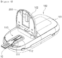
FIG. 1 is a perspective view illustrating an embodiment of a cholesterol measurement device according to the present invention, -
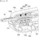
FIG. 2 is an exploded perspective view illustrating an embodiment of the cholesterol measurement device according to the present invention, -
FIG. 3 is a perspective view illustrating an example in which a strip fixation unit is coupled in an embodiment of the cholesterol measurement device according to the present invention, -
FIG. 4 is a cross-sectional view illustrating an embodiment of a measurement unit in an embodiment of the cholesterol measurement device according to the present invention, -
FIG. 5 is a perspective view illustrating an embodiment of the cholesterol measurement device according to the present invention, -
FIGS. 6 and7 are enlarged cross-sectional views illustrating an embodiment of the cholesterol measurement device according to the present invention.FIG. 6 is a cross-sectional view before a measurement strip is inserted and coupled into a strip fixation unit, andFIG. 7 is a cross-sectional view illustrating a state in which the measurement strip is inserted and coupled into the strip fixation unit. -
FIG. 8 is a perspective view illustrating another embodiment of a cholesterol measurement device according to the present invention, and -
FIG. 9 is an exploded perspective view illustrating another embodiment of the cholesterol measurement device according to the present invention. - Hereinafter, the present invention will be described in detail with reference to the accompanying drawings, in which exemplary embodiments of the present invention are shown, so that the person having ordinary skill in the art to which the present invention pertains. However, the present invention may be embodied in many different forms, and is not limited to embodiments described herein. Throughout the specification, like reference numerals refer to like elements.
- In addition, since respective components described in the present invention are all components capable of configuring a cholesterol measurement device of the present invention, the components may be combined without limitations regardless of positions of the components described to configure the cholesterol measurement device of the present invention.
- Referring to
FIGS. 1 to 7 , an embodiment of a cholesterol measurement device according to the present invention includes ameasurement strip 10 and a measuringinstrument body 100 for measuring the quantity of cholesterol in a specimen. - The
measurement strip 10 includes aspecimen input unit 11 for inputting a specimen of blood or serum, and may include a specimen receiving groove for receiving the specimen. The specimen may be collected from venous blood or capillary blood of a subject to be measured, that is, a patient, or may be a serum isolated from the patient's blood. - On the upper surface of the
measurement strip 10, thespecimen input unit 11 is positioned to be input and stored with the specimen, and thespecimen input unit 11 is formed in a groove shape with an open upper surface, so that an inspector may drop the specimen and input the specimen therein. In addition, themeasurement strip 10 may further include a known configuration such as a reaction unit that reacts with the specimen. - The measuring
instrument body 100 includes abody housing member 101, an opening/closingmember 102, and ameasurement window member 120, and thebody housing member 101 includes ameasurement unit 110 and a light-emittingunit 103. The measuringinstrument body 100, specifically, one side of thebody housing member 101 is provided with themeasurement unit 110 in which themeasurement strip 10 is positioned, and the light-emittingunit 103 is provided in the measuringinstrument body 100 to emit light to themeasurement unit 110. - The
measurement unit 110 may be positioned in a recessed form on the measuring instrument body, specifically, one side of thebody housing member 101, and themeasurement window member 120 through which the light emitted from the light-emittingunit 103 may pass may be positioned in themeasurement unit 110. Themeasurement window member 120 may be made of a transparent or translucent material, and may be made of various known materials through which light emitted from the light-emittingunit 103 passes. - The
measurement unit 110 is provided with astrip fixation unit 111 into which themeasurement strip 10 may be inserted and positioned, and themeasurement window member 120 is positioned on the bottom surface at the inner part of thestrip fixation unit 111 and positioned on themeasurement window member 120. When themeasurement strip 10 is inserted and mounted into thestrip fixation unit 111, the light emitted from the light-emittingunit 103 passes through themeasurement strip 10 inserted into thestrip fixation unit 111 to be incident to themeasurement strip 10. - The
strip fixation unit 111 is positioned so that an inlet is open to one side of thebody housing member 101, and themeasurement strip 10 may be inserted while sliding from the inlet. - The light-emitting
unit 103 is positioned inside thebody housing member 101 from the lower side of themeasurement window member 120 and may emit the light toward themeasurement window member 120. The light-emittingunit 103 is an example of a light-emitting diode (LED), and in addition, may be variously modified and implemented into various known lamps used in a color development method that changes the color development of themeasurement strip 10. - In addition, a photodiode unit (PD) for measuring light reflected from the
measurement strip 10 may be positioned inside thebody housing member 101. Themeasurement unit 110 may measure the quantity of cholesterol in the specimen using the intensity of light detected from the photo diode (PD). - The measuring
instrument body 100 may measure the quantity of cholesterol in the specimen by emitting the light from the light-emittingunit 103 to emit the light to themeasurement strip 10 positioned on themeasurement window member 120 through themeasurement window member 120 and then detecting the light reflected from themeasurement strip 10 with the photo diode PD (not illustrated). This is known in the cholesterol measurement device using the color development method, and a more detailed description thereof will be omitted. - The
measurement unit 110 is provided with thestrip fixation unit 111 and a coupling unit for thestrip fixation unit 112, thestrip fixation unit 111 may be inserted with themeasurement strip 10 to be detachably coupled with themeasurement strip 10, and thestrip fixation unit 111 may be inserted and coupled to the coupling unit for thestrip fixation unit 112. The coupling unit for thestrip fixation unit 112 is mounted on the measuringinstrument body 100, specifically, thebody housing member 101, for example, may be integrally formed with thebody housing member 101. - The
strip fixation unit 111 may be integrally formed with the coupling unit for thestrip fixation unit 112 or may be designed to be detachable from the coupling unit for thestrip fixation unit 112. - The specimen of blood or serum is dropped into the
specimen inlet 11 of themeasurement strip 10, and at this time, when the specimen is dropped out of thespecimen inlet 111 or a dose or more of specimen is dropped to thespecimen inlet 11 due to a user's mistake, the specimen contaminates themeasurement unit 110. - In the case where the
strip fixation unit 111 is designed to be detachably coupled to the measuringinstrument body 100, specifically thebody housing member 101, more particularly the coupling unit for thestrip fixation unit 112, when the specimen flows into the inside of thestrip fixation unit 111, themeasurement unit 110 may be easily cleaned by separating thestrip fixation unit 111 so that it may be expected to improve a convenience during the cleaning operation and to keep themeasurement unit 110 clean at all times. - The
strip fixation unit 111 may be formed in, for example, a-shape with an open inlet into which the
measurement strip 10 is inserted. - For example, the
strip fixation unit 111 may include stripside support members 111a which are spaced apart from each other so that themeasurement strip 10 is inserted therebetween and support both sides of themeasurement strip 10, and a strip front-end support member 111b which has both ends connected to one end side of the pair of stripside support members 111a spaced apart from each other, respectively, and supports the front end of themeasurement strip 10. - At this time, the
strip fixation unit 111 is opened in a direction of astrip inlet 102b between the stripside support members 111a, so that themeasurement strip 10 may be inserted and positioned between the stripside support members 111a. - At one side of an outer side of the
measurement strip 10 and an inner side of the stripside support member 111a, a firstslide coupling groove 12 may be positioned, and at the other side of the outer side of themeasurement strip 10 and the inner side of the stripside support member 111a, a firstslide rail unit 111c inserted into the firstslide coupling groove 12 may be positioned to protrude. - As an example, the first
slide coupling groove 12 is formed to have an open front end in an insertion direction at both sides of themeasurement strip 10. In addition, as an example, the firstslide rail unit 111c is positioned on the inner side of the stripside support member 111a. - As the
measurement strip 10 is inserted between the stripside support members 111a, the firstslide rail unit 111c is inserted into the firstslide coupling groove 12 and themeasurement strip 10 slides along the firstslide rail unit 111c to be coupled to thestrip fixation unit 111. Further, themeasurement strip 10 may be separated from thestrip fixation unit 111 while sliding along the firstslide rail unit 111c in a direction opposite to the insertion. - When the
strip fixation unit 111 is designed to be detachable from the coupling unit for thestrip fixation unit 112, the coupling unit for thestrip fixation unit 112 may be formed such that the direction of thestrip inlet 102b is open so that thestrip fixation unit 111 may be inserted. For example, the-shaped fixation insertion space in which the direction of thestrip inlet 102b is opened may be formed in the coupling unit for thestrip fixation unit 112. - As an example, the coupling unit for the
strip fixation unit 112 may include side support members forstrip fixation unit 112a which are spaced apart from each other to support outer sides of the stripside support members 111a of thestrip fixation unit 111, and a front support member forstrip fixation unit 112b which supports an outer side of the strip front-end support member 111b of thestrip fixation unit 111. - A second
slide coupling groove 111d may be positioned at any one side of the inner side of the side support member forstrip fixation unit 112a and the outer side of the stripside support member 111a, and a secondslide rail unit 112c may be positioned at the other side of the inner side of the side support member forstrip fixation unit 112a and the outer side of the stripside support member 111a to slide while being inserted into the secondslide coupling groove 111d. - As an example, the second
slide coupling groove 111d is positioned on the outer side of the stripside support member 111a, and the secondslide rail unit 112c is positioned on the inner side of the side support member forstrip fixation unit 112a. - The outer side of the strip
side support member 111a of thestrip fixation unit 111 and the inner side of the side support member forstrip fixation unit 112a of the coupling unit for thestrip fixation unit 112 may have a spacing of at least 0.01 mm to 2.0 mm, preferably 0.1 mm to 1.5 mm, more preferably 0.3 mm to 1.0 mm. - When the
measurement strip 10 is inserted into thestrip fixation unit 111, the spacing may be filled by the outer side modified by elastically modifying the stripside support member 111a. - A width of the
measurement strip 10 may be formed to be larger than a spacing between the inner sides of the corresponding strip side support members by 0.02 mm to 4.0 mm, preferably 0.2 mm to 3.0 mm, more preferably 0.6 mm to 2.0 mm. - In the conventional cholesterol measurement device, since the spacing is not formed, the modification of the strip fixation unit is likely to occur, and when such a modification of the strip fixation unit occurs, there is a problem in that the fixing position of the measurement strip is changed. That is, when the fixing position of the measurement strip is changed as described above, since a cholesterol measurement value is also changed, this problem acts as a cause that makes it difficult to accurately measure cholesterol.
- However, the structure as described above of the present invention forms a space between the outer side of the strip
side support member 111a of thestrip fixation unit 11 and the inner side of the side support member forstrip fixation unit 112a of the coupling unit for thestrip fixation unit 112 to prevent the modification of thestrip fixation unit 111. When themeasurement strip 10 is inserted into thestrip fixation unit 111, the space is configured to be filled by the outer side of the stripside support member 111a while being elastically modified to perform the cholesterol measurement under predetermined conditions, thereby improving the accuracy of the cholesterol measurement. - A
coupling guide groove 111e may be positioned on any one side of the inner side of the front support member forstrip fixation unit 112b of the coupling unit for thestrip fixation unit 112 and the outer side of the strip front-end support member 111b, and a couplingguide rail unit 112d inserted into thecoupling guide groove 111e may be positioned to protrude from the other side of the inner side of the front support member forstrip fixation unit 112b and the outer side of the strip front-end support member 111b. - For example, the
coupling guide groove 111e is positioned on the outer side of the strip front-end support member 111b, and the couplingguide rail unit 112d is positioned on the inner side of the front support member forstrip fixation unit 112b. - The coupling unit for the
strip fixation unit 112 may further include a strip fixation unit coupling checking switch (112e inFIG. 2 ) which is pressed when thestrip fixation unit 111 is inserted, and installed to check whether the strip fixation unit is coupled. - The
measurement unit 110 may further include afixation locking unit 113 capable of locking the position of thestrip fixation unit 111 coupled to the coupling unit for thestrip fixation unit 112. - The
fixation locking unit 113 may include afirst locking unit 114 positioned at a rear end side of thestrip fixation unit 111 and asecond locking unit 115 positioned at the rear end side of the coupling unit for thestrip fixation unit 112 and positioned and locked with thefirst locking unit 114. - The
second locking unit 115 includes a lockinggroove 115a formed on a lower surface from the rear end side of the coupling unit for thestrip fixation unit 112, and thefirst locking unit 114 may include a wedge-shapedlocking step 114a which is inserted to the lockinggroove 115a at an end side thereof. - In addition, the
first locking unit 114 may include anelastic support member 114b that elastically supports and presses the lockingstep 114a to separate thelocking step 114a from the lockinggroove 115a. - As an example, the
elastic support member 114b is positioned at the other end side of the pair of stripside support members 111a spaced apart from each other so that both ends thereof are connected to each other. - On an upper surface of the
elastic support member 114b, apressing groove 114c indicating a pressing position of theelastic support member 114b may be positioned. - The
elastic support member 114b descends when a portion where thepressing groove 114c is positioned is pressed so that the lockingstep 114a may be separated from the lockinggroove 115a. - The
strip fixation unit 111 is pulled to the rear side while theelastic support member 114b is pressed and the lockingstep 114a is separated from the lockinggroove 115a to be separated from the coupling unit for thestrip fixation unit 112. - That is, the
strip fixation unit 111 is inserted into a fixation insertion space, and slides to be coupled to the coupling unit for thestrip fixation unit 112 until the couplingguide rail unit 112d is inserted into thecoupling guide groove 111e while the secondslide rail unit 112c is inserted into the secondslide coupling groove 111d and slides. - At this time, the
elastic support member 114b may be locked when the wedge-shaped locking step114a is naturally inserted into the lockinggroove 115a. - When pressing the portion where the
pressing groove 114c is positioned in theelastic support member 114b, the lockingstep 114a is separated from the lockinggroove 115a, and while the lockingstep 114a is separated from the lockinggroove 115a, when thestrip fixation unit 111 is pulled toward the rear side of the fixation insertion space, thestrip fixation unit 111 may be simply separated from the coupling unit for thestrip fixation unit 112. - The measuring
instrument body 100 may further include a light-intensity check member 200 which reflects the light emitted from the light-emittingunit 103 to check whether the intensity of light is abnormal. In this case, the light-intensity check member 200 may be mounted and provided integrally with the measuringinstrument body 100, specifically the opening/closingmember 102. - The opening/closing
member 102 may open and close themeasurement unit 110 and may be rotatably coupled to thebody housing member 101. As an example, the opening/closingmember 102 is rotatably coupled to thebody housing member 101 with a hinge portion and rotated around the hinge portion to open and close themeasurement unit 110. - The opening/closing
member 102 has a size and a shape capable of covering themeasurement unit 110 and may be formed to have a height corresponding to the height of the recessedmeasurement unit 110. - The light-
intensity check member 200 reflects the light emitted through the light-emittingunit 103 so as to check the light intensity of the light-emittingunit 103. The light-intensity check member 200 may be positioned on the lower surface of the opening/closingmember 102, and is positioned to correspond to themeasurement window member 120 when the opening/closingmember 102 is closed so that the light of the light-emittingunit 103 passing through themeasurement window member 120 may be emitted. - As an example, the light-
intensity check member 200 has a specific gray value capable of measuring the intensity of LED light by reflection, and in addition, the light-intensity check member 200 may be modified into a variety of known colors so as to measure the intensity of light by reflecting the light emitted from the light-emittingunit 103. - The measuring
instrument body 100 may further include aspring member 300, and thespring member 300 is positioned between the light-intensity check member 200 and the opening/closingmember 102 so that the light-intensity check member 200 may be in close contact with themeasurement window member 120 in the state where the opening/closingmember 102 is closed. - As an example, the
spring member 300 is a coil spring, and a portion of the lower end side of thespring member 300 may be coupled to the upper surface of the light-intensity check member 200. For example, a plurality ofspring insertion units 210 for guiding a vertical movement of thespring member 300 may be provided on the upper surface of the light-intensity check member 200, and in this case, thespring member 300 may be inserted and positioned into thespring insertion units 210. For example, the plurality ofspring insertion units 210 may be partitioned by a plurality of partition walls formed on the upper surface of the light-intensity check member 200, and the plurality of partition walls may be spaced apart from each other to guide the vertical movement of thespring member 300. - Further, a plurality of spring
fitting units 102a into which a portion of the upper end side of thespring member 300 is fitted may be positioned on the lower surface of the opening/closingmember 102. - An upper end side of the
spring member 300 is fitted and coupled into the springfitting unit 102a, and a portion at the lower end side of thespring member 300 is inserted into thespring insertion units 210 so that restoration by compression and elastic restoring force may be stably repeated. - As an example, the light-
intensity check member 200 may be formed in a block shape having a flat lower surface that may be in close contact with themeasurement window member 120 and has an area covering the front surface of themeasurement window member 120. - The block shape has the flat lower surface that may be in close contact with the
measurement window member 120, and is not particularly limited so long as the shape is a shape capable of measuring the intensity of light by uniformly reflecting the light emitted from the light-emittingunit 103. Specifically, for example, plate shapes such as a square plate, polygonal column shapes such as a square column shape, etc. may be included. In the case of the polygonal column shape, the direction of the lower surface of the opening/closingmember 102 may be opened so that the spring may be stably interposed therebetween. - In the state where the opening/closing
member 102 is closed, the light-intensity check member 200 is elastically supported by thespring member 300 to be positioned in close contact with themeasurement window member 120, thereby accurately measuring the light intensity of the light-emittingunit 103. In addition, themeasurement strip 10 comes into close contact with themeasurement window member 120 and the position of themeasurement strip 10 is fixed by pressing themeasurement strip 10 positioned on themeasurement window member 120, thereby more stably and accurately measuring the quantity of cholesterol. - At one side of the opening/closing
member 102, thestrip inlet 102b may be positioned to be opened so that themeasurement strip 10 passes through thestrip inlet 102b to be inserted between the light-intensity check member 200 and themeasurement window member 120. - The
strip inlet 102b is positioned to coincide with the opened inlet at the rear side of thestrip fixation unit 111 and themeasurement strip 10 is inserted into thestrip fixation unit 111 through the inlet of thestrip fixation unit 111 and thestrip inlet 102b in the state where the opening/closingmember 102 is closed to be positioned between the light-intensity check member 200 and themeasurement window member 120. - The light-
intensity check member 200 may have an inclined surface capable of guiding the insertion of themeasurement strip 10 at the front end side positioned toward thestrip inlet 102b. - When the
measurement strip 10 is inserted into thestrip fixation unit 111 through the inlet of thestrip fixation unit 111 and thestrip inlet 102b in the state where the opening/closingmember 102 is closed, the light-intensity check member 200 elevates while compressing thespring member 300 to insert themeasurement strip 10 into thestrip fixation unit 111. - The light-
intensity check member 200 may naturally elevate while the end side of themeasurement strip 10 is inserted while pushing the inclined surface to insert and position themeasurement strip 10 into thestrip fixation unit 111. - That is, even while the opening/closing
member 102 is closed, themeasurement strip 10 may be positioned into thestrip fixation unit 111, and themeasurement strip 10 positioned into thestrip fixation unit 111 may be pressed by the block-shaped light-intensity check member 200 to be stably positioned while coming into close contact with themeasurement window member 120 in the measurement insertion unit. - Meanwhile, the cholesterol measurement device according to the present invention may include a light-intensity abnormality checking unit (not illustrated) which operates the light-emitting
unit 103 to emit the light to the light-intensity check member 200 and checks whether the light-emittingunit 103 is abnormal, that is, whether the intensity of light is abnormal by the light reflected by the light-intensity check member 200. - The light-intensity abnormality checking unit may operate the light-emitting
unit 103 to emit the light to the light-intensity check member 200 before the light-intensity check member 200 is in close contact with themeasurement window member 120, that is, themeasurement strip 10 is inserted and coupled to thestrip fixation unit 111 and check whether the light-emittingunit 103 is abnormal, that is, whether the intensity of light is abnormal by the light reflected by the light-intensity check member 200. - Meanwhile, the measuring
instrument body 100 includes a real time clock (RTC), and the light-intensity abnormality checking unit (not illustrated) may check whether a date has changed when power is turned ON, operate the light-emittingunit 103 when the date is changed to emit the light to the light-intensity check member 200, and check whether the light-emittingunit 103 is abnormal, that is, whether the intensity of light is abnormal by the light reflected by the light-intensity check member 200. - The light-intensity abnormality checking unit may first operate the light-emitting
unit 103 when the power of the measuringinstrument body 100 is turned on to emit the light to the light-intensity check member 200, measure a reflection value reflected by the light-intensity check member 200, and store an initial reflection value. - In addition, when the power is repeatedly turned on for the use of the measuring
instrument body 100, the light-intensity abnormality checking unit may check the date with the RTC whenever the power is turned on, operate the light-emittingunit 103 when the date is changed to emit the light to the light-intensity check member 200, and check whether the light intensity of the light-emittingunit 103 is abnormal by compare the reflection value reflected by the light-intensity check member 200 with the initial reflection value. - In addition, the light-intensity abnormality checking unit includes a light-intensity abnormality notification unit that notifies the outside when it is checked that the light intensity of the light-emitting
unit 103 is abnormal to re-control the light intensity of the light-emittingunit 103. - That is, while the light-
intensity check member 200 is maintained in a state that is always mounted on the measuringinstrument body 100 and the opening/closingmember 102 is closed, when the power of the measuringinstrument body 100 is turned on, the light-intensity abnormality checking unit automatically checks whether the light intensity of the light-emittingunit 103 is abnormal, thereby securing the accuracy and reliability of the cholesterol measurement. - The light-
intensity check member 200 is provided integrally with the measuringinstrument body 100 by changing the check strip of checking whether the light intensity is abnormal into the block shape to have no fear of loss and solve an inconvenience to store the check strip separately, thereby improving a convenience in use. - When the light-
intensity check member 200 inspects whether the light intensity is abnormal, it is possible to solve the problems caused by a deviation in the check strip, accurately confirm a change in light intensity to prevent a change in measurement value according to the change in light intensity, and improve the reliability to the measurement value. - The light-intensity abnormality checking unit automatically checks everyday whether the light intensity is abnormal to ensure the accuracy and reliability for cholesterol measurement.
-
FIG. 8 is a perspective view illustrating another embodiment of a cholesterol measurement device according to the present invention andFIG. 9 is an exploded perspective view illustrating another embodiment of the cholesterol measurement device according to the present invention. - Referring to
FIGS. 8 and 9 , the cholesterol measurement device according to the present invention may further include aprinter body 400 which is detachably coupled with the measuringinstrument body 100 and electrically connected with the measuringinstrument body 100 to print a result of cholesterol measurement values measured by the measuringinstrument body 100. - The
printer body 400 may include a printer unit which receives the result of the cholesterol measurement values measured by the measuringinstrument body 100 and outputs the result on paper, and a rechargeable battery that supplies electric power to the printer unit. - The printer unit is a known configuration in a known printer device, and a more detailed description thereof will be omitted.
- In the
printer body 400, a charging terminal (not illustrated) which is connected with a charging cable to charge the rechargeable battery is positioned, and the charging terminal may be variously modified and implemented using known terminals such as a USB terminal, a micro 5-pin terminal, etc. - The
printer body 400 may be used even while carrying by including the rechargeable battery, and may output the result of the cholesterol measurement values easily even in places where power connection is disabled. - In the
printer body 400, a measuringinstrument seating unit 410 on which the measuringinstrument body 100 is seated is positioned, and in the measuringinstrument seating unit 410, a measuring instrumentconnection terminal unit 420 may be positioned to be electrically connected with the measuringinstrument body 100 seated in the measuringinstrument seating unit 410. - In addition, in the measuring
instrument body 100, a printerconnection terminal unit 130 may be positioned to be electrically connected to the measuring instrumentconnection terminal unit 420 to be electrically connected with theprinter body 400. - When the measuring
instrument body 100 is seated on the measuringinstrument seating unit 410, the printerconnection terminal unit 130 is connected with the measuring instrumentconnection terminal unit 420 to be electrically connected with the measuringinstrument body 100, theprinter body 400 may receive and output the result of the cholesterol measurement values from the measuringinstrument body 100. - In the measuring
instrument seating unit 410, a lockingmember 430 for locking and fixing the measuringinstrument body 100 is positioned to protrude, and on the lower surface of the measuringinstrument body 100, the firstlocking insertion unit 140 into which the lockingmember 430 is inserted and locked may be positioned. - The locking
member 430 has a-shaped shape and is positioned to protrude on the measuring
instrument seating unit 410, and a secondlocking insertion unit 150 into which a bent end side of the lockingmember 430 is inserted may be positioned in the firstlocking insertion unit 140. - In addition, in the measuring
instrument seating unit 410, a movingmember 411 may be positioned to support the rear end of the measuringinstrument body 100 and be pushed toward the rear end of the measuringinstrument body 100, and be elastically supported to return to its original position. - The moving
member 411 is moved to the rear side of the measuringinstrument body 100 while the measuringinstrument body 100 is positioned on the measuringinstrument seating unit 410 so that the lockingmember 430 may be removed and separated from the firstlocking insertion unit 140. - The locking
member 430 may be positioned such that the- shaped bent end side faces the rear side, and the secondlocking insertion unit 150 may be positioned on the rear surface in the firstlocking insertion unit 140. - In addition, as an example, the printer
connection terminal unit 130 is positioned at the front end side from the lower surface of the measuringinstrument body 100, and the measuring instrumentconnection terminal unit 420 is positioned at a moving unit. - The measuring
instrument body 100 is seated on the measuringinstrument seating unit 410 so that while the printerconnection terminal unit 130 and the measuring instrumentconnection terminal unit 420 are electrically connected to each other, the end portion that is bent while the lockingmember 430 is inserted into the firstlocking insertion unit 140 is inserted and locked into the secondlocking insertion unit 150 to be coupled with theprinter body 400. - That is, while the measuring
instrument body 100 is seated on the measuringinstrument seating unit 410, the end portion that is bent while the lockingmember 430 is inserted into the firstlocking insertion unit 140 is inserted and locked into the secondlocking insertion unit 150 to be firmly coupled with theprinter body 400 and to be prevented from being separated. - In addition, when the measuring
instrument body 100 is separated from theprinter body 400, the measuringinstrument body 100 is pushed to the rear side, the movingmember 411 moves to the rear side, and then the bent end portion of the lockingmember 430 inserted into the secondlocking insertion unit 150 is removed from the lockinginsertion unit 150 to be easily separated from theprinter body 400 by lifting the measuringinstrument body 100. - According to the present invention, it is possible to have no fear of loss and solve an inconvenience to store a check strip separately to improve convenience in use by changing a check strip of confirming whether the quality of light is abnormal into a block shape to be provided integrally with the measuring
instrument body 100. - According to the present invention, it is possible to solve the problems caused by a deviation in a check strip when the light-
intensity check member 200 of confirming whether the quality of LED light is abnormal is integrally provided to inspect whether the light quality is abnormal, accurately confirm a change in light intensity to prevent a change in measurement value according to the change in light intensity, and improve the reliability to the measurement value. - According to the present invention, it is possible to ensure the accuracy and reliability for cholesterol measurement by automatically confirming everyday whether the light intensity is abnormal.
- According to the present invention, it is possible to greatly improve a convenience in use by including a printer which is detachable from the measuring
instrument body 100 and portable to output a measurement value directly in use and confirm the measurement value. - According to the present invention, it is possible to improve a convenience during cleaning and keep the measurement unit clean at all times by separating the strip fixation unit when a specimen flows into the strip fixation unit into which the measurement strip is inserted to easily clean the measurement unit.
- According to the present invention, it is possible to improve the accuracy of the measurement value when measuring cholesterol and secure the reliability of the measurement value by easily cleaning the measurement unit.
- According to the present invention, it is possible to greatly improve a convenience in use by including a printer which is detachable from the measuring instrument body and portable to output a measurement value directly in use and confirm the measurement value.
- While the preferred embodiment of the present invention has been described in detail, the scope of the present invention is not limited thereto, and various modifications and variations of those skilled in the art using basic concepts of the present invention which have been defined in the appended claims cover the scope of the present invention.
-
10: Measurement strip 11: Specimen input unit 12: First slide coupling groove 100: Measuring instrument body 101: Body housing member 102: Opening/closing member 103: Light-emitting unit 102a: Spring fitting unit 102b: Strip inlet 110: Measurement unit 111: Strip fixation unit 111a: Strip side support member 111b: Strip front- end support member 111c: First slide rail unit 111d: Second slide coupling groove 12: Coupling unit for the strip fixation unit 12a: Side support member for strip fixation unit 12b: Front support member for strip fixation unit 112c: Second slide rail unit 2d: Coupling guide rail unit 112e: Strip fixation unit coupling checking switch 113: Fixation locking unit 114: First locking unit 114a: Locking step 114b: Elastic support member 114c: Pressing groove 115: Second locking unit 115a: Locking groove 120: Measurement window member 130: Printer connection terminal unit 140: First locking insertion unit 150: Second locking insertion unit 200: Light-intensity check member 210: Spring insertion unit 300: Spring member 400: Printer body 410: Measuring instrument seating unit 411: Moving member 420: Measuring instrument connection terminal unit 430: Locking member
Claims (15)
- A cholesterol measurement device comprising:a measuring instrument body which includes a measurement unit where a measurement strip is positioned and a light-emitting unit emitting light to the measurement unit and detects the intensity of light reflecting after emitting the light to the measurement strip to measure the quantity of cholesterol; anda light-intensity check member which is mounted and integrally provided on the measuring instrument body and reflects the light emitted from the light-emitting unit to check whether the intensity of light is abnormal.
- The cholesterol measurement device of claim 1, wherein the light-intensity check member has a block shape having a flat lower surface.
- The cholesterol measurement device of claim 1, further comprising:
a spring member elastically supporting the light-intensity check member. - The cholesterol measurement device of claim 1, wherein a measurement window member through which the light emitted from the light-emitting unit passes is positioned in the measurement unit, and
the light-intensity check member is elastically supported by the spring member to be positioned in close contact with the measurement window member. - The cholesterol measurement device of claim 1, wherein the measuring instrument body includesa body housing member of which the measurement unit where the measurement strip is positioned is provided at one side and the light-emitting unit emitting the light to the measurement unit is provided therein; andan opening/closing member opening and closing the measurement unit, andthe light-intensity check member is positioned on a lower surface of the opening/closing member.
- The cholesterol measurement device of claim 5, wherein a measurement window member through which the light emitted from the light-emitting unit passes is positioned in the measurement unit, and the light-intensity check member is elastically supported by a spring member in the state where the opening/closing member is closed, and is positioned in close contact with the measurement window member.
- The cholesterol measurement device of claim 6, wherein a strip inlet is positioned at one side of the opening/closing member so that the measurement strip can be inserted between the light-intensity check member and the measurement window member in the state where the opening/closing member is closed, and
the light-intensity check member has an inclined surface which is positioned at a front end side positioned toward the strip inlet to guide the insertion of the measurement strip. - The cholesterol measurement device of claim 1, wherein the measuring instrument body includes a real time clock (RTC), and includes a light-intensity abnormality checking unit which checks whether a date has changed when power is turned ON, operates the light-emitting unit when the date is changed to emit the light to the light-intensity check member, and checks whether the light-emitting unit is abnormal by the light reflected by the light-intensity check member.
- The cholesterol measurement device of claim 1, wherein the measurement unit includes a strip fixation unit to which the measurement strip is inserted and detachably coupled, which is detachable from the measuring instrument body; and a coupling unit for the strip fixation unit which is mounted and positioned on the measuring instrument body and is detachably coupled with the strip fixation unit; wherein the measurement unit is capable of cleaning.
- The cholesterol measurement device of claim 9, wherein the strip fixation unit includesstrip side support members which are spaced apart from each other so that the measurement strip is inserted therebetween and support both sides of the measurement strip; anda strip front-end support member which has both end sides which are connected to one end side of the pair of the spaced strip side support members and supports a front-end of the measurement strip,wherein a first slide coupling groove is positioned in a longitudinal direction at any one side of an outer side of the measurement strip and an inner side of the strip side support member, and a first slide rail unit inserted into the first slide coupling groove is positioned to protrude at the other side of the outer side of the measurement strip and the inner side of the strip side support member.
- The cholesterol measurement device of claim 10, wherein the coupling unit for the strip fixation unit includesside support members for strip fixation unit spaced apart from each other to support the outer sides of the strip side support members of the strip fixation unit; and a front support member for strip fixation unit supporting the outer side of the strip front-end support member,wherein a second slide coupling groove is positioned at any one side of an inner side of the side support member for strip fixation unit and an outer side of the strip side support member, and a second slide rail unit is positioned at the other side of the inner side of the side support member for strip fixation unit and the outer side of the strip side support member to be inserted into the second slide coupling groove and slides.
- The cholesterol measurement device of claim 11, wherein the outer side of the strip side support member of the strip fixation unit and the inner side of the side support member for strip fixation unit of the coupling unit for the strip fixation unit have a spacing of at least 0.01 mm to 2.0 mm, and
the spacing is filled by the outer side of the strip side support member while the strip side support member is elastically modified when the measurement strip is inserted into the strip fixation unit. - The cholesterol measurement device of claim 11, wherein a coupling guide groove is positioned at any one side of the inner side of the front support member for strip fixation unit of the coupling unit for the strip fixation unit and the outer side of the strip front-end support member of the strip fixation unit, and a coupling guide rail unit inserted into the coupling guide groove is positioned to protrude at the other side of the inner side of the front support member for strip fixation unit and the outer side of the strip front-end support member.
- The cholesterol measurement device of claim 9, wherein the measurement unit further includes a fixation locking unit capable of locking the position of the strip fixation unit coupled to the coupling unit for the strip fixation unit.
- The cholesterol measurement device of claim 14, wherein the fixation locking unit includesa first locking unit positioned at the rear end side of the strip fixation unit; anda second locking unit positioned at the rear end side of the coupling unit for the strip fixation unit and positioned to be locked with the first locking unit.
Applications Claiming Priority (3)
| Application Number | Priority Date | Filing Date | Title |
|---|---|---|---|
| KR1020180136874A KR102140768B1 (en) | 2018-11-08 | 2018-11-08 | Apparatus for Measuring Cholesterol |
| KR20180136792 | 2018-11-08 | ||
| PCT/KR2019/015066 WO2020096373A1 (en) | 2018-11-08 | 2019-11-07 | Cholesterol measurement device |
Publications (2)
| Publication Number | Publication Date |
|---|---|
| EP3879256A1 true EP3879256A1 (en) | 2021-09-15 |
| EP3879256A4 EP3879256A4 (en) | 2022-08-10 |
Family
ID=70611364
Family Applications (1)
| Application Number | Title | Priority Date | Filing Date |
|---|---|---|---|
| EP19882842.8A Pending EP3879256A4 (en) | 2018-11-08 | 2019-11-07 | Cholesterol measurement device |
Country Status (4)
| Country | Link |
|---|---|
| US (1) | US20210341465A1 (en) |
| EP (1) | EP3879256A4 (en) |
| CN (1) | CN112997066A (en) |
| WO (1) | WO2020096373A1 (en) |
Cited By (1)
| Publication number | Priority date | Publication date | Assignee | Title |
|---|---|---|---|---|
| EP4202411A1 (en) * | 2021-12-27 | 2023-06-28 | Osang Healthcare Co., Ltd. | Measurement device with light quantity correction function and light quantity correction method thereof |
Family Cites Families (21)
| Publication number | Priority date | Publication date | Assignee | Title |
|---|---|---|---|---|
| DE8411914U1 (en) * | 1984-04-16 | 1984-08-23 | LRE Relais + Elektronik GmbH, 8000 München | Remission photometer for the evaluation of test paper strips |
| JPH0650311B2 (en) * | 1985-07-09 | 1994-06-29 | オムロン株式会社 | Biochemical measuring device |
| JPH079069Y2 (en) * | 1987-11-24 | 1995-03-06 | オムロン株式会社 | Reflector for blank value measurement of biochemical measuring instrument |
| JP3424009B2 (en) * | 1994-08-02 | 2003-07-07 | アークレイ株式会社 | Sample component analyzer using test paper |
| DE69524108T2 (en) * | 1994-09-08 | 2002-06-06 | Lifescan Inc | ANALYTIC DETECTION STRIP WITH A STANDARD ON THE STRIP |
| JP3324339B2 (en) * | 1995-05-25 | 2002-09-17 | 株式会社サタケ | Spectroscopic analyzer |
| US6239445B1 (en) * | 1999-03-01 | 2001-05-29 | Bayer Corporation | Optical inspection apparatus with removable inserts |
| JP2004347436A (en) * | 2003-05-21 | 2004-12-09 | Terumo Corp | Component measuring device |
| US7118713B2 (en) * | 2003-06-03 | 2006-10-10 | Bayer Healthcare Llc | Tray assembly for optical inspection apparatus |
| DE102007009784A1 (en) * | 2007-02-27 | 2008-08-28 | opTricon Entwicklungsgesellschaft für optische Technologien GmbH | Device for evaluating test sample, particularly medical test sample, has radiation source for generating electromagnetic radiation, measuring instrument for measuring reflected radiation from test sample and evaluator |
| JP2010521266A (en) * | 2007-03-23 | 2010-06-24 | エンフェルディス ゲーエムベーハー | Noninvasive continuous measurement of blood component concentration |
| US20160370366A1 (en) * | 2010-07-20 | 2016-12-22 | Quantrx Biomedical Corporation | Optical reader systems and lateral flow assays |
| KR101144830B1 (en) * | 2010-09-10 | 2012-05-11 | 주식회사 세라젬메디시스 | Assay apparatus |
| US20140271362A1 (en) * | 2013-03-12 | 2014-09-18 | Robert J. Markovsky | Recognition test strips |
| KR101530938B1 (en) * | 2013-11-08 | 2015-06-25 | (주) 솔 | Light-sensing sensor device with error correction function |
| EP3077798B1 (en) * | 2013-12-06 | 2022-06-22 | Quidel Corporation | Method for reducing analyzer variability using a normalization target |
| KR102307302B1 (en) | 2015-01-09 | 2021-09-30 | 엘지전자 주식회사 | Apparatus and method for measuring cholesterol |
| CN105302232A (en) * | 2014-06-04 | 2016-02-03 | 振桦电子股份有限公司 | Tablet computer with detachable handle |
| KR102331794B1 (en) | 2017-06-15 | 2021-11-26 | 현대두산인프라코어(주) | Construction machine |
| JP7038494B2 (en) | 2017-06-15 | 2022-03-18 | ルネサスエレクトロニクス株式会社 | Solid-state image sensor |
| KR102034093B1 (en) * | 2017-11-22 | 2019-10-18 | 한국기술교육대학교 산학협력단 | Assembled pretreatment apparatus, measurement system and method for on-site measurement of specific heavy metal contamination in soils |
-
2019
- 2019-11-07 EP EP19882842.8A patent/EP3879256A4/en active Pending
- 2019-11-07 CN CN201980073685.3A patent/CN112997066A/en active Pending
- 2019-11-07 US US17/287,370 patent/US20210341465A1/en active Pending
- 2019-11-07 WO PCT/KR2019/015066 patent/WO2020096373A1/en unknown
Cited By (1)
| Publication number | Priority date | Publication date | Assignee | Title |
|---|---|---|---|---|
| EP4202411A1 (en) * | 2021-12-27 | 2023-06-28 | Osang Healthcare Co., Ltd. | Measurement device with light quantity correction function and light quantity correction method thereof |
Also Published As
| Publication number | Publication date |
|---|---|
| EP3879256A4 (en) | 2022-08-10 |
| WO2020096373A1 (en) | 2020-05-14 |
| US20210341465A1 (en) | 2021-11-04 |
| CN112997066A (en) | 2021-06-18 |
Similar Documents
| Publication | Publication Date | Title |
|---|---|---|
| US11231411B2 (en) | Mobile device multi-analyte testing analyzer for use in medical diagnostic monitoring and screening | |
| JP5579968B2 (en) | Specimen dispenser | |
| US7964147B2 (en) | Hand-held analysis device | |
| US7313257B2 (en) | Handheld optical diagnostic device having image system array | |
| WO2005001444A1 (en) | Verification device and method for optical inspection machine | |
| JPH075109A (en) | Test-carrier analysis system | |
| JP2008224667A (en) | Method of dispensing test strip | |
| CN112740035A (en) | Lateral flow assay device and method of use | |
| JP5801004B2 (en) | Calibration method for reagent card analyzer | |
| JP2008517297A (en) | Cartridge for holding and dispensing test sensors | |
| EP3879256A1 (en) | Cholesterol measurement device | |
| KR20120026821A (en) | Assay apparatus | |
| US20080186499A1 (en) | Verification Apparatus and Methods For Optical Inpection Machine | |
| EP2367004B1 (en) | Optical measurement device | |
| KR102140768B1 (en) | Apparatus for Measuring Cholesterol | |
| JP2009074801A (en) | Excessive liquid suction mechanism and chemical analyzer | |
| EP4166077A1 (en) | Apparatus for improving usability and accuracy for physiological measurement | |
| JP2009079926A (en) | Test paper conveyance mechanism and chemical analyzer | |
| CN106574921B (en) | Sensor clip for stacked sensor dispensing system and system using same | |
| US20060257284A1 (en) | Verification device and method for optical inspection machine | |
| KR101929689B1 (en) | Port assembly for mobile medical apparatus | |
| JPS607345A (en) | Atomic-absorption spectrophotometer | |
| JP2005189034A (en) | Pipette device and analyzer equipped with the same | |
| CN219871365U (en) | Tray for parallel processing of multiple test devices | |
| WO2024091661A1 (en) | Apparatus and methods for assaying a liquid sample |
Legal Events
| Date | Code | Title | Description |
|---|---|---|---|
| STAA | Information on the status of an ep patent application or granted ep patent |
Free format text: STATUS: THE INTERNATIONAL PUBLICATION HAS BEEN MADE |
|
| PUAI | Public reference made under article 153(3) epc to a published international application that has entered the european phase |
Free format text: ORIGINAL CODE: 0009012 |
|
| STAA | Information on the status of an ep patent application or granted ep patent |
Free format text: STATUS: REQUEST FOR EXAMINATION WAS MADE |
|
| 17P | Request for examination filed |
Effective date: 20210428 |
|
| AK | Designated contracting states |
Kind code of ref document: A1 Designated state(s): AL AT BE BG CH CY CZ DE DK EE ES FI FR GB GR HR HU IE IS IT LI LT LU LV MC MK MT NL NO PL PT RO RS SE SI SK SM TR |
|
| DAV | Request for validation of the european patent (deleted) | ||
| DAX | Request for extension of the european patent (deleted) | ||
| A4 | Supplementary search report drawn up and despatched |
Effective date: 20220708 |
|
| RIC1 | Information provided on ipc code assigned before grant |
Ipc: G01N 33/92 20060101ALI20220704BHEP Ipc: G01N 21/47 20060101ALI20220704BHEP Ipc: G01N 21/25 20060101AFI20220704BHEP |
|
| STAA | Information on the status of an ep patent application or granted ep patent |
Free format text: STATUS: EXAMINATION IS IN PROGRESS |
|
| 17Q | First examination report despatched |
Effective date: 20230803 |