EP3879195A1 - Lüftungskanalmodul, lüftungssystem, gebäudewand - Google Patents
Lüftungskanalmodul, lüftungssystem, gebäudewand Download PDFInfo
- Publication number
- EP3879195A1 EP3879195A1 EP21161792.3A EP21161792A EP3879195A1 EP 3879195 A1 EP3879195 A1 EP 3879195A1 EP 21161792 A EP21161792 A EP 21161792A EP 3879195 A1 EP3879195 A1 EP 3879195A1
- Authority
- EP
- European Patent Office
- Prior art keywords
- module
- ventilation duct
- wall
- connection
- ventilation
- Prior art date
- Legal status (The legal status is an assumption and is not a legal conclusion. Google has not performed a legal analysis and makes no representation as to the accuracy of the status listed.)
- Granted
Links
Images



Classifications
-
- F—MECHANICAL ENGINEERING; LIGHTING; HEATING; WEAPONS; BLASTING
- F24—HEATING; RANGES; VENTILATING
- F24F—AIR-CONDITIONING; AIR-HUMIDIFICATION; VENTILATION; USE OF AIR CURRENTS FOR SCREENING
- F24F13/00—Details common to, or for air-conditioning, air-humidification, ventilation or use of air currents for screening
- F24F13/02—Ducting arrangements
- F24F13/0227—Ducting arrangements using parts of the building, e.g. air ducts inside the floor, walls or ceiling of a building
-
- F—MECHANICAL ENGINEERING; LIGHTING; HEATING; WEAPONS; BLASTING
- F24—HEATING; RANGES; VENTILATING
- F24F—AIR-CONDITIONING; AIR-HUMIDIFICATION; VENTILATION; USE OF AIR CURRENTS FOR SCREENING
- F24F7/00—Ventilation
- F24F7/04—Ventilation with ducting systems, e.g. by double walls; with natural circulation
-
- F—MECHANICAL ENGINEERING; LIGHTING; HEATING; WEAPONS; BLASTING
- F24—HEATING; RANGES; VENTILATING
- F24F—AIR-CONDITIONING; AIR-HUMIDIFICATION; VENTILATION; USE OF AIR CURRENTS FOR SCREENING
- F24F7/00—Ventilation
- F24F2007/0025—Ventilation using vent ports in a wall
-
- F—MECHANICAL ENGINEERING; LIGHTING; HEATING; WEAPONS; BLASTING
- F24—HEATING; RANGES; VENTILATING
- F24F—AIR-CONDITIONING; AIR-HUMIDIFICATION; VENTILATION; USE OF AIR CURRENTS FOR SCREENING
- F24F2221/00—Details or features not otherwise provided for
- F24F2221/20—Details or features not otherwise provided for mounted in or close to a window
Definitions
- the invention relates to a ventilation duct module according to the preamble of claim 1.
- the invention relates to a ventilation system according to claim 18.
- the invention relates to a building wall according to claim 19.
- Ventilation systems for ventilating buildings are known. Such ventilation systems can remove and / or supply air.
- a connection between a living room on the inside of a building wall and an outside area on the outside of a building wall must be guaranteed.
- a wall duct is implemented through the building wall with a hole or a similar cutout.
- a duct, in particular a duct, and / or a ventilation device is integrated within the wall duct.
- closures e.g. weather protection hoods or designer interior closures
- the closures for the outside area are often visible on the facade of the building. This visibility is often not desired.
- the window frames are often built in abutment with the clinker brick. If a soffit channel is to be installed here, it must be integrated within the outer wall layer, in particular within the clinker brick.
- the outer wall layer, in particular the clinker bricks, have to be tapered in the area of the soffit canal. Often an installation is not even possible due to the geometry of the reveal channel.
- Such a taper weakens the wall outer layer, in particular the clinker wall, especially structurally.
- Weather conditions such as wind loads and showers, can cause damage to the outer wall layer, in particular to the clinker brick wall.
- a tapering of the outer wall layer, especially the clinker bricks, should therefore be avoided.
- the object of which is to provide an improved ventilation duct module and ventilation system which at least partially eliminates the problems prevailing in the prior art.
- the aim is to enable air to be conducted through the building wall, which meets both optical / aesthetic requirements and also reduces structural weakening of an outer wall layer, in particular a clinker brick wall, of a building.
- the object is achieved by the invention with a ventilation duct module of claim 1.
- the invention is based on a ventilation duct module for a soffit duct, for installation in a building wall with a soffit, having a flow duct which connects a soffit connection and a duct connection to one another in an air-conducting direction,
- a small module depth of the ventilation duct module is achieved.
- a small module depth advantageously enables the reveal channel to be integrated into the building wall, which causes only a relatively slight weakening of the outer wall layer, in particular the clinker brick wall.
- the outer wall layer is a clinker brick wall.
- An offset of the air flow direction normal to the building wall means that the design and arrangement of the flow channel causes the air flow guided through the ventilation channel module to be offset between two levels, in particular parallel to the building wall, namely from a level in which the duct connection is located to a level, in which the reveal connection is located.
- the air flow direction does not have to be perpendicular to the building wall.
- the flow channel is arranged parallel to the reveal side or at a channel angle to the reveal side, which is preferably less than or equal to 45 °, particularly preferably less than or equal to 40 °.
- the module depth extends perpendicular to the reveal side between the reveal side and an opposite module back.
- the outer wall layer is a clinker brick wall.
- the ventilation guidance direction describes the flow of the air flowing through the ventilation duct module and lies in the middle of the duct cross-section.
- the clinker format namely the clinker length, the clinker width, and the clinker height is based in particular on the normal format (NF), in which the clinker length is 240 mm, the clinker width 115 mm and the clinker height 71 mm.
- the strenght the mortar layer and thus the distance between two clinker bricks is in particular 10 mm.
- other clinker formats and / or mortar layers in accordance with DIN 1053 and / or DIN 105 and / or EN 771 are possible within the scope of the invention.
- a clinker height includes, in particular, a mortar layer.
- the ventilation duct module has a module depth that is less than or equal to 120 mm, particularly preferably less than or equal to 110 mm, the module depth extending perpendicular to the reveal side between the reveal side and an opposite module rear side.
- Such a further development takes into account the fact that the closure of a clinker wall in front of the reveal is usually formed from solid clinker bricks and clinker bricks halved in their clinker length, alternating in layers.
- a width of 120 mm is usually half a clinker length, that is, half the length of a clinker brick.
- the module depth is half a clinker length or less, only the full clinker bricks have to be tapered and / or notched, and the half clinker bricks can be completely halved along their longitudinal axis to half a clinker width, which advantageously reduces the workload.
- the ventilation duct module in particular has a module depth which is designed to be relatively small, in particular half a clinker width, for example less than or equal to 110 mm.
- the ventilation duct module has in particular a module width which is composed of a duct connection width, which describes the width of the duct connection, and a module core width.
- the duct connection width is in particular less than or equal to 70 mm and can advantageously be adapted to the width of the soffit duct.
- the module core width can in particular be adapted to the offset to be bridged in the ventilation guidance direction and can in particular be 106 mm.
- an outer area width of the module outer area is half, preferably one third, of a module width, the module width extending parallel to the reveal side between the module outer side and the module inner side.
- an inner area width of the module inner area is half, preferably one third, of a module width.
- the flow channel runs at a channel angle to the reveal side that is less than or equal to 40 °.
- the channel angle is preferably less than or equal to 20 °, and the channel angle is particularly preferably less than or equal to 10 °.
- the flow channel has a vertically elongated channel cross section (AKQ), in particular a height-to-width ratio of at least 8 to 1 - also vertically elongated - reveal surface. Due to the correspondingly greater height, despite the small width of the cross-section, a flow cross-section is achieved which is necessary for a required exchange of air.
- AKQ vertically elongated channel cross section
- the reveal connection has a connection extension extending normal to the reveal side and / or normal to the reveal surface.
- the connection extension has a connection length that is less than or equal to 120 mm.
- the soffit connection and / or the connection extension is designed to accommodate a panel or similar closing element.
- the soffit connection and / or the connection extension has a panel or a similar closing element.
- a connection extension in particular solves the problem that in the state of the art the closures of soffit channels are often not suitable for clinker walls because, for example, a window frame and a closure of a soffit duct often do not have a common installation space in the clinker brick.
- connection extension has an outer side wall facing the outside of the building wall with an outer wall thickness and an opposite inner side wall with an inner wall thickness, the inner wall thickness being greater than the outer wall thickness. Because the inner wall thickness is greater, for example 8 to 25 mm, a connection to a window frame and / or a roller shutter rail can be improved, in particular because an otherwise existing gap is filled by the wall thickness. It is advantageously provided that the inner side wall of the connection extension and / or the soffit connection is arranged to rest against a window arranged in the soffit or against a roller shutter rail arranged in the soffit, the contact being made directly or via a sealant joint.
- the ventilation duct module and / or the connection extension is formed from at least one of the following materials: plastic, sheet metal, wood fibers.
- the ventilation duct module or the module body or the connection extension is formed from a material which fulfills the fire class of the insulation, ie the material used in the insulation layer.
- the ventilation duct module or the module body or the connection extension is made from an expanded or extruded plastic.
- At least one strut is advantageously provided, which is arranged within the flow channel and / or the connection extension.
- the mechanical stability of the ventilation duct module and / or connection extension can be improved by means of a strut that is designed and / or arranged to be as aerodynamically favorable as possible.
- the ventilation duct module is designed symmetrically to a mirror plane (SPE) lying horizontally in the center of the ventilation duct module.
- SPE mirror plane
- the ventilation duct module in particular a module body of the ventilation duct module, has a cuboid shape. Due to a cuboid shape and the associated right-angled design of the ventilation duct module, it can advantageously be accommodated in a likewise right-angled recess in the outer wall layer. In particular, clinker bricks only have to be processed with straight cuts at right angles to the clinker bricks.
- the module body has a bevel, which is arranged between the outside of the module and a rear side of the module opposite the reveal side.
- the bevel runs parallel to the air flow direction and / or to the flow channel.
- the volume of the module body can advantageously be reduced by a bevel, as a result of which a recess in the outer wall layer can be smaller, whereby the outer wall layer, in particular the clinker wall, is advantageously less structurally weakened.
- the ventilation duct module has a screen, in particular a deflection screen with at least one deflection lamella.
- the ventilation duct module has a duct connection section with at least one insulation holder receptacle, the at least one insulation holder receptacle being designed to receive an insulation plug.
- the insulation holder receptacle has, in particular, a cylindrical shape.
- the ventilation duct module has a module height which is a multiple of a clinker height and / or a sum of a clinker height and a mortar layer.
- the module height is a multiple of 71 mm or 81 mm.
- the module height is between 426 mm or 486 mm.
- the ventilation duct module or the module body is designed and arranged in such a way that an outer wall zone arranged within the outer wall layer parallel to the outside is not exceeded in the direction of the outside of the building, the outer wall zone being spaced at least half a clinker width from the outside inwards .
- the wall outer layer in particular the clinker wall, has at least half a clinker width in the area of the reveal edge zone and thus a minimum mechanical stability.
- the outer wall zone is at least 55 mm, preferably 57.5 mm, spaced inwardly from the outside of the outer wall layer.
- the soffit edge zone is to be understood in such a way that the module body does not cross the soffit edge zone in a direction directed from the soffit surface into the building wall, but can reach into a soffit interior in the opposite direction.
- the soffit edge zone thus also comprises a soffit interior, that is to say a volume enclosed by the soffit. It is advantageously provided that the ventilation duct module is accommodated completely within the soffit edge zone.
- the building wall has an inner wall layer.
- the building wall is an external building wall.
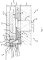
- Fig. 1 shows a partial sectional view of a building wall 210 of a building 300 with a ventilation system 1000, having a ventilation duct module 100 according to the invention.
- the building wall 210 has an outer wall layer 220, which in the present case is designed as a clinker brick wall 222.
- the wall outer layer 220 can also be formed within the framework of a standard thermal insulation composite system or a similar building wall in a different shape that deviates from a clinker brick wall 222.
- the wall outer layer 220 terminates with an outer side 310 of the building 300.
- an air layer 226 can be arranged between the wall outer layer 220 and the insulating layer 230.
- the air layer 226 can have an air layer width 228 of up to 40 mm.
- the insulating layer 230 is in turn adjoined by an inner wall layer 240 in the direction of an inner side 320 of the building 300.
- a ventilation device 200 and a duct 142 connected to it are arranged in a wall duct 312 which extends through the inner wall layer 240 and partially through the insulation layer 230.
- a soffit duct 140 adjoins the duct 142 in an air-conducting manner, which extends in the insulation layer 230 parallel to it along the wall outer layer 220 in the direction of a soffit 212 up to a ventilation duct module 100.
- the ventilation duct module 100 is arranged within a soffit edge zone LRZ.
- the ventilation duct module 100 has a duct connection 120 located in the area of the insulating layer 230 and a soffit connection 110 located in the area of the outer wall layer 220.
- the ventilation duct module 100 can thus a ventilation guidance direction LFR can be offset from the insulation layer 230 into the wall outer layer 120.
- the soffit duct 140 is connected in an air-conducting manner to a module body 130 of the ventilation duct module 100 via the duct connection 120.
- the soffit connection 110 of the ventilation duct module 100 is arranged on a soffit side 137 of the ventilation duct module 100, which is directed in the direction of a soffit surface 214 of the soffit 212.
- an air flow can be guided into or out of a reveal interior 216 enclosed by the reveal 212 in accordance with the ventilation guidance direction LFR.
- the module body 130 extends in a direction perpendicular to the building wall 210 from the inside to the outside as far as an outer wall zone WAG, whereby the outer wall layer 220 between the boundary of the outer wall zone WAG and the outer side 310 is not impaired, in particular does not have to be left out.
- the soffit edge zone LRZ extends from the soffit surface 214 parallel from this up to a zone spacing ZA into the outer layer.
- the soffit edge zone LRZ can extend into the soffit interior 216.
- a screen 338 through which a flow can flow is arranged on the soffit connection 110.
- a roller shutter rail 334 is arranged, and again in the same direction next to it a window 332.
- FIG. 2 A further development of a ventilation duct module 100 ′ is shown in a top view with a horizontal sectional plane, which has a connection extension 112.
- the connection extension 112 connects to the reveal connection 110 on the reveal side 137.
- the soffit connection 110 can be lengthened via the connection extension 112 so that it extends further in the direction of the soffit surface 214 and / or into the soffit edge zone LRZ and / or into the soffit interior 216.
- the connection extension 112 has a connection length 118.
- the connection extension 112 has an outer side wall 114 with an outer wall thickness WSA and an inner side wall 116 with an inner wall thickness WSI.
- the ventilation duct module 100 has a flow duct 128 which is arranged obliquely in the module body 130, namely at a duct angle WK to the reveal side 137 in order to move the ventilation guidance direction LFR from an insulating layer to an outer wall layer.
- the flow channel 128 has a channel cross section AKQ.
- the module body can have a bevel 132 — shown here with dashed lines. The bevel 132 can run parallel to the flow channel 128 and / or to the air flow direction LFR. In the case of a non-straight course of the flow channel, the channel angle is formed in particular from the mean value of the channel angles of all sections of the flow channel.
- the ventilation duct module 100 ' is shown in the installed state in a building wall 210 in a sectional view.
- the ventilation duct module 100 ′ is connected to a soffit duct 140 via the duct connection 120. Only shortly before reaching the reveal 212, in a reveal edge zone LRZ, the ventilation guidance direction LFR is shifted from the insulation layer 230 into the wall outer layer 220, and is guided via the reveal connection 110 and the connection extension 112 to the reveal surface 214.
- the ventilation duct module 100 ′ has a module depth 104 of approximately half a clinker brick length
- the connection extension 112 has a connection length 118 likewise of approximately half a clinker brick length.
- the connection extension 112 is arranged directly abutting with a window 332.
- Fig. 4 shows a perspective illustration of a ventilation duct module 100 ".
- the module body 130 of the ventilation duct module 100" has a cuboid shape 138 and in particular has an approximately right-angled outer shape.
- a connection extension 112 is connected to the ventilation duct module 100 ′′, in particular to the module body 130, at the soffit connection 110, which in the present case has three struts 160 arranged at a vertical distance over the channel cross section AKQ
- the ventilation duct module 100 ′′ has a module height 102.
- the ventilation duct module can be formed from plastic 180, sheet metal 182 or wood fibers 184, with a combination as well this or other materials is possible.
- the ventilation duct module 100 ′′ is designed symmetrically with respect to a mirror plane SPE, the mirror plane SPE being arranged horizontally at half of the module height 102.
- the ventilation duct module 100 ′′ has a module depth 104 which is advantageously designed to be relatively small, in particular half a clinker width, for example 110 mm.
- the ventilation duct module 100 ′′ has a module width 106.
- the module width 106 is composed of an inner area width 156 of a module inner area 152 adjoining the module inner side 135, which is in particular equal to the width of the duct connection 120, and a module core width 107.
- the inner area width 156 is in particular less than or equal to 70 mm and can advantageously be adapted to the width of the soffit channel and / or the channel connection 120.
- the module core width 107 can in particular be adapted to the offset to be bridged in the ventilation guidance direction and can in particular be 126 mm.
- a module outer area 150 adjoining the module outer side 134 and having an outer area width 154 is arranged within the module core width 107.
- the reveal connection 110 is arranged within the module outer area 150 on the reveal side 137 of the ventilation
- a ventilation duct module 100 '" is shown with a stabilization plate 170.
- the stabilization plate 170 is designed as an angle plate and is arranged above the ventilation duct module 100""in such a way that the horizontal part of the stabilization plate 170 is in a mortar layer 224 as a clinker wall 222 formed outer wall layer 220.
- forces from the outer wall layer can advantageously be absorbed and / or distributed and / or a mechanical strengthening of the ventilation duct module 100 ′ ′′ can be achieved.
- the stabilizing plate 170 is advantageously offset from the reveal surface 214 inward into the wall outer layer 220 and / or covered by a panel 338 so that it is not visible from the outside.
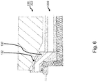
- a further development of a ventilation duct module 100 ′′ ′′ is shown in the installed state, with a module body 130 ′ having a bevel 132 having.
- the outer wall layer 220 in particular clinker bricks of a clinker wall 222, also only need to be beveled, which means that less material has to be removed from the outer wall layer, in particular in contrast to a right-angled notching of the clinker wall. In this way, the wall outer layer is advantageously even less structurally weakened.
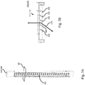
- FIG. 7A a further development of a diaphragm 338 in the form of a deflecting diaphragm 340 is shown.
- the deflection panel 340 has a number of deflection lamellas 342 which are designed to deflect the air flow emerging from a soffit connection 110 and / or a connection extension 112, in particular to deflect it away from the building.
- the exiting air flow can be deflected away from a window built into the reveal.
- Such a deflection advantageously prevents an area of the building wall and / or the reveal and / or a component built into the reveal, such as a window 332 or door, from being heated and / or humidified by the exiting air flow.
- the deflection panel 340 is designed to be connected to a jamb connection 110 and / or to a connection extension 112.
- Figure 7B shows a cross-sectional view of the deflection aperture 340 in a sectional plane SE.
- a number of five deflecting lamellas 342 are visible, which are arranged next to one another and, due to their curved cross section, are designed to change the air flow direction LFR of an air flow emerging from a ventilation duct module 100, in particular to direct the air flow away from the building.
- FIGS. 8A, 8B and 8C show a further development of a ventilation duct module 100 ′′ ′′ with a duct connection section 122 which adjoins the duct connection 120.
- the duct connection section 122 which, in particular after the installation of the ventilation duct module 100 ′′ ′′, is arranged within an insulation layer 230 (not shown), in the present case has four insulation holder receptacles 127, two of which are visible.
- An insulation holder receptacle 127 is designed to receive an insulation holder 124.
- the essentially shaft-shaped Insulation holder 124 has a round, disc-shaped insulation holder head 124.1.
- the insulation holder receptacle 127 is designed in such a way that, in the assembled state of the insulation holder 124, it can receive both the insulation holder head 124.1 and an insulation plug 126 flush, as shown in FIG Figure 8A in the insulation holder receptacle 127 below, as well as in Figure 8C is shown.
- An insulation plug can be formed from Styrofoam or similar insulation material, in particular from the same material as an insulation material 144 in the insulation layer 230 or from a material that is also used in the duct connection section 122.
- Figure 8B the ventilation duct module 100 "" is shown in a sectional view in the pre-assembly state.
- An insulation holder 124 and the duct connection section 122 with a first insulation holder receptacle 127A, which faces the insulation holder 124, and an opposite, second insulation holder receptacle 127B, which faces an insulation layer 230 (not shown here) are visible.
- an intermediate disk 126.1 is also arranged between the duct connection section 122 and the insulation plug 126, which is used in particular to better fix the insulation holder 124 in the assembled state.
- the intermediate disk 126.1 can in particular be formed from a harder plastic.
- Figure 8C the insulation holder is shown in the assembled state.
- the shaft of the insulation holder 124 penetrates the duct connection section 122, the intermediate disk 126.1 and the insulation plug 126 facing the insulation layer 230 and extends further into the insulation layer 230, in particular into an insulation material 144 not shown here.
- the ventilation duct module 100 ′′ ′′ can be fastened to an insulation layer 230, in particular to an insulation material 144, by one or more insulation holders 124.
- An insulation holder receptacle 127 has the advantage that the inclusion of an insulation plug 126 can reduce and / or avoid cold or heat bridges.
- One or more insulation holder receptacles 127 can be arranged in the duct connection section in such a way that they do not intersect the air-guiding part, that is to say a flow duct 128, so that insulation holder 124 does not come into direct contact with the guided air flow.
- one or more insulation holder receptacles 127 can be arranged in an upper and / or lower region of the duct connection section 122.
Landscapes
- Engineering & Computer Science (AREA)
- Chemical & Material Sciences (AREA)
- Combustion & Propulsion (AREA)
- Mechanical Engineering (AREA)
- General Engineering & Computer Science (AREA)
- Civil Engineering (AREA)
- Building Environments (AREA)
Abstract
Description
- Die Erfindung betrifft in einem ersten Aspekt ein Lüftungskanalmodul gemäß dem Oberbegriff des Anspruchs 1. Die Erfindung betrifft in einem zweiten Aspekt ein Lüftungssystem gemäß dem Anspruch 18. Die Erfindung betrifft in einem dritten Aspekt eine Gebäudewand gemäß dem Anspruch 19.
- Lüftungssysteme für die Belüftung von Gebäuden sind bekannt. Derartige Lüftungssysteme können Luft ab- und/oder zuführen. Bei der Luftführung muss eine Verbindung zwischen einem Wohnraum auf einer Innenseite einer Gebäudewand und einem Außenbereich auf einer Außenseite einer Gebäudewand gewährleistet werden. Hierfür wird eine Wanddurchführung durch die Gebäudewand mit einer Bohrung oder dergleichen Ausschnitt realisiert. Innerhalb der Wanddurchführung wird ein Kanal, insbesondere ein Durchführungskanal, und/oder ein Lüftungsgerät integriert. An der Innen- und Außenseite der Wand werden aus verschiedenen Gründen Abschlüsse (z.B. Wetterschutzhauben oder Design-Innenverschlüsse) verbaut. Die Abschlüsse für den Außenbereich werden oft sichtbar an der Fassade des Gebäudes angebracht. Diese Sichtbarkeit ist häufig nicht erwünscht.
- Aus diesem Grund werden Luftführungskanäle genutzt, die die Luft derart führen, dass ein Abschluss nicht auf der Fassade angeordnet ist, sondern in der seitlichen Laibung eines Wandausschnitts. Derartige Laibungskanäle schützen die optische Wahrnehmung der Fassade. Die Laibungskanäle werden im Wandaufbau integriert. Oft werden sie dort in die Wärmedämmung der Wand integriert.
- Bei Wandaufbauten mit einer Wandaußenschicht, insbesondere Klinker, mit Luftschicht oder ohne Luftschicht, werden die Fensterrahmen oft auf Stoß mit dem Klinker verbaut. Soll hier ein Laibungskanal verbaut werden, muss dieser innerhalb der Wandaußenschicht, insbesondere innerhalb des Klinkers, integriert werden. Die Wandaußenschicht, insbesondere die Klinkersteine, müssen dafür im Bereich des Laibungskanals verjüngt werden. Oftmals ist ein Einbau aufgrund der Geometrie des Laibungskanals erst gar nicht möglich.
- Eine derartige Verjüngung schwächt die Wandaußenschicht, insbesondere die Klinkerwand, vor allem strukturell. Witterungen, wie Windlasten und Schauer können Schäden an der Wandaußenschicht, insbesondere an der Klinkerwand, verursachen. Eine Verjüngung der Wandaußenschicht, insbesondere der Klinkersteine gilt es daher zu vermeiden.
- Wünschenswert ist es daher, ein Lüftungskanalmodul und ein Lüftungssystem bereitzustellen, welches sowohl optisch/ästhetischen Anforderungen genügt, als auch eine strukturelle Schwächung einer Wandaußenschicht, insbesondere einer Klinkerwand, eines Gebäudes, verringert.
- An dieser Stelle setzt die Erfindung an, deren Aufgabe es ist, ein verbessertes Lüftungskanalmodul und Lüftungssystem bereitzustellen, welches die im Stand der Technik vorherrschenden Probleme zumindest teilweise behebt. Insbesondere soll eine Leitung von Luft durch die Gebäudewand ermöglicht werden, welche sowohl optisch/ästhetischen Anforderungen genügt, als auch eine strukturelle Schwächung einer Wandaußenschicht, insbesondere einer Klinkerwand, eines Gebäudes, verringert.
- Die Aufgabe wird durch die Erfindung mit einem Lüftungskanalmodul des Anspruchs 1 gelöst. Die Erfindung geht aus von einem Lüftungskanalmodul für einen Laibungskanal, zum Einbau in eine Gebäudewand mit einer Laibung, aufweisend einen Strömungskanal, der einen Laibungsanschluss und einen Kanalanschluss in einer Luftführungsrichtung luftführend miteinander verbindet,
- Erfindungsgemäß ist bei dem Lüftungskanalmodul vorgesehen, dass
- der Laibungsanschluss auf einer Laibungsseite, die der Laibung zugewandt ist, innerhalb eines Modulaußenbereichs angeordnet ist, der an eine Modulaußenseite angrenzt, die einer Außenseite der Gebäudewand zugewandt ist, wobei
- das Lüftungskanalmodul zwischen dem Laibungsanschluss und dem Kanalanschluss wenigstens einen Bereich aufweist, in der die Luftführungsrichtung normal zur Gebäudewand versetzt wird.
- Indem der Laibungsanschluss auf der Laibungsseite innerhalb des Modulaußenbereichs angeordnet ist, und im Lüftungskanalmodul die Luftführungsrichtung normal zur Gebäudewand versetzt wird, wird eine geringe Modultiefe des Lüftungskanalmoduls erreicht. Durch eine geringe Modultiefe wird vorteilhaft eine Integration des Laibungskanals in die Gebäudewand ermöglicht, die nur eine relativ geringe Schwächung der Wandaußenschicht, insbesondere der Klinkerwand, verursacht. Insbesondere ist die Wandaußenschicht eine Klinkerwand.
- Ein Versetzen der Luftführungsrichtung normal zur Gebäudewand bedeutet, dass durch die Ausbildung und Anordnung des Strömungskanals der durch das Lüftungskanalmodul geführte Luftstrom zwischen zwei, insbesondere zur Gebäudewand parallelen, Ebenen versetzt wird, nämlich von einer Ebene, in der der Kanalanschluss liegt, zu einer Ebene, in der der Laibungsanschluss liegt. Die Luftführungsrichtung muss dabei nicht senkrecht zur Gebäudewand verlaufen. Um die Luftführungsrichtung normal zur Gebäudewand zu versetzen, ist der Strömungskanal parallel zur Laibungsseite oder in ein einem Kanalwinkel zur Laibungsseite angeordnet, der bevorzugt kleiner oder gleich 45° ist, besonders bevorzugt kleiner oder gleich 40° ist. Die Modultiefe erstreckt sich senkrecht zur Laibungsseite zwischen der Laibungsseite und einer gegenüberliegenden Modulrückseite.
- Je geringer die Modultiefe, desto größer ist der vorteilhafte Effekt der geringeren strukturellen Schwächung der Wandaußenschicht, insbesondere der Klinkerwand. Insbesondere ist die Wandaußenschicht eine Klinkerwand.
- Die Lüftungsführungsrichtung beschreibt die Strömung der durch das Lüftungskanalmodul strömenden Luft und liegt in der Mitte des Kanalquerschnitts.
- Das Klinkerformat, nämlich die Klinkerlänge, die Klinkerbreite, und die Klinkerhöhe ist insbesondere auf das Normalformat (NF) bezogen, in der die mit Klinkerlänge 240 mm, die Klinkerbreite 115 mm und die Klinkerhöhe 71 mm beträgt. Die Stärke der Mörtellage und somit der Abstand zwischen zwei Klinkersteinen beträgt insbesondere 10 mm. Gleichwohl sind im Rahmen der Erfindung andere Klinkerformate und/oder Mörtellagen gemäß DIN 1053 und/oder DIN 105 und/oder EN 771 möglich. Eine Klinkerhöhe schließt insbesondere eine Mörtellage ein.
- Vorteilhafte Weiterbildungen der Erfindung sind den Unteransprüchen zu entnehmen und geben im Einzelnen vorteilhafte Möglichkeiten an, das oben erläuterte Konzept im Rahmen der Aufgabenstellung sowie hinsichtlich weiterer Vorteile zu realisieren.
- Insbesondere ist vorgesehen, dass,
- der Kanalanschluss innerhalb eines Modulinnenbereichs angeordnet ist, der an eine Modulinnenseite angrenzt, die der Modulaußenseite gegenüberliegt, wobei
- der Kanalanschluss auf einer der Laibungsseite gegenüberliegenden Modulrückseite oder auf der Modulinnenseite angeordnet ist.
- Vorteilhaft ist vorgesehen, dass das Lüftungskanalmodul eine Modultiefe aufweist, die kleiner oder gleich 120 mm, besonders bevorzugt kleiner oder gleich 110 mm ist, wobei sich die Modultiefe senkrecht zur Laibungsseite zwischen der Laibungsseite und einer gegenüberliegenden Modulrückseite erstreckt.
- Eine derartige Weiterbildung berücksichtigt den Umstand, dass der Abschluss einer Klinkerwand vor der Laibung in der Regel aus vollen Klinkersteinen und in ihrer Klinkerlänge halbierten Klinkersteinen abwechselnd schichtweise gebildet wird. Eine Breite von 120 mm beträgt dabei in der Regel eine halbe Klinkerlänge, das heißt eine halbe Länge eines Klinkersteins. In einer Weiterbildung, in der die Modultiefe eine halbe Klinkerlänge oder weniger beträgt, müssen lediglich die vollen Klinkersteine verjüngt und/oder ausgeklinkt werden, und die halben Klinkersteine können vollständig entlang ihrer Längsachse auf eine halbe Klinkerbreite halbiert werden, wodurch der Arbeitsaufwand vorteilhaft reduziert wird.
- Das Lüftungskanalmodul weist insbesondere eine Modultiefe auf, welche relativ gering ausgebildet ist, insbesondere eine halbe Klinkerbreite, beispielsweise kleiner oder gleich 110 mm. Das Lüftungskanalmodul weist insbesondere eine Modulbreite auf, die sich aus einer Kanalanschlussbreite, welche die Breite des Kanalanschlusses beschreibt, und einer Modulkernbreite zusammensetzt. Die Kanalanschlussbreite ist insbesondere kleiner oder gleich 70 mm und kann vorteilhaft an die Breite des Laibungskanals angepasst werden. Die Modulkernbreite kann insbesondere an den zu überbrückenden Versatz der Lüftungsführungsrichtung angepasst werden und kann insbesondere 106 mm betragen.
- Vorteilhaft ist vorgesehen, dass eine Außenbereichsbreite des Modulaußenbereichs die Hälfte, bevorzugt ein Drittel, einer Modulbreite beträgt, wobei sich die Modulbreite parallel zur Laibungsseite zwischen der Modulaußenseite und der Modulinnenseite erstreckt. Je geringer die Außenbereichsbreite ist, desto näher ist der Laibungsanschluss an der Modulaußenseite angeordnet, wodurch eine weitere Schwächung der Wandaußenschicht vorteilhaft vermieden wird.
- Insbesondere ist vorgesehen, dass eine Innenbereichsbreite des Modulinnenbereichs die Hälfte, bevorzugt ein Drittel, einer Modulbreite beträgt.
- Vorteilhaft ist vorgesehen, dass der Strömungskanal in einem Kanalwinkel zur Laibungsseite verläuft, der kleiner oder gleich 40° ist. Bevorzugt ist der Kanalwinkel kleiner oder gleich 20°, besonders bevorzugt ist der Kanalwinkel kleiner oder gleich 10°. Je geringer der Kanalwinkel ist, desto geringer kann vorteilhaft - bei einem vergleichbaren Versatz der Luftführungsrichtung - die Modultiefe ausfallen.
- Vorteilhaft ist vorgesehen, dass der Strömungskanal einen vertikal länglichen Kanalquerschnitt (AKQ) aufweist, insbesondere ein Höhe-zu-Breite-Verhältnis von mindestens 8 zu 1. Durch eine geringe seitliche Ausprägung eines derartigen vertikal länglichen Kanalquerschnitts ist dieser besonders geeignet für eine Integration in eine - ebenfalls vertikal länglich ausgebildete - Laibungsoberfläche. Durch die entsprechend größere Höhe wird trotz der geringen Breite des Querschnitts ein Strömungsquerschnitt erreicht, der für einen benötigten Luftaustausch erforderlich ist.
- Vorteilhaft ist vorgesehen, dass der Laibungsanschluss eine sich normal zur Laibungsseite und/oder normal zur Laibungsoberfläche erstreckende Anschlussverlängerung aufweist. Insbesondere weist die Anschlussverlängerung eine Anschlusslänge auf, die kleiner oder gleich 120 mm ist. Insbesondere ist der Laibungsanschluss und/oder die Anschlussverlängerung ausgebildet, eine Blende oder dergleichen Abschlusselement aufzunehmen. Insbesondere weist der Laibungsanschluss und/oder die Anschlussverlängerung eine Blende oder dergleichen Abschlusselement auf. Durch eine Anschlussverlängerung wird insbesondere das Problem gelöst, dass im Stand der Technik Abschlüsse von Laibungskanälen oft nicht für Klinkerwände geeignet ist, weil beispielsweise ein Fensterrahmen und ein Abschluss eines Laibungskanals oft keinen gemeinsamen Bauraum im Klinker finden.
- Vorteilhaft ist vorgesehen, dass die Anschlussverlängerung eine zur Außenseite der Gebäudewand gerichtete, äußere Seitenwand mit einer äußeren Wandstärke und eine gegenüberliegende innere Seitenwand mit einer inneren Wandstärke aufweist, wobei die innere Wandstärke größer ist als die äußere Wandstärke. Indem die innere Wandstärke größer ist, beispielsweise 8 bis 25 mm beträgt, kann eine Anbindung mit einem Fensterrahmen und/oder einer Rollladenschiene verbessert werden, insbesondere, weil ein ansonsten bestehender Zwischenraum durch die Wandstärke ausgefüllt wird. Vorteilhaft ist vorgesehen, dass die innere Seitenwand der Anschlussverlängerung und/oder der Laibungsanschluss angeordnet ist zum Anliegen an ein in der Laibung angeordnetes Fenster oder an eine in der Laibung angeordnete Rollladenschiene, wobei das Anliegen direkt oder über eine Dichtmittelfuge erfolgt.
- Insbesondere ist vorgesehen, dass das Lüftungskanalmodul und/oder die Anschlussverlängerung gebildet ist aus mindestens einem der folgenden Materialien: Kunststoff, Blech, Holzfasern. Insbesondere ist das Lüftungskanalmodul oder der Modulkorpus oder die Anschlussverlängerung aus einem Material gebildet, welches die Brandklasse der Dämmung, d. h. des in der Dämmschicht verwendeten Materials, erfüllt. Insbesondere ist das Lüftungskanalmodul oder der Modulkorpus oder die Anschlussverlängerung aus einem expandierten oder extrudierten Kunststoff hergestellt.
- Vorteilhaft ist mindestens eine Verstrebung vorgesehen, die innerhalb des Strömungskanals und/oder der Anschlussverlängerung angeordnet ist. Mittels einer möglichst strömungsgünstig ausgebildeten und/oder angeordneten Verstrebung kann die mechanische Stabilität des Lüftungskanalmoduls und/oder Anschlussverlängerung verbessert werden.
- Vorteilhaft ist mindestens ein Stabilisierungsblech vorgesehen zur Aufnahme in eine Mörtellage einer Wandaußenschicht der Gebäudewand, wobei
- die Wandaußenschicht eine zur Außenseite der Gebäudewand gerichtete Schicht der Gebäudewand ist, und
- das Stabilisierungsblech an dem Lüftungskanalmodul befestigt ist oder an dem Lüftungskanalmodul anliegt, insbesondere aufliegt.
- Insbesondere ist vorgesehen, dass das Lüftungskanalmodul symmetrisch zu einer horizontal in der Mitte des Lüftungskanalmoduls liegenden Spiegelebene (SPE) ausgebildet ist. Durch eine derartige symmetrische Ausbildung kann vorteilhaft eine beidseitige Montage, d. h. links und rechts bzw. oben und unten in einer Laibung, ermöglicht werden, ohne das Lüftungskanalmodul in seiner Bauart variieren zu müssen.
- Insbesondere ist vorgesehen, dass das Lüftungskanalmodul, insbesondere ein Modulkorpus des Lüftungskanalmoduls, eine Quaderform aufweist. Durch eine Quaderform und die damit verbundene rechtwinklige Ausbildung des Lüftungskanalmoduls kann dieses vorteilhaft in einer ebenfalls rechtwinkligen Aussparung in der Wandaußenschicht untergebracht werden. Insbesondere Klinkersteine müssen dafür lediglich mit geraden Schnitten rechtwinklig zum Klinkerstein bearbeitet werden.
- In einer vorteilhaften Weiterbildung ist vorgesehen, dass der Modulkorpus eine Anschrägung aufweist, die zwischen der Modulaußenseite und einer der Laibungsseite gegenüberliegenden Modulrückseite angeordnet ist. Insbesondere verläuft die Anschrägung parallel zur Luftführungsrichtung und/oder zum Strömungskanal. Durch eine Anschrägung kann das Volumen des Modulkorpus vorteilhaft verringert werden, wodurch eine Aussparung in der Wandaußenschicht kleiner ausfallen kann, wodurch wiederum die Wandaußenschicht, insbesondere die Klinkerwand, vorteilhaft weniger strukturell geschwächt wird.
- Insbesondere ist vorgesehen, dass das Lüftungskanalmodul eine Blende, insbesondere eine Umlenkblende mit mindestens einer Umlenklamelle, aufweist.
- Insbesondere ist vorgesehen, dass das Lüftungskanalmodul eine Kanalanschlusssektion mit mindestens einer Dämmhalteraufnahme aufweist, wobei die mindestens eine Dämmhalteraufnahme zur Aufnahme eines Dämmstopfens ausgebildet ist. Die Dämmhalteraufnahme weist insbesondere eine zylindrische Form auf.
- Insbesondere ist vorgesehen, dass das Lüftungskanalmodul eine Modulhöhe aufweist, die ein Vielfaches einer Klinkerhöhe beträgt und/oder einer Summe von einer Klinkerhöhe und einer Mörtellage beträgt. Insbesondere beträgt die Modulhöhe ein Vielfaches von 71 mm oder 81 mm. Insbesondere beträgt die Modulhöhe zwischen 426 mm oder 486 mm. Durch eine Modulhöhe, die ein Vielfaches der Klinkerhöhe und/oder der Summe von Klinkerhöhe und Mörtellage beträgt, kann vorteilhaft ein Einbau in einer Klinkerwand ermöglicht werden, ohne die Höhe einzelner Klinkersteine anpassen zu müssen.
- Insbesondere ist vorgesehen, dass das Lüftungskanalmodul oder der Modulkorpus derart ausgebildet und angeordnet ist, dass eine innerhalb der Wandaußenschicht parallel zur Außenseite angeordnete Wandaußenzone in Richtung der Außenseite des Gebäudes nicht überschritten wird, wobei die Wandaußenzone mindestens eine halbe Klinkerbreite von der Außenseite nach Innen beabstandet ist. In einer derartigen Weiterbildung wird vorteilhaft erreicht, dass die Wandaußenschicht, insbesondere die Klinkerwand, im Bereich der Laibungsrandzone mindestens eine halbe Klinkerbreite aufweist und somit eine mechanische Mindeststabilität. Insbesondere ist die Wandaußenzone mindestens 55 mm, bevorzugt 57,5 mm, von der Außenseite der Wandaußenschicht nach innen beanstandet.
- Die Erfindung führt in einem zweiten Aspekt auch auf ein Lüftungssystem, aufweisend
- ein Lüftungskanalmodul gemäß dem ersten Aspekt der Erfindung zum Einbau in eine Gebäudewand,
- ein Lüftungsgerät, und
- einen Laibungskanal, der das Lüftungskanalmodul und das Lüftungsgerät luftführend verbindet und insbesondere in einer Dämmschicht angeordnet ist, wobei die Dämmschicht zwischen einer Wandaußenschicht und einer Wandinnenschicht liegt. Bei dem Lüftungssystem werden die Vorteile des Lüftungskanalmoduls gemäß dem ersten Aspekt der Erfindung vorteilhaft genutzt.
- Die Erfindung führt in einem dritten Aspekt auch auf eine Gebäudewand mit einer Laibung aufweisend eine Wandaußenschicht, insbesondere Klinkerwand, und eine Dämmschicht mit einem Lüftungskanalmodul gemäß dem ersten Aspekt der Erfindung und/oder einem Lüftungssystem gemäß dem zweiten Aspekt der Erfindung, wobei insbesondere
- das Lüftungskanalmodul innerhalb einer Laibungsrandzone angeordnet ist, wobei die Laibungsrandzone parallel zur Laibungsoberfläche um einen Zonenabstand in die Gebäudewand versetzt ist.
- Die Laibungsrandzone ist so zu verstehen, dass sich der Modulkorpus in eine von der Laibungsoberfläche in die Gebäudewand hinein gerichtete Richtung die Laibungsrandzone nicht überschreitet, in Gegenrichtung jedoch in einen Laibungsinnenraum hineinreichen kann. Die Laibungsrandzone umfasst somit auch einen Laibungsinnenraum, das heißt ein von der Laibung umschlossenes Volumen. Vorteilhaft ist vorgesehen, dass das Lüftungskanalmodul vollständig innerhalb der Laibungsrandzone untergebracht ist.
- In einer Weiterbildung weist die Gebäudewand eine Wandinnenschicht auf. Insbesondere ist die Gebäudewand eine Gebäudeaußenwand.
- Ausführungsformen der Erfindung werden nun nachfolgend anhand der Zeichnung beschrieben. Diese soll die Ausführungsformen nicht notwendigerweise maßstäblich darstellen, vielmehr ist die Zeichnung, wo zur Erläuterung dienlich, in schematisierter und/oder leicht verzerrter Form ausgeführt. Im Hinblick auf Ergänzungen der aus der Zeichnung unmittelbar erkennbaren Lehren wird auf den einschlägigen Stand der Technik verwiesen. Dabei ist zu berücksichtigen, dass vielfältige Modifikationen und Änderungen betreffend die Form und das Detail einer Ausführungsform vorgenommen werden können, ohne von der allgemeinen Idee der Erfindung abzuweichen. Die in der Beschreibung, in der Zeichnung sowie in den Ansprüchen offenbarten Merkmale der Erfindung können sowohl einzeln als auch in beliebiger Kombination für die Weiterbildung der Erfindung wesentlich sein. Zudem fallen in den Rahmen der Erfindung alle Kombinationen aus zumindest zwei der in der Beschreibung, der Zeichnung und/oder den Ansprüchen offenbarten Merkmale. Die allgemeine Idee der Erfindung ist nicht beschränkt auf die exakte Form oder das Detail der im folgenden gezeigten und beschriebenen bevorzugten Ausführungsformen oder beschränkt auf einen Gegenstand, der eingeschränkt wäre im Vergleich zu dem in den Ansprüchen beanspruchten Gegenstand. Bei angegebenen Bemessungsbereichen sollen auch innerhalb der genannten Grenzen liegende Werte als Grenzwerte offenbart und beliebig einsetzbar und beanspruchbar sein. Der Einfachheit halber sind nachfolgend für identische oder ähnliche Teile oder Teile mit identischer oder ähnlicher Funktion gleiche Bezugszeichen verwendet.
- Weitere Vorteile, Merkmale und Einzelheiten der Erfindung ergeben sich aus der nachfolgenden Beschreibung der bevorzugten Ausführungsformen sowie anhand der Zeichnung; diese zeigt in:
- Fig. 1
- eine ausschnittsweise Schnittdarstellung einer Gebäudewand mit einem Lüftungssystem, aufweisend ein Lüftungskanalmodul gemäß der Erfindung,
- Fig. 2
- eine Schnittdarstellung einer Weiterbildung des Lüftungskanalmoduls,
- Fig. 3
- eine perspektivische Schnittdarstellung eines Lüftungskanalmoduls im eingebauten Zustand,
- Fig. 4
- eine Darstellung einer Weiterbildung eines Lüftungskanalmoduls,
- Fig. 5
- eine Darstellung einer Weiterbildung eines Lüftungskanalmoduls mit einem Stabilisierungsblech,
- Fig. 6
- eine Darstellung einer Weiterbildung eines Lüftungskanalmoduls mit einer Anschrägung.
-
Fig. 1 zeigt eine ausschnittsweise Schnittdarstellung einer Gebäudewand 210 eines Gebäudes 300 mit einem Lüftungssystem 1000, aufweisend ein Lüftungskanalmodul 100 gemäß der Erfindung. Die Gebäudewand 210 weist eine Wandaußenschicht 220 auf, welche vorliegend als Klinkerwand 222 ausgebildet ist. Die Wandaußenschicht 220 kann in Weiterbildungen auch im Rahmen eines Standard-Wärmedamm-Verbundsystems oder dergleichen Gebäudewand in einer anderen, von einer Klinkerwand 222 abweichenden Form gebildet sein. Die Wandaußenschicht 220 schließt mit einer Außenseite 310 des Gebäudes 300 ab. An der - der Außenseite 310 gegenüberliegenden - Seite der Wandaußenschicht 220 schließt sich eine Dämmschicht 230 an, in der insbesondere Dämmmaterial 144 angeordnet ist. In optionalen Weiterbildungen kann zwischen der Wandaußenschicht 220 und der Dämmschicht 230 eine Luftschicht 226 angeordnet sein. Die Luftschicht 226 kann eine Luftschichtbreite 228 von bis zu 40 mm aufweisen. An die Dämmschicht 230 schließt sich wiederum in Richtung einer Innenseite 320 des Gebäudes 300 eine Wandinnenschicht 240 an. - Ein Lüftungsgerät 200 und ein daran angeschlossener Durchführungskanal 142 sind in einer Wanddurchführung 312 angeordnet, die sich durch die Wandinnenschicht 240 und teilweise durch die Dämmschicht 230 erstreckt. An den Durchführungskanal 142 schließt sich luftführend ein Laibungskanal 140 an, welcher sich in der Dämmschicht 230 parallel zu dieser an der Wandaußenschicht 220 entlang in Richtung einer Laibung 212 bis zum ein Lüftungskanalmodul 100 erstreckt. Das Lüftungskanalmodul 100 ist innerhalb einer Laibungsrandzone LRZ angeordnet. Das Lüftungskanalmodul 100 weist einen im Bereich der Dämmschicht 230 liegenden Kanalanschluss 120, und einen im Bereich der Wandaußenschicht 220 liegenden Laibungsanschluss 110 auf. Durch das Lüftungskanalmodul 100 kann somit eine Lüftungsführungsrichtung LFR aus der Dämmschicht 230 in die Wandaußenschicht 120 versetzt werden. Über den Kanalanschluss 120 ist der Laibungskanal 140 mit einem Modulkorpus 130 des Lüftungskanalmoduls 100 luftführend verbunden. Der Laibungsanschluss 110 des Lüftungskanalmoduls 100 ist an einer Laibungsseite 137 des Lüftungskanalmoduls 100 angeordnet, die in Richtung einer Laibungsoberfläche 214 der Laibung 212 gerichtet ist. Durch die Anordnung des Laibungsanschlusses 110 in der Wandaußenschicht 220 kann ein Luftstrom gemäß der Lüftungsführungsrichtung LFR in einen von der Laibung 212 umschlossenen Laibungsinnenraum 216 oder aus diesem herausgeführt werden. Der Modulkorpus 130 erstreckt sich in einer Richtung senkrecht zur Gebäudewand 210 von innen nach außen bis zu einer Wandaußenzone WAG, wodurch zwischen der Grenze der Wandaußenzone WAG und der Außenseite 310 die Wandaußenschicht 220 nicht beeinträchtigt wird, insbesondere nicht ausgespart werden muss. Die Laibungsrandzone LRZ erstreckt sich von der Laibungsoberfläche 214 parallel von dieser bis zu einem Zonenabstand ZA in die Außenschicht hinein. Die Laibungsrandzone LRZ kann sich in den Laibungsinnenraum 216 erstrecken.
- Auf dem Laibungsanschluss 110 ist eine durchströmbare Blende 338 angeordnet. In der Laibung 212 ist neben dem Laibungsanschluss 110 in Richtung Innenseite 320 eine Rollladenschiene 334 angeordnet, und wiederum in derselben Richtung daneben ein Fenster 332. Zwischen der Blende 338 bzw. dem Laibungsanschluss 110 und der Rollladenschiene 334 ist eine Dichmittelfuge 336 angeordnet. Durch eine Dichtmittelfuge 336 kann das Lüftungskanalmodul vorteilhaft auf Stoß installiert werden und die Schlagregendichtigkeit erhöht werden.
- In
Fig. 2 ist eine Weiterbildung eines Lüftungskanalmoduls 100' in einer Draufsicht mit horizontaler Schnittebene gezeigt, welche eine Anschlussverlängerung 112 aufweist. Die Anschlussverlängerung 112 schließt sich auf der Laibungsseite 137 an den Laibungsanschluss 110 an. Über die Anschlussverlängerung 112 kann der Laibungsanschluss 110 verlängert werden, sodass er sich weiter in Richtung der Laibungsoberfläche 214 und/oder in die Laibungsrandzone LRZ und/oder in den Laibungsinnenraum 216 hinein erstreckt. Die Anschlussverlängerung 112 weist eine Anschlusslänge 118 auf. Die Anschlussverlängerung 112 weist eine äußere Seitenwand 114 mit einer äußeren Wandstärke WSA und eine innere Seitenwand 116 mit einer inneren Wandstärke WSI auf. Vorliegend ist die innere Wandstärke WSI größer als die äußere Wandstärke WSA. Das Lüftungskanalmodul 100 weist einen Strömungskanal 128 auf, der im Modulkorpus 130 schräg angeordnet ist, nämlich in einem Kanalwinkel WK zur Laibungsseite 137, um die Lüftungsführungsrichtung LFR aus einer Dämmschicht in eine Wandaußenschicht zu versetzen. Der Strömungskanal 128 weist einen Kanalquerschnitt AKQ auf. Optional kann der Modulkorpus eine - hier gestrichelt dargestellte - Anschrägung 132 aufweisen. Die Anschrägung 132 kann parallel zum Strömungskanal 128 und/oder zur Luftführungsrichtung LFR verlaufen. Bei einem nicht geraden Verlauf des Strömungskanals bildet sich der Kanalwinkel insbesondere aus dem Mittelwert der Kanalwinkel aller Abschnitte des Strömungskanals. - In
Fig. 3 ist das Lüftungskanalmodul 100' im eingebauten Zustand in einer Gebäudewand 210 in einer Schnittdarstellung gezeigt. Über den Kanalanschluss 120 ist das Lüftungskanalmodul 100' an einen Laibungskanal 140 angeschlossen. Erst kurz vor Erreichen der Laibung 212, in einer Laibungsrandzone LRZ, wird die Lüftungsführungsrichtung LFR aus der Dämmschicht 230 in die Wandaußenschicht 220 versetzt, und wird über den Laibungsanschluss 110 und die Anschlussverlängerung 112 zur Laibungsoberfläche 214 geführt. Vorliegend weist das Lüftungskanalmodul 100' eine Modultiefe 104 von näherungsweise einer halben Klinkerlänge, und die Anschlussverlängerung 112 eine Anschlusslänge 118 ebenfalls von näherungsweise einer halben Klinkerlänge. Die Anschlussverlängerung 112 ist vorliegend direkt auf Stoß anliegend mit einem Fenster 332 angeordnet. -
Fig. 4 zeigt eine perspektivische Darstellung eines Lüftungskanalmoduls 100". Der Modulkorpus 130 des Lüftungskanalmoduls 100" weist eine Quaderform 138 auf und weist insbesondere eine annähernd rechtwinklige Außenform auf. An das Lüftungskanalmodul 100", insbesondere an den Modulkorpus 130, ist am Laibungsanschluss 110 eine Anschlussverlängerung 112 angeschlossen, die vorliegend drei über den Kanalquerschnitt AKQ in vertikalem Abstand angeordnete Verstrebungen 160 aufweist. In Weiterbildungen ist es möglich, dass alternativ oder zusätzlich der Modulkorpus 130 Verstrebungen aufweist. Das Lüftungskanalmodul 100" weist eine Modulhöhe 102 auf. Das Lüftungskanalmodul kann aus Kunststoff 180, Blech 182 oder Holzfasern 184 gebildet sein, wobei auch eine Kombination dieser oder anderer Materialien möglich ist. Das Lüftungskanalmodul 100" ist symmetrisch bezüglich einer Spiegelebene SPE ausgebildet, wobei die Spiegelebene SPE horizontal auf der Hälfte der Modulhöhe 102 angeordnet ist. - Das Lüftungskanalmodul 100" weist eine Modultiefe 104 auf, welche vorteilhaft relativ gering ausgebildet ist, insbesondere eine halbe Klinkerbreite, beispielsweise 110 mm. Das Lüftungskanalmodul 100" weist eine Modulbreite 106 auf. Insbesondere setzt sich die Modulbreite 106 aus einer Innenbereichsbreite 156 eines an die Modulinnenseite 135 angrenzenden Modulinnenbereichs 152, welche insbesondere gleich der Breite des Kanalanschlusses 120 ist, und einer Modulkernbreite 107 zusammen. Die Innenbereichsbreite 156 ist insbesondere kleiner oder gleich 70 mm und kann vorteilhaft an die Breite des Laibungskanals und/oder des Kanalanschlusses 120 angepasst werden. Die Modulkernbreite 107 kann insbesondere an den zu überbrückenden Versatz der Lüftungsführungsrichtung angepasst werden und kann insbesondere 126 mm betragen. Innerhalb der Modulkernbreite 107 ist ein an die Modulaußenseite 134 angrenzender Modulaußenbereich 150 mit einer Außenbereichsbreite 154 angeordnet. Der Laibungsanschluss 110 ist innerhalb des Modulaußenbereichs 150 an der Laibungsseite 137 des Lüftungskanalmoduls 100" angeordnet.
- In
Fig. 5 ist eine Weiterbildung eines Lüftungskanalmoduls 100'" gezeigt mit einem Stabilisierungsblech 170. Vorliegend ist das Stabilisierungsblech 170 als Winkelblech ausgebildet und oberhalb des Lüftungskanalmoduls 100"" an diesem anliegend angeordnet derart, dass sich der horizontale Teil des Stabilisierungsblech 170 in eine Mörtellage 224 der als Klinkerwand 222 ausgebildeten Wandaußenschicht 220 erstreckt. Durch das Stabilisierungsblech 170 können vorteilhaft Kräfte aus der Wandaußenschicht aufgenommen und/oder verteilt werden und/oder eine mechanische Stärkung des Lüftungskanalmoduls 100'" erreicht werden. Vorteilhaft ist das Stabilisierungsblech 170 von der Laibungsoberfläche 214 nach innen in die Wandaußenschicht 220 versetzt und/oder von einer Blende 338 überdeckt, sodass es von außen nicht sichtbar ist. - In
Fig. 6 ist eine weitere Weiterbildung eines Lüftungskanalmoduls 100"" im installierten Zustand gezeigt, mit einem Modulkorpus 130', der eine Anschrägung 132 aufweist. Es wird deutlich, dass in einer derartigen Weiterbildung die Wandaußenschicht 220, insbesondere Klinkersteine einer Klinkerwand 222 ebenfalls lediglich angeschrägt werden brauchen, wodurch - insbesondere im Gegensatz zu einem rechtwinkligen Ausklinken der Klinkerwand - weniger Material aus der Wandaußenschicht entfernt werden muss. Auf diese Weise wird die Wandaußenschicht vorteilhaft noch weniger strukturell geschwächt. - In
Fig. 7A ist eine Weiterbildung einer Blende 338 in Form einer Umlenkblende 340 dargestellt. Die Umlenkblende 340 weist eine Anzahl von Umlenklamellen 342 auf, die ausgebildet sind, den aus einem Laibungsanschluss 110 und/oder einer Anschlussverlängerung 112 austretenden Luftstrom abzulenken, insbesondere vom Gebäude weg zu lenken. Insbesondere kann der austretende Luftstrom von einem in der Laibung verbauten Fenster weggelenkt werden. Durch ein derartiges Ablenken wird vorteilhaft vermieden, dass ein an die Blende angrenzender Bereich der Gebäudewand und/oder der Laibung und/oder eines in der Laibung verbauten Bauteils wie Fenster 332 oder Tür, durch den austretenden Luftstrom erwärmt und/oder befeuchtet wird. Somit werden durch eine Umlenkblende vorteilhaft langfristige optische Beeinträchtigungen und/oder Schäden, insbesondere durch Feuchtigkeit, vermieden. Die Umlenkblende 340 ist ausgebildet, an einen Laibungsanschluss 110 und/oder an eine Anschlussverlängerung 112 angeschlossen zu werden.Fig. 7B zeigt eine Querschnittsansicht der Umlenkblende 340 in einer Schnittebene SE. Vorliegend ist eine Anzahl von fünf Umlenklamellen 342 sichtbar, die nebeneinander angeordnet sind und durch ihren gekrümmten Querschnitt ausgebildet sind, die Luftführungsrichtung LFR eines aus einem Lüftungskanalmodul 100 austretenden Luftstroms zu verändern, insbesondere den Luftstrom vom Gebäude weg zu lenken. - Die
Figuren 8A, 8B und 8C zeigen eine weitere Weiterbildung eines Lüftungskanalmoduls 100"" mit einer Kanalanschlusssektion 122, die sich an den Kanalanschluss 120 anschließt. Die Kanalanschlusssektion 122, die insbesondere nach der Montage des Lüftungskanalmoduls 100"" innerhalb einer nicht dargestellten Dämmschicht 230 angeordnet ist, weist vorliegend vier Dämmhalteraufnahmen 127 auf, von denen zwei sichtbar sind. Eine Dämmhalteraufnahme 127 ist zur Aufnahme eines Dämmhalters 124 ausgebildet. Der im Wesentlichen schaftförmige Dämmhalter 124 weist einen runden, scheibenförmigen Dämmhalterkopf 124.1 auf. Die Dämmhalteraufnahme 127 ist derartig ausgebildet, dass sie im montierten Zustand des Dämmhalters 124 sowohl den Dämmhalterkopf 124.1, als auch einen Dämmstopfen 126 bündig aufnehmen kann, wie dies inFig. 8A in der untenliegenden Dämmhalteraufnahme 127, sowie inFig. 8C dargestellt ist. Ein Dämmstopfen kann aus Styropor oder dergleichen Dämmmaterial gebildet sein, insbesondere aus demselben Material wie ein Dämmmaterial 144 in der Dämmschicht 230 oder aus einem Material, das auch in der Kanalanschlusssektion 122 verwendet wird. InFig. 8B ist das Lüftungskanalmodul 100"" in einer Schnittansicht im Vormontagezustand dargestellt. Sichtbar ist ein Dämmhalter 124 sowie die Kanalanschlusssektion 122 mit einer ersten Dämmhalteraufnahme 127A, die zum Dämmhalter 124 gewandt ist, sowie einer gegenüberliegenden zweiten Dämmhalteraufnahme 127B, die einer hier nicht dargestellten Dämmschicht 230 zugewandt ist. In der zweiten Dämmhalteraufnahme 127B ist weiterhin, zwischen der Kanalanschlusssektion 122 und dem Dämmstopfen 126, eine Zwischenscheibe 126.1 angeordnet, die insbesondere der besseren Fixierung des Dämmhalters 124 im montierten Zustand dient. Die Zwischenscheibe 126.1 kann insbesondere aus einem härteren Kunststoff gebildet sein. InFig. 8C ist der Dämmhalter im montierten Zustand gezeigt. Der Schaft des Dämmhalters 124 durchdringt dabei die Kanalanschlusssektion 122, die Zwischenscheibe 126.1 und den zur Dämmschicht 230 gewandten Dämmstopfen 126 und reicht weiter in die Dämmschicht 230, insbesondere in ein hier nicht dargestelltes Dämmmaterial 144 hinein. Insbesondere kann das Lüftungskanalmodul 100"" durch einen oder mehrere Dämmhalter 124 an einer Dämmschicht 230, insbesondere an einem Dämmmaterial 144 befestigt werden. Eine Dämmhalteraufnahme 127 hat den Vorteil, dass durch die Aufnahme eines Dämmstopfens 126 Kälte- bzw. Wärmebrücken verringert und/oder vermieden werden können. Eine oder mehrere Dämmhalteraufnahmen 127 können derart in der Kanalanschlusssektion angeordnet sein, dass sie den luftführenden Teil, das heißt einen Strömungskanal 128 nicht schneiden, sodass der Dämmhalter 124 nicht in direkten Kontakt mit dem geführten Luftstrom kommt. Insbesondere können eine oder mehrere Dämmhalteraufnahmen 127 in einem oberen und/oder unteren Bereich der Kanalanschlusssektion 122 angeordnet sein. -
- 100, 100', 100", 100''', 100""
- Lüftungskanalmodul
- 102
- Modulhöhe
- 104
- Modultiefe
- 106
- Modulbreite
- 107
- Modulkernbreite
- 110
- Laibungsanschluss
- 112
- Anschlussverlängerung
- 114
- äußere Seitenwand der Anschlussverlängerung
- 116
- innere Seitenwand der Anschlussverlängerung
- 118
- Anschlusslänge
- 120
- Kanalanschluss
- 122
- Kanalanschlusssektion
- 124
- Dämmhalter
- 124.1
- Dämmhalterkopf
- 126
- Dämmstopfen
- 126.1
- Zwischenscheibe
- 127
- Dämmhalteraufnahme
- 127A, 127B
- erste, zweite Dämmhalteraufnahme
- 128
- Strömungskanal
- 130, 130'
- Modulkorpus
- 132
- Anschrägung
- 134
- Modulaußenseite
- 135
- Modulinnenseite
- 136
- Modulrückseite
- 137
- Laibungsseite
- 138
- Quaderform
- 140
- Laibungskanal
- 142
- Durchführungskanal
- 144
- Dämmmaterial
- 150
- Modulaußenbereich
- 152
- Modulinnenbereich
- 154
- Außenbereichsbreite
- 156
- Innenbereichsbreite
- 160
- Verstrebung
- 170
- Stabilisierungsblech
- 180
- Kunststoff
- 182
- Blech
- 184
- Holzfasern
- 200
- Lüftungsgerät
- 210
- Gebäudewand
- 212
- Laibung
- 214
- Laibungsoberfläche
- 216
- Laibungsinnenraum
- 220
- Wandaußenschicht
- 222
- Klinkerwand
- 224
- Mörtellage
- 226
- Luftschicht
- 228
- Luftschichtbreite
- 230
- Dämmschicht
- 240
- Wandinnenschicht
- 300
- Gebäude
- 310
- Außenseite des Gebäudes
- 312
- Wanddurchführung
- 320
- Innenseite des Gebäudes
- 332
- Fenster
- 334
- Rollladenschiene
- 336
- Dichtmittelfuge
- 338
- Blende
- 340
- Umlenkblende
- 342
- Umlenklamelle
- 1000
- Lüftungssystem
- AKQ
- Kanalquerschnitt
- KB
- Klinkerbreite
- KH
- Klinkerhöhe
- KL
- Klinkerlänge
- LFR
- Lüftungsführungsrichtung
- LRZ
- Laibungsrandzone
- SE
- Schnittebene
- SPE
- Spiegelebene
- WSA
- äußere Wandstärke
- WSI
- innere Wandstärke
- ZA
- Zonenabstand
Claims (19)
- Lüftungskanalmodul (100) für einen Laibungskanal (140), zum Einbau in eine Gebäudewand (210) mit einer Laibung (212), aufweisend einen Strömungskanal (128), der einen Laibungsanschluss (110) und einen Kanalanschluss (120) in einer Luftführungsrichtung (LFR) luftführend miteinander verbindet, dadurch gekennzeichnet, dass- der Laibungsanschluss (110) auf einer Laibungsseite (137), die der Laibung (212) zugewandt ist, innerhalb eines Modulaußenbereichs (150) angeordnet ist, der an eine Modulaußenseite (134) angrenzt, die einer Außenseite (310) der Gebäudewand (210) zugewandt ist, wobei- das Lüftungskanalmodul (100) zwischen dem Laibungsanschluss (110) und dem Kanalanschluss (120) wenigstens einen Versatzbereich (190) aufweist, in der die Luftführungsrichtung (LFR) normal zur Gebäudewand (210) versetzt wird.
- Lüftungskanalmodul (100) nach Anspruch 1, dadurch gekennzeichnet, dass- der Kanalanschluss (120) innerhalb eines Modulinnenbereichs (152) angeordnet ist, der an eine Modulinnenseite (135) angrenzt, die der Modulaußenseite (134) gegenüberliegt, wobei- der Kanalanschluss (120) auf einer der Laibungsseite (137) gegenüberliegenden Modulrückseite (136) oder auf der Modulinnenseite (135) angeordnet ist.
- Lüftungskanalmodul (100) nach Anspruch 1 oder 2, dadurch gekennzeichnet, dass das Lüftungskanalmodul (100) eine Modultiefe (104) aufweist, die kleiner oder gleich 120 mm, besonders bevorzugt kleiner oder gleich 110 mm ist, wobei sich die Modultiefe (104) senkrecht zur Laibungsseite (137) zwischen der Laibungsseite (137) und einer gegenüberliegenden Modulrückseite (136) erstreckt.
- Lüftungskanalmodul (100) nach einem der Ansprüche 1 bis 3, dadurch gekennzeichnet, dass eine Außenbereichsbreite (154) des Modulaußenbereichs (150) die Hälfte, bevorzugt ein Drittel, einer Modulbreite (106) beträgt, wobei sich die Modulbreite (106) parallel zur Laibungsseite (137) zwischen der Modulaußenseite (134) und der Modulinnenseite (135) erstreckt.
- Lüftungskanalmodul (100) nach einem der Ansprüche 1 bis 4, dadurch gekennzeichnet, dass eine Innenbereichsbreite (156) des Modulinnenbereichs (152) die Hälfte, bevorzugt ein Drittel, einer Modulbreite (106) beträgt.
- Lüftungskanalmodul (100) nach einem der Ansprüche 1 bis 5, dadurch gekennzeichnet, dass der Strömungskanal (128) in einem Kanalwinkel (WK) zur Laibungsseite (137) verläuft, der kleiner oder gleich 45° ist.
- Lüftungskanalmodul (100) nach einem der Ansprüche 1 bis 6, dadurch gekennzeichnet, dass der Strömungskanal (128) einen vertikal länglichen Kanalquerschnitt (AKQ) aufweist, insbesondere ein Höhe-zu-Breite-Verhältnis von mindestens 8 zu 1.
- Lüftungskanalmodul (100) nach einem der Ansprüche 1 bis 7, dadurch gekennzeichnet, dass der Laibungsanschluss (110) eine sich normal zur Laibungsseite (137) und/oder normal zur Laibungsoberfläche (214) erstreckende Anschlussverlängerung (112) aufweist, insbesondere mit einer Anschlusslänge (118) kleiner oder gleich 120 mm.
- Lüftungskanalmodul (100) nach Anspruch 8, dadurch gekennzeichnet, dass die Anschlussverlängerung (112) eine zur Außenseite (310) der Gebäudewand (210) gerichtete, äußere Seitenwand (114) mit einer äußeren Wandstärke (WSA) und eine gegenüberliegende innere Seitenwand (116) mit einer inneren Wandstärke (WSI) aufweist, wobei die innere Wandstärke (WSI) größer ist als die äußere Wandstärke (WSA).
- Lüftungskanalmodul (100) nach einem der vorherigen Ansprüche, dadurch gekennzeichnet, dass das Lüftungskanalmodul (100) und/oder die Anschlussverlängerung (112) gebildet ist aus mindestens einem der folgenden Materialien: Kunststoff (180), Blech (182), Holzfasern (184).
- Lüftungskanalmodul (100) nach einem der vorherigen Ansprüche, gekennzeichnet durch mindestens eine Verstrebung (160), die innerhalb des Strömungskanals (128) und/oder der Anschlussverlängerung (112) angeordnet ist.
- Lüftungskanalmodul (100) nach einem der vorherigen Ansprüche, gekennzeichnet durch mindestens ein Stabilisierungsblech (170) zur Aufnahme in eine Mörtellage (224) einer Wandaußenschicht (220) der Gebäudewand (210), wobei- die Wandaußenschicht (220) eine zur Außenseite (310) der Gebäudewand (210) gerichtete Schicht der Gebäudewand (210) ist, und- das Stabilisierungsblech (170) an dem Lüftungskanalmodul (100) befestigt ist oder an dem Lüftungskanalmodul (100) anliegt, insbesondere aufliegt.
- Lüftungskanalmodul (100) nach einem der vorherigen Ansprüche, dadurch gekennzeichnet, dass das Lüftungskanalmodul (100) symmetrisch zu einer horizontal in der Mitte des Lüftungskanalmoduls (100) liegenden Spiegelebene (SPE) ausgebildet ist.
- Lüftungskanalmodul (100) nach einem der vorherigen Ansprüche, dadurch gekennzeichnet, dass das Lüftungskanalmodul (100), insbesondere ein Modulkorpus (130) des Lüftungskanalmoduls (100), eine Quaderform (138) aufweist.
- Lüftungskanalmodul (100) nach einem der vorherigen Ansprüche, dadurch gekennzeichnet, dass der Modulkorpus (130) eine Anschrägung (132) aufweist, die zwischen der Modulaußenseite (134) und einer der Laibungsseite (137) gegenüberliegenden Modulrückseite (136) angeordnet ist.
- Lüftungskanalmodul (100) nach einem der vorherigen Ansprüche, dadurch gekennzeichnet, dass das Lüftungskanalmodul (100) eine Modulhöhe (102) aufweist, die ein Vielfaches einer Klinkerhöhe (KH) beträgt und/oder einer Summe von einer Klinkerhöhe (KH) und einer Mörtellage beträgt.
- Lüftungskanalmodul (100) nach einem der vorherigen Ansprüche, dadurch gekennzeichnet, dass das Lüftungskanalmodul (100) eine Blende (338), insbesondere eine Umlenkblende (340) mit mindestens einer Umlenklamelle (342), aufweist.
- Lüftungssystem (1000) aufweisend- ein Lüftungskanalmodul (100) nach einem der vorherigen Ansprüche zum Einbau in eine Gebäudewand (210),- ein Lüftungsgerät (200), und- einen Laibungskanal (140), der das Lüftungskanalmodul (100) und das Lüftungsgerät (200) luftführend verbindet und insbesondere in einer Dämmschicht (230) angeordnet ist, wobei die Dämmschicht (230) zwischen einer Wandaußenschicht (220) und einer Wandinnenschicht (240) liegt.
- Gebäudewand (210) mit einer Laibung (212) aufweisend eine Wandaußenschicht (220), insbesondere Klinkerwand (222), und eine Dämmschicht (230) mit einem Lüftungskanalmodul (100) nach einem der Ansprüche 1 bis 17 und/oder einem Lüftungssystem (1000) nach Anspruch 18, wobei insbesondere- das Lüftungskanalmodul (100) innerhalb einer Laibungsrandzone (LRZ) angeordnet ist, wobei die Laibungsrandzone (LRZ) parallel zur Laibungsoberfläche (214) um einen Zonenabstand (ZA) in die Gebäudewand (210) versetzt ist.
Applications Claiming Priority (1)
| Application Number | Priority Date | Filing Date | Title |
|---|---|---|---|
| DE102020106629.5A DE102020106629A1 (de) | 2020-03-11 | 2020-03-11 | Lüftungskanalmodul, Lüftungssystem, Gebäudewand |
Publications (2)
| Publication Number | Publication Date |
|---|---|
| EP3879195A1 true EP3879195A1 (de) | 2021-09-15 |
| EP3879195B1 EP3879195B1 (de) | 2025-09-24 |
Family
ID=74870724
Family Applications (1)
| Application Number | Title | Priority Date | Filing Date |
|---|---|---|---|
| EP21161792.3A Active EP3879195B1 (de) | 2020-03-11 | 2021-03-10 | Lüftungskanalmodul, lüftungssystem, gebäudewand |
Country Status (2)
| Country | Link |
|---|---|
| EP (1) | EP3879195B1 (de) |
| DE (1) | DE102020106629A1 (de) |
Cited By (1)
| Publication number | Priority date | Publication date | Assignee | Title |
|---|---|---|---|---|
| CN117072040A (zh) * | 2023-08-25 | 2023-11-17 | 北京住总集团有限责任公司 | 适用于超低能耗建筑的通风管道穿外窗构造及施工方法 |
Citations (5)
| Publication number | Priority date | Publication date | Assignee | Title |
|---|---|---|---|---|
| DE102009045668B3 (de) * | 2009-10-14 | 2011-05-26 | Jochen Faller | Plattenförmiges Dämmelement zur Wärmedämmung von Gebäuden |
| DE102014101544A1 (de) * | 2014-02-07 | 2015-08-13 | Beck & Heun Gmbh | Fensterkomplettmodul, integriertes Lüftungsmodul sowie Dämmelement |
| DE202016100528U1 (de) * | 2015-02-03 | 2016-04-08 | Hans Schorsch | Fassadenanschlusseinrichtung für eine Lüftungseinrichtung sowie Lüftungseinrichtung |
| DE102016103950A1 (de) * | 2016-03-04 | 2017-09-07 | Beck+Heun Gmbh | Vorrichtung zur Be- und Entlüftung von Räumen im Bereich eines Fensters |
| DE102017124111A1 (de) * | 2016-10-25 | 2018-04-26 | Meltem Wärmerückgewinnung GmbH & Co. KG | Montagevorrichtung zur Montage einer Lüftungsvorrichtung |
-
2020
- 2020-03-11 DE DE102020106629.5A patent/DE102020106629A1/de not_active Withdrawn
-
2021
- 2021-03-10 EP EP21161792.3A patent/EP3879195B1/de active Active
Patent Citations (5)
| Publication number | Priority date | Publication date | Assignee | Title |
|---|---|---|---|---|
| DE102009045668B3 (de) * | 2009-10-14 | 2011-05-26 | Jochen Faller | Plattenförmiges Dämmelement zur Wärmedämmung von Gebäuden |
| DE102014101544A1 (de) * | 2014-02-07 | 2015-08-13 | Beck & Heun Gmbh | Fensterkomplettmodul, integriertes Lüftungsmodul sowie Dämmelement |
| DE202016100528U1 (de) * | 2015-02-03 | 2016-04-08 | Hans Schorsch | Fassadenanschlusseinrichtung für eine Lüftungseinrichtung sowie Lüftungseinrichtung |
| DE102016103950A1 (de) * | 2016-03-04 | 2017-09-07 | Beck+Heun Gmbh | Vorrichtung zur Be- und Entlüftung von Räumen im Bereich eines Fensters |
| DE102017124111A1 (de) * | 2016-10-25 | 2018-04-26 | Meltem Wärmerückgewinnung GmbH & Co. KG | Montagevorrichtung zur Montage einer Lüftungsvorrichtung |
Cited By (1)
| Publication number | Priority date | Publication date | Assignee | Title |
|---|---|---|---|---|
| CN117072040A (zh) * | 2023-08-25 | 2023-11-17 | 北京住总集团有限责任公司 | 适用于超低能耗建筑的通风管道穿外窗构造及施工方法 |
Also Published As
| Publication number | Publication date |
|---|---|
| DE102020106629A1 (de) | 2021-09-16 |
| EP3879195B1 (de) | 2025-09-24 |
Similar Documents
| Publication | Publication Date | Title |
|---|---|---|
| DE4330273C1 (de) | Kunststoffhohlprofil, insbesondere für Fenster- oder Türrahmen | |
| WO2001004449A1 (de) | Feuerhemmendes flächenelement mit mindestens zwei lichtdurchlässigen brandschutz-glasplatten | |
| EP3879195B1 (de) | Lüftungskanalmodul, lüftungssystem, gebäudewand | |
| EP3889384B1 (de) | Extrudiertes fenster- oder tür-hohlkammerprofil, system mit einem solchen hohlkammerprofil und daraus hergestellter rahmen | |
| DE102015101510A1 (de) | Fassadenanschlusseinrichtung für eine Lüftungseinrichtung sowie Lüftungseinrichtung | |
| CH678347A5 (de) | ||
| DE102007018305A1 (de) | Profilrahmenkonstruktion mit verringertem linearen Wärmedurchgangskoeffizienten | |
| EP1106772A1 (de) | Rolladen-Aufsatzkasten | |
| DE102004015064A1 (de) | Fenster oder Tür mit einer im Falzbereich angeordneten Mitteldichtung | |
| DE102007006824B4 (de) | Multifunktionsblendrahmen | |
| EP2039866A2 (de) | Flügelrahmen für Fenster und Türen | |
| AT522638B1 (de) | Profil | |
| DE102020110338A1 (de) | Lüftungsmodul | |
| EP1435424A1 (de) | Glaswand | |
| DE202017101034U1 (de) | Fensterbank-Montageelement | |
| EP4102021B1 (de) | Fenster- oder tür-hohlkammerprofil, system mit einem solchen hohlkammerprofil und daraus hergestellter rahmen | |
| DE102022131325B4 (de) | Anordnung von Schalungselementen | |
| EP1172495B1 (de) | Wärmedämmung für die Leibung einer Gebäudeöffnung | |
| AT524074B1 (de) | Auflage für ein blendelement | |
| DE3013440A1 (de) | Fenster oder tuer mit integrierter lueftungsvorrichtung | |
| EP1099807A2 (de) | Fassadenelement | |
| DE102019122600A1 (de) | Vorsatzschalenanordnung für ein Verbundfenster sowie Verbundfenstersystem aufweisend die Vorsatzschalenanordnung | |
| EP3106600B1 (de) | Versteckte rahmenanordnung für fenster, türen oder vorhängefassaden | |
| EP2031170A2 (de) | Fenster- oder Tuerprofil | |
| EP4538492A2 (de) | Rahmenteil für ein wandsystem und wandsystem |
Legal Events
| Date | Code | Title | Description |
|---|---|---|---|
| PUAI | Public reference made under article 153(3) epc to a published international application that has entered the european phase |
Free format text: ORIGINAL CODE: 0009012 |
|
| STAA | Information on the status of an ep patent application or granted ep patent |
Free format text: STATUS: THE APPLICATION HAS BEEN PUBLISHED |
|
| AK | Designated contracting states |
Kind code of ref document: A1 Designated state(s): AL AT BE BG CH CY CZ DE DK EE ES FI FR GB GR HR HU IE IS IT LI LT LU LV MC MK MT NL NO PL PT RO RS SE SI SK SM TR |
|
| STAA | Information on the status of an ep patent application or granted ep patent |
Free format text: STATUS: REQUEST FOR EXAMINATION WAS MADE |
|
| 17P | Request for examination filed |
Effective date: 20220315 |
|
| RBV | Designated contracting states (corrected) |
Designated state(s): AL AT BE BG CH CY CZ DE DK EE ES FI FR GB GR HR HU IE IS IT LI LT LU LV MC MK MT NL NO PL PT RO RS SE SI SK SM TR |
|
| STAA | Information on the status of an ep patent application or granted ep patent |
Free format text: STATUS: EXAMINATION IS IN PROGRESS |
|
| 17Q | First examination report despatched |
Effective date: 20230130 |
|
| P01 | Opt-out of the competence of the unified patent court (upc) registered |
Effective date: 20230524 |
|
| GRAP | Despatch of communication of intention to grant a patent |
Free format text: ORIGINAL CODE: EPIDOSNIGR1 |
|
| STAA | Information on the status of an ep patent application or granted ep patent |
Free format text: STATUS: GRANT OF PATENT IS INTENDED |
|
| RIC1 | Information provided on ipc code assigned before grant |
Ipc: F24F 13/02 20060101ALI20250424BHEP Ipc: F24F 7/00 20210101ALI20250424BHEP Ipc: F24F 7/04 20060101AFI20250424BHEP |
|
| INTG | Intention to grant announced |
Effective date: 20250508 |
|
| GRAS | Grant fee paid |
Free format text: ORIGINAL CODE: EPIDOSNIGR3 |
|
| GRAA | (expected) grant |
Free format text: ORIGINAL CODE: 0009210 |
|
| STAA | Information on the status of an ep patent application or granted ep patent |
Free format text: STATUS: THE PATENT HAS BEEN GRANTED |
|
| AK | Designated contracting states |
Kind code of ref document: B1 Designated state(s): AL AT BE BG CH CY CZ DE DK EE ES FI FR GB GR HR HU IE IS IT LI LT LU LV MC MK MT NL NO PL PT RO RS SE SI SK SM TR |
|
| REG | Reference to a national code |
Ref country code: GB Ref legal event code: FG4D Free format text: NOT ENGLISH |
|
| REG | Reference to a national code |
Ref country code: CH Ref legal event code: EP |
|
| REG | Reference to a national code |
Ref country code: DE Ref legal event code: R096 Ref document number: 502021008761 Country of ref document: DE |
|
| REG | Reference to a national code |
Ref country code: IE Ref legal event code: FG4D Free format text: LANGUAGE OF EP DOCUMENT: GERMAN |
|
| REG | Reference to a national code |
Ref country code: CH Ref legal event code: R17 Free format text: ST27 STATUS EVENT CODE: U-0-0-R10-R17 (AS PROVIDED BY THE NATIONAL OFFICE) Effective date: 20251112 |
|
| PG25 | Lapsed in a contracting state [announced via postgrant information from national office to epo] |
Ref country code: NO Free format text: LAPSE BECAUSE OF FAILURE TO SUBMIT A TRANSLATION OF THE DESCRIPTION OR TO PAY THE FEE WITHIN THE PRESCRIBED TIME-LIMIT Effective date: 20251224 |
|
| REG | Reference to a national code |
Ref country code: LT Ref legal event code: MG9D |
|
| PG25 | Lapsed in a contracting state [announced via postgrant information from national office to epo] |
Ref country code: FI Free format text: LAPSE BECAUSE OF FAILURE TO SUBMIT A TRANSLATION OF THE DESCRIPTION OR TO PAY THE FEE WITHIN THE PRESCRIBED TIME-LIMIT Effective date: 20250924 |
|
| REG | Reference to a national code |
Ref country code: NL Ref legal event code: FP |
|
| PG25 | Lapsed in a contracting state [announced via postgrant information from national office to epo] |
Ref country code: HR Free format text: LAPSE BECAUSE OF FAILURE TO SUBMIT A TRANSLATION OF THE DESCRIPTION OR TO PAY THE FEE WITHIN THE PRESCRIBED TIME-LIMIT Effective date: 20250924 |
|
| PG25 | Lapsed in a contracting state [announced via postgrant information from national office to epo] |
Ref country code: GR Free format text: LAPSE BECAUSE OF FAILURE TO SUBMIT A TRANSLATION OF THE DESCRIPTION OR TO PAY THE FEE WITHIN THE PRESCRIBED TIME-LIMIT Effective date: 20251225 |
|
| PG25 | Lapsed in a contracting state [announced via postgrant information from national office to epo] |
Ref country code: SE Free format text: LAPSE BECAUSE OF FAILURE TO SUBMIT A TRANSLATION OF THE DESCRIPTION OR TO PAY THE FEE WITHIN THE PRESCRIBED TIME-LIMIT Effective date: 20250924 |
|
| PG25 | Lapsed in a contracting state [announced via postgrant information from national office to epo] |
Ref country code: LV Free format text: LAPSE BECAUSE OF FAILURE TO SUBMIT A TRANSLATION OF THE DESCRIPTION OR TO PAY THE FEE WITHIN THE PRESCRIBED TIME-LIMIT Effective date: 20250924 |
|
| PG25 | Lapsed in a contracting state [announced via postgrant information from national office to epo] |
Ref country code: BG Free format text: LAPSE BECAUSE OF FAILURE TO SUBMIT A TRANSLATION OF THE DESCRIPTION OR TO PAY THE FEE WITHIN THE PRESCRIBED TIME-LIMIT Effective date: 20250924 |
|
| PG25 | Lapsed in a contracting state [announced via postgrant information from national office to epo] |
Ref country code: RS Free format text: LAPSE BECAUSE OF FAILURE TO SUBMIT A TRANSLATION OF THE DESCRIPTION OR TO PAY THE FEE WITHIN THE PRESCRIBED TIME-LIMIT Effective date: 20251224 |
|
| REG | Reference to a national code |
Ref country code: CH Ref legal event code: U11 Free format text: ST27 STATUS EVENT CODE: U-0-0-U10-U11 (AS PROVIDED BY THE NATIONAL OFFICE) Effective date: 20260401 |
|
| PG25 | Lapsed in a contracting state [announced via postgrant information from national office to epo] |
Ref country code: SM Free format text: LAPSE BECAUSE OF FAILURE TO SUBMIT A TRANSLATION OF THE DESCRIPTION OR TO PAY THE FEE WITHIN THE PRESCRIBED TIME-LIMIT Effective date: 20250924 |
|
| PG25 | Lapsed in a contracting state [announced via postgrant information from national office to epo] |
Ref country code: ES Free format text: LAPSE BECAUSE OF FAILURE TO SUBMIT A TRANSLATION OF THE DESCRIPTION OR TO PAY THE FEE WITHIN THE PRESCRIBED TIME-LIMIT Effective date: 20250924 |
|
| PGFP | Annual fee paid to national office [announced via postgrant information from national office to epo] |
Ref country code: DE Payment date: 20260319 Year of fee payment: 6 |
|
| PGFP | Annual fee paid to national office [announced via postgrant information from national office to epo] |
Ref country code: AT Payment date: 20260320 Year of fee payment: 6 |
|
| PG25 | Lapsed in a contracting state [announced via postgrant information from national office to epo] |
Ref country code: IT Free format text: LAPSE BECAUSE OF FAILURE TO SUBMIT A TRANSLATION OF THE DESCRIPTION OR TO PAY THE FEE WITHIN THE PRESCRIBED TIME-LIMIT Effective date: 20250924 |
|
| PGFP | Annual fee paid to national office [announced via postgrant information from national office to epo] |
Ref country code: NL Payment date: 20260319 Year of fee payment: 6 |
|
| PG25 | Lapsed in a contracting state [announced via postgrant information from national office to epo] |
Ref country code: IS Free format text: LAPSE BECAUSE OF FAILURE TO SUBMIT A TRANSLATION OF THE DESCRIPTION OR TO PAY THE FEE WITHIN THE PRESCRIBED TIME-LIMIT Effective date: 20260124 |
|
| PGFP | Annual fee paid to national office [announced via postgrant information from national office to epo] |
Ref country code: FR Payment date: 20260323 Year of fee payment: 6 |
|
| PG25 | Lapsed in a contracting state [announced via postgrant information from national office to epo] |
Ref country code: CZ Free format text: LAPSE BECAUSE OF FAILURE TO SUBMIT A TRANSLATION OF THE DESCRIPTION OR TO PAY THE FEE WITHIN THE PRESCRIBED TIME-LIMIT Effective date: 20250924 Ref country code: PT Free format text: LAPSE BECAUSE OF FAILURE TO SUBMIT A TRANSLATION OF THE DESCRIPTION OR TO PAY THE FEE WITHIN THE PRESCRIBED TIME-LIMIT Effective date: 20260126 |
|
| PG25 | Lapsed in a contracting state [announced via postgrant information from national office to epo] |
Ref country code: PL Free format text: LAPSE BECAUSE OF FAILURE TO SUBMIT A TRANSLATION OF THE DESCRIPTION OR TO PAY THE FEE WITHIN THE PRESCRIBED TIME-LIMIT Effective date: 20250924 |
|
| PG25 | Lapsed in a contracting state [announced via postgrant information from national office to epo] |
Ref country code: SK Free format text: LAPSE BECAUSE OF FAILURE TO SUBMIT A TRANSLATION OF THE DESCRIPTION OR TO PAY THE FEE WITHIN THE PRESCRIBED TIME-LIMIT Effective date: 20250924 Ref country code: EE Free format text: LAPSE BECAUSE OF FAILURE TO SUBMIT A TRANSLATION OF THE DESCRIPTION OR TO PAY THE FEE WITHIN THE PRESCRIBED TIME-LIMIT Effective date: 20250924 |
|
| REG | Reference to a national code |
Ref country code: DE Ref legal event code: R097 Ref document number: 502021008761 Country of ref document: DE |
|
| PG25 | Lapsed in a contracting state [announced via postgrant information from national office to epo] |
Ref country code: LT Free format text: LAPSE BECAUSE OF FAILURE TO SUBMIT A TRANSLATION OF THE DESCRIPTION OR TO PAY THE FEE WITHIN THE PRESCRIBED TIME-LIMIT Effective date: 20250924 |
|
| PG25 | Lapsed in a contracting state [announced via postgrant information from national office to epo] |
Ref country code: DK Free format text: LAPSE BECAUSE OF FAILURE TO SUBMIT A TRANSLATION OF THE DESCRIPTION OR TO PAY THE FEE WITHIN THE PRESCRIBED TIME-LIMIT Effective date: 20250924 |
|
| PGFP | Annual fee paid to national office [announced via postgrant information from national office to epo] |
Ref country code: CH Payment date: 20260401 Year of fee payment: 6 |
|
| PLBE | No opposition filed within time limit |
Free format text: ORIGINAL CODE: 0009261 |
|
| STAA | Information on the status of an ep patent application or granted ep patent |
Free format text: STATUS: NO OPPOSITION FILED WITHIN TIME LIMIT |
|
| REG | Reference to a national code |
Ref country code: CH Ref legal event code: L10 Free format text: ST27 STATUS EVENT CODE: U-0-0-L10-L00 (AS PROVIDED BY THE NATIONAL OFFICE) Effective date: 20260805 |