EP3879082B1 - Tankdruckregelsystem für ein abwärmerückgewinnungssystem - Google Patents
Tankdruckregelsystem für ein abwärmerückgewinnungssystem Download PDFInfo
- Publication number
- EP3879082B1 EP3879082B1 EP20162674.4A EP20162674A EP3879082B1 EP 3879082 B1 EP3879082 B1 EP 3879082B1 EP 20162674 A EP20162674 A EP 20162674A EP 3879082 B1 EP3879082 B1 EP 3879082B1
- Authority
- EP
- European Patent Office
- Prior art keywords
- working fluid
- pressure
- expansion tank
- tank
- waste heat
- Prior art date
- Legal status (The legal status is an assumption and is not a legal conclusion. Google has not performed a legal analysis and makes no representation as to the accuracy of the status listed.)
- Active
Links
Images


Classifications
-
- F—MECHANICAL ENGINEERING; LIGHTING; HEATING; WEAPONS; BLASTING
- F01—MACHINES OR ENGINES IN GENERAL; ENGINE PLANTS IN GENERAL; STEAM ENGINES
- F01K—STEAM ENGINE PLANTS; STEAM ACCUMULATORS; ENGINE PLANTS NOT OTHERWISE PROVIDED FOR; ENGINES USING SPECIAL WORKING FLUIDS OR CYCLES
- F01K13/00—General layout or general methods of operation of complete plants
- F01K13/02—Controlling, e.g. stopping or starting
-
- F—MECHANICAL ENGINEERING; LIGHTING; HEATING; WEAPONS; BLASTING
- F01—MACHINES OR ENGINES IN GENERAL; ENGINE PLANTS IN GENERAL; STEAM ENGINES
- F01K—STEAM ENGINE PLANTS; STEAM ACCUMULATORS; ENGINE PLANTS NOT OTHERWISE PROVIDED FOR; ENGINES USING SPECIAL WORKING FLUIDS OR CYCLES
- F01K23/00—Plants characterised by more than one engine delivering power external to the plant, the engines being driven by different fluids
- F01K23/02—Plants characterised by more than one engine delivering power external to the plant, the engines being driven by different fluids the engine cycles being thermally coupled
- F01K23/06—Plants characterised by more than one engine delivering power external to the plant, the engines being driven by different fluids the engine cycles being thermally coupled combustion heat from one cycle heating the fluid in another cycle
- F01K23/065—Plants characterised by more than one engine delivering power external to the plant, the engines being driven by different fluids the engine cycles being thermally coupled combustion heat from one cycle heating the fluid in another cycle the combustion taking place in an internal combustion piston engine, e.g. a diesel engine
-
- F—MECHANICAL ENGINEERING; LIGHTING; HEATING; WEAPONS; BLASTING
- F01—MACHINES OR ENGINES IN GENERAL; ENGINE PLANTS IN GENERAL; STEAM ENGINES
- F01K—STEAM ENGINE PLANTS; STEAM ACCUMULATORS; ENGINE PLANTS NOT OTHERWISE PROVIDED FOR; ENGINES USING SPECIAL WORKING FLUIDS OR CYCLES
- F01K23/00—Plants characterised by more than one engine delivering power external to the plant, the engines being driven by different fluids
- F01K23/02—Plants characterised by more than one engine delivering power external to the plant, the engines being driven by different fluids the engine cycles being thermally coupled
- F01K23/06—Plants characterised by more than one engine delivering power external to the plant, the engines being driven by different fluids the engine cycles being thermally coupled combustion heat from one cycle heating the fluid in another cycle
- F01K23/10—Plants characterised by more than one engine delivering power external to the plant, the engines being driven by different fluids the engine cycles being thermally coupled combustion heat from one cycle heating the fluid in another cycle with exhaust fluid of one cycle heating the fluid in another cycle
- F01K23/101—Regulating means specially adapted therefor
Definitions
- the present disclosure generally relates to tank pressure regulation system for a waste heat recovery system.
- the present disclosure further relates to a method for controlling a tank pressure regulation system, and to a waste heat recovery system for a vehicle.
- waste heat recovery systems are configured to capture and input waste heat from one process to another process, or back into the original process, as an additional source of energy.
- WO2019/117794 discloses an example arrangement and method for controlling a WHR-system.
- WO2019/117788 discloses a device and a method for volume compensation and pressure control of a working medium in a WHR-system.
- Waste heat recovery systems often operates using the Rankine cycle or organic Rankine cycle.
- Systems operating with this cycle typically consist of a heater, an expander, a condenser and a pump that circulates a working fluid to control the waste heat recovery process.
- an expansion tank may be fitted to the system with a rubber membrane to separate the working fluid from surrounding air.
- the expansion tank allows the working fluid to be stored without risk of hazardous pressure increase in the system.
- Work is extracted from the cycle for example through e.g. an expander or a turbine arranged downstream of the evaporator.
- an expander or a turbine arranged downstream of the evaporator.
- the subject-matter of the present disclosure generally relates to a tank pressure regulation system that can provide for more efficient recovery of work in waste heat recovery system. Further, with the proposed tank pressure regulation system, more heat flux can also be extracted from the waste heat recovery system.
- a tank pressure regulation system for a waste heat recovery system comprising an expansion tank to allow for a working fluid of the waste heat recovery system to expand.
- the tank pressure regulation system comprising a compressor comprising an inlet for withdrawing gas and an outlet for providing pressurized gas, and a valve arrangement connectable in fluid communication with the expansion tank and with the inlet and outlet of the compressor.
- the valve arrangement is responsive to a control signal to alternately connect the outlet of the compressor to the expansion tank to thereby increase the pressure in the expansion tank, and connect the inlet of the compressor to the expansion tank to withdraw gas from the expansion tank to thereby reduce the pressure in the expansion tank.
- the pressure in the expansion tank is regulated based on the present condensation temperature of the working fluid.
- a lower pressure can be used in the expansion tank to move the condensation point downward to substantially match the temperature of the cooling media in the condenser. Accordingly, the pressure on the condenser side of the expander may be lowered which enables to extract more work.
- the pressure in the expansion tank may be regulated further based on a temperature of a condenser cooling media upstream of the expansion tank in the waste heat recovery system.
- the pressure in the expansion tank may be controlled such that a condensation temperature for the working fluid is equal to or exceed a present temperature of a condenser cooling media of a condenser arranged upstream of the expansion tank in the waste heat recovery system.
- the pressure in the expansion tank may even be regulated to a pressure that is below ambient pressure, i.e. to an under-pressure in the expansion tank.
- the condensation temperature may for example be determined by determining the present pressure of the working fluid in the waste recovery system, and based on the present pressure, the condensation temperature may be determined.
- the present condensation temperature may be found in a table or map of pressure versus condensation temperature for the working fluid at hand, or via a mathematical expression of condensation temperature versus pressure.
- the inventors propose a method, as defined in claim 14, for controlling a tank pressure regulation system for a waste heat recovery system comprising a condenser having a condenser cooling media upstream of an expansion tank configured to allow for a working fluid of the waste heat recovery system to expand.
- the method comprises increasing, when a temperature of the condenser cooling media exceeds a present condensation temperature for the working fluid, the pressure of the working fluid in the expansion tank.
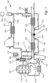
- Fig. 1 illustrates a waste heat recovery system 100 for a vehicle.
- the waste heat recovery system 100 comprises a tank pressure regulation system 300 for regulating the pressure in an expansion tank 102.
- the tank pressure regulation system 300 is described in further detail below with reference to subsequent drawings.
- the waste heat recovery system 100 comprises a condenser 108 arranged to receive and liquify the evaporated working fluid by heat exchange with a condenser cooling media.
- a pump 109 is arranged for circulating the working fluid in the waste heat recovery system, the pump 109 is connected to fluid communication lines downstream of the expansion tank 102 and upstream of the at least one heat exchanger 104.
- Rankine cycle is per se known in the art.
- the vaporized working fluid expands through a piston expander which generates work, W expander and corresponds to moving from point 3 to point 4 in the Rankine cycle diagram.
- the vaporized working fluid enters the condenser 108 where it is condensed through heat exchange with a cooling media to become a liquid working fluid again. This corresponds to moving from point 4 to point 1 in the Rankine cycle diagram of fig. 2 .
- the working fluid enters the expansion tank 102 through transfer pipe 110e.
- the pressure in the expansion tank 102 is regulated based on the condensation temperature of the working fluid. Further, the pressure in the expansion tank is regulated based on a temperature of a condenser cooling media of the condenser 108 upstream of the expansion tank 102 in the waste heat recovery system.
- the condenser cooling media is transferred to the condenser through transfer pipe 111a, withdraws heat from the vaporized working fluid, and is led from the condenser through transfer pipe 111b.
- the temperature of the condenser cooling media is measured along the transfer pipe 111a, preferably at the inlet 111c of the condenser 108 in order to obtain an accurate measure of the temperature of condenser cooling media in the condenser.
- the pressure in the expansion tank 102 is controlled such that a condensation temperature for the working fluid is equal to or exceed a present temperature of a condenser cooling media upstream of the expansion tank in the waste heat recovery system.
- Fig. 3A and Fig. 3B illustrate a diagram of a tank pressure regulation system 300 according to embodiments of the present disclosure.
- the tank pressure regulation system 300 comprises a compressor 302 comprising an inlet 304 for withdrawing gas and an outlet 306 for providing pressurized gas.
- the valve arrangement may be a four-way solenoid valve 310 although other types of valve arrangement are conceivable such as valve arrangements comprising more than one valve to achieve the same function as a four-way valve.
- a four-way solenoid valve is per se known in the art, but for sake of completeness, a spring 311 is arranged to provide a biasing force towards one of the configurations.
- the spring 311 may cause a force that strives for pushing the valve 310 into the configuration shown in fig. 3A , whereas the spring 311 is being compressed for forcing the valve 310 into the configuration shown in fig. 3B .
- the expansion tank 102 comprises an expandable container 102a and a rigid container 102b accommodating the expandable container 102a.
- the expandable container 102a which may be made from rubber or another flexible material is arranged to accommodate the working fluid 312.
- the expandable container 102a is adapted to be expandable such that the working fluid is allowed to expand therein.
- the rigid container 102b is arranged to be in fluid communication with the valve arrangement 310.
- the pressure in the rigid container 102b is controllable by the compressor 302 and valve arrangement 310.
- the rigid container 102b may be made from metal or hard plastic materials.
- the pressure in the rigid container 102b may be considered configured to be controllable by the compressor 302 and the valve arrangement 310.
- an air drier 322 for dehydrating air is connected on an air side port 324 of the valve arrangement 310.
- the air drier 322 advantageously dehydrates the air that is being withdrawn from ambient atmosphere and pressurized into the tank 102.
- valve arrangement may be configured to respond to a control signal to connect the compressor to the expansion tank to reduce the pressure in the expansion tank
Landscapes
- Engineering & Computer Science (AREA)
- Chemical & Material Sciences (AREA)
- Combustion & Propulsion (AREA)
- Mechanical Engineering (AREA)
- General Engineering & Computer Science (AREA)
- Engine Equipment That Uses Special Cycles (AREA)
Claims (15)
- Behälterdruckregelsystem (300) für ein Abwärmerückgewinnungssystem (100), umfassend einen Ausgleichsbehälter (102), um die Ausdehnung eines Arbeitsfluids des Abwärmerückgewinnungssystems (100) zuzulassen, einen Expander (106) zur Aufnahme von verdampftem Arbeitsfluid und zum Extrahieren von Arbeit durch die Ausdehnung des verdampften Arbeitsfluids, und einen Kondensator (108), der dazu angeordnet ist, das verdampfte Arbeitsfluid aufzunehmen, und zum Verflüssigen des verdampften Arbeitsfluids durch den Wärmeaustausch mit einem Kondensatorkühlmedium, wobei das Behälterdruckregelsystem (300) Folgendes umfasst:einen Verdichter (302), umfassend einen Einlass (304) zum Entnehmen von Gas und einen Auslass (306) zum Vorsehen von Druckgas, undeine Ventilanordnung (310), die mit dem Ausgleichsbehälter (102) und mit dem Einlass (304) und dem Auslass (306) des Verdichters (302) in Fluidverbindung bringbar ist, wobei die Ventilanordnung (310) während der Verwendung und wenn sie mit dem Verdichter (302) und dem Ausgleichsbehälter (102) verbunden ist, auf ein Steuersignal reagiert, um abwechselnd den Auslass (306) des Verdichters (302) mit dem Ausgleichsbehälter (102) zu verbinden, um dadurch den Druck im Ausgleichsbehälter (102) zu erhöhen, und den Einlass (304) des Verdichters (302) mit dem Ausgleichsbehälter (102) zu verbinden, um Gas aus dem Ausgleichsbehälter (102) zu entnehmen, um dadurch den Druck im Ausgleichsbehälter (102) zu verringern,wobei das Behälterdruckregelsystem dadurch gekennzeichnet ist, dass es ferner eine Steuereinheit (320) umfasst, die dazu ausgelegt ist, ein Signal zu empfangen, das einen vorhandenen Druck des Arbeitsfluids im Abwärmerückgewinnungssystem (100) angibt, und die vorhandene Kondensationstemperatur des Arbeitsfluids anhand des vorhandenen Drucks des Arbeitsfluids zu bestimmen und der Ventilanordnung (310) das Steuersignal zu senden, um den Druck im Ausgleichsbehälter (102) anhand der vorhandenen Kondensationstemperatur des Arbeitsfluids auf einen Druck unter Umgebungsdruck zu regeln.
- Behälterdruckregelsystem (300) nach Anspruch 1, wobei der Druck im Ausgleichsbehälter (102) ferner anhand der Temperatur eines Kondensatorkühlmediums des Kondensators (108) vor dem Ausgleichsbehälter (102) im Abwärmerückgewinnungssystem (100) geregelt wird.
- Behälterdruckregelsystem (300) nach Anspruch 2, wobei, wenn die Temperatur des Kondensatorkühlmediums abnimmt, die Ventilanordnung (310) reagiert, um den Verdichter (302) mit dem Ausgleichsbehälter (102) zu verbinden, um den Druck im Ausgleichsbehälter zu verringern.
- Behälterdruckregelsystem (300) nach einem der vorstehenden Ansprüche, wobei der Druck im Ausgleichsbehälter (102) derart gesteuert ist, dass die Kondensationstemperatur des Arbeitsfluids gleich oder höher als eine vorhandene Temperatur eines Kondensatorkühlmediums vor dem Ausgleichsbehälter (102) im Abwärmerückgewinnungssystem ist.
- Behälterdruckregelsystem (300) nach einem der vorstehenden Ansprüche, wobei der Druck im Ausgleichsbehälter (102) geregelt wird, um innerhalb eines Druckbereichs, einschließlich Umgebungsdruck, gehalten zu werden.
- Behälterdruckregelsystem (300) nach Anspruch 5, wobei der Druckbereich einen Druck unter Umgebungsdruck einschließt.
- Behälterdruckregelsystem (300) nach einem der vorstehenden Ansprüche, wobei die Ventilanordnung (310) ein Vier-Wege-Ventil (310) umfasst.
- Behälterdruckregelsystem (300) nach einem der vorstehenden Ansprüche, wobei der Ausgleichsbehälter (102) einen dehnbaren Behälter (102a) und einen den dehnbaren Behälter (102a) fassenden starren Behälter (102b) umfasst, wobei der dehnbare Behälter (102a) dazu angeordnet ist, das Arbeitsfluid zu fassen und der starre Behälter (102b) dazu angeordnet ist, mit der Ventilanordnung (310) in Fluidverbindung zu stehen, wobei der Druck im starren Behälter vom Verdichter (302) und von der Ventilanordnung (310) steuerbar ist.
- Behälterdruckregelsystem (300) nach einem der Ansprüche 2 bis 8, wobei das Kühlmedium im Kondensator (108) Umgebungsluft ist, wobei das Steuersignal auf der Temperatur der Umgebungsluft basiert.
- Behälterdruckregelsystem (300) nach einem der vorstehenden Ansprüche, wobei die Steuereinheit (320) dazu ausgelegt ist, Signale zu empfangen, die eine Temperatur des Kondensatorkühlmediums angeben und den vorhandenen Druck des Arbeitsfluids angeben, um dadurch die vorhandene Kondensationstemperatur des Arbeitsfluids zu bestimmen und der Ventilanordnung (310) anhand der empfangenen Signale das Steuersignal zu senden.
- Behälterdruckregelsystem (300) nach einem der vorstehenden Ansprüche, umfassend einen Lufttrockner (322) zum Dehydrieren von Luft, die aus der Umgebungsatmosphäre an einem luftseitigen Anschluss (324) der Ventilanordnung entnommen wird.
- Behälterdruckregelsystem (300) nach einem der vorstehenden Ansprüche, wobei die vorhandene Kondensationstemperatur anhand des vorhandenen Drucks des Arbeitsfluids im Abwärmerückgewinnungssystem (100) bestimmt wird.
- Abwärmerückgewinnungssystem (100) für ein Fahrzeug, wobei das Abwärmerückgewinnungssystem Folgendes umfasst:ein Behälterdruckregelsystem (300) nach einem der vorstehenden Ansprüche, mindestens einen Wärmetauscher (104) zum Verdampfen des Arbeitsfluids;einen Expander (106) zur Aufnahme von verdampftem Arbeitsfluid und zum Extrahieren von Arbeit durch die Ausdehnung des verdampften Arbeitsfluids;einen Kondensator (108), der dazu angeordnet ist, das verdampfte Arbeitsfluid aufzunehmen und das verdampfte Arbeitsfluid durch den Wärmeaustausch mit einem Kondensatorkühlmedium zu verflüssigen, undeine Pumpe (109) zum Zirkulieren des Arbeitsfluids im Abwärmerückgewinnungssystem, wobei die Pumpe mit Fluidkommunikationsleitungen nach dem Ausgleichsbehälter und vor dem mindestens einen Wärmetauscher verbunden ist.
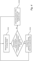
- Verfahren zum Steuern eines Behälterdruckregelsystems für ein Abwärmerückgewinnungssystem, umfassend einen Kondensator, der ein Kondensatorkühlmedium vor einem Ausgleichsbehälter aufweist, der dazu ausgelegt ist, die Ausdehnung eines Arbeitsfluids des Abwärmerückgewinnungssystems zuzulassen, wobei das Verfahren Folgendes umfasst:Erhöhen (S104) des Drucks des Arbeitsfluids im Ausgleichsbehälter, wenn die Temperatur des Kondensatorkühlmediums die vorhandene Kondensationstemperatur des Arbeitsfluids übersteigt,Verringern (S106) des Drucks des Arbeitsfluids im Ausgleichsbehälter, wenn die Temperatur des Kondensatorkühlmediums unter der vorhandenen Kondensationstemperatur des Arbeitsfluids liegt, wobei der Druck anhand der vorhandenen Kondensationstemperatur des Arbeitsfluids auf unter Umgebungsdruck verringert wird.
- Steuereinheit (320) zum Steuern eines Behälterdruckregelsystems (300) für ein Abwärmerückgewinnungssystem (100), umfassend einen Ausgleichsbehälter (102), um die Ausdehnung eines Arbeitsfluids des Abwärmerückgewinnungssystems zuzulassen, wobei die Steuereinheit dazu ausgelegt ist:ein Signal zu empfangen, das die Temperatur eines Kondensatorkühlmediums eines Kondensators (108), der vor dem Ausgleichsbehälter (102) im Abwärmerückgewinnungssystem (100) angeordnet ist, anzeigt;zu steuern, dass eine Ventilanordnung (310) in Fluidverbindung mit dem Ausgleichsbehälter (102), wenn das Signal eine Temperatur anzeigt, die eine vorhandene Kondensationstemperatur des Arbeitsfluids übersteigt, einen Auslass eines Verdichters (302) mit dem Ausgleichsbehälter (102) verbindet, um dadurch den Druck des Arbeitsfluids zu erhöhen, undzu steuern, dass die Ventilanordnung (310), wenn das Signal eine Temperatur anzeigt, die unter der vorhandenen Kondensationstemperatur des Arbeitsfluids liegt, den Einlass (304) des Verdichters (302) mit dem Ausgleichsbehälter (102) verbindet, um Gas aus dem Ausgleichsbehälter (102) zu entnehmen, um dadurch den Druck im Ausgleichsbehälter (302) zu verringern, wobei der Druck anhand der vorhandenen Kondensationstemperatur des Arbeitsfluids auf unter Umgebungsdruck verringert wird.
Priority Applications (1)
| Application Number | Priority Date | Filing Date | Title |
|---|---|---|---|
| EP20162674.4A EP3879082B1 (de) | 2020-03-12 | 2020-03-12 | Tankdruckregelsystem für ein abwärmerückgewinnungssystem |
Applications Claiming Priority (1)
| Application Number | Priority Date | Filing Date | Title |
|---|---|---|---|
| EP20162674.4A EP3879082B1 (de) | 2020-03-12 | 2020-03-12 | Tankdruckregelsystem für ein abwärmerückgewinnungssystem |
Publications (2)
| Publication Number | Publication Date |
|---|---|
| EP3879082A1 EP3879082A1 (de) | 2021-09-15 |
| EP3879082B1 true EP3879082B1 (de) | 2024-07-10 |
Family
ID=69810636
Family Applications (1)
| Application Number | Title | Priority Date | Filing Date |
|---|---|---|---|
| EP20162674.4A Active EP3879082B1 (de) | 2020-03-12 | 2020-03-12 | Tankdruckregelsystem für ein abwärmerückgewinnungssystem |
Country Status (1)
| Country | Link |
|---|---|
| EP (1) | EP3879082B1 (de) |
Family Cites Families (6)
| Publication number | Priority date | Publication date | Assignee | Title |
|---|---|---|---|---|
| FR2945574B1 (fr) * | 2009-05-13 | 2015-10-30 | Inst Francais Du Petrole | Dispositif de controle du fluide de travail circulant dans un circuit ferme fonctionnant selon un cycle de rankine et procede pour un tel dispositif |
| FR3020090B1 (fr) * | 2014-04-16 | 2019-04-12 | IFP Energies Nouvelles | Dispositif de controle d'un circuit ferme fonctionnant selon un cycle de rankine et procede utilisant un tel dispositif |
| DE102016222927A1 (de) * | 2016-11-21 | 2018-05-24 | Mahle International Gmbh | Wärmerückgewinnungseinrichtung |
| SE541729C2 (en) * | 2017-12-11 | 2019-12-03 | Scania Cv Ab | A device and a method for volume compensation and pressure control of a working medium in a WHR-system |
| SE541762C2 (en) * | 2017-12-11 | 2019-12-10 | Scania Cv Ab | An arrangement and a method for controlling a WHR-system |
| SE542807C2 (en) * | 2018-03-19 | 2020-07-14 | Scania Cv Ab | An arrangement and a method for controlling a shutdown phase of a WHR-system |
-
2020
- 2020-03-12 EP EP20162674.4A patent/EP3879082B1/de active Active
Also Published As
| Publication number | Publication date |
|---|---|
| EP3879082A1 (de) | 2021-09-15 |
Similar Documents
| Publication | Publication Date | Title |
|---|---|---|
| JP5462182B2 (ja) | 内燃機関の損失熱回収方法 | |
| US9879569B2 (en) | Method for operating a waste heat utilization device | |
| US8713939B2 (en) | Exhaust heat recovery system | |
| EP3402968B1 (de) | Kühlsystem für einen verbrennungsmotor und whr-system | |
| JP6660095B2 (ja) | ランキンサイクルに従って作動する閉ループを制御する装置およびそれを使用する方法 | |
| EP2554806A1 (de) | Abwärmeregenerationssystem | |
| KR101708109B1 (ko) | 폐열 회수 장치 및 폐열 회수 방법 | |
| KR20110041392A (ko) | 폐열 회생 시스템 | |
| US9784141B2 (en) | Method and system of controlling a thermodynamic system in a vehicle | |
| WO2017111886A1 (en) | Integrated control system for engine waste heat recovery using an organic rankine cycle | |
| EP3510264B1 (de) | Verfahren zur steuerung der temperatur einer kühlflüssigkeit in einem kühlsystem und kühlsystem | |
| EP3532715B1 (de) | Kühlsystem zur kühlung eines verbrennungsmotors und whr-system | |
| WO2016002425A1 (ja) | 廃熱回生システム | |
| EP3879082B1 (de) | Tankdruckregelsystem für ein abwärmerückgewinnungssystem | |
| CN105102769A (zh) | 废热回收系统和控制这种系统中所包括的正排量膨胀机的质量流率的方法 | |
| JP6996208B2 (ja) | ランキンサイクルシステム及びその制御方法 | |
| EP3402964B1 (de) | Kühlsystem für verbrennungsmotor und abwärmerückgewinnungsanlage | |
| CN103518053B (zh) | 用于内燃机废热利用的管道回路和用于运行该管道回路的方法 | |
| US9819193B2 (en) | Waste heat recovery system | |
| CN111527297A (zh) | 用于转换来自内燃机损失热的热能的装置 | |
| WO2020085968A1 (en) | Waste heat recovery system comprising receiver tank heatable by coolant fluid | |
| US20250102203A1 (en) | Heat pump for generating process heat | |
| WO2023203131A1 (en) | Compressor-expander system and method for operating the same | |
| EP3594569A1 (de) | Wärmerückgewinnungsvorrichtung | |
| SE542593C2 (en) | Waste heat recovery system comprising receiver tank connected to vapor side |
Legal Events
| Date | Code | Title | Description |
|---|---|---|---|
| PUAI | Public reference made under article 153(3) epc to a published international application that has entered the european phase |
Free format text: ORIGINAL CODE: 0009012 |
|
| STAA | Information on the status of an ep patent application or granted ep patent |
Free format text: STATUS: THE APPLICATION HAS BEEN PUBLISHED |
|
| AK | Designated contracting states |
Kind code of ref document: A1 Designated state(s): AL AT BE BG CH CY CZ DE DK EE ES FI FR GB GR HR HU IE IS IT LI LT LU LV MC MK MT NL NO PL PT RO RS SE SI SK SM TR |
|
| STAA | Information on the status of an ep patent application or granted ep patent |
Free format text: STATUS: REQUEST FOR EXAMINATION WAS MADE |
|
| 17P | Request for examination filed |
Effective date: 20220315 |
|
| RBV | Designated contracting states (corrected) |
Designated state(s): AL AT BE BG CH CY CZ DE DK EE ES FI FR GB GR HR HU IE IS IT LI LT LU LV MC MK MT NL NO PL PT RO RS SE SI SK SM TR |
|
| STAA | Information on the status of an ep patent application or granted ep patent |
Free format text: STATUS: EXAMINATION IS IN PROGRESS |
|
| 17Q | First examination report despatched |
Effective date: 20230404 |
|
| P01 | Opt-out of the competence of the unified patent court (upc) registered |
Effective date: 20230828 |
|
| GRAP | Despatch of communication of intention to grant a patent |
Free format text: ORIGINAL CODE: EPIDOSNIGR1 |
|
| STAA | Information on the status of an ep patent application or granted ep patent |
Free format text: STATUS: GRANT OF PATENT IS INTENDED |
|
| INTG | Intention to grant announced |
Effective date: 20240201 |
|
| GRAS | Grant fee paid |
Free format text: ORIGINAL CODE: EPIDOSNIGR3 |
|
| GRAA | (expected) grant |
Free format text: ORIGINAL CODE: 0009210 |
|
| STAA | Information on the status of an ep patent application or granted ep patent |
Free format text: STATUS: THE PATENT HAS BEEN GRANTED |
|
| AK | Designated contracting states |
Kind code of ref document: B1 Designated state(s): AL AT BE BG CH CY CZ DE DK EE ES FI FR GB GR HR HU IE IS IT LI LT LU LV MC MK MT NL NO PL PT RO RS SE SI SK SM TR |
|
| REG | Reference to a national code |
Ref country code: CH Ref legal event code: EP |
|
| REG | Reference to a national code |
Ref country code: DE Ref legal event code: R096 Ref document number: 602020033605 Country of ref document: DE |
|
| REG | Reference to a national code |
Ref country code: LT Ref legal event code: MG9D |
|
| REG | Reference to a national code |
Ref country code: NL Ref legal event code: MP Effective date: 20240710 |
|
| PG25 | Lapsed in a contracting state [announced via postgrant information from national office to epo] |
Ref country code: PT Free format text: LAPSE BECAUSE OF FAILURE TO SUBMIT A TRANSLATION OF THE DESCRIPTION OR TO PAY THE FEE WITHIN THE PRESCRIBED TIME-LIMIT Effective date: 20241111 |
|
| REG | Reference to a national code |
Ref country code: AT Ref legal event code: MK05 Ref document number: 1702195 Country of ref document: AT Kind code of ref document: T Effective date: 20240710 |
|
| PG25 | Lapsed in a contracting state [announced via postgrant information from national office to epo] |
Ref country code: NL Free format text: LAPSE BECAUSE OF FAILURE TO SUBMIT A TRANSLATION OF THE DESCRIPTION OR TO PAY THE FEE WITHIN THE PRESCRIBED TIME-LIMIT Effective date: 20240710 |
|
| PG25 | Lapsed in a contracting state [announced via postgrant information from national office to epo] |
Ref country code: PT Free format text: LAPSE BECAUSE OF FAILURE TO SUBMIT A TRANSLATION OF THE DESCRIPTION OR TO PAY THE FEE WITHIN THE PRESCRIBED TIME-LIMIT Effective date: 20241111 Ref country code: NL Free format text: LAPSE BECAUSE OF FAILURE TO SUBMIT A TRANSLATION OF THE DESCRIPTION OR TO PAY THE FEE WITHIN THE PRESCRIBED TIME-LIMIT Effective date: 20240710 |
|
| PG25 | Lapsed in a contracting state [announced via postgrant information from national office to epo] |
Ref country code: NO Free format text: LAPSE BECAUSE OF FAILURE TO SUBMIT A TRANSLATION OF THE DESCRIPTION OR TO PAY THE FEE WITHIN THE PRESCRIBED TIME-LIMIT Effective date: 20241010 |
|
| PG25 | Lapsed in a contracting state [announced via postgrant information from national office to epo] |
Ref country code: GR Free format text: LAPSE BECAUSE OF FAILURE TO SUBMIT A TRANSLATION OF THE DESCRIPTION OR TO PAY THE FEE WITHIN THE PRESCRIBED TIME-LIMIT Effective date: 20241011 Ref country code: FI Free format text: LAPSE BECAUSE OF FAILURE TO SUBMIT A TRANSLATION OF THE DESCRIPTION OR TO PAY THE FEE WITHIN THE PRESCRIBED TIME-LIMIT Effective date: 20240710 Ref country code: PL Free format text: LAPSE BECAUSE OF FAILURE TO SUBMIT A TRANSLATION OF THE DESCRIPTION OR TO PAY THE FEE WITHIN THE PRESCRIBED TIME-LIMIT Effective date: 20240710 |
|
| PG25 | Lapsed in a contracting state [announced via postgrant information from national office to epo] |
Ref country code: BG Free format text: LAPSE BECAUSE OF FAILURE TO SUBMIT A TRANSLATION OF THE DESCRIPTION OR TO PAY THE FEE WITHIN THE PRESCRIBED TIME-LIMIT Effective date: 20240710 |
|
| PG25 | Lapsed in a contracting state [announced via postgrant information from national office to epo] |
Ref country code: LV Free format text: LAPSE BECAUSE OF FAILURE TO SUBMIT A TRANSLATION OF THE DESCRIPTION OR TO PAY THE FEE WITHIN THE PRESCRIBED TIME-LIMIT Effective date: 20240710 |
|
| PG25 | Lapsed in a contracting state [announced via postgrant information from national office to epo] |
Ref country code: AT Free format text: LAPSE BECAUSE OF FAILURE TO SUBMIT A TRANSLATION OF THE DESCRIPTION OR TO PAY THE FEE WITHIN THE PRESCRIBED TIME-LIMIT Effective date: 20240710 Ref country code: IS Free format text: LAPSE BECAUSE OF FAILURE TO SUBMIT A TRANSLATION OF THE DESCRIPTION OR TO PAY THE FEE WITHIN THE PRESCRIBED TIME-LIMIT Effective date: 20241110 |
|
| PG25 | Lapsed in a contracting state [announced via postgrant information from national office to epo] |
Ref country code: HR Free format text: LAPSE BECAUSE OF FAILURE TO SUBMIT A TRANSLATION OF THE DESCRIPTION OR TO PAY THE FEE WITHIN THE PRESCRIBED TIME-LIMIT Effective date: 20240710 |
|
| PG25 | Lapsed in a contracting state [announced via postgrant information from national office to epo] |
Ref country code: ES Free format text: LAPSE BECAUSE OF FAILURE TO SUBMIT A TRANSLATION OF THE DESCRIPTION OR TO PAY THE FEE WITHIN THE PRESCRIBED TIME-LIMIT Effective date: 20240710 Ref country code: RS Free format text: LAPSE BECAUSE OF FAILURE TO SUBMIT A TRANSLATION OF THE DESCRIPTION OR TO PAY THE FEE WITHIN THE PRESCRIBED TIME-LIMIT Effective date: 20241010 |
|
| PG25 | Lapsed in a contracting state [announced via postgrant information from national office to epo] |
Ref country code: RS Free format text: LAPSE BECAUSE OF FAILURE TO SUBMIT A TRANSLATION OF THE DESCRIPTION OR TO PAY THE FEE WITHIN THE PRESCRIBED TIME-LIMIT Effective date: 20241010 Ref country code: PL Free format text: LAPSE BECAUSE OF FAILURE TO SUBMIT A TRANSLATION OF THE DESCRIPTION OR TO PAY THE FEE WITHIN THE PRESCRIBED TIME-LIMIT Effective date: 20240710 Ref country code: NO Free format text: LAPSE BECAUSE OF FAILURE TO SUBMIT A TRANSLATION OF THE DESCRIPTION OR TO PAY THE FEE WITHIN THE PRESCRIBED TIME-LIMIT Effective date: 20241010 Ref country code: LV Free format text: LAPSE BECAUSE OF FAILURE TO SUBMIT A TRANSLATION OF THE DESCRIPTION OR TO PAY THE FEE WITHIN THE PRESCRIBED TIME-LIMIT Effective date: 20240710 Ref country code: IS Free format text: LAPSE BECAUSE OF FAILURE TO SUBMIT A TRANSLATION OF THE DESCRIPTION OR TO PAY THE FEE WITHIN THE PRESCRIBED TIME-LIMIT Effective date: 20241110 Ref country code: HR Free format text: LAPSE BECAUSE OF FAILURE TO SUBMIT A TRANSLATION OF THE DESCRIPTION OR TO PAY THE FEE WITHIN THE PRESCRIBED TIME-LIMIT Effective date: 20240710 Ref country code: GR Free format text: LAPSE BECAUSE OF FAILURE TO SUBMIT A TRANSLATION OF THE DESCRIPTION OR TO PAY THE FEE WITHIN THE PRESCRIBED TIME-LIMIT Effective date: 20241011 Ref country code: FI Free format text: LAPSE BECAUSE OF FAILURE TO SUBMIT A TRANSLATION OF THE DESCRIPTION OR TO PAY THE FEE WITHIN THE PRESCRIBED TIME-LIMIT Effective date: 20240710 Ref country code: ES Free format text: LAPSE BECAUSE OF FAILURE TO SUBMIT A TRANSLATION OF THE DESCRIPTION OR TO PAY THE FEE WITHIN THE PRESCRIBED TIME-LIMIT Effective date: 20240710 Ref country code: BG Free format text: LAPSE BECAUSE OF FAILURE TO SUBMIT A TRANSLATION OF THE DESCRIPTION OR TO PAY THE FEE WITHIN THE PRESCRIBED TIME-LIMIT Effective date: 20240710 Ref country code: AT Free format text: LAPSE BECAUSE OF FAILURE TO SUBMIT A TRANSLATION OF THE DESCRIPTION OR TO PAY THE FEE WITHIN THE PRESCRIBED TIME-LIMIT Effective date: 20240710 |
|
| REG | Reference to a national code |
Ref country code: DE Ref legal event code: R097 Ref document number: 602020033605 Country of ref document: DE |
|
| PG25 | Lapsed in a contracting state [announced via postgrant information from national office to epo] |
Ref country code: RO Free format text: LAPSE BECAUSE OF FAILURE TO SUBMIT A TRANSLATION OF THE DESCRIPTION OR TO PAY THE FEE WITHIN THE PRESCRIBED TIME-LIMIT Effective date: 20240710 Ref country code: DK Free format text: LAPSE BECAUSE OF FAILURE TO SUBMIT A TRANSLATION OF THE DESCRIPTION OR TO PAY THE FEE WITHIN THE PRESCRIBED TIME-LIMIT Effective date: 20240710 Ref country code: SM Free format text: LAPSE BECAUSE OF FAILURE TO SUBMIT A TRANSLATION OF THE DESCRIPTION OR TO PAY THE FEE WITHIN THE PRESCRIBED TIME-LIMIT Effective date: 20240710 |
|
| PG25 | Lapsed in a contracting state [announced via postgrant information from national office to epo] |
Ref country code: EE Free format text: LAPSE BECAUSE OF FAILURE TO SUBMIT A TRANSLATION OF THE DESCRIPTION OR TO PAY THE FEE WITHIN THE PRESCRIBED TIME-LIMIT Effective date: 20240710 |
|
| PG25 | Lapsed in a contracting state [announced via postgrant information from national office to epo] |
Ref country code: CZ Free format text: LAPSE BECAUSE OF FAILURE TO SUBMIT A TRANSLATION OF THE DESCRIPTION OR TO PAY THE FEE WITHIN THE PRESCRIBED TIME-LIMIT Effective date: 20240710 |
|
| PG25 | Lapsed in a contracting state [announced via postgrant information from national office to epo] |
Ref country code: IT Free format text: LAPSE BECAUSE OF FAILURE TO SUBMIT A TRANSLATION OF THE DESCRIPTION OR TO PAY THE FEE WITHIN THE PRESCRIBED TIME-LIMIT Effective date: 20240710 Ref country code: SK Free format text: LAPSE BECAUSE OF FAILURE TO SUBMIT A TRANSLATION OF THE DESCRIPTION OR TO PAY THE FEE WITHIN THE PRESCRIBED TIME-LIMIT Effective date: 20240710 |
|
| PLBE | No opposition filed within time limit |
Free format text: ORIGINAL CODE: 0009261 |
|
| STAA | Information on the status of an ep patent application or granted ep patent |
Free format text: STATUS: NO OPPOSITION FILED WITHIN TIME LIMIT |
|
| 26N | No opposition filed |
Effective date: 20250411 |
|
| PG25 | Lapsed in a contracting state [announced via postgrant information from national office to epo] |
Ref country code: SE Free format text: LAPSE BECAUSE OF FAILURE TO SUBMIT A TRANSLATION OF THE DESCRIPTION OR TO PAY THE FEE WITHIN THE PRESCRIBED TIME-LIMIT Effective date: 20240710 |
|
| PG25 | Lapsed in a contracting state [announced via postgrant information from national office to epo] |
Ref country code: MC Free format text: LAPSE BECAUSE OF FAILURE TO SUBMIT A TRANSLATION OF THE DESCRIPTION OR TO PAY THE FEE WITHIN THE PRESCRIBED TIME-LIMIT Effective date: 20240710 |
|
| REG | Reference to a national code |
Ref country code: CH Ref legal event code: H13 Free format text: ST27 STATUS EVENT CODE: U-0-0-H10-H13 (AS PROVIDED BY THE NATIONAL OFFICE) Effective date: 20251023 |
|
| PG25 | Lapsed in a contracting state [announced via postgrant information from national office to epo] |
Ref country code: LU Free format text: LAPSE BECAUSE OF NON-PAYMENT OF DUE FEES Effective date: 20250312 |
|
| REG | Reference to a national code |
Ref country code: BE Ref legal event code: MM Effective date: 20250331 |
|
| PG25 | Lapsed in a contracting state [announced via postgrant information from national office to epo] |
Ref country code: BE Free format text: LAPSE BECAUSE OF NON-PAYMENT OF DUE FEES Effective date: 20250331 |
|
| PG25 | Lapsed in a contracting state [announced via postgrant information from national office to epo] |
Ref country code: CH Free format text: LAPSE BECAUSE OF NON-PAYMENT OF DUE FEES Effective date: 20250331 |
|
| PG25 | Lapsed in a contracting state [announced via postgrant information from national office to epo] |
Ref country code: IE Free format text: LAPSE BECAUSE OF NON-PAYMENT OF DUE FEES Effective date: 20250312 |
|
| PGFP | Annual fee paid to national office [announced via postgrant information from national office to epo] |
Ref country code: GB Payment date: 20260219 Year of fee payment: 7 |
|
| PGFP | Annual fee paid to national office [announced via postgrant information from national office to epo] |
Ref country code: DE Payment date: 20260219 Year of fee payment: 7 |
|
| PGFP | Annual fee paid to national office [announced via postgrant information from national office to epo] |
Ref country code: FR Payment date: 20260219 Year of fee payment: 7 |