EP3879074B1 - Heckkonus für eine gasturbine und montierter generator - Google Patents
Heckkonus für eine gasturbine und montierter generator Download PDFInfo
- Publication number
- EP3879074B1 EP3879074B1 EP21156912.4A EP21156912A EP3879074B1 EP 3879074 B1 EP3879074 B1 EP 3879074B1 EP 21156912 A EP21156912 A EP 21156912A EP 3879074 B1 EP3879074 B1 EP 3879074B1
- Authority
- EP
- European Patent Office
- Prior art keywords
- casing
- tail cone
- adapter
- generator housing
- gas turbine
- Prior art date
- Legal status (The legal status is an assumption and is not a legal conclusion. Google has not performed a legal analysis and makes no representation as to the accuracy of the status listed.)
- Active
Links
Images


Classifications
-
- F—MECHANICAL ENGINEERING; LIGHTING; HEATING; WEAPONS; BLASTING
- F01—MACHINES OR ENGINES IN GENERAL; ENGINE PLANTS IN GENERAL; STEAM ENGINES
- F01D—NON-POSITIVE DISPLACEMENT MACHINES OR ENGINES, e.g. STEAM TURBINES
- F01D15/00—Adaptations of machines or engines for special use; Combinations of engines with devices driven thereby
- F01D15/10—Adaptations for driving, or combinations with, electric generators
-
- H—ELECTRICITY
- H02—GENERATION; CONVERSION OR DISTRIBUTION OF ELECTRIC POWER
- H02K—DYNAMO-ELECTRIC MACHINES
- H02K5/00—Casings; Enclosures; Supports
- H02K5/04—Casings or enclosures characterised by the shape, form or construction thereof
- H02K5/22—Auxiliary parts of casings not covered by groups H02K5/06-H02K5/20, e.g. shaped to form connection boxes or terminal boxes
- H02K5/225—Terminal boxes or connection arrangements
-
- F—MECHANICAL ENGINEERING; LIGHTING; HEATING; WEAPONS; BLASTING
- F01—MACHINES OR ENGINES IN GENERAL; ENGINE PLANTS IN GENERAL; STEAM ENGINES
- F01D—NON-POSITIVE DISPLACEMENT MACHINES OR ENGINES, e.g. STEAM TURBINES
- F01D25/00—Component parts, details, or accessories, not provided for in, or of interest apart from, other groups
- F01D25/24—Casings; Casing parts, e.g. diaphragms, casing fastenings
- F01D25/243—Flange connections; Bolting arrangements
-
- F—MECHANICAL ENGINEERING; LIGHTING; HEATING; WEAPONS; BLASTING
- F01—MACHINES OR ENGINES IN GENERAL; ENGINE PLANTS IN GENERAL; STEAM ENGINES
- F01D—NON-POSITIVE DISPLACEMENT MACHINES OR ENGINES, e.g. STEAM TURBINES
- F01D25/00—Component parts, details, or accessories, not provided for in, or of interest apart from, other groups
- F01D25/30—Exhaust heads, chambers, or the like
-
- F—MECHANICAL ENGINEERING; LIGHTING; HEATING; WEAPONS; BLASTING
- F01—MACHINES OR ENGINES IN GENERAL; ENGINE PLANTS IN GENERAL; STEAM ENGINES
- F01D—NON-POSITIVE DISPLACEMENT MACHINES OR ENGINES, e.g. STEAM TURBINES
- F01D9/00—Stators
- F01D9/06—Fluid supply conduits to nozzles or the like
- F01D9/065—Fluid supply or removal conduits traversing the working fluid flow, e.g. for lubrication-, cooling-, or sealing fluids
-
- H—ELECTRICITY
- H02—GENERATION; CONVERSION OR DISTRIBUTION OF ELECTRIC POWER
- H02K—DYNAMO-ELECTRIC MACHINES
- H02K7/00—Arrangements for handling mechanical energy structurally associated with dynamo-electric machines, e.g. structural association with mechanical driving motors or auxiliary dynamo-electric machines
- H02K7/18—Structural association of electric generators with mechanical driving motors, e.g. with turbines
- H02K7/1807—Rotary generators
- H02K7/1823—Rotary generators structurally associated with turbines or similar engines
-
- F—MECHANICAL ENGINEERING; LIGHTING; HEATING; WEAPONS; BLASTING
- F01—MACHINES OR ENGINES IN GENERAL; ENGINE PLANTS IN GENERAL; STEAM ENGINES
- F01D—NON-POSITIVE DISPLACEMENT MACHINES OR ENGINES, e.g. STEAM TURBINES
- F01D9/00—Stators
-
- F—MECHANICAL ENGINEERING; LIGHTING; HEATING; WEAPONS; BLASTING
- F02—COMBUSTION ENGINES; HOT-GAS OR COMBUSTION-PRODUCT ENGINE PLANTS
- F02C—GAS-TURBINE PLANTS; AIR INTAKES FOR JET-PROPULSION PLANTS; CONTROLLING FUEL SUPPLY IN AIR-BREATHING JET-PROPULSION PLANTS
- F02C6/00—Plural gas-turbine plants; Combinations of gas-turbine plants with other apparatus; Adaptations of gas-turbine plants for special use
-
- F—MECHANICAL ENGINEERING; LIGHTING; HEATING; WEAPONS; BLASTING
- F05—INDEXING SCHEMES RELATING TO ENGINES OR PUMPS IN VARIOUS SUBCLASSES OF CLASSES F01-F04
- F05D—INDEXING SCHEME FOR ASPECTS RELATING TO NON-POSITIVE-DISPLACEMENT MACHINES OR ENGINES, GAS-TURBINES OR JET-PROPULSION PLANTS
- F05D2220/00—Application
- F05D2220/70—Application in combination with
- F05D2220/76—Application in combination with an electrical generator
Definitions
- the air of the core flow path C is compressed by the low pressure compressor 44 then the high pressure compressor 52, mixed and burned with fuel in the combustor 56, then expanded over the high pressure turbine 54 and the low pressure turbine 46.
- the turbine section 28 rotationally drives the respective low speed spool 30 and high speed spool 32 in response to the expansion. It will be appreciated that each of the positions of the fan section 22, the compressor section 24, the combustor section 26, and the turbine section 28 may be varied, depending on the specific engine configuration and/or application.
- the connectors for the electric generator When mounting the electric generator within the interior space of a tail cone, the connectors for the electric generator must enable connection from the generator to other engine and/or aircraft systems.
- Such electric generator may require fluid inputs (e.g., air and/or liquid) for the purpose of cooling and lubrication (can include input and output conduits).
- the electricity must be directed along electrical conductors to deliver the electricity to one or more desired locations (e.g., on the gas turbine or elsewhere on the aircraft).
- Conventional terminal blocks are not suitable for use in this tail cone configuration. This is because conventional terminal blocks are too large and cannot fit within the space at the tail cone.
- a tail cone assembly 200 is shown.
- the tail cone assembly 200 is configured to house an electric generator within a generator housing 202.
- the generator housing 202 is supported within a gas turbine engine by a first casing 204.
- struts 206 extend between the first casing 204 and a second casing 208.
- the space between the first casing 204 and the second casing may define the hot gas exhaust from the gas turbine engine (e.g., core flow path C shown in FIG. 1 ).
- a third casing may be arranged radially outward from the second casing, with the space between the second casing 208 and the third casing defining an exhaust of bypass air (e.g., bypass flow path B shown in FIG. 1 ).
- the terminal block 210 cannot fit within a reasonable space around the generator housing 202, and thus is shown extending through the first casing 204 and into the exhaust area of the core flow path. Furthermore, as shown, cabling for electrical connections is not viable either, as such cables would need to extend through and be exposed to the hot exhaust gases. This is due in part to the relatively narrow or small area in which the generator housing 202 is installed, and also due in part to the relatively small circumference of the generator housing 202. That is, the generator housing 202 does not provide sufficient surface area for the proper installation and use of the terminal block 210, as shown.
- embodiments of the present disclosure are directed to improved systems and configurations that allow for the use of a tail cone-mounted electric generator and electrical connections thereto.
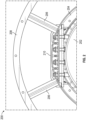
- FIGS. 3A-3C schematic illustrations of a tail cone assembly 300 in accordance with an embodiment of the present disclosure are shown.
- FIG. 3A is an aft-facing view of the tail cone assembly 300
- FIG. 3B is a forward-facing isometric illustration of the tail cone assembly 300
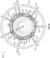
- FIG. 3C is an aft-facing isometric illustration of the tail cone assembly 300.
- the tail cone assembly 300 includes an electric generator installed within a generator housing 302 that is arranged within a tail cone 303 and along an axis of a gas turbine engine, with the electric generator having an input shaft 304 that is configured to operably connect to a low spool of the gas turbine engine.
- the low spool of the gas turbine engine may be configured to drive operation of the electric generator to generate power which may be distributed to other systems of the gas turbine engine and/or of an aircraft.
- the generator housing 302 is mounted within a first casing 306 of the gas turbine engine. Radially outward from the first casing 306 is a second casing 308, and radially outward from the second casing 308 is a third casing 310 (shown in FIG. 3A ).
- the space between the first casing 306 and the second casing 308 defines an core exhaust area 312 of a core flow path through the gas turbine engine and space between the second casing 308 and the third casing 310 defines a bypass exhaust area 314 of a bypass flow path, as shown in FIG. 3A .
- a plurality of hollow struts 316 extend between the first casing 306 and the second casing 308.
- first casing 306 is an inner casing
- second casing 308 is a middle casing
- third casing 310 is an outer casing, with each casing description made relative to a radial line extending from an engine axis.
- the electric generator housed within the generator housing 302 can be operably connected to other systems using one or more types of conduits, cables, and/or connectors.
- the electric generator has four sets of electrical conductors 318 operably (and electrically) connected thereto along with an oil input line 320, an air input line 322, and an oil scavenge line 324.
- the tail cone assembly 300 includes seven hollow struts 316.
- the hollow struts 316 are arranged circumferentially about or relative to the generator housing 302 at specific locations and aligned therewith, as described herein.
- each of the hollow struts 316 are configured to contain and protect the electrical conductors 318, one hollow strut 316 each is used to contain and protect the oil input line 320, the air input line 322, and the oil scavenge line 324.
- each of the electrical conductors 318, the oil input line 320, the air input line 322, and the oil scavenge line 324 may pass through the core exhaust area 312 without being directly, and adversely, impacted thereby.
- such elements are housed such that they are contained within substantially aerodynamic structures (i.e., the hollow struts 316), and thus do not adversely impact the exhaust stream efficiencies.
- the circumferential position or location of the hollow struts allows for an easy installation of the internal components and ease of connection and/or interfacing with the generator housing 302 and/or elements/structures housed within the generator housing 302. This is achieved, in part, for example, due to the circumferential alignment of the hollow struts with a connector on the generator housing.
- the electrical conductors 318, the oil input line 320, the air input line 322, and the oil scavenge line 324 pass through the bypass exhaust area 314.
- This configuration is not to be limiting.
- Such configuration may have one or more of the electrical conductors 318, the oil input line 320, the air input line 322, and the oil scavenge line 324 extending axially along the second casing 308 (i.e., in-and-out of the page of FIG. 3A ).
- the illustrative configuration is not to be limiting, but rather is merely for illustrative and explanatory purposes.
- the electrical conductors 318 there are four electrical conductors 318 that electrically connect to the electric generator within the generator housing 302.
- the four electrical conductors 318 are configured to securely engage with, and electrically engage with, respective terminal posts arranged on the exterior of the generator housing 302.
- the terminal posts are arranged at locations on the exterior of the generator housing 302 such that when installed into a gas turbine engine, the terminal posts will align with the hollow struts 316.
- the electrical conductors 318 may pass directly through the hollow struts 316 and electrically connect with the terminal posts.
- the electrical conductors 318 are formed of a group of three wires or cables. Each wire or cable of the electrical conductors 318 may be arranged as one of A, B, or C Phase, such that at each terminal post a set of A, B, C Phases are connected to the electric generator housed within the generator housing 302.
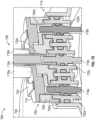
- FIG. 4 a schematic cross-sectional illustration of a tail cone assembly 400 in accordance with an embodiment of the present disclosure is shown.
- FIG. 4 illustrates a generator housing 402 with an electric generator 404 installed therein.
- the electric generator 404 includes an input shaft 406 that operably connects to a low spool shaft 408 of a gas turbine engine and is arranged along a longitudinal axis A x of the generator housing 402.
- the longitudinal axis A x of the generator housing 402 will align with the engine longitudinal axis.
- Other examples of such electric generators are disclosed in: U.S. Patent Application Serial No.
- FIGS. 5A-5C schematic illustrations of a tail cone assembly 500 in accordance with an embodiment of the present disclosure are shown.
- FIG. 5A is an aft-facing isometric view of the tail cone assembly 500 without electrical connections
- FIG. 5B is an aft-facing isometric illustration of the tail cone assembly 500 with electrical connections shown
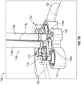
- FIG. 5C is a forward-facing illustration of the tail cone assembly 500 as installed within a portion of a gas turbine engine.
- the tail cone assembly 500 includes an electric generator installed within a generator housing 502 that is arranged along an axis of a gas turbine engine, with the electric generator having an input shaft 504 that is configured to operably connect to a low spool of the gas turbine engine.
- the low spool of the gas turbine engine may be configured to drive operation of the electric generator to generate power which may be distributed to other systems of the gas turbine engine and/or of an aircraft.
- the generator housing 502 includes a plurality of different connectors.
- the generator housing 502 includes a number of electrical connectors 506 (e.g., terminal posts), and as shown are arranged as sets of three wires or cables (e.g., A, B, C, phases).
- the generator housing 502 includes one or more fluid connectors 508 which can provide for fluid connection to one or more sources of fluid (e.g., oil inlet, air inlet, scavenge outlet, etc.).
- FIG. 5B illustrates electrical conductors 510 that connect to the electrical connectors 506 by a respective adapter 512.
- the adapters 512 are configured to receive the electrical conductors 510 and provide for an electrical interface between the electrical conductors 510 and the electric generator housed within the generator housing 502. As such, the adapters 512 may be considered terminal blocks of the system.
- the adapters 512 can provide fixed connection between the electrical conductors 510 and a respective electrical connector 506 of the generator housing 502.
- the adapters 512 are configured to enable both physical and electrical connection between the electrical conductors 510 and a respective electrical connector 506.
- FIG. 5C illustrates the tail cone assembly 500 with the generator housing 502 and interior electric generator installed relative to casings of a gas turbine engine.
- the generator housing 502 is installed radially inward from a first casing 514, which in turn is arranged radially inward from a second casing 516, similar to that shown and described above.
- a number of hollow struts 518 are arranged to connect the first casing 514 to the second casing 516.
- the electrical conductors 510 are arranged to pass through the hollow struts 518 from the second casing 516 to the first casing 514 and to engage with a respective electrical connector 506.
- An adapter 520 is arranged between each electrical conductor 510 and a respective electrical connector 506 to enable electrical connection between the electrical conductors 510 and the electric generator installed and housed within the generator housing 502.
- various fluid lines 522 are installed through respective hollow struts 518 to provide for fluid connections with the electric generator installed and housed within the generator housing 502.
- Such fluid lines 522 may provide for inlets and/or outlets for fluids such as, without limitation, oil and air.
- FIGS. 6A-6B schematic illustrations of a part of a tail cone assembly 600 in accordance with an embodiment of the present disclosure are shown.
- FIG. 6A illustrates a partially transparent isometric illustration of a portion of the tail cone assembly 600 and
- FIG. 6B is a radially inward view of the portion of the tail cone assembly 600.
- the tail cone assembly 600 may be similar to that shown and described above.
- a generator housing 602 is shown radially inward from an first casing 604 and a second casing 606, similar to that shown and described above.
- a hollow strut 608 extends between the first casing 604 and the second casing 606.
- an electrical conductor 610 passes through the hollow strut 608.
- the electrical conductor 610 in these illustrations comprises three separate wires or cables, and may be configured as a three-phase electrical conductor.
- the hollow strut 608 defines an interior cavity 612 that openly connects to a first casing opening 614 of the first casing 604 and to a second casing opening 616 of the second casing 606.
- an open path or conduit is defined between the first casing 604 and the second casing 606 through which the electrical conductor 610 can pass.
- an adapter 620 is arranged to fit within the interior cavity 612 of the hollow strut 608 and within the first casing opening 614 of the first casing 604.
- the adapter 620 provides for an electrical interface or connection between the electrical conductor 610 and an electrical connector of the generator housing 602.
- FIGS. 7A-7D schematic illustrations of a portion of a tail cone assembly 700 in accordance with an embodiment of the present disclosure are shown.
- FIG. 7A is an isometric illustration of an adapter 702 shown relative to a generator housing 704 to enable connection of an electrical conductor 706 to an electric generator housed within the generator housing 704.
- FIG. 7B illustrates a partial transparent illustration of the adapter 702 as connected to an electrical conductor 706 of the generator housing 704.
- FIG. 7C illustrates a top down cross-sectional illustration of the adapter 702 as viewed along the line C-C of FIG. 7A .
- FIG. 7D is a cross-sectional illustration of the adapter 702 as viewed along the line D-D of FIG. 7C .
- the tail cone assembly 700 may be similar to that shown and described above.
- the adapter 602 and the electrical conductor 706 may be configured to fit within an interior cavity of a hollow strut, such as shown above.
- the adapter 702 includes an adapter body 708 and an adapter cover 710.
- the adapter cover 710 may be removably attached to the adapter body 708 by one or more fasteners 712.
- the electrical conductor 706 may pass through the adapter cover 710 to enable an electrical connection within the adapter 702, as described below.
- the adapter body 708 is configured to be installed to an electrical connector 714 of the generator housing 706.
- One or more electrical pins 716a, 716b, 716c are configured to extend from the electric generator and pass through the electrical connector 714 of the generator housing 706.
- the electrical conductor 706 includes respective wires 718a, 718b, 718c, which are configured to each electrically connect to one of the electrical pins 716a, 716b, 716c through an electrical connection within the adapter 702.
- one or more bus bars 720a, 720b, 720c are arranged within the adapter 702 to provide an electrical connection between each wire 718a, 718b, 718c of the electrical conductor 706 and the electrical pins 716a, 716b, 716c.
- an electrical connection can be achieved between the electrical conductor 706 and an electric generator within the generator housing 704.
- the adapter housing 708 and the adapter cover 710 may be made of an electrically insulating material such that the electrical paths through the adapter 702 is defined by respective sets of wires 718a, 718b, 718c, bus bars 720a, 720b, 720c, and electrical pins 716a, 716b, 716c.
- the electrical pins 716a, 716b, 716c may be supported within the electrical connector 714 by respective pin supports 722a, 722b, 722c, as shown in FIG. 7D .
- the adapter 702 may be attached to or otherwise connected to the generator housing 702 by an attachment mechanism.
- the attachment mechanism is provided by a bracket 724 that can be fastened to a bracket support 726 using one or more fasteners 728.
- the bracket 724 is a separate element from the adapter 702.
- the bracket functionality may be integrated into one or both of the adapter body 708 and the adapter cover 710.
- the adapter body 708 may be formed to provide for a snap-connection or other direct connection between the adapter body and the generator housing and/or the electrical connector thereof.
- embodiments of the present disclosure can enable improved electrical connection and power supply and distribution on an engine and/or aircraft.
- embodiments described herein may enable installation of power sources within limited-access locations, such as tail cones of gas turbine engines.
- the environment and installation limits the size and nature of components installed.
- a tail cone can be hollow and enable the installation of an electric generator therein.
- Embodiments described herein enable efficient electrical routing by using adapters and electrical connectors that allow for electrical conductors to be installed and pass through hollow struts that are arranged about the tail cone of the gas turbine engine.
- a generator housing can be configured to multiple electrical connectors (e.g., terminal posts) that allow for electrical connection to an electric generator within the tail cone.
- the electrical connectors can be configured to electrical pins to provide three-phase electrical transmission, and thus three-phase can be distributed from the electric generator at multiple locations.
- Such multiple electrical connectors can improve power quality and reduce electromagnetic interference within the power system.
- the terms "about” and “substantially” are intended to include the degree of error associated with measurement of the particular quantity based upon the equipment available at the time of filing the application. For example, the terms may include a range of ⁇ 8%, or 5%, or 2% of a given value or other percentage change as will be appreciated by those of skill in the art for the particular measurement and/or dimensions referred to herein.
Landscapes
- Engineering & Computer Science (AREA)
- Mechanical Engineering (AREA)
- General Engineering & Computer Science (AREA)
- Power Engineering (AREA)
- Physics & Mathematics (AREA)
- Fluid Mechanics (AREA)
- Connection Of Motors, Electrical Generators, Mechanical Devices, And The Like (AREA)
- Chemical & Material Sciences (AREA)
- Combustion & Propulsion (AREA)
Claims (14)
- Heckkonusbaugruppe (500) für ein Gasturbinentriebwerk, umfassend:einen Heckkonus;ein Generatorgehäuse (502), das einen elektrischen Verbinder (506) aufweist, wobei das Generatorgehäuse eine Längsachse definiert, wobei das Generatorgehäuse innerhalb des Heckkonus angeordnet ist;eine erste Verkleidung (514), die relativ zu der Längsachse radial auswärts von dem Generatorgehäuse angeordnet ist, wobei sich der Heckkonus axial von der ersten Verkleidung erstreckt;eine zweite Verkleidung (516), die relativ zu der Längsachse radial auswärts von der ersten Verkleidung angeordnet ist;eine hohle Strebe (518), die sich radial zwischen der ersten Verkleidung und der zweiten Verkleidung erstreckt und einen Innenhohlraum definiert, wobei die hohle Strebe in Umfangsrichtung relativ zu der Längsachse an einer Stelle liegt, die in Umfangsrichtung mit dem elektrischen Verbinder des Generatorgehäuses ausgerichtet ist;einen elektrischen Leiter (510), der innerhalb des Innenhohlraums der hohlen Strebe angeordnet ist; undeinen Adapter (512), der dazu konfiguriert ist, den elektrischen Leiter elektrisch mit dem elektrischen Verbinder des Generatorgehäuses zu verbinden, wobei der Adapter eine längliche Struktur ist, die in den Innenhohlraum der hohlen Strebe passt.
- Heckkonusbaugruppe nach Anspruch 1, ferner umfassend einen innerhalb des Generatorgehäuses eingebauten elektrischen Generator.
- Heckkonusbaugruppe nach einem der vorhergehenden Ansprüche, wobei der elektrische Leiter (510) ein dreiphasiger elektrischer Leiter ist, der drei Drähte aufweist, und wobei:der elektrische Verbinder (506) drei elektrische Stifte umfasst; undder Adapter (512) drei Sammelschienen umfasst, die angeordnet sind, um jeweils einen der drei Drähte mit einem der drei elektrischen Stifte zu verbinden.
- Heckkonusbaugruppe nach einem der vorhergehenden Ansprüche, ferner umfassend:mindestens eine zusätzliche hohle Strebe (518), die sich radial zwischen der ersten Verkleidung und der zweiten Verkleidung erstreckt und einen Innenhohlraum definiert, wobei die mindestens eine zusätzliche hohle Strebe in Umfangsrichtung relativ zu der Längsachse an einer Stelle liegt, die radial mit mindestens einem zusätzlichen elektrischen Verbinder des Generatorgehäuses ausgerichtet ist;mindestens einen zusätzlichen elektrischen Leiter (510), der innerhalb des Innenhohlraums der mindestens einen zusätzlichen hohlen Strebe angeordnet ist; undmindestens einen zusätzlichen Adapter (512), der dazu konfiguriert ist, den mindestens einen zusätzlichen elektrischen Leiter elektrisch mit dem mindestens einen zusätzlichen elektrischen Verbinder zu verbinden.
- Heckkonusbaugruppe nach einem der vorhergehenden Ansprüche, ferner umfassend eine Halterung (724), die dazu konfiguriert ist, den Adapter fest an dem Generatorgehäuse zu befestigen.
- Heckkonusbaugruppe nach einem der vorhergehenden Ansprüche, wobei der Adapter (512) einen Adapterkörper (708) und eine Adapterabdeckung (710) umfasst und wobei der Adapterkörper (708) dazu konfiguriert ist, direkt mit dem Generatorgehäuse verbunden zu sein; und/oder wobei der Adapterkörper (708) und die Adapterabdeckung (710) elektrisch isolierend sind.
- Gasturbinentriebwerk, umfassend eine Niederdruckspulenwelle (408), die entlang einer Triebwerkslängsachse angeordnet ist; und
eine Heckkonusbaugruppe (500) nach Anspruch 1. - Gasturbinentriebwerk nach Anspruch 7, ferner umfassend einen innerhalb des Generatorgehäuses eingebauten elektrischen Generator, wobei der elektrische Generator mit der Niederdruckspulenwelle (408) wirkverbunden ist.
- Gasturbinentriebwerk nach Anspruch 7 oder 8, wobei der Adapter (512) innerhalb des Innenhohlraums der hohlen Strebe angeordnet ist.
- Gasturbinentriebwerk nach einem der Ansprüche 7-9, wobei der elektrische Leiter (510) ein dreiphasiger elektrischer Leiter ist, der drei Drähte aufweist.
- Gasturbinentriebwerk nach einem der Ansprüche 7-10, ferner umfassend eine dritte Verkleidung (310), die relativ zu der Längsachse radial auswärts von der zweiten Verkleidung angeordnet ist, wobei ein Raum zwischen der ersten Verkleidung und der zweiten Verkleidung ein Kernströmungs-Ausströmbereich ist und ein Raum zwischen der zweiten Verkleidung und der dritten Verkleidung ein Bypassströmungs-Ausströmbereich ist.
- Gasturbinentriebwerk nach einem der Ansprüche 7-11, ferner umfassend:mindestens eine zusätzliche eine hohle Strebe (518), die sich radial zwischen der ersten Verkleidung und der zweiten Verkleidung erstreckt und einen Innenhohlraum definiert, wobei die mindestens eine zusätzliche hohle Strebe in Umfangsrichtung relativ zu der Längsachse an einer Stelle liegt, die radial mit mindestens einem zusätzlichen elektrischen Verbinder (506) des Generatorgehäuses ausgerichtet ist;mindestens einen zusätzlichen elektrischen Leiter (510), der innerhalb des Innenhohlraums der mindestens einen zusätzlichen hohlen Strebe angeordnet ist; undmindestens einen zusätzlichen Adapter (512), der dazu konfiguriert ist, den mindestens einen zusätzlichen elektrischen Leiter elektrisch mit dem mindestens einen zusätzlichen elektrischen Leiter zu verbinden.
- Gasturbinentriebwerk nach einem der Ansprüche 7-12, ferner umfassend:mindestens eine zusätzliche hohle Strebe (518), die sich radial zwischen der ersten Verkleidung und der zweiten Verkleidung erstreckt und einen Innenhohlraum definiert, wobei die mindestens eine zusätzliche hohle Strebe in Umfangsrichtung relativ zu der Längsachse an einer Stelle liegt, die radial mit einem Fluidverbinder des Generatorgehäuses ausgerichtet ist; undmindestens eine Fluidleitung (522), die mit dem Fluidverbinder verbunden ist und durch die mindestens eine zusätzliche hohle Strebe verläuft, und wobei die mindestens eine Fluidleitung eine von einer Ölzufuhrleitung, einer Luftzufuhrleitung und einer Ölabsaugleitung ist.
- Gasturbinentriebwerk nach einem der Ansprüche 7-13, ferner umfassend eine Halterung (724), die dazu konfiguriert ist, den Adapter (512) fest an dem Generatorgehäuse zu befestigen; und/oder ferner umfassend einen Heckkonus, der so angeordnet ist, dass das Generatorgehäuse innerhalb des Heckkonus positioniert ist.
Applications Claiming Priority (1)
| Application Number | Priority Date | Filing Date | Title |
|---|---|---|---|
| US16/812,801 US11637475B2 (en) | 2020-03-09 | 2020-03-09 | Terminal block for integrated tail cone and mounted generator |
Publications (2)
| Publication Number | Publication Date |
|---|---|
| EP3879074A1 EP3879074A1 (de) | 2021-09-15 |
| EP3879074B1 true EP3879074B1 (de) | 2025-04-02 |
Family
ID=74595208
Family Applications (1)
| Application Number | Title | Priority Date | Filing Date |
|---|---|---|---|
| EP21156912.4A Active EP3879074B1 (de) | 2020-03-09 | 2021-02-12 | Heckkonus für eine gasturbine und montierter generator |
Country Status (2)
| Country | Link |
|---|---|
| US (1) | US11637475B2 (de) |
| EP (1) | EP3879074B1 (de) |
Families Citing this family (12)
| Publication number | Priority date | Publication date | Assignee | Title |
|---|---|---|---|---|
| US11852024B2 (en) * | 2020-12-18 | 2023-12-26 | Ge Aviation Systems Llc | Electrical strut for a turbine engine |
| US11821370B2 (en) | 2021-11-18 | 2023-11-21 | Hamilton Sundstrand Corporation | Cooling system for tail cone mounted generator |
| FR3141486B1 (fr) * | 2022-10-28 | 2025-01-03 | Safran Nacelles | Aube directrice de turbomachine intégrant un dispositif de distribution électrique |
| US12366217B2 (en) * | 2022-12-21 | 2025-07-22 | General Electric Company | Electric machine assembly |
| US12323027B2 (en) | 2023-02-03 | 2025-06-03 | Hamilton Sundstrand Corporation | Seal cooling systems |
| US12537419B2 (en) * | 2023-02-03 | 2026-01-27 | Hamilton Sundstrand Corporation | Generator housing and assemblies |
| US20240263725A1 (en) * | 2023-02-03 | 2024-08-08 | Hamilton Sundstrand Corporation | Replaceable fluid line termination fittings |
| US12424904B2 (en) * | 2023-02-07 | 2025-09-23 | Hamilton Sundstrand Corporation | Generator with moisture seals |
| EP4450394A1 (de) * | 2023-04-19 | 2024-10-23 | Lilium eAircraft GmbH | Elektrisches flugzeugtriebwerk und verfahren zur herstellung einer schaufel für ein elektrisches flugzeugtriebwerk |
| FR3154264B1 (fr) * | 2023-10-16 | 2026-03-13 | Safran Aircraft Engines | Turboréacteur équipé d’une machine électrique comprenant plusieurs modules électriques de diamètres différents |
| JP2025117830A (ja) * | 2024-01-31 | 2025-08-13 | 本田技研工業株式会社 | 回転電機システム及び複合動力システム |
| US20250263173A1 (en) * | 2024-02-20 | 2025-08-21 | Pratt & Whitney Canada Corp. | Exhaust duct mounting structure for hybrid aircraft powerplant |
Citations (2)
| Publication number | Priority date | Publication date | Assignee | Title |
|---|---|---|---|---|
| US20170335795A1 (en) * | 2016-05-18 | 2017-11-23 | Rolls-Royce North American Technologies, Inc. | Low pressure generator for gas turbine engine |
| EP3553295B1 (de) * | 2018-04-12 | 2021-06-02 | Raytheon Technologies Corporation | Wärmeverwaltung eines im abgaskonus montierten generators |
Family Cites Families (13)
| Publication number | Priority date | Publication date | Assignee | Title |
|---|---|---|---|---|
| FR2896537B1 (fr) * | 2006-01-24 | 2011-07-29 | Snecma | Turbomachine a generateur-demarreur integre |
| US8278774B2 (en) | 2009-06-29 | 2012-10-02 | Pratt & Whitney Canada Corp. | Gas turbine with wired shaft forming part of a generator/motor assembly |
| US8829702B1 (en) * | 2013-03-11 | 2014-09-09 | Pratt & Whitney Canada Corp | Gas turbine engine with internal electromechanical device |
| JP6317946B2 (ja) | 2014-02-18 | 2018-04-25 | 三菱航空機株式会社 | 航空機 |
| JP6371068B2 (ja) | 2014-02-18 | 2018-08-08 | 三菱航空機株式会社 | 電線構造、および電線の電磁シールド方法 |
| EP3168950B1 (de) | 2015-11-11 | 2019-10-16 | Airbus Operations, S.L. | Stromverteilungssystem für ein flugzeug |
| US10207814B2 (en) | 2016-07-29 | 2019-02-19 | Hamilton Sundstrand Corporation | Ram air turbine cooling inlet screen heating system |
| US10308366B2 (en) * | 2016-08-22 | 2019-06-04 | General Electric Company | Embedded electric machine |
| US11156128B2 (en) * | 2018-08-22 | 2021-10-26 | General Electric Company | Embedded electric machine |
| US11242156B2 (en) | 2019-03-15 | 2022-02-08 | Hamilton Sundstrand Corporation | Plug in fluid cooled electrical connections for tail cone mounted generator |
| US11319895B2 (en) | 2019-03-15 | 2022-05-03 | Hamilton Sundstrand Corporation | Integrated tail cone and mounted generator |
| US11162379B2 (en) | 2019-03-15 | 2021-11-02 | Hamilton Sundstrand Corporation | Temperature control device for tail cone mounted generator |
| US20200325821A1 (en) * | 2019-04-09 | 2020-10-15 | Rolls-Royce North American Technologies Inc. | Starter/generator |
-
2020
- 2020-03-09 US US16/812,801 patent/US11637475B2/en active Active
-
2021
- 2021-02-12 EP EP21156912.4A patent/EP3879074B1/de active Active
Patent Citations (2)
| Publication number | Priority date | Publication date | Assignee | Title |
|---|---|---|---|---|
| US20170335795A1 (en) * | 2016-05-18 | 2017-11-23 | Rolls-Royce North American Technologies, Inc. | Low pressure generator for gas turbine engine |
| EP3553295B1 (de) * | 2018-04-12 | 2021-06-02 | Raytheon Technologies Corporation | Wärmeverwaltung eines im abgaskonus montierten generators |
Also Published As
| Publication number | Publication date |
|---|---|
| EP3879074A1 (de) | 2021-09-15 |
| US11637475B2 (en) | 2023-04-25 |
| US20210281145A1 (en) | 2021-09-09 |
Similar Documents
| Publication | Publication Date | Title |
|---|---|---|
| EP3879074B1 (de) | Heckkonus für eine gasturbine und montierter generator | |
| JP7143904B2 (ja) | 航空機用ガスタービンエンジンの冷却システム | |
| CN110857663B (zh) | 嵌入式电机 | |
| US7855483B2 (en) | Turbomachine with integral generator/starter | |
| EP3862542B1 (de) | Kühlsystem für stromkabel in einem gasturbinenmotor | |
| JP7576184B2 (ja) | 航空機エンジン | |
| US11852072B2 (en) | Starter/generator | |
| CN114645739B (zh) | 涡轮发动机的电支柱 | |
| US12312963B2 (en) | Connection structure for a generator assembly | |
| US20260091879A1 (en) | Propulsion engine assemblies providing access to components within propulsor cavities | |
| CN114915101B (zh) | 用于集成到推进发动机中的电机 | |
| CN115279614A (zh) | 配备有电机的减速器 | |
| CN112996986A (zh) | 具有包括附接到风扇的转子环的电机的涡轮机 | |
| EP3450696A1 (de) | Segmentierter kanal mit tragflächengeometrie | |
| US10903720B2 (en) | Starter/generator electrical joint | |
| US12559246B1 (en) | Reducing eddy current propagation in electric device housing | |
| US12253009B1 (en) | Instrumented stator with extended internal passages | |
| US9297307B2 (en) | Power cable and connector arrangement for a gas turbine engine | |
| CN116348667A (zh) | 飞行器涡轮发动机中的电机的电气连接 |
Legal Events
| Date | Code | Title | Description |
|---|---|---|---|
| PUAI | Public reference made under article 153(3) epc to a published international application that has entered the european phase |
Free format text: ORIGINAL CODE: 0009012 |
|
| STAA | Information on the status of an ep patent application or granted ep patent |
Free format text: STATUS: THE APPLICATION HAS BEEN PUBLISHED |
|
| AK | Designated contracting states |
Kind code of ref document: A1 Designated state(s): AL AT BE BG CH CY CZ DE DK EE ES FI FR GB GR HR HU IE IS IT LI LT LU LV MC MK MT NL NO PL PT RO RS SE SI SK SM TR |
|
| STAA | Information on the status of an ep patent application or granted ep patent |
Free format text: STATUS: REQUEST FOR EXAMINATION WAS MADE |
|
| 17P | Request for examination filed |
Effective date: 20220314 |
|
| RBV | Designated contracting states (corrected) |
Designated state(s): AL AT BE BG CH CY CZ DE DK EE ES FI FR GB GR HR HU IE IS IT LI LT LU LV MC MK MT NL NO PL PT RO RS SE SI SK SM TR |
|
| STAA | Information on the status of an ep patent application or granted ep patent |
Free format text: STATUS: EXAMINATION IS IN PROGRESS |
|
| 17Q | First examination report despatched |
Effective date: 20230213 |
|
| GRAP | Despatch of communication of intention to grant a patent |
Free format text: ORIGINAL CODE: EPIDOSNIGR1 |
|
| STAA | Information on the status of an ep patent application or granted ep patent |
Free format text: STATUS: GRANT OF PATENT IS INTENDED |
|
| INTG | Intention to grant announced |
Effective date: 20241112 |
|
| GRAS | Grant fee paid |
Free format text: ORIGINAL CODE: EPIDOSNIGR3 |
|
| GRAA | (expected) grant |
Free format text: ORIGINAL CODE: 0009210 |
|
| STAA | Information on the status of an ep patent application or granted ep patent |
Free format text: STATUS: THE PATENT HAS BEEN GRANTED |
|
| AK | Designated contracting states |
Kind code of ref document: B1 Designated state(s): AL AT BE BG CH CY CZ DE DK EE ES FI FR GB GR HR HU IE IS IT LI LT LU LV MC MK MT NL NO PL PT RO RS SE SI SK SM TR |
|
| REG | Reference to a national code |
Ref country code: GB Ref legal event code: FG4D |
|
| REG | Reference to a national code |
Ref country code: CH Ref legal event code: EP |
|
| REG | Reference to a national code |
Ref country code: DE Ref legal event code: R096 Ref document number: 602021028364 Country of ref document: DE |
|
| REG | Reference to a national code |
Ref country code: IE Ref legal event code: FG4D |
|
| REG | Reference to a national code |
Ref country code: NL Ref legal event code: MP Effective date: 20250402 |
|
| PG25 | Lapsed in a contracting state [announced via postgrant information from national office to epo] |
Ref country code: NL Free format text: LAPSE BECAUSE OF FAILURE TO SUBMIT A TRANSLATION OF THE DESCRIPTION OR TO PAY THE FEE WITHIN THE PRESCRIBED TIME-LIMIT Effective date: 20250402 |
|
| REG | Reference to a national code |
Ref country code: AT Ref legal event code: MK05 Ref document number: 1781440 Country of ref document: AT Kind code of ref document: T Effective date: 20250402 |
|
| PG25 | Lapsed in a contracting state [announced via postgrant information from national office to epo] |
Ref country code: FI Free format text: LAPSE BECAUSE OF FAILURE TO SUBMIT A TRANSLATION OF THE DESCRIPTION OR TO PAY THE FEE WITHIN THE PRESCRIBED TIME-LIMIT Effective date: 20250402 Ref country code: PT Free format text: LAPSE BECAUSE OF FAILURE TO SUBMIT A TRANSLATION OF THE DESCRIPTION OR TO PAY THE FEE WITHIN THE PRESCRIBED TIME-LIMIT Effective date: 20250804 Ref country code: ES Free format text: LAPSE BECAUSE OF FAILURE TO SUBMIT A TRANSLATION OF THE DESCRIPTION OR TO PAY THE FEE WITHIN THE PRESCRIBED TIME-LIMIT Effective date: 20250402 |
|
| REG | Reference to a national code |
Ref country code: LT Ref legal event code: MG9D |
|
| PG25 | Lapsed in a contracting state [announced via postgrant information from national office to epo] |
Ref country code: GR Free format text: LAPSE BECAUSE OF FAILURE TO SUBMIT A TRANSLATION OF THE DESCRIPTION OR TO PAY THE FEE WITHIN THE PRESCRIBED TIME-LIMIT Effective date: 20250703 Ref country code: NO Free format text: LAPSE BECAUSE OF FAILURE TO SUBMIT A TRANSLATION OF THE DESCRIPTION OR TO PAY THE FEE WITHIN THE PRESCRIBED TIME-LIMIT Effective date: 20250702 |
|
| PG25 | Lapsed in a contracting state [announced via postgrant information from national office to epo] |
Ref country code: PL Free format text: LAPSE BECAUSE OF FAILURE TO SUBMIT A TRANSLATION OF THE DESCRIPTION OR TO PAY THE FEE WITHIN THE PRESCRIBED TIME-LIMIT Effective date: 20250402 |
|
| PG25 | Lapsed in a contracting state [announced via postgrant information from national office to epo] |
Ref country code: BG Free format text: LAPSE BECAUSE OF FAILURE TO SUBMIT A TRANSLATION OF THE DESCRIPTION OR TO PAY THE FEE WITHIN THE PRESCRIBED TIME-LIMIT Effective date: 20250402 |
|
| PG25 | Lapsed in a contracting state [announced via postgrant information from national office to epo] |
Ref country code: HR Free format text: LAPSE BECAUSE OF FAILURE TO SUBMIT A TRANSLATION OF THE DESCRIPTION OR TO PAY THE FEE WITHIN THE PRESCRIBED TIME-LIMIT Effective date: 20250402 |
|
| PG25 | Lapsed in a contracting state [announced via postgrant information from national office to epo] |
Ref country code: AT Free format text: LAPSE BECAUSE OF FAILURE TO SUBMIT A TRANSLATION OF THE DESCRIPTION OR TO PAY THE FEE WITHIN THE PRESCRIBED TIME-LIMIT Effective date: 20250402 |
|
| PG25 | Lapsed in a contracting state [announced via postgrant information from national office to epo] |
Ref country code: RS Free format text: LAPSE BECAUSE OF FAILURE TO SUBMIT A TRANSLATION OF THE DESCRIPTION OR TO PAY THE FEE WITHIN THE PRESCRIBED TIME-LIMIT Effective date: 20250702 |
|
| PG25 | Lapsed in a contracting state [announced via postgrant information from national office to epo] |
Ref country code: IS Free format text: LAPSE BECAUSE OF FAILURE TO SUBMIT A TRANSLATION OF THE DESCRIPTION OR TO PAY THE FEE WITHIN THE PRESCRIBED TIME-LIMIT Effective date: 20250802 |
|
| PG25 | Lapsed in a contracting state [announced via postgrant information from national office to epo] |
Ref country code: LV Free format text: LAPSE BECAUSE OF FAILURE TO SUBMIT A TRANSLATION OF THE DESCRIPTION OR TO PAY THE FEE WITHIN THE PRESCRIBED TIME-LIMIT Effective date: 20250402 |
|
| REG | Reference to a national code |
Ref country code: DE Ref legal event code: R097 Ref document number: 602021028364 Country of ref document: DE |
|
| PG25 | Lapsed in a contracting state [announced via postgrant information from national office to epo] |
Ref country code: DK Free format text: LAPSE BECAUSE OF FAILURE TO SUBMIT A TRANSLATION OF THE DESCRIPTION OR TO PAY THE FEE WITHIN THE PRESCRIBED TIME-LIMIT Effective date: 20250402 Ref country code: SM Free format text: LAPSE BECAUSE OF FAILURE TO SUBMIT A TRANSLATION OF THE DESCRIPTION OR TO PAY THE FEE WITHIN THE PRESCRIBED TIME-LIMIT Effective date: 20250402 |
|
| PG25 | Lapsed in a contracting state [announced via postgrant information from national office to epo] |
Ref country code: CZ Free format text: LAPSE BECAUSE OF FAILURE TO SUBMIT A TRANSLATION OF THE DESCRIPTION OR TO PAY THE FEE WITHIN THE PRESCRIBED TIME-LIMIT Effective date: 20250402 |
|
| PG25 | Lapsed in a contracting state [announced via postgrant information from national office to epo] |
Ref country code: EE Free format text: LAPSE BECAUSE OF FAILURE TO SUBMIT A TRANSLATION OF THE DESCRIPTION OR TO PAY THE FEE WITHIN THE PRESCRIBED TIME-LIMIT Effective date: 20250402 |
|
| PG25 | Lapsed in a contracting state [announced via postgrant information from national office to epo] |
Ref country code: SK Free format text: LAPSE BECAUSE OF FAILURE TO SUBMIT A TRANSLATION OF THE DESCRIPTION OR TO PAY THE FEE WITHIN THE PRESCRIBED TIME-LIMIT Effective date: 20250402 Ref country code: RO Free format text: LAPSE BECAUSE OF FAILURE TO SUBMIT A TRANSLATION OF THE DESCRIPTION OR TO PAY THE FEE WITHIN THE PRESCRIBED TIME-LIMIT Effective date: 20250402 |
|
| PG25 | Lapsed in a contracting state [announced via postgrant information from national office to epo] |
Ref country code: IT Free format text: LAPSE BECAUSE OF FAILURE TO SUBMIT A TRANSLATION OF THE DESCRIPTION OR TO PAY THE FEE WITHIN THE PRESCRIBED TIME-LIMIT Effective date: 20250402 |
|
| PLBE | No opposition filed within time limit |
Free format text: ORIGINAL CODE: 0009261 |
|
| STAA | Information on the status of an ep patent application or granted ep patent |
Free format text: STATUS: NO OPPOSITION FILED WITHIN TIME LIMIT |
|
| REG | Reference to a national code |
Ref country code: CH Ref legal event code: L10 Free format text: ST27 STATUS EVENT CODE: U-0-0-L10-L00 (AS PROVIDED BY THE NATIONAL OFFICE) Effective date: 20260211 |
|
| 26N | No opposition filed |
Effective date: 20260105 |
|
| PGFP | Annual fee paid to national office [announced via postgrant information from national office to epo] |
Ref country code: FR Payment date: 20260121 Year of fee payment: 6 |