EP3879025A1 - Household appliance and method for transferring the household appliance to a mounting state - Google Patents
Household appliance and method for transferring the household appliance to a mounting state Download PDFInfo
- Publication number
- EP3879025A1 EP3879025A1 EP21158337.2A EP21158337A EP3879025A1 EP 3879025 A1 EP3879025 A1 EP 3879025A1 EP 21158337 A EP21158337 A EP 21158337A EP 3879025 A1 EP3879025 A1 EP 3879025A1
- Authority
- EP
- European Patent Office
- Prior art keywords
- housing
- guide
- assembly step
- household appliance
- front wall
- Prior art date
- Legal status (The legal status is an assumption and is not a legal conclusion. Google has not performed a legal analysis and makes no representation as to the accuracy of the status listed.)
- Pending
Links
Images

Classifications
-
- D—TEXTILES; PAPER
- D06—TREATMENT OF TEXTILES OR THE LIKE; LAUNDERING; FLEXIBLE MATERIALS NOT OTHERWISE PROVIDED FOR
- D06F—LAUNDERING, DRYING, IRONING, PRESSING OR FOLDING TEXTILE ARTICLES
- D06F39/00—Details of washing machines not specific to a single type of machines covered by groups D06F9/00 - D06F27/00
- D06F39/12—Casings; Tubs
-
- D—TEXTILES; PAPER
- D06—TREATMENT OF TEXTILES OR THE LIKE; LAUNDERING; FLEXIBLE MATERIALS NOT OTHERWISE PROVIDED FOR
- D06F—LAUNDERING, DRYING, IRONING, PRESSING OR FOLDING TEXTILE ARTICLES
- D06F34/00—Details of control systems for washing machines, washer-dryers or laundry dryers
- D06F34/28—Arrangements for program selection, e.g. control panels therefor; Arrangements for indicating program parameters, e.g. the selected program or its progress
-
- D—TEXTILES; PAPER
- D06—TREATMENT OF TEXTILES OR THE LIKE; LAUNDERING; FLEXIBLE MATERIALS NOT OTHERWISE PROVIDED FOR
- D06F—LAUNDERING, DRYING, IRONING, PRESSING OR FOLDING TEXTILE ARTICLES
- D06F39/00—Details of washing machines not specific to a single type of machines covered by groups D06F9/00 - D06F27/00
- D06F39/02—Devices for adding soap or other washing agents
-
- D—TEXTILES; PAPER
- D06—TREATMENT OF TEXTILES OR THE LIKE; LAUNDERING; FLEXIBLE MATERIALS NOT OTHERWISE PROVIDED FOR
- D06F—LAUNDERING, DRYING, IRONING, PRESSING OR FOLDING TEXTILE ARTICLES
- D06F58/00—Domestic laundry dryers
- D06F58/20—General details of domestic laundry dryers
- D06F58/24—Condensing arrangements
Definitions
- the invention relates to a household appliance of the type mentioned in the preamble of claim 1 and a method for converting a household appliance into an assembly state of the type mentioned in the preamble of claim 10.
- the known household appliances comprise a housing with a housing cover, a housing front wall, a housing rear wall and two housing side walls, a control panel arranged on the housing front wall, a housing opening arranged on the housing front wall, a guide arranged in the housing and attached to the housing, and one in the housing Insertable component with a gripping device arranged on the component for handling the component, the component being partially insertable into the housing when it is transferred into an insertion position of the component by means of the housing opening and the guide, and the housing having a width running in the Y direction, has a depth extending in the X direction and a height extending in the Z direction.
- the invention thus poses the problem of improving a household appliance and a method for converting the household appliance into its assembled state.
- this problem is solved by a household appliance with the features of claim 1, which is characterized in that the guide is fastened to the housing in such a way that the guide is floating in a first assembly step when the household appliance is transferred to an assembled state of the household appliance can be stored on the rear wall of the housing, can be stored floating on the front wall of the housing in a second assembly step following the first assembly step, can be positioned relative to the control panel in a third assembly step following the second assembly step and in a fourth assembly step that follows the third assembly step can be positioned relative to the housing cover, the guide being spatially fixed on the housing after the fourth assembly step.
- a method having the features of claim 10.
- the advantage that can be achieved with the invention is, in particular, that a household appliance and a method for converting the household appliance into its assembled state are improved. Due to the invention, an improved alignment, that is, positioning, of the guide and thus of the component guided in the guide relative to the control panel and to the housing cover is made possible.
- an improved alignment that is, positioning, of the guide and thus of the component guided in the guide relative to the control panel and to the housing cover is made possible.
- the front view of the household appliance and thereby the area of the control panel are of decisive importance.
- the gaps between the housing cover, the control panel and the component located in the insertion position with the gripping device arranged thereon are particularly important.
- the household appliance can be designed, for example, as a laundry treatment machine, such as a washing machine, a tumble dryer or a washer-dryer.
- the component can be designed, for example, as a dispenser or a water tank.
- the gripping device can be formed on the component or arranged on it as a separate component.
- the outer shape of the gripping device can be designed, for example, as a grip plate.
- the grip plate and the control panel can be designed to be coordinated with one another in such a way that the grip plate optically essentially forms a unit with the control panel in the insertion position of the component.
- this list is purely exemplary.
- An advantageous development of the household appliance according to the invention provides that the attachment of the guide to the housing is designed in such a way that the guide can be mounted floating in the Y direction in the first assembly step on the rear wall of the housing, preferably that the guide can also be fixed in the Z direction is. This makes it much easier to transfer the household appliance to its assembled state, since the guide is initially held in a kind of parking position by means of the rear wall of the housing.
- the preferred embodiment of this development has the additional advantage that the guide can be fixed in a region of the rear wall in the Z direction.
- an advantageous further development of the method according to the invention provides that the guide is mounted floatingly on the rear wall of the housing in the Y direction in the first assembly step, preferably that the guide is additionally fixed in the Z direction.
- the attachment of the guide to the housing is designed in such a way that the guide can be mounted floating in the XY direction on the housing front wall in the second assembly step. In this way, in preparation for the third assembly step, a pre-adjustment of the guide relative to the housing front wall in the XY direction, that is to say floating in the X direction and floating in the Y direction, is made possible.
- an advantageous development of the method according to the invention provides that the guide is mounted in a floating manner in the X-Y direction on the housing front wall in the second assembly step.
- the attachment of the guide to the housing is designed in such a way that the guide can be positioned in the third assembly step by means of the control panel in the X-Y direction relative to the control panel. This enables final positioning, that is to say alignment, of the guide relative to the control panel in the X-Y direction by means of the control panel itself.
- an advantageous development of the method according to the invention provides that the guide is positioned in the third assembly step by means of the control panel in the X-Y direction relative to the control panel.
- the attachment of the guide to the housing is designed in such a way that the guide can be positioned relative to the housing cover in the fourth assembly step by means of the housing cover in the Y direction, preferably in an area of the housing rear wall.
- a final positioning, that is to say alignment, of the guide relative to the housing cover in the Y direction is made possible by means of the housing cover itself.
- the preferred embodiment of this development also has the further advantage that the positioning of the guide relative to the housing cover according to the fourth assembly step due to a certain flexibility of the guide in the Y direction along the extension of the guide in the X direction, despite the positioning of the guide relative to the control panel according to the third assembly step, is easily possible.
- an advantageous development of the method according to the invention provides that the guide is positioned in the fourth assembly step by means of the housing cover in the Y direction, preferably in a region of the housing rear wall, relative to the housing cover.
- first bearing parts corresponding to one another are formed in order to carry out the first assembly step on the guide and the rear wall of the housing, the first bearing parts preferably being formed as a pin and pin receptacle.
- first bearing parts preferably being formed as a pin and pin receptacle.
- a further advantageous development of the household appliance according to the invention provides that to carry out the second assembly step on the guide and the housing front wall corresponding second bearing parts are formed, the second bearing parts preferably being designed as a pin and pin receptacle and / or as a rib and rib receptacle.
- the mounting of the guide on the housing front wall according to the second assembly step can also be produced in a structurally simple and robust manner. Again, this applies in particular to the preferred embodiment of this development.
- the pin and the pin receptacle corresponding to the pin and / or the rib and the rib receptacle corresponding to the rib have insertion aids, such as insertion bevels or the like, for easier implementation of the second assembly step.
- the household appliance according to the invention provides that to carry out the third assembly step on the guide, the housing front wall and the control panel, corresponding third bearing parts are formed, the third bearing parts preferably being designed as centering pins, centering opening and centering receptacle.
- the positioning of the guide to the control panel according to the third assembly step can be produced in a structurally simple and robust manner.
- the centering pin and the centering opening and pin receptacle corresponding to the centering pin have insertion aids, such as insertion bevels or the like, for easier implementation of the third assembly step.
- corresponding fourth bearing parts are formed on the guide and the housing cover to carry out the fourth assembly step, the fourth bearing parts preferably being formed as a centering projection and centering groove.
- the positioning of the guide to the housing cover according to the fourth assembly step can also be produced in a structurally simple and robust manner.
- the centering projection and the centering groove corresponding to the centering projection Have insertion aids, such as insertion bevels or the like, for easier implementation of the fourth assembly step.
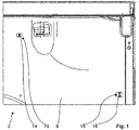
- the household appliance is designed as a tumble dryer and comprises a housing 2 with a housing cover 4, a housing front wall 6, a housing rear wall 8 and two housing side walls (not shown), a control panel 10 arranged on the housing front wall 6, a housing opening 11 arranged on the housing front wall 6, a Guide 12 arranged in housing 2 and fastened to housing 2, and a component that can be pushed into housing 2 with a gripping device arranged on the component for handling the component, the component being transferred into an insertion position of the component by means of housing opening 11 and of the guide 12 can be partially pushed into the housing 2, and the housing 2 has a width extending in the Y direction, a depth extending in the X direction and a height extending in the Z direction.
- a control panel 10 arranged on the housing front wall 6, a housing opening 11 arranged on the housing front wall 6, a Guide 12 arranged in housing 2 and fastened to housing 2, and a component that can be pushed into housing 2 with a gripping device arranged on the component for handling the component, the component
- the component with the gripping device arranged thereon is designed as a water container and is inserted into the Figures 1 to 6 not shown.
- the gripping device is arranged as a separate component on the component, that is to say the water container.
- the outer shape of the gripping device is designed as a grip plate, the grip plate and the control panel 10 being designed to be matched to one another in such a way that the grip plate optically essentially forms a unit with the control panel 10 in the insertion position of the component.
- the contours of the grip plate and the control panel 10 merge into one another in such a way that the grip plate looks like an integral part of the control panel 10.
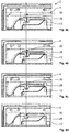
- An attachment of the guide 12 is formed on the housing 2 in such a way that the guide 12 when the household appliance is transferred into one in the Figure 4d partially shown assembly state of the household appliance in one in the Fig. 1 illustrated first assembly step floating on the housing rear wall 8 can be stored in a time following the first assembly step and in the Fig. 2 illustrated second assembly step can be mounted floating on the housing front wall 6, in a time following the second assembly step and in the Fig. 3 illustrated third assembly step can be positioned relative to the control panel 10 and in a time following the third assembly step and in the Figures 4a to 4d
- the fourth assembly step illustrated can be positioned relative to the housing cover 4, the guide 12 being spatially fixed on the housing 2 after the fourth assembly step.
- the attachment of the guide 12 to the housing 2 is designed in such a way that the guide 12 can be mounted floatingly in the Y direction in the first assembly step on the housing rear wall 8, the guide 12 also being fixable in the Z direction.
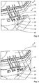
- the attachment of the guide 12 is designed in such a way that the guide 12 can be mounted floatingly in the XY direction in the second assembly step on the housing front wall 6, see FIG Fig. 2 ; that the guide 12 can be positioned in the third assembly step by means of the control panel 10 in the XY direction relative to the control panel 10, see Fig. 3 ; and that the guide 12 in the fourth assembly step by means of the housing cover 4 in the Y direction in a region of the housing rear wall 8 to which the housing cover 4 can be positioned.
- first bearing parts 14, 16 corresponding to one another are formed on the guide 12 and the housing rear wall 8, the first bearing parts 14, 16 being designed as pins 14 and pin receptacles 16.
- the guide 12 has two pegs 14 which, when the household appliance is in the assembled state, engage in a corresponding peg receptacle 16 in the rear wall 8 of the housing according to the first assembly step.
- corresponding second bearing parts 18, 19, 20, 21 are formed on the guide 12 and the housing front wall 6, with the second bearing parts 18, 20 as pins 18 and pin receptacles 20 and are designed as a rib 19 and rib receptacle 21.
- the guide 12 has a pin 18 and two ribs 19 which, when the household appliance is installed, engage in a corresponding pin receptacle 20 and rib receptacle 21 of the housing front wall 6 according to the second assembly step.
- corresponding third bearing parts 22, 24, 26 are formed on the guide 12, the housing front wall 6 and the control panel 10, with the third Bearing parts 22, 24, 26 are designed as centering pins 22, centering receptacle 24 and centering opening 26.
- the control panel 10 has the centering pin 22
- the guide 12 has the centering receptacle 24
- the front housing wall 6 has the centering opening 26, the centering pin 22 of the control panel 10 in the assembly state of the household appliance in the corresponding centering receptacle 24 of the guide 12 according to the third Assembly step intervenes.
- the centering opening 26 in the front housing wall 6 serves only to ensure that the centering pin 22 engaging in the centering receptacle 24 is not blocked in an undesired manner by the front housing wall 6.
- fourth bearing parts 28, 30 corresponding to one another are formed on the guide 12 and the housing cover 4, the fourth bearing parts 28 , 30 is designed as a centering projection 28 and a centering groove 30.
- the centering projection 28 is arranged on the guide 12 and the centering groove 30 is arranged on the housing cover 4.
- the household appliance is initially in a dismantled state.
- To transfer the household appliance to its assembled state proceed as follows:
- the guide 12 is floatingly mounted on the rear wall 8 of the housing.
- the two pins 14 arranged on the guide 12 are pushed into the corresponding pin receptacle 16 of the housing rear wall 8, so that the guide 12 is floatingly mounted on the housing rear wall 8 in the Y direction and is fixed in the Z direction. See the Fig. 1 .
- the guide 12 is then mounted in a floating manner on the front wall of the housing in a second assembly step that follows the first assembly step.
- the guide 12 is placed from above onto the housing front wall 6 in such a way that the pin 18 of the guide 12 into the corresponding pin receptacle 20 of the housing front wall 6 and the ribs 19 of the guide 12 into the respective corresponding rib receptacle 21 of the housing front wall 6, each with play in the XY direction, intervene.
- the guide 12 is floatingly mounted on the housing front wall 6 in the XY direction. Please refer Fig. 2 .
- the guide 12 is then positioned relative to the control panel 10 in a third assembly step that follows the second assembly step.
- the centering pin 22 arranged on the control panel 10 is inserted into the centering receptacle 24 of the guide 12 so that the centering pin 22 protrudes through the centering opening 26 of the housing front wall 6.
- the guide 12 is thereby positioned in the third assembly step by means of the control panel 10 in the XY direction to the control panel 10. Please refer Fig. 3 .
- the guide 12 is positioned relative to the housing cover 4 in the Y direction, the guide 12 being spatially fixed on the housing 2 after the fourth assembly step.
- the centering projection 28 of the guide 12 is brought into engagement with the centering groove 30 arranged on the housing cover 4.
- the housing cover 4 as in the Figures 4a to 4d shown, namely in the order Figure 4a , then 4b, then 4c and then 4d, pushed over the guide 12 held on the housing front wall 6 and on the housing rear wall 8 in the manner explained above.
- the centering groove 30 and designed as insertion bevels ensure that the guide 12 automatically aligns itself in the desired manner relative to the housing cover 4 when the housing cover 4 moves in the direction of the guide 12 by means of the centering projection 28 and the centering groove 30.
- the housing cover 4, the control panel 10 and the guide 12 in the household appliance in its assembled state are aligned with one another in the desired manner, that is to say positioned, so that an improved alignment, that is to say, the positioning in the guide 12 guided component is achieved relative to the control panel 10 and the housing cover 4.
- the gap images and gap dimensions between the housing cover 4, the control panel 10 and the guide 12 on a front side of the household appliance which are very important for the overall visual impression of a household appliance, are made possible in a predetermined manner in the present embodiment of the household appliance according to the invention and the method according to the invention. This is possible without a great deal of technical effort and thus saves work, material and costs. Accordingly, by means of the invention according to the present exemplary embodiment, a good gap pattern with only small gap dimensions is made possible in a structurally and technically simple manner.
- the invention is not limited to the present embodiment.
- the household appliance according to the invention and the method according to the invention for converting it into the installed state of the household appliance can also be used advantageously in other household appliances.
- the components of the household appliance can be freely selected within wide suitable limits in terms of material, dimensioning, shape and arrangement and are not limited to the specific structural design in the present exemplary embodiment. Accordingly, the individual assembly steps and the design of the bearing parts used can be adapted to the respective individual case.
- the arrangement of the individual bearing parts that correspond to one another is reversible in contrast to the present exemplary embodiment, so that, for example, a first bearing part designed as a pin can be arranged on the rear wall of the housing and a first bearing part designed as a pin receptacle can be arranged on the guide.
- a first bearing part designed as a pin can be arranged on the rear wall of the housing and a first bearing part designed as a pin receptacle can be arranged on the guide.
- the second, third and fourth bearing parts the number of the bearing parts is not limited to the number in the present embodiment.
- the individual bearing parts can be designed as an integral part of the respective component of the household appliance as well as a separate component, which can be and is connected to the corresponding component of the household appliance in a manner known to the person skilled in the art.
Abstract
Die Erfindung betrifft ein Haushaltsgerät, umfassend ein Gehäuse (2) und eine in das Gehäuse (2) einschiebbare Komponente, wobei die Komponente bei deren Überführung in eine Einschublage der Komponente mittels einer Gehäuseöffnung und einer Führung (12) in das Gehäuse (2) teilweise einschiebbar ist, und wobei das Gehäuse (2) eine in Y-Richtung verlaufende Breite, eine in X-Richtung verlaufende Tiefe und eine in Z-Richtung verlaufende Höhe aufweist.Eine Befestigung der Führung (12) ist an dem Gehäuse (2) derart ausgebildet, dass die Führung (12) bei einer Überführung des Haushaltsgeräts in einen Montagezustand des Haushaltsgeräts in einem ersten Montageschritt schwimmend an einer Gehäuserückwand (8) lagerbar ist, in einem auf den ersten Montageschritt zeitlich folgenden zweiten Montageschritt schwimmend an einer Gehäusevorderwand (6) lagerbar ist, in einem auf den zweiten Montageschritt zeitlich folgenden dritten Montageschritt relativ zu einer Bedienblende (10) positionierbar ist und in einem auf den dritten Montageschritt zeitlich folgenden vierten Montageschritt relativ zu einem Gehäusedeckel (4) positionierbar ist, wobei die Führung (12) zeitlich nach dem vierten Montageschritt an dem Gehäuse (2) räumlich festgelegt ist.Ferner betrifft die Erfindung ein Verfahren zur Überführung eines Haushaltsgeräts in einen Montagezustand.The invention relates to a household appliance, comprising a housing (2) and a component that can be pushed into the housing (2), the component being partially inserted into the housing (2) by means of a housing opening and a guide (12) when it is transferred into an insertion position of the component can be pushed in, and the housing (2) has a width running in the Y direction, a depth running in the X direction and a height running in the Z direction. The guide (12) is fastened to the housing (2) in this way designed so that the guide (12) can be mounted floating on a housing rear wall (8) in a first assembly step when the household appliance is transferred to an assembled state of the household appliance, and can be mounted floating on a front housing wall (6) in a second assembly step following the first assembly step is, can be positioned relative to a control panel (10) in a third assembly step that follows the second assembly step and i n a fourth assembly step following the third assembly step can be positioned relative to a housing cover (4), the guide (12) being spatially fixed after the fourth assembly step on the housing (2). Furthermore, the invention relates to a method for transferring a Household appliance in an assembly state.
Description
Die Erfindung betrifft ein Haushaltsgerät der im Oberbegriff des Patentanspruchs 1 genannten Art und ein Verfahren zur Überführung eines Haushaltsgeräts in einen Montagezustand der im Oberbegriff des Patentanspruchs 10 genannten Art.The invention relates to a household appliance of the type mentioned in the preamble of claim 1 and a method for converting a household appliance into an assembly state of the type mentioned in the preamble of
Derartige Haushaltsgeräte und Verfahren zur Überführung in deren Montagezustand sind aus dem Stand der Technik in einer Vielzahl von verschiedenen Ausführungsformen bereits bekannt. Die bekannten Haushaltsgeräte umfassen ein Gehäuse mit einem Gehäusedeckel, einer Gehäusevorderwand, einer Gehäuserückwand und zwei Gehäuseseitenwänden, eine an der Gehäusevorderwand angeordnete Bedienblende, eine an der Gehäusevorderwand angeordnete Gehäuseöffnung, eine in dem Gehäuse angeordnete und an dem Gehäuse befestigte Führung, und eine in das Gehäuse einschiebbare Komponente mit einer an der Komponente angeordneten Greifvorrichtung zur Handhabung der Komponente, wobei die Komponente bei deren Überführung in eine Einschublage der Komponente mittels der Gehäuseöffnung und der Führung in das Gehäuse teilweise einschiebbar ist, und wobei das Gehäuse eine in Y-Richtung verlaufende Breite, eine in X-Richtung verlaufende Tiefe und eine in Z-Richtung verlaufende Höhe aufweist.Such household appliances and methods for converting them into their assembled state are already known from the prior art in a large number of different embodiments. The known household appliances comprise a housing with a housing cover, a housing front wall, a housing rear wall and two housing side walls, a control panel arranged on the housing front wall, a housing opening arranged on the housing front wall, a guide arranged in the housing and attached to the housing, and one in the housing Insertable component with a gripping device arranged on the component for handling the component, the component being partially insertable into the housing when it is transferred into an insertion position of the component by means of the housing opening and the guide, and the housing having a width running in the Y direction, has a depth extending in the X direction and a height extending in the Z direction.
Der Erfindung stellt sich somit das Problem, ein Haushaltsgerät und ein Verfahren zur Überführung des Haushaltsgeräts in dessen Montagezustand zu verbessern.The invention thus poses the problem of improving a household appliance and a method for converting the household appliance into its assembled state.
Erfindungsgemäß wird dieses Problem durch ein Haushaltsgerät mit den Merkmalen des Patentanspruchs 1 gelöst, das dadurch gekennzeichnet ist, dass eine Befestigung der Führung an dem Gehäuse derart ausgebildet ist, dass die Führung bei einer Überführung des Haushaltsgeräts in einen Montagezustand des Haushaltsgeräts in einem ersten Montageschritt schwimmend an der Gehäuserückwand lagerbar ist, in einem auf den ersten Montageschritt zeitlich folgenden zweiten Montageschritt schwimmend an der Gehäusevorderwand lagerbar ist, in einem auf den zweiten Montageschritt zeitlich folgenden dritten Montageschritt relativ zu der Bedienblende positionierbar ist und in einem auf den dritten Montageschritt zeitlich folgenden vierten Montageschritt relativ zu dem Gehäusedeckel positionierbar ist, wobei die Führung zeitlich nach dem vierten Montageschritt an dem Gehäuse räumlich festgelegt ist. Ferner wird dieses Problem durch ein Verfahren mit den Merkmalen des Patentanspruchs 10 gelöst. Vorteilhafte Ausgestaltungen und Weiterbildungen der Erfindung ergeben sich aus den nachfolgenden Unteransprüchen.According to the invention, this problem is solved by a household appliance with the features of claim 1, which is characterized in that the guide is fastened to the housing in such a way that the guide is floating in a first assembly step when the household appliance is transferred to an assembled state of the household appliance can be stored on the rear wall of the housing, can be stored floating on the front wall of the housing in a second assembly step following the first assembly step, can be positioned relative to the control panel in a third assembly step following the second assembly step and in a fourth assembly step that follows the third assembly step can be positioned relative to the housing cover, the guide being spatially fixed on the housing after the fourth assembly step. Furthermore, this problem is solved by a method having the features of
Der mit der Erfindung erreichbare Vorteil besteht insbesondere darin, dass ein Haushaltsgerät und ein Verfahren zur Überführung des Haushaltsgeräts in dessen Montagezustand verbessert sind. Aufgrund der Erfindung ist eine verbesserte Ausrichtung, also Positionierung, der Führung und damit der in der Führung geführten Komponente relativ zu der Bedienblende und zu dem Gehäusedeckel ermöglicht. Für den optischen Gesamteindruck eines Haushaltsgeräts ist insbesondere die Frontansicht des Haushaltsgeräts und dabei der Bereich der Bedienblende von entscheidender Bedeutung. Für einen guten optischen Eindruck sind vor allem die Spalte zwischen dem Gehäusedeckel, der Bedienblende und der in der Einschublage befindlichen Komponente mit der daran angeordneten Greifvorrichtung wichtig. Bislang ist die Einhaltung von möglichst kleinen Spaltabmessungen und einem möglichst gleichmäßigen Spaltbild lediglich mit einem großen technischen Aufwand und damit arbeits-, material- und kostenintensiv möglich. Die Erfindung schafft hier Abhilfe, so dass mittels der Erfindung ein gutes Spaltbild mit lediglich geringen Spaltabmessungen auf konstruktiv und fertigungstechnisch einfache Weise ermöglicht ist.The advantage that can be achieved with the invention is, in particular, that a household appliance and a method for converting the household appliance into its assembled state are improved. Due to the invention, an improved alignment, that is, positioning, of the guide and thus of the component guided in the guide relative to the control panel and to the housing cover is made possible. For the overall visual impression of a household appliance, in particular the front view of the household appliance and thereby the area of the control panel are of decisive importance. For a good visual impression, the gaps between the housing cover, the control panel and the component located in the insertion position with the gripping device arranged thereon are particularly important. Up to now, maintaining the smallest possible gap dimensions and a gap pattern that is as uniform as possible has only been possible with a great deal of technical effort and thus labor, material and cost intensive. The invention provides a remedy here, so that by means of the invention a good gap pattern with only small gap dimensions is made possible in a structurally and technically simple manner.
Das Haushaltsgerät kann beispielsweise als eine Wäschebehandlungsmaschine, wie eine Waschmaschine, ein Wäschetrockner oder ein Waschtrockner ausgebildet sein. Die Komponente kann dabei beispielsweise als ein Einspülkasten oder ein Wasserkasten ausgebildet sein. Die Greifvorrichtung kann an der Komponente ausgebildet oder an dieser als ein separates Bauteil angeordnet sein. Die Greifvorrichtung kann in deren äußerer Form beispielsweise als eine Griffplatte ausgebildet sein. Entsprechend können die Griffplatte und die Bedienblende derart aufeinander abgestimmt ausgebildet sein, dass die Griffplatte in der Einschublage der Komponente mit der Bedienblende optisch im Wesentlichen eine Einheit bildet. Diese Aufzählung ist jedoch rein exemplarisch.The household appliance can be designed, for example, as a laundry treatment machine, such as a washing machine, a tumble dryer or a washer-dryer. The component can be designed, for example, as a dispenser or a water tank. The gripping device can be formed on the component or arranged on it as a separate component. The outer shape of the gripping device can be designed, for example, as a grip plate. Correspondingly, the grip plate and the control panel can be designed to be coordinated with one another in such a way that the grip plate optically essentially forms a unit with the control panel in the insertion position of the component. However, this list is purely exemplary.
Eine vorteilhafte Weiterbildung des erfindungsgemäßen Haushaltsgeräts sieht vor, dass die Befestigung der Führung an dem Gehäuse derart ausgebildet ist, dass die Führung in dem ersten Montageschritt an der Gehäuserückwand in Y-Richtung schwimmend lagerbar ist, bevorzugt, dass die Führung zusätzlich in Z-Richtung fixierbar ist. Hierdurch ist die Überführung des Haushaltsgeräts in dessen Montagezustand wesentlich erleichtert, da die Führung mittels der Gehäuserückwand zunächst in einer Art Parkposition gehalten ist. Die bevorzugte Ausführungsform dieser Weiterbildung weist den zusätzlichen Vorteil auf, dass die Führung in einem Bereich der Rückwand in Z-Richtung fixierbar ist.An advantageous development of the household appliance according to the invention provides that the attachment of the guide to the housing is designed in such a way that the guide can be mounted floating in the Y direction in the first assembly step on the rear wall of the housing, preferably that the guide can also be fixed in the Z direction is. This makes it much easier to transfer the household appliance to its assembled state, since the guide is initially held in a kind of parking position by means of the rear wall of the housing. The preferred embodiment of this development has the additional advantage that the guide can be fixed in a region of the rear wall in the Z direction.
Entsprechend sieht eine vorteilhafte Weiterbildung des erfindungsgemäßen Verfahrens vor, dass die Führung in dem ersten Montageschritt an der Gehäuserückwand in Y-Richtung schwimmend gelagert wird, bevorzugt, dass die Führung zusätzlich in Z-Richtung fixiert wird.Correspondingly, an advantageous further development of the method according to the invention provides that the guide is mounted floatingly on the rear wall of the housing in the Y direction in the first assembly step, preferably that the guide is additionally fixed in the Z direction.
Eine weitere vorteilhafte Weiterbildung des erfindungsgemäßen Haushaltsgeräts sieht vor, dass die Befestigung der Führung an dem Gehäuse derart ausgebildet ist, dass die Führung in dem zweiten Montageschritt an der Gehäusevorderwand in X-Y-Richtung schwimmend lagerbar ist. Auf diese Weise ist, in Vorbereitung auf den dritten Montageschritt, eine Vorjustierung der Führung relativ zu der Gehäusevorderwand in X-Y-Richtung, also in X-Richtung schwimmend und in Y-Richtung schwimmend, ermöglicht.Another advantageous development of the household appliance according to the invention provides that the attachment of the guide to the housing is designed in such a way that the guide can be mounted floating in the XY direction on the housing front wall in the second assembly step. In this way, in preparation for the third assembly step, a pre-adjustment of the guide relative to the housing front wall in the XY direction, that is to say floating in the X direction and floating in the Y direction, is made possible.
Entsprechend sieht eine vorteilhafte Weiterbildung des erfindungsgemäßen Verfahrens vor, dass die Führung in dem zweiten Montageschritt an der Gehäusevorderwand in X-Y-Richtung schwimmend gelagert wird.Correspondingly, an advantageous development of the method according to the invention provides that the guide is mounted in a floating manner in the X-Y direction on the housing front wall in the second assembly step.
Eine andere vorteilhafte Weiterbildung des erfindungsgemäßen Haushaltsgeräts sieht vor, dass die Befestigung der Führung an dem Gehäuse derart ausgebildet ist, dass die Führung in dem dritten Montageschritt mittels der Bedienblende in X-Y-Richtung zu der Bedienblende positionierbar ist. Hierdurch ist eine endgültige Positionierung, also Ausrichtung, der Führung relativ zu der Bedienblende in X-Y-Richtung mittels der Bedienblende selbst ermöglicht.Another advantageous development of the household appliance according to the invention provides that the attachment of the guide to the housing is designed in such a way that the guide can be positioned in the third assembly step by means of the control panel in the X-Y direction relative to the control panel. This enables final positioning, that is to say alignment, of the guide relative to the control panel in the X-Y direction by means of the control panel itself.
Entsprechend sieht eine vorteilhafte Weiterbildung des erfindungsgemäßen Verfahrens vor, dass die Führung in dem dritten Montageschritt mittels der Bedienblende in X-Y-Richtung zu der Bedienblende positioniert wird.Correspondingly, an advantageous development of the method according to the invention provides that the guide is positioned in the third assembly step by means of the control panel in the X-Y direction relative to the control panel.
Eine weitere vorteilhafte Weiterbildung des erfindungsgemäßen Haushaltsgeräts sieht vor, dass die Befestigung der Führung an dem Gehäuse derart ausgebildet ist, dass die Führung in dem vierten Montageschritt mittels des Gehäusedeckels in Y-Richtung, bevorzugt in einem Bereich der Gehäuserückwand, zu dem Gehäusedeckel positionierbar ist. Auf diese Weise ist eine endgültige Positionierung, also Ausrichtung, der Führung relativ zu dem Gehäusedeckel in Y-Richtung mittels des Gehäusedeckels selbst ermöglicht. Die bevorzugte Ausführungsform dieser Weiterbildung hat darüber hinaus den weiteren Vorteil, dass die Positionierung der Führung relativ zu dem Gehäusedeckel gemäß dem vierten Montageschritt aufgrund einer gewissen Flexibilität der Führung in Y-Richtung entlang der Ausdehnung der Führung in X-Richtung, trotz der Positionierung der Führung relativ zu der Bedienblende gemäß dem dritten Montageschritt, leicht möglich ist.Another advantageous development of the household appliance according to the invention provides that the attachment of the guide to the housing is designed in such a way that the guide can be positioned relative to the housing cover in the fourth assembly step by means of the housing cover in the Y direction, preferably in an area of the housing rear wall. In this way, a final positioning, that is to say alignment, of the guide relative to the housing cover in the Y direction is made possible by means of the housing cover itself. The preferred embodiment of this development also has the further advantage that the positioning of the guide relative to the housing cover according to the fourth assembly step due to a certain flexibility of the guide in the Y direction along the extension of the guide in the X direction, despite the positioning of the guide relative to the control panel according to the third assembly step, is easily possible.
Entsprechend sieht eine vorteilhafte Weiterbildung des erfindungsgemäßen Verfahrens vor, dass die Führung in dem vierten Montageschritt mittels des Gehäusedeckels in Y-Richtung, bevorzugt in einem Bereich der Gehäuserückwand, zu dem Gehäusedeckel positioniert wird.Accordingly, an advantageous development of the method according to the invention provides that the guide is positioned in the fourth assembly step by means of the housing cover in the Y direction, preferably in a region of the housing rear wall, relative to the housing cover.
Eine andere vorteilhafte Weiterbildung des erfindungsgemäßen Haushaltsgeräts sieht vor, dass zur Durchführung des ersten Montageschritts an der Führung und der Gehäuserückwand zueinander korrespondierende erste Lagerteile ausgebildet sind, wobei die ersten Lagerteile bevorzugt als Zapfen und Zapfenaufnahme ausgebildet sind. Hierdurch ist die Verbindung der Führung mit der Gehäuserückwand gemäß dem ersten Montageschritt auf konstruktiv einfache und robuste Weise herstellbar. Insbesondere gilt dies für die bevorzugte Ausführungsform dieser Weiterbildung. Ferner ist es denkbar, dass der Zapfen und die zu dem Zapfen korrespondierende Zapfenaufnahme Einführhilfen, wie beispielsweise Einführschrägen oder dergleichen, zur leichteren Durchführung des ersten Montageschritts aufweisen.Another advantageous development of the household appliance according to the invention provides that first bearing parts corresponding to one another are formed in order to carry out the first assembly step on the guide and the rear wall of the housing, the first bearing parts preferably being formed as a pin and pin receptacle. This enables the connection of the guide to the rear wall of the housing according to the first assembly step can be produced in a structurally simple and robust manner. This applies in particular to the preferred embodiment of this development. Furthermore, it is conceivable that the pin and the pin receptacle corresponding to the pin have insertion aids, such as insertion bevels or the like, for easier implementation of the first assembly step.
Eine weitere vorteilhafte Weiterbildung des erfindungsgemäßen Haushaltsgeräts sieht vor, dass zur Durchführung des zweiten Montageschritts an der Führung und der Gehäusevorderwand zueinander korrespondierende zweite Lagerteile ausgebildet sind, wobei die zweiten Lagerteile bevorzugt als Zapfen und Zapfenaufnahme und/oder als Rippe und Rippenaufnahme ausgebildet sind. Auf diese Weise ist die Halterung der Führung an der Gehäusevorderwand gemäß dem zweiten Montageschritt ebenfalls auf konstruktiv einfache und robuste Weise herstellbar. Wiederum gilt dies insbesondere für die bevorzugte Ausführungsform dieser Weiterbildung. Darüber hinaus ist es denkbar, dass der Zapfen und die zu dem Zapfen korrespondierende Zapfenaufnahme und/oder die Rippe und die zu der Rippe korrespondierende Rippenaufnahme Einführhilfen, wie beispielsweise Einführschrägen oder dergleichen, zur leichteren Durchführung des zweiten Montageschritts aufweisen.A further advantageous development of the household appliance according to the invention provides that to carry out the second assembly step on the guide and the housing front wall corresponding second bearing parts are formed, the second bearing parts preferably being designed as a pin and pin receptacle and / or as a rib and rib receptacle. In this way, the mounting of the guide on the housing front wall according to the second assembly step can also be produced in a structurally simple and robust manner. Again, this applies in particular to the preferred embodiment of this development. In addition, it is conceivable that the pin and the pin receptacle corresponding to the pin and / or the rib and the rib receptacle corresponding to the rib have insertion aids, such as insertion bevels or the like, for easier implementation of the second assembly step.
Eine andere vorteilhafte Weiterbildung des erfindungsgemäßen Haushaltsgeräts sieht vor, dass zur Durchführung des dritten Montageschritts an der Führung, der Gehäusevorderwand und der Bedienblende zueinander korrespondierende dritte Lagerteile ausgebildet sind, wobei die dritten Lagerteile bevorzugt als Zentrierzapfen, Zentrieröffnung und Zentrieraufnahme ausgebildet sind. Hierdurch ist die Positionierung der Führung zu der Bedienblende gemäß dem dritten Montageschritt auf konstruktiv einfache und robuste Weise herstellbar. Insbesondere gilt dies für die bevorzugte Ausführungsform dieser Weiterbildung. Darüber hinaus ist es denkbar, dass der Zentrierzapfen und die zu dem Zentrierzapfen korrespondierende Zentrieröffnung und Zapfenaufnahme Einführhilfen, wie beispielsweise Einführschrägen oder dergleichen, zur leichteren Durchführung des dritten Montageschritts aufweisen.Another advantageous development of the household appliance according to the invention provides that to carry out the third assembly step on the guide, the housing front wall and the control panel, corresponding third bearing parts are formed, the third bearing parts preferably being designed as centering pins, centering opening and centering receptacle. As a result, the positioning of the guide to the control panel according to the third assembly step can be produced in a structurally simple and robust manner. This applies in particular to the preferred embodiment of this development. In addition, it is conceivable that the centering pin and the centering opening and pin receptacle corresponding to the centering pin have insertion aids, such as insertion bevels or the like, for easier implementation of the third assembly step.
Eine weitere vorteilhafte Weiterbildung des erfindungsgemäßen Haushaltsgeräts sieht vor, dass zur Durchführung des vierten Montageschritts an der Führung und dem Gehäusedeckel zueinander korrespondierende vierte Lagerteile ausgebildet sind, wobei die vierten Lagerteile bevorzugt als Zentriervorsprung und Zentriernut ausgebildet sind. Auf diese Weise ist die Positionierung der Führung zu dem Gehäusedeckel gemäß dem vierten Montageschritt ebenfalls auf konstruktiv einfache und robuste Weise herstellbar. Vor allem gilt dies für die bevorzugte Ausführungsform dieser Weiterbildung. Darüber hinaus ist es denkbar, dass der Zentriervorsprung und die zu dem Zentriervorsprung korrespondierende Zentriernut Einführhilfen, wie beispielsweise Einführschrägen oder dergleichen, zur leichteren Durchführung des vierten Montageschritts aufweisen.Another advantageous development of the household appliance according to the invention provides that corresponding fourth bearing parts are formed on the guide and the housing cover to carry out the fourth assembly step, the fourth bearing parts preferably being formed as a centering projection and centering groove. In this way, the positioning of the guide to the housing cover according to the fourth assembly step can also be produced in a structurally simple and robust manner. This applies above all to the preferred embodiment of this development. In addition, it is conceivable that the centering projection and the centering groove corresponding to the centering projection Have insertion aids, such as insertion bevels or the like, for easier implementation of the fourth assembly step.
Ein Ausführungsbeispiel der Erfindung ist in den Zeichnungen rein schematisch dargestellt und wird nachfolgend näher beschrieben. Es zeigt
- Figur 1
- ein Ausführungsbeispiel des erfindungsgemäßen Haushaltsgeräts in einer teilweisen Darstellung mit Blick von außen auf die Gehäuserückwand,
Figur 2- das Ausführungsbeispiel in einer ersten teilweisen, perspektivischen Darstellung mit Blick von innen auf die Gehäusevorderwand,
- Figur 3
- das Ausführungsbeispiel in einer zweiten teilweisen, perspektivischen Darstellung mit Blick von innen auf die Gehäusevorderwand,
- Figur 4a
- das Ausführungsbeispiel in einer teilweisen, geschnittenen Draufsicht auf den Gehäusedeckel mit Blick auf die Führung in einer ersten Lage des Gehäusedeckels,
- Figur 4b
- das Ausführungsbeispiel in einer teilweisen, geschnittenen Draufsicht auf den Gehäusedeckel mit Blick auf die Führung in einer zweiten Lage des Gehäusedeckels,
- Figur 4c
- das Ausführungsbeispiel in einer teilweisen, geschnittenen Draufsicht auf den Gehäusedeckel mit Blick auf die Führung in einer dritten Lage des Gehäusedeckels,
- Figur 4d
- das Ausführungsbeispiel in einer teilweisen, geschnittenen Draufsicht auf den Gehäusedeckel mit Blick auf die Führung in einer vierten Lage des Gehäusedeckels,
- Figur 5
- die Führung des Ausführungsbeispiels in einer teilweisen, perspektivischen Darstellung mit Blick von oben auf die Führung und
Figur 6- den Gehäusedeckel des Ausführungsbeispiels in einer teilweisen, perspektivischen Darstellung mit Blick von unten auf den Gehäusedeckel.
- Figure 1
- an embodiment of the household appliance according to the invention in a partial representation with a view from the outside of the rear wall of the housing,
- Figure 2
- the embodiment in a first partial, perspective view with a view from the inside of the housing front wall,
- Figure 3
- the embodiment in a second partial, perspective view with a view from the inside of the housing front wall,
- Figure 4a
- the exemplary embodiment in a partial, sectional top view of the housing cover with a view of the guide in a first position of the housing cover,
- Figure 4b
- the exemplary embodiment in a partial, sectional top view of the housing cover with a view of the guide in a second layer of the housing cover,
- Figure 4c
- the exemplary embodiment in a partial, sectional top view of the housing cover with a view of the guide in a third layer of the housing cover,
- Figure 4d
- the exemplary embodiment in a partial, sectional top view of the housing cover with a view of the guide in a fourth position of the housing cover,
- Figure 5
- the leadership of the embodiment in a partial, perspective view with a view from above of the leadership and
- Figure 6
- the housing cover of the embodiment in a partial, perspective view with a view of the housing cover from below.
In den
Das Haushaltsgerät ist als ein Wäschetrockner ausgebildet und umfasst ein Gehäuse 2 mit einem Gehäusedeckel 4, einer Gehäusevorderwand 6, einer Gehäuserückwand 8 und zwei nicht dargestellten Gehäuseseitenwänden, eine an der Gehäusevorderwand 6 angeordnete Bedienblende 10, eine an der Gehäusevorderwand 6 angeordnete Gehäuseöffnung 11, eine in dem Gehäuse 2 angeordnete und an dem Gehäuse 2 befestigte Führung 12, und eine in das Gehäuse 2 einschiebbare Komponente mit einer an der Komponente angeordneten Greifvorrichtung zur Handhabung der Komponente, wobei die Komponente bei deren Überführung in eine Einschublage der Komponente mittels der Gehäuseöffnung 11 und der Führung 12 in das Gehäuse 2 teilweise einschiebbar ist, und wobei das Gehäuse 2 eine in Y-Richtung verlaufende Breite, eine in X-Richtung verlaufende Tiefe und eine in Z-Richtung verlaufende Höhe aufweist. In der Bildebene von der
Eine Befestigung der Führung 12 ist an dem Gehäuse 2 derart ausgebildet, dass die Führung 12 bei einer Überführung des Haushaltsgeräts in einen in der
Die Befestigung der Führung 12 an dem Gehäuse 2 ist dabei derart ausgebildet, dass die Führung 12 in dem ersten Montageschritt an der Gehäuserückwand 8 in Y-Richtung schwimmend lagerbar ist, wobei die Führung 12 zusätzlich in Z-Richtung fixierbar ist. Siehe
Zwecks schwimmender Lagerung der Führung 12 an der Gehäuserückwand 8 in Y-Richtung sind an der Führung 12 und der Gehäuserückwand 8 zueinander korrespondierende erste Lagerteile 14, 16 ausgebildet, wobei die ersten Lagerteile 14, 16 als Zapfen 14 und Zapfenaufnahme 16 ausgebildet sind. Bei dem vorliegenden Ausführungsbeispiel weist die Führung 12 zwei Zapfen 14 auf, die in dem Montagezustand des Haushaltsgeräts in jeweils eine korrespondierende Zapfenaufnahme 16 der Gehäuserückwand 8 gemäß dem ersten Montageschritt eingreifen.For the purpose of floating support of the
Um die Führung 12 an der Gehäusevorderwand 6 in X-Y-Richtung schwimmend zu lagern, sind an der Führung 12 und der Gehäusevorderwand 6 zueinander korrespondierende zweite Lagerteile 18, 19, 20, 21 ausgebildet, wobei die zweiten Lagerteile 18, 20 als Zapfen 18 und Zapfenaufnahme 20 und als Rippe 19 und Rippenaufnahme 21 ausgebildet sind. Bei dem vorliegenden Ausführungsbeispiel weist die Führung 12 einen Zapfen 18 und zwei Rippen 19 auf, die in dem Montagezustand des Haushaltsgeräts in jeweils eine korrespondierende Zapfenaufnahme 20 und Rippenaufnahme 21 der Gehäusevorderwand 6 gemäß dem zweiten Montageschritt eingreifen.In order to mount the
Um die Führung 12 in dem dritten Montageschritt mittels der Bedienblende 10 in X-Y-Richtung zu der Bedienblende 10 zu positionieren, sind an der Führung 12, der Gehäusevorderwand 6 und der Bedienblende 10 zueinander korrespondierende dritte Lagerteile 22, 24, 26 ausgebildet, wobei die dritten Lagerteile 22, 24, 26 als Zentrierzapfen 22, Zentrieraufnahme 24 und Zentrieröffnung 26 ausgebildet sind. Bei dem vorliegenden Ausführungsbeispiel weist die Bedienblende 10 den Zentrierzapfen 22, die Führung 12 die Zentrieraufnahme 24 und die Gehäusevorderwand 6 die Zentrieröffnung 26 auf, wobei der Zentrierzapfen 22 der Bedienblende 10 in dem Montagezustand des Haushaltsgeräts in die korrespondierende Zentrieraufnahme 24 der Führung 12 gemäß dem dritten Montageschritt eingreift. Die Zentrieröffnung 26 der Gehäusevorderwand 6 dient lediglich dazu, dass der in die Zentrieraufnahme 24 eingreifende Zentrierzapfen 22 nicht in ungewünschter Weise durch die Gehäusevorderwand 6 blockiert wird.In order to position the
Zwecks Positionierung der Führung 12 mittels des Gehäusedeckels 4 in Y-Richtung relativ zu dem Gehäusedeckel 4, nämlich in einem Bereich der Gehäuserückwand 8, sind an der Führung 12 und dem Gehäusedeckel 4 zueinander korrespondierende vierte Lagerteile 28, 30 ausgebildet, wobei die vierten Lagerteile 28, 30 als Zentriervorsprung 28 und Zentriernut 30 ausgebildet. Bei dem vorliegenden Ausführungsbeispiel ist der Zentriervorsprung 28 an der Führung 12 und die Zentriernut 30 an dem Gehäusedeckel 4 angeordnet.For the purpose of positioning the
Nachfolgend wird die Funktionsweise des erfindungsgemäßen Haushaltsgeräts bei dessen Überführung in den Montagezustand des Haushaltsgeräts sowie das erfindungsgemäße Verfahren gemäß dem vorliegenden Ausführungsbeispiel anhand der
Das Haushaltsgerät befindet sich zunächst in einem Demontagezustand. Zwecks Überführung des Haushaltsgeräts in dessen Montagezustand wird wie folgt vorgegangen:
Die Führung 12 wird in einem ersten Montageschritt schwimmend an der Gehäuserückwand 8 gelagert. Hierzu werden die beiden an der Führung 12 angeordneten Zapfen 14 in die jeweils korrespondierende Zapfenaufnahme 16 der Gehäuserückwand 8 eingeschoben, so dass die Führung 12 zum einen an der Gehäuserückwand 8 in Y-Richtung schwimmend gelagert ist und zum anderen in Z-Richtung fixiert ist. Siehe die
In a first assembly step, the
Anschließend wird die Führung 12 in einem auf den ersten Montageschritt zeitlich folgenden zweiten Montageschritt schwimmend an der Gehäusevorderwand gelagert. Hierfür wird die Führung 12 derart von oben auf die Gehäusevorderwand 6 aufgelegt, dass der Zapfen 18 der Führung 12 in die dazu korrespondierende Zapfenaufnahme 20 der Gehäusevorderwand 6 und die Rippen 19 der Führung 12 in die jeweils korrespondierende Rippenaufnahme 21 der Gehäusevorderwand 6, jeweils mit Spiel in X-Y-Richtung, eingreifen. Somit ist die Führung 12 gemäß dem zweiten Montageschritt an der Gehäusevorderwand 6 in X-Y-Richtung schwimmend gelagert. Siehe
Danach wird die Führung 12 in einem auf den zweiten Montageschritt zeitlich folgenden dritten Montageschritt relativ zu der Bedienblende 10 positioniert. Hierzu wird der an der Bedienblende 10 angeordnete Zentrierzapfen 22 in die Zentrieraufnahme 24 der Führung 12 eingesteckt, so dass der Zentrierzapfen 22 durch die Zentrieröffnung 26 der Gehäusevorderwand 6 hindurchragt. Die Führung 12 ist hierdurch in dem dritten Montageschritt mittels der Bedienblende 10 in X-Y-Richtung zu der Bedienblende 10 positioniert. Siehe
Abschließend wird die Führung 12 in einem auf den dritten Montageschritt zeitlich folgenden vierten Montageschritt relativ zu dem Gehäusedeckel 4 in Y-Richtung positioniert, wobei die Führung 12 zeitlich nach dem vierten Montageschritt an dem Gehäuse 2 räumlich festgelegt ist. In dem vierten Montageschritt wird der Zentriervorsprung 28 der Führung 12 in Eingriff mit der an dem Gehäusedeckel 4 angeordneten Zentriernut 30 gebracht. Hierfür wird der Gehäusedeckel 4, wie in den
Bei dem vorliegenden Ausführungsbeispiel ist somit gewährleistet, dass der Gehäusedeckel 4, die Bedienblende 10 und die Führung 12 bei dem in dessen Montagezustand befindlichen Haushaltsgerät zueinander in gewünschter Weise ausgerichtet, also positioniert sind, so dass eine verbesserte Ausrichtung, also Positionierung, der in der Führung 12 geführten Komponente relativ zu der Bedienblende 10 und zu dem Gehäusedeckel 4 erzielt ist. Insbesondere die für den optischen Gesamteindruck eines Haushaltsgeräts sehr wichtigen Spaltbilder und Spaltabmessungen zwischen dem Gehäusedeckel 4, der Bedienblende 10 und der Führung 12 an einer Frontseite des Haushaltsgeräts sind bei dem vorliegenden Ausführungsbeispiel des erfindungsgemäßen Haushaltsgeräts sowie des erfindungsgemäßen Verfahrens in vorher festgelegter Weise wunschgemäß ermöglicht. Dies ist dabei ohne großen technischen Aufwand und damit arbeits-, material- und kostenschonend möglich. Entsprechend ist mittels der Erfindung gemäß dem vorliegenden Ausführungsbeispiel ein gutes Spaltbild mit lediglich geringen Spaltabmessungen auf konstruktiv und fertigungstechnisch einfache Weise ermöglicht.In the present exemplary embodiment, it is thus ensured that the
Die Erfindung ist nicht auf das vorliegende Ausführungsbeispiel begrenzt. Beispielsweise ist das erfindungsgemäße Haushaltsgerät und das erfindungsgemäße Verfahren zu dessen Überführung in den Montagezustand des Haushaltsgeräts auch bei anderen Haushaltsgeräten vorteilhaft einsetzbar. Die Bauteile des Haushaltsgeräts sind nach Material, Dimensionierung, Form und Anordnung in weiten geeigneten Grenzen frei wählbar und nicht auf die konkrete konstruktive Ausbildung bei dem vorliegenden Ausführungsbeispiel beschränkt. Entsprechend sind die einzelnen Montageschritte sowie die konstruktive Ausbildung der verwendeten Lagerteile auf den jeweiligen Einzelfall anpassbar.The invention is not limited to the present embodiment. For example, the household appliance according to the invention and the method according to the invention for converting it into the installed state of the household appliance can also be used advantageously in other household appliances. The components of the household appliance can be freely selected within wide suitable limits in terms of material, dimensioning, shape and arrangement and are not limited to the specific structural design in the present exemplary embodiment. Accordingly, the individual assembly steps and the design of the bearing parts used can be adapted to the respective individual case.
Beispielsweise ist die Anordnung der einzelnen zueinander korrespondierenden Lagerteile im Unterschied zu dem vorliegenden Ausführungsbeispiel umkehrbar, so dass beispielsweise ein als Zapfen ausgebildetes erstes Lagerteil an der Gehäuserückwand und ein als Zapfenaufnahme ausgebildetes erstes Lagerteil an der Führung angeordnet sein kann. Entsprechendes gilt für die zweiten, dritten und vierten Lagerteile. Auch ist die Anzahl der Lagerteile nicht auf die Anzahl bei dem vorliegenden Ausführungsbeispiel begrenzt. Die einzelnen Lagerteile können dabei als ein integraler Bestandteil des jeweiligen Bauteils des Haushaltsgeräts wie auch als ein davon separates Bauteil ausgebildet sein, welches mit dem entsprechenden Bauteil des Haushaltsgeräts auf dem Fachmann bekannte Weise verbindbar ist und verbunden wird.For example, the arrangement of the individual bearing parts that correspond to one another is reversible in contrast to the present exemplary embodiment, so that, for example, a first bearing part designed as a pin can be arranged on the rear wall of the housing and a first bearing part designed as a pin receptacle can be arranged on the guide. The same applies to the second, third and fourth bearing parts. Also, the number of the bearing parts is not limited to the number in the present embodiment. The individual bearing parts can be designed as an integral part of the respective component of the household appliance as well as a separate component, which can be and is connected to the corresponding component of the household appliance in a manner known to the person skilled in the art.
Claims (14)
Applications Claiming Priority (1)
| Application Number | Priority Date | Filing Date | Title |
|---|---|---|---|
| DE102020106905.7A DE102020106905A1 (en) | 2020-03-13 | 2020-03-13 | Household appliance and method for converting the household appliance into an assembly state |
Publications (1)
| Publication Number | Publication Date |
|---|---|
| EP3879025A1 true EP3879025A1 (en) | 2021-09-15 |
Family
ID=74673038
Family Applications (1)
| Application Number | Title | Priority Date | Filing Date |
|---|---|---|---|
| EP21158337.2A Pending EP3879025A1 (en) | 2020-03-13 | 2021-02-22 | Household appliance and method for transferring the household appliance to a mounting state |
Country Status (2)
| Country | Link |
|---|---|
| EP (1) | EP3879025A1 (en) |
| DE (1) | DE102020106905A1 (en) |
Citations (4)
| Publication number | Priority date | Publication date | Assignee | Title |
|---|---|---|---|---|
| CN101168905A (en) * | 2006-10-23 | 2008-04-30 | 南京乐金熊猫电器有限公司 | Top board arrangement structure for washing device |
| EP2458067A1 (en) * | 2010-11-29 | 2012-05-30 | Electrolux Home Products Corporation N.V. | Laundry dryer |
| EP2746446A1 (en) * | 2012-12-21 | 2014-06-25 | Electrolux Home Products Corporation N.V. | Support structure of a rotary drum laundry treating appliance and rotary drum laundry treating appliance including said support structure |
| EP2778278A2 (en) * | 2013-03-13 | 2014-09-17 | Miele & Cie. KG | Housing for household devices such as a laundry dryer, a washing machine, or the like |
Family Cites Families (2)
| Publication number | Priority date | Publication date | Assignee | Title |
|---|---|---|---|---|
| WO2016145717A1 (en) | 2015-03-13 | 2016-09-22 | 无锡小天鹅股份有限公司 | Detergent container assembly for washing machine, and washing machine having same |
| CN108315969B (en) | 2018-01-29 | 2020-10-23 | 无锡小天鹅电器有限公司 | Cartridge fixing structure and drum washing machine |
-
2020
- 2020-03-13 DE DE102020106905.7A patent/DE102020106905A1/en active Pending
-
2021
- 2021-02-22 EP EP21158337.2A patent/EP3879025A1/en active Pending
Patent Citations (4)
| Publication number | Priority date | Publication date | Assignee | Title |
|---|---|---|---|---|
| CN101168905A (en) * | 2006-10-23 | 2008-04-30 | 南京乐金熊猫电器有限公司 | Top board arrangement structure for washing device |
| EP2458067A1 (en) * | 2010-11-29 | 2012-05-30 | Electrolux Home Products Corporation N.V. | Laundry dryer |
| EP2746446A1 (en) * | 2012-12-21 | 2014-06-25 | Electrolux Home Products Corporation N.V. | Support structure of a rotary drum laundry treating appliance and rotary drum laundry treating appliance including said support structure |
| EP2778278A2 (en) * | 2013-03-13 | 2014-09-17 | Miele & Cie. KG | Housing for household devices such as a laundry dryer, a washing machine, or the like |
Also Published As
| Publication number | Publication date |
|---|---|
| DE102020106905A1 (en) | 2021-09-16 |
Similar Documents
| Publication | Publication Date | Title |
|---|---|---|
| DE102009006906B4 (en) | Vehicle seat with table | |
| DE60017464T2 (en) | CARRIER FRAME FOR A CONTROL CABINET | |
| DE60313461T2 (en) | CABINET FOR HOME APPLIANCE | |
| DE102010037534A1 (en) | Apparatus and method for producing at least partially closed hollow profiles with rotatable die halves and low cycle time | |
| DE102009058616A1 (en) | Printed circuit board connector with locking device | |
| DE112015001732B4 (en) | Connector with an alignment function | |
| DE112012006722T5 (en) | Connector cover and connector connection device | |
| DE102017118751A1 (en) | Locking device for a plug connection | |
| DE102017119057B3 (en) | System of two connector housings and a locking device | |
| WO2008080638A1 (en) | Arrangement having a dispensing compartment and a molded handle for a washing machine | |
| DE112014004656T5 (en) | Power supply device and method for assembling a power supply device | |
| DE112005001538B4 (en) | Control panel arrangement of a washing machine | |
| DE102021201485A1 (en) | Laundry treating device | |
| EP3879025A1 (en) | Household appliance and method for transferring the household appliance to a mounting state | |
| DE112012001900T5 (en) | Attachment structure for vehicle interior light | |
| EP1705282B1 (en) | Steam ironing board | |
| EP0421370B1 (en) | Force transducer for Jacquard machine | |
| DE112015005657T5 (en) | load input | |
| EP1880778B1 (en) | Method for punching holes for the handle of a mortice bolt into a window profile | |
| EP0254056B1 (en) | Longitudinally elongated racks with holding clamps for removably mounting circuit boards | |
| DE19518220B4 (en) | Extraction device for a telecommunication device frame | |
| DE202004004619U1 (en) | Mechanical locking device for electrical connector housings | |
| DE3130193A1 (en) | LIFTING DEVICE WITH ROLLERS | |
| DE112015006159T5 (en) | relay | |
| DE202018104468U1 (en) | Two-sided clamp with seal |
Legal Events
| Date | Code | Title | Description |
|---|---|---|---|
| PUAI | Public reference made under article 153(3) epc to a published international application that has entered the european phase |
Free format text: ORIGINAL CODE: 0009012 |
|
| STAA | Information on the status of an ep patent application or granted ep patent |
Free format text: STATUS: THE APPLICATION HAS BEEN PUBLISHED |
|
| AK | Designated contracting states |
Kind code of ref document: A1 Designated state(s): AL AT BE BG CH CY CZ DE DK EE ES FI FR GB GR HR HU IE IS IT LI LT LU LV MC MK MT NL NO PL PT RO RS SE SI SK SM TR |
|
| STAA | Information on the status of an ep patent application or granted ep patent |
Free format text: STATUS: REQUEST FOR EXAMINATION WAS MADE |
|
| 17P | Request for examination filed |
Effective date: 20220315 |
|
| RBV | Designated contracting states (corrected) |
Designated state(s): AL AT BE BG CH CY CZ DE DK EE ES FI FR GB GR HR HU IE IS IT LI LT LU LV MC MK MT NL NO PL PT RO RS SE SI SK SM TR |
|
| STAA | Information on the status of an ep patent application or granted ep patent |
Free format text: STATUS: EXAMINATION IS IN PROGRESS |
|
| 17Q | First examination report despatched |
Effective date: 20230424 |