EP3878784A1 - Textile machine - Google Patents
Textile machine Download PDFInfo
- Publication number
- EP3878784A1 EP3878784A1 EP21157614.5A EP21157614A EP3878784A1 EP 3878784 A1 EP3878784 A1 EP 3878784A1 EP 21157614 A EP21157614 A EP 21157614A EP 3878784 A1 EP3878784 A1 EP 3878784A1
- Authority
- EP
- European Patent Office
- Prior art keywords
- yarn threading
- yarn
- unit
- controller
- yarns
- Prior art date
- Legal status (The legal status is an assumption and is not a legal conclusion. Google has not performed a legal analysis and makes no representation as to the accuracy of the status listed.)
- Granted
Links
Images






Classifications
-
- B—PERFORMING OPERATIONS; TRANSPORTING
- B65—CONVEYING; PACKING; STORING; HANDLING THIN OR FILAMENTARY MATERIAL
- B65H—HANDLING THIN OR FILAMENTARY MATERIAL, e.g. SHEETS, WEBS, CABLES
- B65H57/00—Guides for filamentary materials; Supports therefor
- B65H57/003—Arrangements for threading or unthreading the guide
-
- B—PERFORMING OPERATIONS; TRANSPORTING
- B65—CONVEYING; PACKING; STORING; HANDLING THIN OR FILAMENTARY MATERIAL
- B65H—HANDLING THIN OR FILAMENTARY MATERIAL, e.g. SHEETS, WEBS, CABLES
- B65H54/00—Winding, coiling, or depositing filamentary material
- B65H54/02—Winding and traversing material on to reels, bobbins, tubes, or like package cores or formers
- B65H54/22—Automatic winding machines, i.e. machines with servicing units for automatically performing end-finding, interconnecting of successive lengths of material, controlling and fault-detecting of the running material and replacing or removing of full or empty cores
- B65H54/24—Automatic winding machines, i.e. machines with servicing units for automatically performing end-finding, interconnecting of successive lengths of material, controlling and fault-detecting of the running material and replacing or removing of full or empty cores having a plurality of winding units moving along an endless path past one or more fixed servicing units
-
- B—PERFORMING OPERATIONS; TRANSPORTING
- B65—CONVEYING; PACKING; STORING; HANDLING THIN OR FILAMENTARY MATERIAL
- B65H—HANDLING THIN OR FILAMENTARY MATERIAL, e.g. SHEETS, WEBS, CABLES
- B65H54/00—Winding, coiling, or depositing filamentary material
- B65H54/02—Winding and traversing material on to reels, bobbins, tubes, or like package cores or formers
- B65H54/22—Automatic winding machines, i.e. machines with servicing units for automatically performing end-finding, interconnecting of successive lengths of material, controlling and fault-detecting of the running material and replacing or removing of full or empty cores
- B65H54/26—Automatic winding machines, i.e. machines with servicing units for automatically performing end-finding, interconnecting of successive lengths of material, controlling and fault-detecting of the running material and replacing or removing of full or empty cores having one or more servicing units moving along a plurality of fixed winding units
-
- B—PERFORMING OPERATIONS; TRANSPORTING
- B65—CONVEYING; PACKING; STORING; HANDLING THIN OR FILAMENTARY MATERIAL
- B65H—HANDLING THIN OR FILAMENTARY MATERIAL, e.g. SHEETS, WEBS, CABLES
- B65H57/00—Guides for filamentary materials; Supports therefor
- B65H57/16—Guides for filamentary materials; Supports therefor formed to maintain a plurality of filaments in spaced relation
-
- B—PERFORMING OPERATIONS; TRANSPORTING
- B65—CONVEYING; PACKING; STORING; HANDLING THIN OR FILAMENTARY MATERIAL
- B65H—HANDLING THIN OR FILAMENTARY MATERIAL, e.g. SHEETS, WEBS, CABLES
- B65H63/00—Warning or safety devices, e.g. automatic fault detectors, stop-motions ; Quality control of the package
-
- B—PERFORMING OPERATIONS; TRANSPORTING
- B65—CONVEYING; PACKING; STORING; HANDLING THIN OR FILAMENTARY MATERIAL
- B65H—HANDLING THIN OR FILAMENTARY MATERIAL, e.g. SHEETS, WEBS, CABLES
- B65H63/00—Warning or safety devices, e.g. automatic fault detectors, stop-motions ; Quality control of the package
- B65H63/02—Warning or safety devices, e.g. automatic fault detectors, stop-motions ; Quality control of the package responsive to reduction in material tension, failure of supply, or breakage, of material
- B65H63/024—Warning or safety devices, e.g. automatic fault detectors, stop-motions ; Quality control of the package responsive to reduction in material tension, failure of supply, or breakage, of material responsive to breakage of materials
- B65H63/036—Warning or safety devices, e.g. automatic fault detectors, stop-motions ; Quality control of the package responsive to reduction in material tension, failure of supply, or breakage, of material responsive to breakage of materials characterised by the combination of the detecting or sensing elements with other devices, e.g. stopping devices for material advancing or winding mechanism
-
- D—TEXTILES; PAPER
- D01—NATURAL OR MAN-MADE THREADS OR FIBRES; SPINNING
- D01D—MECHANICAL METHODS OR APPARATUS IN THE MANUFACTURE OF ARTIFICIAL FILAMENTS, THREADS, FIBRES, BRISTLES OR RIBBONS
- D01D7/00—Collecting the newly-spun products
-
- B—PERFORMING OPERATIONS; TRANSPORTING
- B65—CONVEYING; PACKING; STORING; HANDLING THIN OR FILAMENTARY MATERIAL
- B65H—HANDLING THIN OR FILAMENTARY MATERIAL, e.g. SHEETS, WEBS, CABLES
- B65H2701/00—Handled material; Storage means
- B65H2701/30—Handled filamentary material
- B65H2701/31—Textiles threads or artificial strands of filaments
- B65H2701/313—Synthetic polymer threads
- B65H2701/3132—Synthetic polymer threads extruded from spinnerets
Definitions
- the present invention relates to a textile machine.
- a spun yarn take-up machine (textile machine) recited in each of Patent Literatures 1 and 2 (Japanese Laid-Open Patent Publication No. 2017-82379 and Japanese Laid-Open Patent Publication No. 2015-78455 ) includes a take-up unit which is configured to form packages by winding yarns onto bobbins while traversing the yarns.
- the take-up unit includes fulcrum guides which are lined up to correspond to the respective bobbins and function as fulcrums when the yarns are traversed.
- the fulcrum guides are moved by, for example, an air cylinder between a production position where the yarns are wound onto the bobbins and a yarn threading position where the fulcrum guides are close to one another as compared to the production position.
- yarns are threaded by a yarn threading robot (see Patent Literature 1) or an operator (see Patent Literature 2).
- Patent Literature 1 in an arrangement in which a yarn is threaded to a yarn threading target member by a yarn threading robot, it is considered, for example, that movement of the yarn threading target member is completed when a predetermined time elapses from the start of the movement, and then yarn threading is performed. On this account, the yarn threading may not be successfully done if the yarn threading is performed in a state in which the yarn threading target member is displaced from the desired position.
- winding of the yarn may start in a state in which the fulcrum guides are displaced from the desired position, if the fulcrum guides do not properly return the production position. As a result, packages may not be properly formed.
- An object pf the present invention is to suppress defects that may occur when a yarn threading target member does not properly move.
- a textile machine that processes at least one yarn includes: a yarn threading target member to which the at least one yarn is threaded; a drive unit configured to move the yarn threading target member between a predetermined production position and a yarn threading position different from the production position; a detection unit configured to detect information regarding movement of the yarn threading target member by the drive unit; and a controller, the controller determining whether the movement of the yarn threading target member is proper based on a result of detection by the detection unit.
- the yarn threading can be performed when it is determined that the movement of the yarn threading target member is properly done, and the yarn threading may be, for example, terminated when it is determined that the movement of the yarn threading target member is not properly done. It is therefore possible to suppress defects that may occur when the yarn threading target member does not properly move.
- the textile machine of the first aspect further includes an automatic yarn threading device configured to perform yarn threading to the yarn threading target member, the controller continuing an operation of the automatic yarn threading device only when it is determined that the movement of the yarn threading target member is proper.
- the textile machine of the first or second aspect further includes a notification unit configured to notify information, when it is determined that a failure occurs in the movement of the yarn threading target member, the controller causing the notification unit to notify information indicating occurrence of a failure.
- the operator when there is a defect in the movement of the yarn threading target member, the operator is prompted to perform an immediate action.
- the textile machine of any one of the first to third aspects is arranged such that the detection unit is configured to detect information regarding a position of the yarn threading target member.
- the textile machine of the fourth aspect is arranged such that the location information detection unit is a limit switch configured to detect information indicating whether the yarn threading target member is at a target position.
- the textile machine of the fourth or fifth aspect is arranged such that the drive unit includes an air cylinder.
- the thrust force of the air cylinder is typically lower than that of, for example, an electric motor, the movement of the yarn threading target member may be obstructed even by, for example, slight clogging due to yarn dust. In such an arrangement, determination of whether the movement of the yarn threading target member is proper or not based on a result of detection by the location information detection unit is effective.
- the textile machine of any one of the first to fifth aspects is arranged such that the drive unit includes an electric motor.
- the electric motor When, for example, a gap between the movable portion of the electric motor and a fixed portion is clogged with yarn dust or the like, the electric motor may be excessively loaded and broken. According to the aspect of the invention, the electric motor is stopped when it is determined that a defect has occurred in the movement of the yarn threading target member. It is therefore possible to suppress the load on the electric motor from becoming excessive.
- the textile machine of the seventh aspect is arranged such that the detection unit is configured to detect information regarding a position of a movable portion of the electric motor.
- the textile machine of the seventh or eighth aspect is arranged such that the electric motor is a stepping motor, and the detection unit is configured to detect step-out of the stepping motor.
- the textile machine of any one of the first to ninth aspects further includes: a bobbin holder which supports bobbins on which two or more yarns are wound, respectively, the supported bobbins being aligned in an axial direction of the bobbins; and traverse guides which are aligned in the axial direction to correspond to the respective bobbins and are configured to traverse the respective yarns, the yarn threading target member including fulcrum guides which are aligned in the axial direction to correspond to the respective traverse guides and function as fulcrums when the yarns are traversed, and the fulcrum guides being movable between: a distanced position which is the production position, where the yarns are wound onto the respective bobbins; and a gathered position which is the yarn threading position, where intervals of the fulcrum guides in the axial direction are short as compared to intervals of the fulcrum guides in the distanced position.
- the fulcrum guides are required to move between the distanced position and the gathered position over a long distance, the fulcrum guides are likely to fail to reach the target position when the drive unit does not properly operate. In such an arrangement, determination of whether the movement of the yarn threading target member is proper or not based on a result of detection by the detection unit is effective.
- the textile machine of the tenth aspect is arranged such that the detection unit is configured to detect information regarding whether the fulcrum guides are properly provided at the distanced position.
- the yarns threaded to the fulcrum guides may not be properly wound onto the bobbins, and hence the yarns wound onto the bobbins may be wasteful.
- determination of whether the movement of the fulcrum guides is proper or not based on a result of detection by the detection unit is effective.
- the textile machine of the tenth or eleventh aspect is arranged such that the detection unit is configured to detect information regarding whether the fulcrum guides are properly provided at the gathered position.
- the up-down direction is a vertical direction in which the gravity acts.
- the left-right direction is orthogonal to the up-down direction and is a direction in which later-described take-up units 3 are aligned.
- the front-rear direction is a direction orthogonal to both the up-down direction and the left-right direction.
- a direction in which a yarn Y runs is referred to as a yarn running direction.
- An axial direction of later-described bobbins B, which is substantially parallel to the front-rear direction, is referred to as a bobbin axial direction (axial direction of the present invention).
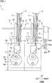
- FIG. 1 is a front view of the spun yarn take-up machine 1.
- the spun yarn take-up machine 1 includes plural spinning apparatuses 2, plural take-up units 3 provided to correspond to the respective spinning apparatuses 2, a yarn threading robot 4 (an automatic yarn threading device of the present invention), and an integrated controller 100 (see FIG. 3 ).
- the spinning apparatuses 2 are aligned in the left-right direction. Each spinning apparatus 2 spins out plural yarns Y (e.g., 12 yarns) .
- the take-up units 3 are located below the spinning apparatuses 2. The take-up units 3 are aligned in the left-right direction to correspond to the respective spinning apparatuses 2.
- Each take-up unit 3 is configured to take up yarns Y spun out from the spinning apparatus 2 and form packages P by simultaneously winding the yarns Y onto plural (e.g., 12) bobbins B.
- the yarn threading robot 4 is configured to move along a rail 5 extending in the left-right direction and to perform yarn threading to each take-up unit 3.
- the integrated controller 100 (see FIG. 3 ) is, for example, a typical computer.
- the integrated controller 100 is electrically connected to unit controllers 101 configured to control the respective take-up units 3 and a yarn threading controller 102 configured to control the yarn threading robot 4 (see FIG. 3 ).
- the integrated controller 100 integrally controls the entire spun yarn take-up machine 1 in association with the unit controllers 101 and the yarn threading controller 102.
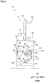
- FIG. 2 is a side view of the take-up unit 3 and the yarn threading robot 4.
- FIG. 3 is a block diagram showing an electric structure of the spun yarn take-up machine 1.
- the take-up unit 3 includes an aspirator 11, a regulatory guide 12, a first godet roller 13, a second godet roller 14, and a winding unit 15.
- the aspirator 11 is provided at a front end portion of the take-up unit 3.
- the aspirator 11 is arranged to suck and retain yarns spun out from the spinning apparatus 2 in advance, before yarn threading to the take-up unit 3.
- the regulatory guide 12 is, for example, a known comb-teeth-shaped yarn guide. As shown in FIG. 2 , the regulatory guide 12 is provided below the aspirator 11. The first regulatory guide 12 is arranged to cause the yarns Y to be lined up in the left-right direction. The regulatory guide 12 regulates the movement of the yarns Y in the left-right direction such that, when the yarns Y are threaded, the interval between neighboring yarns Y is equal to a predetermined distance. The regulatory guide 12 is moved in the left-right direction by, e.g., an air cylinder 111 (as shown in FIG. 3 ). The regulatory guide 12 is movable between a production position (see two-dot chain lines in FIG. 9(d) ) where the yarns Y are wound onto the bobbins B and a yarn threading position (see solid lines in FIG. 9(d) ) where yarn threading is performed.
- the first godet roller 13 is a roller having an axis substantially in parallel to the left-right direction. As shown in FIG. 2 , the first godet roller 13 is provided below the regulatory guide 12. The first godet roller 13 is rotationally driven by an unillustrated motor so as to feed the yarns Y to the downstream side in the yarn running direction.
- the second godet roller 14 is a roller having an axis substantially in parallel to the left-right direction. As shown in FIG. 2 , the second godet roller 14 is provided above and rearward of the first godet roller 13. The second godet roller 14 is rotationally driven by an unillustrated motor so as to feed the yarns Y to the downstream side in the yarn running direction. The second godet roller 14 is movably supported by a guide rail 16 which obliquely extends upward and rearward. The second godet roller 14 is movable along a guide rail 16 by, for example, a movement motor 112 (see FIG. 3 ) and unillustrated members such as a pulley pair, a belt, and an air device.
- a movement motor 112 see FIG. 3
- the second godet roller 14 is movable between a production position (indicated by solid lines in FIG. 2 ) where the yarns Y are wound onto the bobbins B and a yarn threading position (indicated by two-dot chain lines in FIG. 2 ) where the second godet roller 14 is close to the first godet roller 13 and yarn threading is carried out.
- the winding unit 15 is configured to form packages P by winding the yarns Y onto the respective bobbins B. As shown in FIG. 2 , the winding unit 15 is provided below members such as the first godet roller 13 and the second godet roller 14.
- the winding unit 15 includes a frame 20, fulcrum guides 21 (a yarn threading target member of the present invention), traverse guides 22, a turret 23, two bobbin holders 24, a contact roller 25, and a unit controller 101.
- the frame 20 is a member which is placed on, for example, a floor of a factory, and to which components of the winding unit 15 are attached or in which components of the winding unit 15 are accommodated.
- the frame 20 includes a base portion 20a which is provided on the floor surface and extends in the front-rear direction, a rear portion 20b which vertically extends from a rear end portion of the base portion 20a, and an upper portion 20c which extends forward from an upper part of the rear portion 20b.
- Each of the fulcrum guides 21 is a guide about which a yarn Y is traversed by each traverse guide 22. As shown in FIG. 2 , the fulcrum guides 21 are provided for the respective yarns Y and are aligned in the front-rear direction. Each fulcrum guide 21 has a groove 21a (see FIG. 5(a) and FIG. 5(b) ) which is open to the rear side. A yarn Y can be housed in each fulcrum guide 21 as the yarn Y is inserted into the groove 21a from the rear side. Each fulcrum guide 21 has a cylindrical attachment portion 21b that is open in the front-rear direction.
- the attachment portion 21b is movably attached to a guide supporter 26 that extends in the front-rear direction (see FIG. 5(a) and FIG. 5(b) ).
- the guide supporter 26 is, for example, a hollow cylindrical member fixed to the upper portion 20c of the frame 20.
- the fulcrum guides 21 are moved in the front-rear direction along the guide supporter 26 by a later-described driving unit 30.
- the traverse guides 22 are provided for the respective yarns Y, and are aligned in the front-rear direction.
- Each traverse guide 22 is, for example, a known blade-type guide.
- the traverse guide 22 is reciprocally driven in the front-rear direction by, for example, an unillustrated motor. Because of this, the yarns Y are traversed about the fulcrum guides 21 in the front-rear direction.
- the turret 23 is a disc-shaped member having an axis substantially parallel to the front-rear direction.
- the turret 23 is rotationally driven by a motor which is not illustrated.
- the two bobbin holders 24 have axes in parallel to the front-rear direction, respectively, and are rotatably supported at an upper end portion and a lower end portion of the turret 23.
- the bobbins B provided for the respective yarns Y are attached to each bobbin holder 24 so as to be aligned in the front-rear direction (bobbin axial direction), and are rotatably supported by each bobbin holder 24.
- Each of the two bobbin holders 24 is rotationally driven by an individual motor (not illustrated).
- the contact roller 25 is a roller having an axis substantially parallel to the front-rear direction, and is provided immediately above the upper bobbin holder 24.
- the contact roller 25 is configured to make contact with the surfaces of the packages P supported by the upper bobbin holder 24. With this, the contact roller 25 applies a contact pressure to the surfaces of the unfinished packages P, to adjust the shape of each package P.
- the unit controller 101 includes members such as a CPU, a ROM, and a RAM, and is configured to control members such as the air cylinder 111 and the movement motor 112.
- the unit controller 101 further includes an operation unit 121 (as shown in FIG. 3 ) provided so as to be operated by an operator, and a notification unit 122 (as shown in FIG. 3 ) for notifying the operator of information.
- the operation unit 121 includes, e.g., an unillustrated operation button.
- the notification unit 122 includes, e.g., an unillustrated alarm lamp.
- the unit controller 101 is electrically connected to the integrated controller 100 (as shown in FIG. 3 ), and communicates with the integrated controller 100.
- the yarns Y traversed by the traverse guides 22 are wound onto the bobbins B, with the result that the packages P are formed.
- the turret 23 is rotated to switch over the upper and lower positions of the two bobbin holders 24.
- the bobbin holder 24 having been at the lower position is moved to the upper position, which allows the yarns Y to be wound onto the bobbins B attached to the bobbin holder 24 having been moved to the upper position, to form packages P.
- FIG. 4 shows the drive unit 30.
- FIG. 5(a) and FIG. 5(b) show the movement of the fulcrum guides 21.
- the drive unit 30 includes an air cylinder 31 and a movable member 32. As the air cylinder 31 moves the movable member 32 connected to the rearmost fulcrum guide 21, the fulcrum guides 21 are moved.
- the air cylinder 31 is, for example, a rodless cylinder extending in the front-rear direction.
- the air cylinder 31 is controlled by the unit controller 101 (see FIG. 3 ).
- the air cylinder 31 is, for example, accommodated inside the guide supporter 26.
- the air cylinder 31 includes a cylinder main body 33, a piston 34 accommodated in the cylinder main body 33 and movable in the front-rear direction, and a slider 35 connected to the piston 34 and provided outside the cylinder main body 33.
- the cylinder main body 33 extends in the front-rear direction. Inside the cylinder main body 33, a cylinder chamber 33a and a cylinder chamber 33b are formed.
- the cylinder chamber 33a is formed in front of the piston 34.
- the cylinder chamber 33a is connected to a pipe 36a extending toward the outer side of the guide supporter 26.
- the cylinder chamber 33b is formed behind the piston 34.
- the cylinder chamber 33b is connected to the pipe 36b extending toward the outer side of the guide supporter 26.
- the pipe 36a and the pipe 36b are connected to a supply port (not illustrated) for supplying compressed air or a discharge port (not illustrated) for discharging compressed air, via, for example, a known four-way electromagnetic valve (not illustrated).
- the four-way electromagnetic valve is able to switch the state of the drive unit 30 between a first state and a second state that are described below.
- the pipe 36a In the first state, the pipe 36a is connected to the supply port whereas the pipe 36b is connected to the discharge port.
- the pipe 36b In the second state, the pipe 36b is connected to the supply port whereas the pipe 36a is connected to the discharge port.
- the drive unit 30 When the drive unit 30 is in the first state, compressed air is supplied to the cylinder chamber 33a whereas compressed air is discharged from the cylinder chamber 33b.
- the piston 34 and the slider 35 move rearward (as indicated by solid lines in FIG. 4 ).
- the piston 34 and the slider 35 move forward (as indicated by two-dot chain lines in FIG. 4 ).
- an unillustrated magnet To the slider 35, for example, an unillustrated magnet is fixed.
- the movable member 32 is attached to the guide supporter 26 and is arranged to be movable in the front-rear direction (bobbin axial direction) along the guide supporter 26.
- the rearmost fulcrum guide 21 (fulcrum guide 21R) is fixed (see FIG. 5(a) and FIG. 5(b) ).
- an unillustrated magnet is fixed to the movable member 32.
- the movable member 32 is therefore connected to the slider 35 by magnetic force.
- the movable member 32 follows the slider 35 on account of the magnet force, and moves in the bobbin axial direction together with the fulcrum guide 21R (which is the rearmost one of the fulcrum guides 21).
- the above-described fulcrum guides 21 are connected to one another by, for example, an unillustrated belt.
- two fulcrum guides 21 neighboring each other in the front-rear direction (bobbin axial direction) are connected to each other by the belt.
- the movable member 32 and the fulcrum guide 21R move rearward, the other fulcrum guides 21 are pulled by the belt and move rearward.
- the fulcrum guide 21R reaches the rear end of the movable range, the fulcrum guides 21 are lined up at substantially equal intervals that are defined by the length of the belt (see FIG. 5(a) ). In this state, the fulcrum guides 21 are positioned directly above the corresponding bobbins B (see FIG. 2 )).
- the position of the fulcrum guides 21 in this state is termed a distanced position (equivalent to a production position in the present invention) .
- a distanced position (equivalent to a production position in the present invention)
- the attachment portion 21b of each of the other fulcrum guides 21 is pressed by the fulcrum guide 21R.
- the fulcrum guides 21 move to gather on the front side.
- the fulcrum guides 21 are close to one another (i.e., the intervals are narrow) as compared to the case where the fulcrum guides 21 are at the distanced position.
- the position of the fulcrum guides 21 in this state is termed a gathered position (equivalent to a yarn threading position in the present invention). In this way, the fulcrum guides 21 are movable between the distanced position and the gathered position different from the distanced position.
- the take-up unit 3 includes a yarn threading execution unit 40 (as shown in FIG. 6 ) configured to thread the yarns Y having been threaded to the fulcrum guides 21 to the traverse guides 22 and the bobbins B.
- a yarn threading execution unit 40 (as shown in FIG. 6 ) configured to thread the yarns Y having been threaded to the fulcrum guides 21 to the traverse guides 22 and the bobbins B.
- FIG. 6 is a schematic representation of the yarn threading execution unit 40.
- FIGs. 7(a) and 7(b) show a later-described first separator 42.
- FIG. 7(c) shows a second separator 43 described later, viewed along an arrow VII in FIG. 6 .
- the yarn threading execution unit 40 includes, for example, a yarn convergence guide 41, the first separator 42, and the second separator 43.
- the yarn convergence guide 41 is configured to converge the yarns Y at a front end portion of the take-up unit 3.
- the first separator 42 temporarily holds the yarns Y having been threaded to the respective fulcrum guides 21.
- the second separator 43 performs operations such as receiving the yarns Y from the first separator 42 and moving the yarns Y to positions close to the bobbins B.
- the yarn convergence guide 41 is provided at a front end portion of the take-up unit 3. As shown in FIG. 1 , the yarn convergence guide 41 is attached to a leading end of an arm-like swing member 44 which is swingable about the front-rear direction which is a swing axial direction. The swing member 44 is swung by, e.g., an air cylinder 113 (as shown in FIG. 3 ). Because of this, the yarn convergence guide 41 is swingable between an initial position (indicated by solid lines in FIG. 6 ) positioned at a right end portion of the take-up unit 3 and a handover position (indicated by dotted lines in FIG. 6 ) which is to the left of the initial position.
- an initial position indicated by solid lines in FIG. 6
- a handover position indicated by dotted lines in FIG. 6
- the first separator 42 includes a guide member 51 extending in the front-rear direction and holding units 52 movably attached to the guide member 51 so as to be aligned in the front-rear direction.
- the guide member 51 is configured to be movable in the left-right direction by, e.g., an air cylinder 114 (as shown in FIG. 3 ).
- the guide member 51 is movable between an initial position (as shown by sold lines in FIG. 6 ) and a handover position (as shown by dotted lines in FIG. 6 ) to the left of the initial position. As shown in FIGs.
- each holding unit 52 includes a main body 52a and a protrusion 52b that prevents the yarns Y from dropping off.
- the holding units 52 are connected to each other by, e.g., an unillustrated belt, and moved in the front-rear direction by, e.g., an air cylinder 115 (as shown in FIG. 3 ).
- the holding units 52 are movable between a first position (as shown in FIG. 7(a) ) where intervals of the holding units 52 in the front-rear direction are substantially identical with the intervals of the bobbins B in the front-rear direction and a second position (as shown in FIG. 7(b) ) where the holding units 52 are gathered on the front side as compared to the first positions.
- the second separator 43 is provided to the left of the first separator 42.
- the second separator 43 includes an arm-like swing member 53 which extends in the front-rear direction and which is swingable about a swing axial center parallel to the front-rear direction, and holding units 54 fixed to a leading end of the swing member 53.
- insertion spaces 54a into which the yarns Y are inserted are formed at the end portions of the holding units 54 opposite to the swing member 53, so as to be aligned in the front-rear direction.
- protrusions 54b and 54c are provided to prevent the yarns Y from dropping off.
- the swing member 53 and the holding units 54 are swung by, e.g., an air cylinder 116 (as shown in FIG. 3 ).
- the swing member 53 and the holding units 54 are therefore movable between a predetermined retracted position (indicated by solid lines in FIG. 6 ) and a receiving position (indicated by dotted lines in FIG. 6 ) to the right of the retracted position, where the yarns Y are received from the first separator 42.
- the second separator 43 is arranged to be able to cause the reciprocating traverse guides 22 to capture the yarns Y by moving the holding units 54 leftward from the receiving position after receiving the yarns Y from the first separator 42.
- the yarn threading execution unit 40 includes an unillustrated yarn gathering unit.
- the yarn gathering unit is arranged to temporarily detach a yarn Y captured by the traverse guide 22 from the traverse guide 22 and guides the detached yarn Y to an unillustrated slit of a bobbin B.
- the yarn gathering unit is not detailed in this disclosure. For details, see Japanese Unexamined Patent Publication No. 2017-154891 , for example.
- the yarn threading robot 4 includes a main body 61, a robotic arm 62, a yarn threading unit 63, and a yarn threading controller 102 (see FIG. 3 ).
- the main body 61 is substantially rectangular parallelepiped in shape.
- the main body 61 is moved in the left-right direction by a movement motor 131 (see FIG. 3 ).
- the robotic arm 62 is attached to the lower surface of the main body 61.
- the robotic arm 62 includes arms 62a and joints 62b connecting the arms 62a with each other. Each joint 62b incorporates therein an arm motor 132 (see FIG. 3 ). As the arm motor 132 is driven, the arms 62a are swung about the joints 62b.
- the yarn threading unit 63 is attached to a leading end portion of the robotic arm 62.
- the yarn threading unit 63 includes a suction 64, a cutter 65, and a yarn threading assisting member 66 (see FIG.
- the suction 64 is configured to suck and retain the yarns Y during the yarn threading.
- the cutter 65 is configured to cut the yarns Y when the yarns Y are handed over from the aspirator 11 to the yarn threading unit 63 (described later).
- the yarn threading assisting member 66 includes retaining grooves 66a (see FIG. 5(b) ) and retains the yarns Y by the respective retaining grooves 66a.
- the yarn threading controller 102 includes a CPU, a ROM, and a RAM, and is configured to control the movement motor 131, the arm motor 132, and the yarn threading unit 63. After moving the main body 61 to a position in front of a take-up unit 3 which is the target of yarn threading, the yarn threading controller 102 performs the yarn threading to that take-up unit 3 by controlling the robotic arm 62, while causing the yarn threading unit 63 to retain the yarns Y.
- the yarn threading controller 102 is electrically connected to the integrated controller 100 (as shown in FIG. 3 ), and communicates with the integrated controller 100.
- the movement of the fulcrum guides 21 is completed when, for example, a predetermined time elapses from the start of the movement of the fulcrum guides 21 by the unit controller 101, and yarn threading is performed by the yarn threading robot 4.
- the air cylinder 31 does not properly operate and the fulcrum guides 21 do not properly move
- the fulcrum guides 21 are not properly located at the gathered position or the distanced position.
- the yarn threading robot 4 may fail the yarn threading.
- a reason why the air cylinder 31 does not properly operate is, for example, increase in a load on account of clogging due to yarn dust between the cylinder main body 33 and the slider 35.
- the yarn dust include, for example, powder generated as part of the running yarn Y is ground due to abrasion with a guide member such as a fulcrum guide 21. Because such yarn dust may enter, for example, the internal space of the guide supporter 26, it is difficult to completely prevent the clogging due to yarn dust.
- Another reason is that, when a supply source of compressed air is shared between a lot of air cylinders including the air cylinder 31, the pressure of the compressed air may be insufficient when plural air cylinders operate simultaneously. In such a case, the air cylinder are less likely to operate properly.
- the spun yarn take-up machine 1 is arranged as described below, in order to suppress defects that may occur when the fulcrum guides 21 (yarn threading target members) do not properly move.
- a later-described location information detection unit 70 is provided in the vicinity of the fulcrum guides 21.
- the structure of the spun yarn take-up machine 1 (to be more specific, the structure at around the fulcrum guide 21) will be detailed.
- the movable member 32 is attached to the guide supporter 26 to be movable in the front-rear direction.
- a left end portion of the movable member 32 for example, protrudes leftward as compared to the left end of each fulcrum guide 21.
- the location information detection unit 70 (a detection unit of the present invention) is provided to detect information regarding the current location of the fulcrum guides 21.
- the location information detection unit 70 is configured to detect information regarding the movement of the fulcrum guides 21.
- the location information detection unit 70 includes a first limit switch 71 and a second limit switch 72 (both of which correspond to a limit switch of the present invention) that are configured to detect information indicating whether the fulcrum guides 21 are at a target position.
- the first limit switch 71 and the second limit switch 72 are, for example, switch devices in each of which a known touch-type micro switch is provided.
- the driving mechanism of the micro switch may be a known plunger, hinge lever, or the like.
- the first limit switch 71 and the second limit switch 72 (limit switches) may be known contactless proximity sensors.
- the first limit switch 71 and the second limit switch 72 are electrically connected to the unit controller 101. The descriptions below assume that the first limit switch 71 and the second limit switch 72 are contact-type limit switches.
- the first limit switch 71 is arranged to detect whether the movable member 32 and the fulcrum guide 21R (the rearmost one of the fulcrum guides 21) are properly at the gathered position. As shown in FIG. 5(a) and FIG. 5(b) , the first limit switch 71 is provided in front of the left end portion of the movable member 32. The first limit switch 71 is provided to the left of the fulcrum guides 21. The fulcrum guides 21 do not therefore interfere with the first limit switch 71 when moving in the bobbin axial direction. The first limit switch 71 is arranged to make contact with the left end portion of the movable member 32 when the movable member 32 reaches the gathered position.
- the first limit switch 71 When the movable member 32 is in contact with the first limit switch 71, the first limit switch 71 is in an on state. When the movable member 32 is not in contact with the first limit switch 71, the first limit switch 71 is in an off state. With this arrangement, the first limit switch 71 is able to detect information regarding whether the movement of the movable member 32 to the gathered position is properly done. In connection with the first limit switch 71, the gathered position is equivalent to a target position of the present invention.
- the second limit switch 72 is arranged to detect whether the movable member 32 and the fulcrum guide 21R are properly positioned at the distanced position. As shown in FIG. 5(a) and FIG. 5(b) , the second limit switch 72 is provided behind the left end portion of the movable member 32. The second limit switch 72 is provided at a substantially same position as the first limit switch 71 in the left-right direction. Furthermore, the second limit switch 72 is provided to overlap the left end portion of the movable member 32 in the left-right direction. The second limit switch 72 is arranged to make contact with the left end portion of the movable member 32 when the movable member 32 reaches the distanced position.
- the second limit switch 72 When the movable member 32 is in contact with the second limit switch 72, the second limit switch 72 is in an on state. When the movable member 32 is not in contact with the second limit switch 72, the second limit switch 72 is in an off state. With this arrangement, the second limit switch 72 is able to detect information regarding whether the movement of the movable member 32 to the distanced position is properly done. In connection with the second limit switch 72, the distanced position is equivalent to a target position of the present invention.
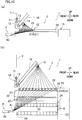
- FIG. 8 is a flowchart of processes of the yarn threading.
- FIG. 9(a) to FIG. 11 is an explanatory view of the processes of the yarn threading.
- FIG. 9(d) is viewed along an arrow D in FIG. 9(c) .
- the yarn threading is performed as the integrated controller 100, the unit controller 101, and the yarn threading controller 102 cooperate and control the components of the take-up unit 3 and the components of the yarn threading robot 4.
- a combination of the integrated controller 100, the unit controller 101, and the yarn threading controller 102 is equivalent to a controller of the present invention.
- the yarns Y are sucked and retained by the aspirator 11 (see FIG. 9(a) ).
- the yarn threading starts in this state (S101).
- a signal that instructs a take-up unit 3 to perform an operation necessary for the yarn threading is sent from the integrated controller 100 to the unit controller 101 of a take-up unit 3 which is the target of yarn threading.
- a signal which instructs the main body 61 of the yarn threading robot 4 to move to a position in front of that take-up unit 3 is sent from the integrated controller 100 to the yarn threading controller 102.
- the yarn threading controller 102 controls the movement motor 131 in accordance with the signal to move the main body 61 in the left-right direction.
- the unit controller 101 then controls the components of the take-up unit 3 to start to move the components that are targets of the yarn threading from the production position to the yarn threading position (S102).
- the movement motor 112 starts to move the second godet roller 14 to the yarn threading position and the air cylinder 31 starts to move the fulcrum guides 21 to the gathered position (yarn threading position).
- the unit controller 101 determines whether the fulcrum guides 21 properly reach the gathered position (yarn threading position) before a predetermined time elapses from the start of the movement of the fulcrum guides 21.
- the unit controller 101 determines that the fulcrum guides 21 properly reach the gathered position. Meanwhile, when the first limit switch 71 is in the off state (No in S103), the unit controller 101 repeats the step S103 until a predetermined time elapses (No in S104).
- the unit controller 101 determines that a defect occurs in the movement of the fulcrum guides 21 to the gathered position.
- the yarn threading is stopped accordingly.
- the unit controller 101 stops the components of the take-up unit 3 and sends a signal indicating that a defect has occurred in the movement of the fulcrum guides 21, to the integrated controller 100.
- the integrated controller 100 sends a signal instructing the stop of the yarn threading to the yarn threading controller 102.
- the unit controller 101 controls a notification unit 122 to output information indicating that a defect has occurred in the movement of the fulcrum guides 21 (S105). Based on the information notified by the notification unit 122, the operator checks the state of the take-up unit 3. In addition to this, the operator performs maintenance of the take-up unit 3 according to need.
- the unit controller 101 immediately sends a signal indicating that the movement of the fulcrum guides 21 is proper to the integrated controller 100. Based on the signal sent from the unit controller 101, the integrated controller 100 sends a signal instructing the continuation of the operation of the yarn threading robot 4 to the yarn threading controller 102. Based on this signal, the yarn threading controller 102 operates the yarn threading robot 4. To be more specific, the yarns Y are cut by the cutter 65 while the suction 64 is positioned in the vicinity of the yarns Y sucked and retained by the aspirator 11.
- the yarn threading robot 4 performs the yarn threading to the regulatory guide 12, the first godet roller 13, and the second godet roller 14.
- the yarn threading controller 102 moves, by using the robotic arm 62, the leading end portion of the yarn threading unit 63 to a location which is below, behind, and to the right of the first regulatory guide 12 (see FIG. 9(c) and two-dot chain lines in FIG. 9(d) ).
- the unit controller 101 then moves the regulatory guide 12 from the production position (see two-dot chain lines in FIG. 9(d) ) to the yarn threading position (see solid lines in FIG. 9(d) ).
- the yarn threading controller 102 moves the yarn threading unit 63 forward so as to thread the yarns Y to the regulatory guide 12. Subsequently, the yarn threading controller 102 moves the leading end portion of the yarn threading unit 63 to the base end side in the axial direction of the first godet roller 13 (see FIG. 9(e) ). At the same time, the unit controller 101 moves the first regulatory guide 12 from the yarn threading position to the production position (see FIG. 9(e) ). Subsequently, the yarn threading controller 102 moves the yarn threading unit 63 so as to thread the yarns Y to the first godet roller 13 and to the second godet roller 14 in order (see FIG. 9(f) ).
- the yarn threading robot 4 performs the yarn threading to the fulcrum guides 21.
- the yarns Y are retained to be distanced from one another by the yarn threading assisting member 66 of the yarn threading unit 63 (see FIG. 5(b) ).
- the yarn threading controller 102 controls the robotic arm 62 to move the yarn threading unit 63 to a predetermined position on the rear side (see two-dot chain lines in FIG. 5(b) ).
- the yarn threading controller 102 moves the yarn threading unit 63 obliquely leftward and forward (as indicated by an arrow in FIG. 5(b) ).
- the yarns Y are threaded to the corresponding fulcrum guides 21 (see FIG. 10(a) ).
- the unit controller 101 starts to move the second godet roller 14 and the fulcrum guides 21 to the production position. Subsequently, the unit controller 101 determines whether the fulcrum guides 21 properly return the distanced position (production position) before a predetermined time elapses from the start of the movement of the fulcrum guides 21.
- the unit controller 101 determines that the fulcrum guide 21 properly reach the distanced position. Meanwhile, when the second limit switch 72 is in the off state (No in S110), the unit controller 101 repeats the step S110 until a predetermined time elapses (No in S111) .
- the unit controller 101 determines that a defect occurs in the movement of the fulcrum guides 21 to the distanced position.
- the yarn threading is stopped accordingly, in the same manner as in the step S105.
- the unit controller 101 controls a notification unit 122 to output information indicating that a defect has occurred in the movement of the fulcrum guides 21 (S112).
- the unit controller 101 sends a signal indicating that the movement of the fulcrum guides 21 is proper to the integrated controller 100. Furthermore, the unit controller 101 moves the yarn convergence guide 41 from an initial position (see solid lines in FIG. 6 ) to a handover position (see dotted lines in FIG. 6 ). Furthermore, the unit controller 101 moves holding units 52 of the first separator 42 from a first position to a second position (see FIG. 7(b) and FIG. 10(b) ).
- the integrated controller 100 Based on the signal sent from the unit controller 101, the integrated controller 100 sends a signal instructing the continuation of the operation of the yarn threading robot 4 to the yarn threading controller 102. Based on this signal, the yarn threading controller 102 operates the yarn threading robot 4. Subsequently, the yarn threading controller 102 moves the yarn threading unit 63 by using the robotic arm 62 and threads the yarns Y to the yarn convergence guide 41 (S113). Because of this, the yarns Y are placed immediately behind the corresponding holding units 52, respectively (see FIG. 7(b) and FIG. 10(b) ).
- the unit controller 101 returns the holding units 52 to the first position (see FIG. 7(a) and FIG. 11 ) and moves the second separator 43 to the receiving position (see dotted lines in FIG. 6 ). Furthermore, the unit controller 101 moves the first separator 42 to the handover position (see dotted lines in FIG. 6 ) and then moves the holding units 52 to the second position again. Because of this, the yarns Y are handed over from the first separator 42 to the second separator 43 (this action is not shown in the figures). Thereafter, the unit controller 101 moves the holding units 54 of the second separator 43 leftward from the receiving position (this action is not shown in the figures).
- the unit controller 101 causes a yarn gathering unit (not illustrated) to temporarily detach the yarns Y from the traverse guides 22 and guide the yarns Y to slits of the bobbins B. In this way, the yarns Y are threaded to the bobbins B. Thereafter, the unit controller 101 causes the yarn gathering unit to return the yarns Y to positions where the yarns Y are caught by the traverse guides 22. When the yarns Y are caught by the traverse guides 22 again, the yarn threading is finished and winding of the yarns Y by the take-up unit 3 starts (S115).
- the yarn threading can be performed when it is determined that the movement of the fulcrum guides 21 is properly done, and the yarn threading may be, for example, terminated when it is determined that the movement of the yarn threading target member is not properly done. It is therefore possible to suppress defects that may occur when the fulcrum guides 21 do not properly move.
- the operation of the yarn threading robot 4 is continued only when it is determined that the movement of the fulcrum guides 21 is properly done. It is therefore possible to reliably prevent unintentional yarn threading by the yarn threading robot 4, when there is a defect in the movement of the fulcrum guides 21.
- the location information detection unit 70 is configured to detect information regarding the location of the fulcrum guides 21. It is possible to easily determine whether the movement of the fulcrum guides 21 is properly done, by utilizing such information.
- the location information detection unit 70 because a limit switch that is typically inexpensive is used as the location information detection unit 70, it is possible to easily determine whether the yarn threading target member has reached the target position, while suppressing the increase in production cost of the textile machine.
- the thrust force of the air cylinder 31 of the drive unit 30 is typically lower than that of, for example, an electric motor, the movement of the fulcrum guides 21 may be obstructed even by, for example, slight clogging due to yarn dust. In such an arrangement, determination of whether the movement of the fulcrum guides 21 is proper or not based on a result of detection by the location information detection unit 70 is effective.
- the fulcrum guides 21 (in particular the rearmost fulcrum guide 21R) are required to move over a long distance between the distanced position and the gathered position. On this account, the fulcrum guides 21 are likely to fail to reach the target position when the drive unit 30 does not properly operate. In such an arrangement, determination of whether the movement of the fulcrum guides 21 is proper or not based on a result of detection by the location information detection unit 70 is effective.
- the yarns Y threaded to the fulcrum guides 21 may not be properly wound onto the bobbins B, and hence the yarns wound onto the bobbins B may be wasteful.
- determination of whether the movement of the fulcrum guides 21 to the distanced position is proper or not based on a result of detection by the second limit switch 72 of the location information detection unit 70 is effective.
- the yarn threading to the fulcrum guides 21 may not be properly done.
- determination of whether the movement of the fulcrum guides 21 to the gathered position is proper or not based on a result of detection by the first limit switch 71 of the location information detection unit 70 is effective.
Landscapes
- Engineering & Computer Science (AREA)
- Quality & Reliability (AREA)
- Mechanical Engineering (AREA)
- Textile Engineering (AREA)
- Replacing, Conveying, And Pick-Finding For Filamentary Materials (AREA)
- Spinning Methods And Devices For Manufacturing Artificial Fibers (AREA)
Abstract
Description
- The present invention relates to a textile machine.
- A spun yarn take-up machine (textile machine) recited in each of
Patent Literatures 1 and 2 (Japanese Laid-Open Patent Publication No.2017-82379 2015-78455 - When a drive unit such as the air cylinder does not properly operate on account of, for example, clogging due to yarn dust, a yarn threading target member such as the fulcrum guides cannot properly move. In such a case, the following defect occurs, for example.
- Although not described in
Patent Literature 1, in an arrangement in which a yarn is threaded to a yarn threading target member by a yarn threading robot, it is considered, for example, that movement of the yarn threading target member is completed when a predetermined time elapses from the start of the movement, and then yarn threading is performed. On this account, the yarn threading may not be successfully done if the yarn threading is performed in a state in which the yarn threading target member is displaced from the desired position. - Furthermore, no matter whether the yarn threading is performed by the yarn threading robot or the operator, winding of the yarn may start in a state in which the fulcrum guides are displaced from the desired position, if the fulcrum guides do not properly return the production position. As a result, packages may not be properly formed.
- An object pf the present invention is to suppress defects that may occur when a yarn threading target member does not properly move.
- According to a first aspect of the invention, a textile machine that processes at least one yarn includes: a yarn threading target member to which the at least one yarn is threaded; a drive unit configured to move the yarn threading target member between a predetermined production position and a yarn threading position different from the production position; a detection unit configured to detect information regarding movement of the yarn threading target member by the drive unit; and a controller, the controller determining whether the movement of the yarn threading target member is proper based on a result of detection by the detection unit.
- According to this aspect of the invention, the yarn threading can be performed when it is determined that the movement of the yarn threading target member is properly done, and the yarn threading may be, for example, terminated when it is determined that the movement of the yarn threading target member is not properly done. It is therefore possible to suppress defects that may occur when the yarn threading target member does not properly move.
- According to a second aspect of the invention, the textile machine of the first aspect further includes an automatic yarn threading device configured to perform yarn threading to the yarn threading target member, the controller continuing an operation of the automatic yarn threading device only when it is determined that the movement of the yarn threading target member is proper.
- It is therefore possible in this aspect to reliably prevent unintentional yarn threading by the yarn threading robot, when there is a defect in the movement of the yarn threading target member.
- According to a third aspect of the invention, the textile machine of the first or second aspect further includes a notification unit configured to notify information, when it is determined that a failure occurs in the movement of the yarn threading target member, the controller causing the notification unit to notify information indicating occurrence of a failure.
- According to this aspect of the invention, when there is a defect in the movement of the yarn threading target member, the operator is prompted to perform an immediate action.
- According to a fourth aspect of the invention, the textile machine of any one of the first to third aspects is arranged such that the detection unit is configured to detect information regarding a position of the yarn threading target member.
- According to this aspect of the invention, it is possible to easily determine whether the movement of the yarn threading target member is proper, by using the information regarding the position of the yarn threading target member.
- According to a fifth aspect of the invention, the textile machine of the fourth aspect is arranged such that the location information detection unit is a limit switch configured to detect information indicating whether the yarn threading target member is at a target position.
- According to this aspect of the invention, because a limit switch that is typically inexpensive is used, it is possible to easily determine whether the yarn threading target member has reached the target position, while suppressing the increase in production cost of the textile machine.
- According to a sixth aspect of the invention, the textile machine of the fourth or fifth aspect is arranged such that the drive unit includes an air cylinder.
- Because the thrust force of the air cylinder is typically lower than that of, for example, an electric motor, the movement of the yarn threading target member may be obstructed even by, for example, slight clogging due to yarn dust. In such an arrangement, determination of whether the movement of the yarn threading target member is proper or not based on a result of detection by the location information detection unit is effective.
- According to a seventh aspect of the invention, the textile machine of any one of the first to fifth aspects is arranged such that the drive unit includes an electric motor.
- When, for example, a gap between the movable portion of the electric motor and a fixed portion is clogged with yarn dust or the like, the electric motor may be excessively loaded and broken. According to the aspect of the invention, the electric motor is stopped when it is determined that a defect has occurred in the movement of the yarn threading target member. It is therefore possible to suppress the load on the electric motor from becoming excessive.
- According to an eighth aspect of the invention, the textile machine of the seventh aspect is arranged such that the detection unit is configured to detect information regarding a position of a movable portion of the electric motor.
- According to this aspect of the invention, it is possible to indirectly obtain the information regarding the position of the yarn threading target member by utilizing the information regarding the position of the movable portion. It is therefore possible to determine whether the movement of the yarn threading target member is properly done, even when the information regarding the location of the yarn threading target member cannot be directly obtained.
- According to a ninth aspect of the invention, the textile machine of the seventh or eighth aspect is arranged such that the electric motor is a stepping motor, and the detection unit is configured to detect step-out of the stepping motor.
- According to this aspect of the invention, it is possible to determine whether the motor is properly driven by utilizing information regarding the step-out. It is therefore possible to determine whether the movement of the yarn threading target member is properly done, even when the information regarding the location of the yarn threading target member cannot be obtained.
- According to a tenth aspect of the invention, the textile machine of any one of the first to ninth aspects further includes: a bobbin holder which supports bobbins on which two or more yarns are wound, respectively, the supported bobbins being aligned in an axial direction of the bobbins; and traverse guides which are aligned in the axial direction to correspond to the respective bobbins and are configured to traverse the respective yarns, the yarn threading target member including fulcrum guides which are aligned in the axial direction to correspond to the respective traverse guides and function as fulcrums when the yarns are traversed, and the fulcrum guides being movable between: a distanced position which is the production position, where the yarns are wound onto the respective bobbins; and a gathered position which is the yarn threading position, where intervals of the fulcrum guides in the axial direction are short as compared to intervals of the fulcrum guides in the distanced position.
- Because the fulcrum guides are required to move between the distanced position and the gathered position over a long distance, the fulcrum guides are likely to fail to reach the target position when the drive unit does not properly operate. In such an arrangement, determination of whether the movement of the yarn threading target member is proper or not based on a result of detection by the detection unit is effective.
- According to an eleventh aspect of the invention, the textile machine of the tenth aspect is arranged such that the detection unit is configured to detect information regarding whether the fulcrum guides are properly provided at the distanced position.
- When the fulcrum guides are deviated from the distanced position at the time of the winding of the yarns onto the bobbins, the yarns threaded to the fulcrum guides may not be properly wound onto the bobbins, and hence the yarns wound onto the bobbins may be wasteful. In such an arrangement, determination of whether the movement of the fulcrum guides is proper or not based on a result of detection by the detection unit is effective.
- According to a twelfth aspect of the invention, the textile machine of the tenth or eleventh aspect is arranged such that the detection unit is configured to detect information regarding whether the fulcrum guides are properly provided at the gathered position.
- When the fulcrum guides are deviated from the gathered position at the time of the threading of the yarns to the fulcrum guides, the yarn threading to the fulcrum guides may not be properly done. In such an arrangement, determination of whether the movement of the fulcrum guides is proper or not based on a result of detection by the detection unit is effective.
-
-
FIG. 1 is a front elevation of a spun yarn take-up machine of an embodiment. -
FIG. 2 is a profile of members such as a take-up unit. -
FIG. 3 is a block diagram showing an electric structure of the spun yarn take-up machine. -
FIG. 4 shows a drive unit. - Each of
FIG. 5(a) and FIG. 5(b) illustrates movement of fulcrum guides. -
FIG. 6 is a schematic representation of a yarn threading execution unit. -
FIGs. 7(a) and 7(b) show a first separator, andFIG. 7(c) shows a second separator. -
FIG. 8 is a flowchart of processes of yarn threading. -
FIG. 9(a) to FIG. 9(f) are explanatory views of the processes of the yarn threading. -
FIG. 10(a) and FIG. 10(b) are explanatory views of the processes of the yarn threading. -
FIG. 11 is an explanatory view of the processes of the yarn threading. -
FIG. 12 shows a drive unit of a modification. -
FIG. 13 shows a drive unit of another modification. -
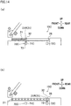
FIG. 14(a) and FIG. 14(b) are explanatory views of a location information detection unit of a further modification. - The following will describe an embodiment of the present invention. Hereinafter, directions shown in
FIG. 1 andFIG. 2 will be consistently used as an up-down direction, a left-right direction, and a front-rear direction, for convenience of explanation. The up-down direction is a vertical direction in which the gravity acts. The left-right direction is orthogonal to the up-down direction and is a direction in which later-described take-upunits 3 are aligned. The front-rear direction is a direction orthogonal to both the up-down direction and the left-right direction. Moreover, a direction in which a yarn Y runs is referred to as a yarn running direction. An axial direction of later-described bobbins B, which is substantially parallel to the front-rear direction, is referred to as a bobbin axial direction (axial direction of the present invention). - The following will outline a spun yarn take-up machine 1 (a textile machine of the present invention) of an embodiment, with reference to and
FIG. 1. FIG. 1 is a front view of the spun yarn take-upmachine 1. As shown inFIG. 1 , the spun yarn take-upmachine 1 includesplural spinning apparatuses 2, plural take-upunits 3 provided to correspond to therespective spinning apparatuses 2, a yarn threading robot 4 (an automatic yarn threading device of the present invention), and an integrated controller 100 (seeFIG. 3 ). - The spinning
apparatuses 2 are aligned in the left-right direction. Eachspinning apparatus 2 spins out plural yarns Y (e.g., 12 yarns) . The take-upunits 3 are located below the spinningapparatuses 2. The take-upunits 3 are aligned in the left-right direction to correspond to therespective spinning apparatuses 2. Each take-upunit 3 is configured to take up yarns Y spun out from thespinning apparatus 2 and form packages P by simultaneously winding the yarns Y onto plural (e.g., 12) bobbins B. Theyarn threading robot 4 is configured to move along arail 5 extending in the left-right direction and to perform yarn threading to each take-upunit 3. - The integrated controller 100 (see
FIG. 3 ) is, for example, a typical computer. Theintegrated controller 100 is electrically connected tounit controllers 101 configured to control the respective take-upunits 3 and ayarn threading controller 102 configured to control the yarn threading robot 4 (seeFIG. 3 ). Theintegrated controller 100 integrally controls the entire spun yarn take-upmachine 1 in association with theunit controllers 101 and theyarn threading controller 102. - The following will describe the structure of the take-up
unit 3 with reference toFIG. 2 andFIG. 3 .FIG. 2 is a side view of the take-upunit 3 and theyarn threading robot 4.FIG. 3 is a block diagram showing an electric structure of the spun yarn take-upmachine 1. As shown inFIG. 2 , the take-upunit 3 includes anaspirator 11, aregulatory guide 12, afirst godet roller 13, asecond godet roller 14, and a windingunit 15. - The
aspirator 11 is provided at a front end portion of the take-upunit 3. Theaspirator 11 is arranged to suck and retain yarns spun out from thespinning apparatus 2 in advance, before yarn threading to the take-upunit 3. - The
regulatory guide 12 is, for example, a known comb-teeth-shaped yarn guide. As shown inFIG. 2 , theregulatory guide 12 is provided below theaspirator 11. The firstregulatory guide 12 is arranged to cause the yarns Y to be lined up in the left-right direction. Theregulatory guide 12 regulates the movement of the yarns Y in the left-right direction such that, when the yarns Y are threaded, the interval between neighboring yarns Y is equal to a predetermined distance. Theregulatory guide 12 is moved in the left-right direction by, e.g., an air cylinder 111 (as shown inFIG. 3 ). Theregulatory guide 12 is movable between a production position (see two-dot chain lines inFIG. 9(d) ) where the yarns Y are wound onto the bobbins B and a yarn threading position (see solid lines inFIG. 9(d) ) where yarn threading is performed. - The
first godet roller 13 is a roller having an axis substantially in parallel to the left-right direction. As shown inFIG. 2 , thefirst godet roller 13 is provided below theregulatory guide 12. Thefirst godet roller 13 is rotationally driven by an unillustrated motor so as to feed the yarns Y to the downstream side in the yarn running direction. - The
second godet roller 14 is a roller having an axis substantially in parallel to the left-right direction. As shown inFIG. 2 , thesecond godet roller 14 is provided above and rearward of thefirst godet roller 13. Thesecond godet roller 14 is rotationally driven by an unillustrated motor so as to feed the yarns Y to the downstream side in the yarn running direction. Thesecond godet roller 14 is movably supported by aguide rail 16 which obliquely extends upward and rearward. Thesecond godet roller 14 is movable along aguide rail 16 by, for example, a movement motor 112 (seeFIG. 3 ) and unillustrated members such as a pulley pair, a belt, and an air device. With this, thesecond godet roller 14 is movable between a production position (indicated by solid lines inFIG. 2 ) where the yarns Y are wound onto the bobbins B and a yarn threading position (indicated by two-dot chain lines inFIG. 2 ) where thesecond godet roller 14 is close to thefirst godet roller 13 and yarn threading is carried out. - The winding
unit 15 is configured to form packages P by winding the yarns Y onto the respective bobbins B. As shown inFIG. 2 , the windingunit 15 is provided below members such as thefirst godet roller 13 and thesecond godet roller 14. The windingunit 15 includes aframe 20, fulcrum guides 21 (a yarn threading target member of the present invention), traverse guides 22, aturret 23, twobobbin holders 24, acontact roller 25, and aunit controller 101. - The
frame 20 is a member which is placed on, for example, a floor of a factory, and to which components of the windingunit 15 are attached or in which components of the windingunit 15 are accommodated. As shown inFIG. 2 , theframe 20 includes abase portion 20a which is provided on the floor surface and extends in the front-rear direction, arear portion 20b which vertically extends from a rear end portion of thebase portion 20a, and anupper portion 20c which extends forward from an upper part of therear portion 20b. - Each of the fulcrum guides 21 is a guide about which a yarn Y is traversed by each
traverse guide 22. As shown inFIG. 2 , the fulcrum guides 21 are provided for the respective yarns Y and are aligned in the front-rear direction. Each fulcrum guide 21 has agroove 21a (seeFIG. 5(a) and FIG. 5(b) ) which is open to the rear side. A yarn Y can be housed in each fulcrum guide 21 as the yarn Y is inserted into thegroove 21a from the rear side. Each fulcrum guide 21 has acylindrical attachment portion 21b that is open in the front-rear direction. Theattachment portion 21b is movably attached to aguide supporter 26 that extends in the front-rear direction (seeFIG. 5(a) and FIG. 5(b) ). Theguide supporter 26 is, for example, a hollow cylindrical member fixed to theupper portion 20c of theframe 20. When yarn threading is performed, the fulcrum guides 21 are moved in the front-rear direction along theguide supporter 26 by a later-describeddriving unit 30. - The traverse guides 22 are provided for the respective yarns Y, and are aligned in the front-rear direction. Each
traverse guide 22 is, for example, a known blade-type guide. Thetraverse guide 22 is reciprocally driven in the front-rear direction by, for example, an unillustrated motor. Because of this, the yarns Y are traversed about the fulcrum guides 21 in the front-rear direction. - The
turret 23 is a disc-shaped member having an axis substantially parallel to the front-rear direction. Theturret 23 is rotationally driven by a motor which is not illustrated. The twobobbin holders 24 have axes in parallel to the front-rear direction, respectively, and are rotatably supported at an upper end portion and a lower end portion of theturret 23. The bobbins B provided for the respective yarns Y are attached to eachbobbin holder 24 so as to be aligned in the front-rear direction (bobbin axial direction), and are rotatably supported by eachbobbin holder 24. Each of the twobobbin holders 24 is rotationally driven by an individual motor (not illustrated). - The
contact roller 25 is a roller having an axis substantially parallel to the front-rear direction, and is provided immediately above theupper bobbin holder 24. Thecontact roller 25 is configured to make contact with the surfaces of the packages P supported by theupper bobbin holder 24. With this, thecontact roller 25 applies a contact pressure to the surfaces of the unfinished packages P, to adjust the shape of each package P. - The unit controller 101 (see
FIG. 3 ) includes members such as a CPU, a ROM, and a RAM, and is configured to control members such as theair cylinder 111 and themovement motor 112. Theunit controller 101 further includes an operation unit 121 (as shown inFIG. 3 ) provided so as to be operated by an operator, and a notification unit 122 (as shown inFIG. 3 ) for notifying the operator of information. Theoperation unit 121 includes, e.g., an unillustrated operation button. Thenotification unit 122 includes, e.g., an unillustrated alarm lamp. Theunit controller 101 is electrically connected to the integrated controller 100 (as shown inFIG. 3 ), and communicates with theintegrated controller 100. - In the winding
unit 15 structured as described above, when theupper bobbin holder 24 is rotationally driven, the yarns Y traversed by the traverse guides 22 are wound onto the bobbins B, with the result that the packages P are formed. When the formation of the packages P is completed, theturret 23 is rotated to switch over the upper and lower positions of the twobobbin holders 24. As a result, thebobbin holder 24 having been at the lower position is moved to the upper position, which allows the yarns Y to be wound onto the bobbins B attached to thebobbin holder 24 having been moved to the upper position, to form packages P. - The following will describe the
drive unit 30 which is configured to move the fulcrum guides 21, with reference toFIG. 4 ,FIG. 5(a), and FIG. 5(b) .FIG. 4 shows thedrive unit 30.FIG. 5(a) and FIG. 5(b) show the movement of the fulcrum guides 21. As shown inFIG. 4 , thedrive unit 30 includes anair cylinder 31 and amovable member 32. As theair cylinder 31 moves themovable member 32 connected to therearmost fulcrum guide 21, the fulcrum guides 21 are moved. - The
air cylinder 31 is, for example, a rodless cylinder extending in the front-rear direction. Theair cylinder 31 is controlled by the unit controller 101 (seeFIG. 3 ). As shown inFIG. 4 , theair cylinder 31 is, for example, accommodated inside theguide supporter 26. Theair cylinder 31 includes a cylindermain body 33, apiston 34 accommodated in the cylindermain body 33 and movable in the front-rear direction, and aslider 35 connected to thepiston 34 and provided outside the cylindermain body 33. - The cylinder
main body 33 extends in the front-rear direction. Inside the cylindermain body 33, acylinder chamber 33a and acylinder chamber 33b are formed. Thecylinder chamber 33a is formed in front of thepiston 34. Thecylinder chamber 33a is connected to apipe 36a extending toward the outer side of theguide supporter 26. Thecylinder chamber 33b is formed behind thepiston 34. Thecylinder chamber 33b is connected to thepipe 36b extending toward the outer side of theguide supporter 26. Thepipe 36a and thepipe 36b are connected to a supply port (not illustrated) for supplying compressed air or a discharge port (not illustrated) for discharging compressed air, via, for example, a known four-way electromagnetic valve (not illustrated). The four-way electromagnetic valve is able to switch the state of thedrive unit 30 between a first state and a second state that are described below. In the first state, thepipe 36a is connected to the supply port whereas thepipe 36b is connected to the discharge port. In the second state, thepipe 36b is connected to the supply port whereas thepipe 36a is connected to the discharge port. When thedrive unit 30 is in the first state, compressed air is supplied to thecylinder chamber 33a whereas compressed air is discharged from thecylinder chamber 33b. As a result, thepiston 34 and theslider 35 move rearward (as indicated by solid lines inFIG. 4 ). Meanwhile, when thedrive unit 30 is in the second state, thepiston 34 and theslider 35 move forward (as indicated by two-dot chain lines inFIG. 4 ). To theslider 35, for example, an unillustrated magnet is fixed. - The
movable member 32 is attached to theguide supporter 26 and is arranged to be movable in the front-rear direction (bobbin axial direction) along theguide supporter 26. To themovable member 32, the rearmost fulcrum guide 21 (fulcrum guide 21R) is fixed (seeFIG. 5(a) and FIG. 5(b) ). To themovable member 32, for example, an unillustrated magnet is fixed. Themovable member 32 is therefore connected to theslider 35 by magnetic force. When theslider 35 moves in the front-rear direction, themovable member 32 follows theslider 35 on account of the magnet force, and moves in the bobbin axial direction together with the fulcrum guide 21R (which is the rearmost one of the fulcrum guides 21). - The above-described fulcrum guides 21 are connected to one another by, for example, an unillustrated belt. To be more specific, two fulcrum guides 21 neighboring each other in the front-rear direction (bobbin axial direction) are connected to each other by the belt. When the
movable member 32 and thefulcrum guide 21R move rearward, the other fulcrum guides 21 are pulled by the belt and move rearward. When thefulcrum guide 21R reaches the rear end of the movable range, the fulcrum guides 21 are lined up at substantially equal intervals that are defined by the length of the belt (seeFIG. 5(a) ). In this state, the fulcrum guides 21 are positioned directly above the corresponding bobbins B (seeFIG. 2 )). The position of the fulcrum guides 21 in this state is termed a distanced position (equivalent to a production position in the present invention) . When themovable member 32 and thefulcrum guide 21R move forward, theattachment portion 21b of each of the other fulcrum guides 21 is pressed by thefulcrum guide 21R. As a result, the fulcrum guides 21 move to gather on the front side. In this state, the fulcrum guides 21 are close to one another (i.e., the intervals are narrow) as compared to the case where the fulcrum guides 21 are at the distanced position. The position of the fulcrum guides 21 in this state is termed a gathered position (equivalent to a yarn threading position in the present invention). In this way, the fulcrum guides 21 are movable between the distanced position and the gathered position different from the distanced position. - The take-up
unit 3 includes a yarn threading execution unit 40 (as shown inFIG. 6 ) configured to thread the yarns Y having been threaded to the fulcrum guides 21 to the traverse guides 22 and the bobbins B. An explanation will be given with reference toFIG. 6 ,FIG. 7(a), and FIG. 7(b) .FIG. 6 is a schematic representation of the yarnthreading execution unit 40.FIGs. 7(a) and 7(b) show a later-describedfirst separator 42.FIG. 7(c) shows asecond separator 43 described later, viewed along an arrow VII inFIG. 6 . - As shown in
FIG. 6 , the yarnthreading execution unit 40 includes, for example, ayarn convergence guide 41, thefirst separator 42, and thesecond separator 43. Theyarn convergence guide 41 is configured to converge the yarns Y at a front end portion of the take-upunit 3. Thefirst separator 42 temporarily holds the yarns Y having been threaded to the respective fulcrum guides 21. Thesecond separator 43 performs operations such as receiving the yarns Y from thefirst separator 42 and moving the yarns Y to positions close to the bobbins B. - The
yarn convergence guide 41 is provided at a front end portion of the take-upunit 3. As shown inFIG. 1 , theyarn convergence guide 41 is attached to a leading end of an arm-like swing member 44 which is swingable about the front-rear direction which is a swing axial direction. Theswing member 44 is swung by, e.g., an air cylinder 113 (as shown inFIG. 3 ). Because of this, theyarn convergence guide 41 is swingable between an initial position (indicated by solid lines inFIG. 6 ) positioned at a right end portion of the take-upunit 3 and a handover position (indicated by dotted lines inFIG. 6 ) which is to the left of the initial position. - As shown in
FIGs. 7(a) and 7(b) , thefirst separator 42 includes aguide member 51 extending in the front-rear direction and holdingunits 52 movably attached to theguide member 51 so as to be aligned in the front-rear direction. Theguide member 51 is configured to be movable in the left-right direction by, e.g., an air cylinder 114 (as shown inFIG. 3 ). Theguide member 51 is movable between an initial position (as shown by sold lines inFIG. 6 ) and a handover position (as shown by dotted lines inFIG. 6 ) to the left of the initial position. As shown inFIGs. 7(a) and 7(b) , each holdingunit 52 includes amain body 52a and aprotrusion 52b that prevents the yarns Y from dropping off. The holdingunits 52 are connected to each other by, e.g., an unillustrated belt, and moved in the front-rear direction by, e.g., an air cylinder 115 (as shown inFIG. 3 ). To be more specific, the holdingunits 52 are movable between a first position (as shown inFIG. 7(a) ) where intervals of the holdingunits 52 in the front-rear direction are substantially identical with the intervals of the bobbins B in the front-rear direction and a second position (as shown inFIG. 7(b) ) where the holdingunits 52 are gathered on the front side as compared to the first positions. - The
second separator 43 is provided to the left of thefirst separator 42. Thesecond separator 43 includes an arm-like swing member 53 which extends in the front-rear direction and which is swingable about a swing axial center parallel to the front-rear direction, and holdingunits 54 fixed to a leading end of theswing member 53. For example, as shown inFIG. 7(c) ,insertion spaces 54a into which the yarns Y are inserted are formed at the end portions of the holdingunits 54 opposite to theswing member 53, so as to be aligned in the front-rear direction. At an inlet of eachinsertion space 54a,protrusions swing member 53 and the holdingunits 54 are swung by, e.g., an air cylinder 116 (as shown inFIG. 3 ). Theswing member 53 and the holdingunits 54 are therefore movable between a predetermined retracted position (indicated by solid lines inFIG. 6 ) and a receiving position (indicated by dotted lines inFIG. 6 ) to the right of the retracted position, where the yarns Y are received from thefirst separator 42. Although not illustrated, thesecond separator 43 is arranged to be able to cause the reciprocating traverse guides 22 to capture the yarns Y by moving the holdingunits 54 leftward from the receiving position after receiving the yarns Y from thefirst separator 42. - The yarn
threading execution unit 40 includes an unillustrated yarn gathering unit. The yarn gathering unit is arranged to temporarily detach a yarn Y captured by thetraverse guide 22 from thetraverse guide 22 and guides the detached yarn Y to an unillustrated slit of a bobbin B. The yarn gathering unit is not detailed in this disclosure. For details, see Japanese Unexamined Patent Publication No.2017-154891 - Referring back to
FIG. 2 , the structure of theyarn threading robot 4 will be described. Theyarn threading robot 4 includes amain body 61, arobotic arm 62, ayarn threading unit 63, and a yarn threading controller 102 (seeFIG. 3 ). - The
main body 61 is substantially rectangular parallelepiped in shape. Themain body 61 is moved in the left-right direction by a movement motor 131 (seeFIG. 3 ). Therobotic arm 62 is attached to the lower surface of themain body 61. Therobotic arm 62 includesarms 62a and joints 62b connecting thearms 62a with each other. Each joint 62b incorporates therein an arm motor 132 (seeFIG. 3 ). As thearm motor 132 is driven, thearms 62a are swung about thejoints 62b. Theyarn threading unit 63 is attached to a leading end portion of therobotic arm 62. Theyarn threading unit 63 includes asuction 64, acutter 65, and a yarn threading assisting member 66 (seeFIG. 5(b) ). Thesuction 64 is configured to suck and retain the yarns Y during the yarn threading. Thecutter 65 is configured to cut the yarns Y when the yarns Y are handed over from theaspirator 11 to the yarn threading unit 63 (described later). The yarnthreading assisting member 66 includes retaininggrooves 66a (seeFIG. 5(b) ) and retains the yarns Y by therespective retaining grooves 66a. - The yarn threading controller 102 (see
FIG. 3 ) includes a CPU, a ROM, and a RAM, and is configured to control themovement motor 131, thearm motor 132, and theyarn threading unit 63. After moving themain body 61 to a position in front of a take-upunit 3 which is the target of yarn threading, theyarn threading controller 102 performs the yarn threading to that take-upunit 3 by controlling therobotic arm 62, while causing theyarn threading unit 63 to retain the yarns Y. Theyarn threading controller 102 is electrically connected to the integrated controller 100 (as shown inFIG. 3 ), and communicates with theintegrated controller 100. - Before giving details of the yarn threading, the following will describe a possible problem occurring in known spun yarn take-up machines, and detail the spun yarn take-up
machine 1 of the present embodiment. - In known cases, it is determined that the movement of the fulcrum guides 21 is completed when, for example, a predetermined time elapses from the start of the movement of the fulcrum guides 21 by the
unit controller 101, and yarn threading is performed by theyarn threading robot 4. When, for example, theair cylinder 31 does not properly operate and the fulcrum guides 21 do not properly move, the fulcrum guides 21 are not properly located at the gathered position or the distanced position. When the fulcrum guides 21 are not properly located at the gathered position, theyarn threading robot 4 may fail the yarn threading. Meanwhile, when the fulcrum guides 21 do not properly return from the gathered position to the distanced position, winding of the yarns Y may start in a state in which the fulcrum guides 21 are deviated from desired locations. As a result, packages may not be properly formed, and hence the wound yarns Y and the time required for the winding may be wasted. - A reason why the
air cylinder 31 does not properly operate is, for example, increase in a load on account of clogging due to yarn dust between the cylindermain body 33 and theslider 35. The yarn dust include, for example, powder generated as part of the running yarn Y is ground due to abrasion with a guide member such as afulcrum guide 21. Because such yarn dust may enter, for example, the internal space of theguide supporter 26, it is difficult to completely prevent the clogging due to yarn dust. Another reason is that, when a supply source of compressed air is shared between a lot of air cylinders including theair cylinder 31, the pressure of the compressed air may be insufficient when plural air cylinders operate simultaneously. In such a case, the air cylinder are less likely to operate properly. Under these circumstances, in the present embodiment, the spun yarn take-upmachine 1 is arranged as described below, in order to suppress defects that may occur when the fulcrum guides 21 (yarn threading target members) do not properly move. To be more specific, a later-described locationinformation detection unit 70 is provided in the vicinity of the fulcrum guides 21. - Referring back to
FIG. 5(a) and FIG. 5(b) , the structure of the spun yarn take-up machine 1 (to be more specific, the structure at around the fulcrum guide 21) will be detailed. As described above, themovable member 32 is attached to theguide supporter 26 to be movable in the front-rear direction. A left end portion of themovable member 32, for example, protrudes leftward as compared to the left end of eachfulcrum guide 21. In the vicinity of such amovable member 32, the location information detection unit 70 (a detection unit of the present invention) is provided to detect information regarding the current location of the fulcrum guides 21. To put it differently, the locationinformation detection unit 70 is configured to detect information regarding the movement of the fulcrum guides 21. The locationinformation detection unit 70 includes afirst limit switch 71 and a second limit switch 72 (both of which correspond to a limit switch of the present invention) that are configured to detect information indicating whether the fulcrum guides 21 are at a target position. Thefirst limit switch 71 and thesecond limit switch 72 are, for example, switch devices in each of which a known touch-type micro switch is provided. The driving mechanism of the micro switch may be a known plunger, hinge lever, or the like. Alternatively, thefirst limit switch 71 and the second limit switch 72 (limit switches) may be known contactless proximity sensors. As contactless proximity sensors that are the limit switches, an electromagnetic induction sensor or a sensor configured to detect the approach of a metal body by a Hall effect sensor may be used. Thefirst limit switch 71 and thesecond limit switch 72 are electrically connected to theunit controller 101. The descriptions below assume that thefirst limit switch 71 and thesecond limit switch 72 are contact-type limit switches. - The
first limit switch 71 is arranged to detect whether themovable member 32 and thefulcrum guide 21R (the rearmost one of the fulcrum guides 21) are properly at the gathered position. As shown inFIG. 5(a) and FIG. 5(b) , thefirst limit switch 71 is provided in front of the left end portion of themovable member 32. Thefirst limit switch 71 is provided to the left of the fulcrum guides 21. The fulcrum guides 21 do not therefore interfere with thefirst limit switch 71 when moving in the bobbin axial direction. Thefirst limit switch 71 is arranged to make contact with the left end portion of themovable member 32 when themovable member 32 reaches the gathered position. When themovable member 32 is in contact with thefirst limit switch 71, thefirst limit switch 71 is in an on state. When themovable member 32 is not in contact with thefirst limit switch 71, thefirst limit switch 71 is in an off state. With this arrangement, thefirst limit switch 71 is able to detect information regarding whether the movement of themovable member 32 to the gathered position is properly done. In connection with thefirst limit switch 71, the gathered position is equivalent to a target position of the present invention. - The
second limit switch 72 is arranged to detect whether themovable member 32 and thefulcrum guide 21R are properly positioned at the distanced position. As shown inFIG. 5(a) and FIG. 5(b) , thesecond limit switch 72 is provided behind the left end portion of themovable member 32. Thesecond limit switch 72 is provided at a substantially same position as thefirst limit switch 71 in the left-right direction. Furthermore, thesecond limit switch 72 is provided to overlap the left end portion of themovable member 32 in the left-right direction. Thesecond limit switch 72 is arranged to make contact with the left end portion of themovable member 32 when themovable member 32 reaches the distanced position. When themovable member 32 is in contact with thesecond limit switch 72, thesecond limit switch 72 is in an on state. When themovable member 32 is not in contact with thesecond limit switch 72, thesecond limit switch 72 is in an off state. With this arrangement, thesecond limit switch 72 is able to detect information regarding whether the movement of themovable member 32 to the distanced position is properly done. In connection with thesecond limit switch 72, the distanced position is equivalent to a target position of the present invention. - (Determination Regarding Movement of Fulcrum Guide in Yarn Threading, Etc.)
- With reference to
FIG. 8 to FIG. 11 , the following will describe determination of whether the movement of the fulcrum guides 21 at the time of yarn threading to the take-upunit 3 is proper or not and a process performed based on the determination, together with specific processes of the yarn threading.FIG. 8 is a flowchart of processes of the yarn threading. Each ofFIG. 9(a) to FIG. 11 is an explanatory view of the processes of the yarn threading.FIG. 9(d) is viewed along an arrow D inFIG. 9(c) . The yarn threading is performed as theintegrated controller 100, theunit controller 101, and theyarn threading controller 102 cooperate and control the components of the take-upunit 3 and the components of theyarn threading robot 4. In the present embodiment, a combination of theintegrated controller 100, theunit controller 101, and theyarn threading controller 102 is equivalent to a controller of the present invention. - In an initial state, the yarns Y are sucked and retained by the aspirator 11 (see
FIG. 9(a) ). The yarn threading starts in this state (S101). To be more specific, a signal that instructs a take-upunit 3 to perform an operation necessary for the yarn threading is sent from theintegrated controller 100 to theunit controller 101 of a take-upunit 3 which is the target of yarn threading. Furthermore, a signal which instructs themain body 61 of theyarn threading robot 4 to move to a position in front of that take-upunit 3 is sent from theintegrated controller 100 to theyarn threading controller 102. Theyarn threading controller 102 controls themovement motor 131 in accordance with the signal to move themain body 61 in the left-right direction. - The
unit controller 101 then controls the components of the take-upunit 3 to start to move the components that are targets of the yarn threading from the production position to the yarn threading position (S102). To be more specific, themovement motor 112 starts to move thesecond godet roller 14 to the yarn threading position and theair cylinder 31 starts to move the fulcrum guides 21 to the gathered position (yarn threading position). - Subsequently, the
unit controller 101 determines whether the fulcrum guides 21 properly reach the gathered position (yarn threading position) before a predetermined time elapses from the start of the movement of the fulcrum guides 21. To be more specific, in the next step S103, when themovable member 32 makes contact with thefirst limit switch 71 and thefirst limit switch 71 is switched on (Yes in S103), theunit controller 101 determines that the fulcrum guides 21 properly reach the gathered position. Meanwhile, when thefirst limit switch 71 is in the off state (No in S103), theunit controller 101 repeats the step S103 until a predetermined time elapses (No in S104). - When the predetermined time elapses from the start of the movement of the fulcrum guides 21 to the gathered position while the
first limit switch 71 is in the off state (Yes in S104), theunit controller 101 determines that a defect occurs in the movement of the fulcrum guides 21 to the gathered position. The yarn threading is stopped accordingly. To be more specific, theunit controller 101 stops the components of the take-upunit 3 and sends a signal indicating that a defect has occurred in the movement of the fulcrum guides 21, to theintegrated controller 100. Theintegrated controller 100 sends a signal instructing the stop of the yarn threading to theyarn threading controller 102. Furthermore, theunit controller 101 controls anotification unit 122 to output information indicating that a defect has occurred in the movement of the fulcrum guides 21 (S105). Based on the information notified by thenotification unit 122, the operator checks the state of the take-upunit 3. In addition to this, the operator performs maintenance of the take-upunit 3 according to need. - Meanwhile, when the
first limit switch 71 is switched on before the predetermined time elapses (Yes in S103), theunit controller 101 immediately sends a signal indicating that the movement of the fulcrum guides 21 is proper to theintegrated controller 100. Based on the signal sent from theunit controller 101, theintegrated controller 100 sends a signal instructing the continuation of the operation of theyarn threading robot 4 to theyarn threading controller 102. Based on this signal, theyarn threading controller 102 operates theyarn threading robot 4. To be more specific, the yarns Y are cut by thecutter 65 while thesuction 64 is positioned in the vicinity of the yarns Y sucked and retained by theaspirator 11. As a result, the yarns Y are handed over from theaspirator 11 to the yarn threading unit 63 (S106) (seeFIG. 9(b) ). In this way, the operation of theyarn threading robot 4 is continued only when it is determined that the movement of the fulcrum guides 21 is properly done. - In the subsequent step S107, the
yarn threading robot 4 performs the yarn threading to theregulatory guide 12, thefirst godet roller 13, and thesecond godet roller 14. To be more specific, theyarn threading controller 102 moves, by using therobotic arm 62, the leading end portion of theyarn threading unit 63 to a location which is below, behind, and to the right of the first regulatory guide 12 (seeFIG. 9(c) and two-dot chain lines inFIG. 9(d) ). Theunit controller 101 then moves theregulatory guide 12 from the production position (see two-dot chain lines inFIG. 9(d) ) to the yarn threading position (see solid lines inFIG. 9(d) ). Subsequently, theyarn threading controller 102 moves theyarn threading unit 63 forward so as to thread the yarns Y to theregulatory guide 12. Subsequently, theyarn threading controller 102 moves the leading end portion of theyarn threading unit 63 to the base end side in the axial direction of the first godet roller 13 (seeFIG. 9(e) ). At the same time, theunit controller 101 moves the firstregulatory guide 12 from the yarn threading position to the production position (seeFIG. 9(e) ). Subsequently, theyarn threading controller 102 moves theyarn threading unit 63 so as to thread the yarns Y to thefirst godet roller 13 and to thesecond godet roller 14 in order (seeFIG. 9(f) ). - In the next step S108, the
yarn threading robot 4 performs the yarn threading to the fulcrum guides 21. To be more specific, the yarns Y are retained to be distanced from one another by the yarnthreading assisting member 66 of the yarn threading unit 63 (seeFIG. 5(b) ). Subsequently, theyarn threading controller 102 controls therobotic arm 62 to move theyarn threading unit 63 to a predetermined position on the rear side (see two-dot chain lines inFIG. 5(b) ). Furthermore, theyarn threading controller 102 moves theyarn threading unit 63 obliquely leftward and forward (as indicated by an arrow inFIG. 5(b) ). As a result, the yarns Y are threaded to the corresponding fulcrum guides 21 (seeFIG. 10(a) ). - In the subsequent step S109, the
unit controller 101 starts to move thesecond godet roller 14 and the fulcrum guides 21 to the production position. Subsequently, theunit controller 101 determines whether the fulcrum guides 21 properly return the distanced position (production position) before a predetermined time elapses from the start of the movement of the fulcrum guides 21. To be more specific, in the next step S110, when themovable member 32 makes contact with thesecond limit switch 72 and thesecond limit switch 72 is switched on (Yes in S110), theunit controller 101 determines that thefulcrum guide 21 properly reach the distanced position. Meanwhile, when thesecond limit switch 72 is in the off state (No in S110), theunit controller 101 repeats the step S110 until a predetermined time elapses (No in S111) . - When the predetermined time elapses from the start of the movement of the fulcrum guides 21 to the distanced position while the
second limit switch 72 is in the off state (Yes in S111), theunit controller 101 determines that a defect occurs in the movement of the fulcrum guides 21 to the distanced position. The yarn threading is stopped accordingly, in the same manner as in the step S105. Furthermore, theunit controller 101 controls anotification unit 122 to output information indicating that a defect has occurred in the movement of the fulcrum guides 21 (S112). - Meanwhile, when the
second limit switch 72 is switched on before the predetermined time elapses (Yes in S110; seeFIG. 10(b) ), theunit controller 101 sends a signal indicating that the movement of the fulcrum guides 21 is proper to theintegrated controller 100. Furthermore, theunit controller 101 moves the yarn convergence guide 41 from an initial position (see solid lines inFIG. 6 ) to a handover position (see dotted lines inFIG. 6 ). Furthermore, theunit controller 101moves holding units 52 of thefirst separator 42 from a first position to a second position (seeFIG. 7(b) andFIG. 10(b) ). - Based on the signal sent from the
unit controller 101, theintegrated controller 100 sends a signal instructing the continuation of the operation of theyarn threading robot 4 to theyarn threading controller 102. Based on this signal, theyarn threading controller 102 operates theyarn threading robot 4. Subsequently, theyarn threading controller 102 moves theyarn threading unit 63 by using therobotic arm 62 and threads the yarns Y to the yarn convergence guide 41 (S113). Because of this, the yarns Y are placed immediately behind the corresponding holdingunits 52, respectively (seeFIG. 7(b) andFIG. 10(b) ). - In the next step S114, the yarn threading to the bobbins B is performed. To be more specific, the
unit controller 101 returns the holdingunits 52 to the first position (seeFIG. 7(a) andFIG. 11 ) and moves thesecond separator 43 to the receiving position (see dotted lines inFIG. 6 ). Furthermore, theunit controller 101 moves thefirst separator 42 to the handover position (see dotted lines inFIG. 6 ) and then moves the holdingunits 52 to the second position again. Because of this, the yarns Y are handed over from thefirst separator 42 to the second separator 43 (this action is not shown in the figures). Thereafter, theunit controller 101 moves the holdingunits 54 of thesecond separator 43 leftward from the receiving position (this action is not shown in the figures). As a result of this, the yarns Y are caught by the traverse guides 22. Furthermore, theunit controller 101 causes a yarn gathering unit (not illustrated) to temporarily detach the yarns Y from the traverse guides 22 and guide the yarns Y to slits of the bobbins B. In this way, the yarns Y are threaded to the bobbins B. Thereafter, theunit controller 101 causes the yarn gathering unit to return the yarns Y to positions where the yarns Y are caught by the traverse guides 22. When the yarns Y are caught by the traverse guides 22 again, the yarn threading is finished and winding of the yarns Y by the take-upunit 3 starts (S115). - As described above, the yarn threading can be performed when it is determined that the movement of the fulcrum guides 21 is properly done, and the yarn threading may be, for example, terminated when it is determined that the movement of the yarn threading target member is not properly done. It is therefore possible to suppress defects that may occur when the fulcrum guides 21 do not properly move.
- In addition to the above, the operation of the
yarn threading robot 4 is continued only when it is determined that the movement of the fulcrum guides 21 is properly done. It is therefore possible to reliably prevent unintentional yarn threading by theyarn threading robot 4, when there is a defect in the movement of the fulcrum guides 21. - In addition to the above, when it is determined that a defect has occurred in the movement of the fulcrum guides 21, information indicating the occurrence of the defect is output by the
notification unit 122. With this arrangement, when there is a defect in the movement of the fulcrum guides 21, the operator is prompted to perform an immediate action. - The location
information detection unit 70 is configured to detect information regarding the location of the fulcrum guides 21. It is possible to easily determine whether the movement of the fulcrum guides 21 is properly done, by utilizing such information. - In addition to the above, because a limit switch that is typically inexpensive is used as the location
information detection unit 70, it is possible to easily determine whether the yarn threading target member has reached the target position, while suppressing the increase in production cost of the textile machine. - Because the thrust force of the
air cylinder 31 of thedrive unit 30 is typically lower than that of, for example, an electric motor, the movement of the fulcrum guides 21 may be obstructed even by, for example, slight clogging due to yarn dust. In such an arrangement, determination of whether the movement of the fulcrum guides 21 is proper or not based on a result of detection by the locationinformation detection unit 70 is effective. - The fulcrum guides 21 (in particular the
rearmost fulcrum guide 21R) are required to move over a long distance between the distanced position and the gathered position. On this account, the fulcrum guides 21 are likely to fail to reach the target position when thedrive unit 30 does not properly operate. In such an arrangement, determination of whether the movement of the fulcrum guides 21 is proper or not based on a result of detection by the locationinformation detection unit 70 is effective. - When the fulcrum guides 21 are deviated from the distanced position at the time of the winding of the yarns Y onto the bobbins, the yarns Y threaded to the fulcrum guides 21 may not be properly wound onto the bobbins B, and hence the yarns wound onto the bobbins B may be wasteful. In such an arrangement, determination of whether the movement of the fulcrum guides 21 to the distanced position is proper or not based on a result of detection by the
second limit switch 72 of the locationinformation detection unit 70 is effective. - When the fulcrum guides 21 are deviated from the gathered position at the time of the threading of the yarns Y to the fulcrum guides 21, the yarn threading to the fulcrum guides 21 may not be properly done. In such an arrangement, determination of whether the movement of the fulcrum guides 21 to the gathered position is proper or not based on a result of detection by the
first limit switch 71 of the locationinformation detection unit 70 is effective. - The following will describe modifications of the above-described embodiment. The members identical with those in the embodiment above will be denoted by the same reference numerals, and the explanations thereof are not repeated.
- (1) In the embodiment above, when the fulcrum guides 21 are properly moved to a target position (the distanced position or the gathered position), the
unit controller 101 immediately continues the operation of theyarn threading robot 4. The disclosure, however, is not limited to this arrangement. For example, theunit controller 101 may determine that the fulcrum guides 21 are properly moved to the target position after the above-described predetermined time has elapsed. - (2) While the location
information detection unit 70 includes both thefirst limit switch 71 and thesecond limit switch 72, the disclosure is not limited to this arrangement. The locationinformation detection unit 70 may include only one of thefirst limit switch 71 and thesecond limit switch 72. - (3) The location
information detection unit 70 may include, for example, an optical position sensor in place of thefirst limit switch 71 and thesecond limit switch 72. Alternatively, for example, the locationinformation detection unit 70 may include an unillustrated camera for taking pictures. Theunit controller 101 may perform image recognition based on the taken pictures, and determine whether the fulcrum guides 21 are properly moved to the target position based on a result of the image recognition. - (4) While in the embodiment above the
drive unit 30 includes theair cylinder 31, the disclosure is not limited to this arrangement. For example, as shown inFIG. 12 , a windingunit 15A may include adrive unit 30A including anelectric motor 81 with arotational shaft 81a (movable portion of the present invention), in place of thedrive unit 30. Thedrive unit 30A is, for example, a known ball screw mechanism including aball screw 83 and anut 84. The ball screw 83 is connected to therotational shaft 81a by, for example, acoupling 82, and extends in the front-rear direction. Theball nut 84 is screwed to theball screw 83. Aslider 85 is fixed to thenut 84. Theslider 85 is connected to the above-describedmovable member 32 by magnetic force. The windingunit 15A may or may not include the above-described locationinformation detection unit 70. The windingunit 15A may include, for example, a rotary encoder 86 (detection unit of the present invention) either in addition to the locationinformation detection unit 70 or in place of the locationinformation detection unit 70. To put it differently, theelectric motor 81 may be a servo motor. Therotary encoder 86 is configured to detect information of the rotational angle of therotational shaft 81a of the electric motor 81 (i.e., information regarding the position of therotational shaft 81a). Theunit controller 101 controls theelectric motor 81 so that the fulcrum guides 21 move over a predetermined target distance. Theunit controller 101 may calculate the moving distance of the fulcrum guides 21 by utilizing a detection result of therotary encoder 86. Theunit controller 101 may determine whether the fulcrum guides 21 properly reaches the target position by comparing the calculated moving distance with the target distance.
When a gap between therotational shaft 81a of theelectric motor 81 and a fixed portion (e.g., a housing) is clogged with yarn dust or the like, theelectric motor 81 may be excessively loaded and broken. In this regard, in the modification, theelectric motor 81 is stopped when it is determined that a defect has occurred in the movement of the fulcrum guides 21. It is therefore possible to suppress the load on theelectric motor 81 from becoming excessive. By utilizing information regarding the rotational angle of therotational shaft 81a (i.e., the position of therotational shaft 81a), it is possible to indirectly acquire the location information of the fulcrum guides 21. It is therefore possible to determine whether the movement of the fulcrum guides 21 is properly done, even when the information regarding the location of the fulcrum guides 21 cannot be directly obtained. Alternatively, an unillustrated potentiometer may be provided instead of therotary encoder 86. An unillustrated linear motor having a movable portion (not illustrated) capable of moving substantially linearly may be provided instead of theelectric motor 81 having therotational shaft 81a. In this case, an unillustrated linear encoder may be provided in place of therotary encoder 86. The linear encoder may detect information regarding the position of the movable portion of the linear motor. - (5) As another modification of the modification (4) described above, as shown in
FIG. 13 , for example, adrive unit 30B of a windingunit 15B may include a steppingmotor 91 driven by a pulse signal, as an electric motor. The steppingmotor 91 may be, for example, driven by a driver 92 (detection unit of the present invention) electrically connected to theunit controller 101. Thedriver 92 may be arranged to be able to detect step-out of the steppingmotor 91. When the loading torque on arotational shaft 91a of the steppingmotor 91 becomes large, the rotation of therotational shaft 91a may be slowed down and thefulcrum guide 21 may not smoothly move. Furthermore, typically, when the loading torque on therotational shaft 91a of the steppingmotor 91 becomes large, a motor current flowing in the motor increases. On this account, thedriver 92 may detect the step-put by, for example, comparing the motor current flowing in the steppingmotor 91 with a normal motor current. Theunit controller 101 may determine whether the movement of the fulcrum guides 21 is properly done, based on a result of detection by the driver 92 (i.e., a result of detection regarding the movement of the fulcrum guides 21). As a specific example, theunit controller 101 may send, to thedriver 92, information regarding the target distance over which the fulcrum guides 21 are required to move. Based on the information of the target distance, thedriver 92 sends a required number of pulse signals to the steppingmotor 91. Theunit controller 101 may determine that a failure has occurred in the movement of the fulcrum guides 21 when, for example, the step-out has occurred at least a predetermined number of times. In this case, theunit controller 101 may determine that a failure has occurred in the movement of the fulcrum guides 21 before the predetermined time elapses from the start of the movement of the fulcrum guides 21. Alternatively, theunit controller 101 may determine that a failure has occurred in the movement of the fulcrum guides 21 when the step-out is detected simultaneously with the sending of the last pulse signal from thedriver 92 to the steppingmotor 91. Alternatively, theunit controller 101 may store the upper limit of the motor current, and may immediately determine that a failure has occurred in the movement of the fulcrum guides 21 when the motor current flowing in the steppingmotor 91 exceeds the upper limit.
With these arrangements, it is possible to determine whether the movement of the fulcrum guides 21 is properly done, even when the information regarding the location of the fulcrum guides 21 cannot be obtained. The step-out may not be detected by thedriver 92 as described above. For example, theunit controller 101 may store information of a normal motor current, and detect the step-out by comparing an actual motor current with the normal motor current. In this case, theunit controller 101 is equivalent to the detection unit of the present invention. - (6) As described above, the limit switches may be contactless proximity sensors, for example. This will be specifically described below with reference to
FIG. 14(a) and FIG. 14(b) . As shown inFIG. 14(a) and FIG. 14(b) , a locationinformation detection unit 70C of a windingunit 15C includes afirst limit switch 71C and a second limit switch 72C in place of thefirst limit switch 71 and thesecond limit switch 72 that are described above. Thefirst limit switch 71C and the second limit switch 72C may be, for example, known magnetic proximity sensors configured to detect the approach of a conductive member such as a metal member by utilizing electromagnetic induction. The switches may be different from such sensors. As a detection piece, ametal plate 73 extending in the front-rear direction may be fixed to, for example, a lower end portion of themovable member 32. Thefirst limit switch 71C and the second limit switch 72C are provided outside the traveling range of themetal plate 73 in order not to interfere with themetal plate 73. As shown inFIG. 14(a) and FIG. 14(b) , for example, thefirst limit switch 71C and the second limit switch 72C may be provided below themetal plate 73. In other words, for example, thefirst limit switch 71C may be provided so that themetal plate 73 is positioned directly above thefirst limit switch 71C when the fulcrum guides 21 are at the gathered position (seeFIG. 14(a) ). Thesecond limit switch 72 may be provided so that themetal plate 73 is positioned directly above thesecond limit switch 72 when the fulcrum guides 21 are at the distanced position (seeFIG. 14(b) ). Theunit controller 101 may determine whether the movement of thefulcrum guide 21 is properly done based on a result of detection by the above-described locationinformation detection unit 70C. - (7) When a defect has occurred in the movement of the fulcrum guides 21, notification by the
notification unit 122 may not be performed. When a defect has occurred in the movement of the fulcrum guides 21, theunit controller 101 may simply stop the take-upunit 3, for example. - (8) When a defect has occurred in the movement of the fulcrum guides 21, the yarn threading may not be immediately stopped. For example, when a defect has occurred in the movement of the fulcrum guides 21, the
unit controller 101 may return the fulcrum guides 21 to the original position (one of the distanced position and the gathered position) and then move the fulcrum guides 21 to the target position (the other one of the distanced position and the gathered position) again. - (9) While in the embodiment above the detection unit such as the location
information detection unit 70 detects information regarding the movement of the fulcrum guides 21, the disclosure is not limited to this arrangement. Another detection unit may be provided to detect information regarding the movement of other yarn threading target members (e.g., theregulatory guide 12, thesecond godet roller 14, and the holding units 52) to which the yarns Y are threaded. - (10) The spun yarn take-up
machine 1 may not include theyarn threading robot 4. The spun yarn take-upmachine 1 may be arranged so that at least part of the yarn threading is performed by an operator. - (11) The above-described
air cylinder 31 may not be accommodated in theguide supporter 26. Theslider 35 and themovable member 32 may be connected to each other by a member different from the magnet (e.g., a connecting tool such as a screw). - (12) While in the embodiment above the
unit controller 101 and theyarn threading controller 102 indirectly communicate with each other over theintegrated controller 100, the disclosure is not limited to this arrangement. Theunit controller 101 and theyarn threading controller 102 may directly communicate with each other. - (13) While in the embodiment above a combination of the
integrated controller 100, theunit controller 101, and theyarn threading controller 102 is equivalent to the controller of the present invention, the disclosure is not limited to this arrangement. For example, theunit controller 101 and theyarn threading controller 102 described above may not be provided. Theintegrated controller 100 may control the take-upunits 3 and theyarn threading robot 4. In this case, theintegrated controller 100 is equivalent to the controller of the present invention. - (14) while the above-described spun yarn take-up
machine 1 includes plural take-upunits 3, the disclosure is not limited to this arrangement. Only one take-upunit 3 may be included. - (15) While in the embodiment above the yarns Y are sucked and retained by the
aspirator 11 in the initial state before the start of the yarn threading, the disclosure is not limited to this arrangement. For example, in the vicinity of thespinning apparatus 2, an unillustrated yarn bring-down device (see e.g., Japanese Laid-Open Patent Publication No.2017-82376 spinning apparatus 2. Theyarn threading robot 4 may directly receive the yarns Y from the yarn bring-down device at the time of the yarn threading. - (16) A detection unit configured to detect information regarding the movement of a yarn threading target member may be provided not only in the spun yarn take-up
machine 1 but also in various textile machines configured to process at least one yarn. For example, in a draw texturing machine (textile machine) recited in Japanese Laid-Open Patent Publication No.2016-223034
Claims (12)
- A textile machine (1) processing at least one yarn (Y), comprising:a yarn threading target member (21) to which the at least one yarn (Y) is threaded;a drive unit (30, 30A, 30B) configured to move the yarn threading target member (21) between a predetermined production position and a yarn threading position different from the production position;a detection unit (70, 86, 92) configured to detect information regarding movement of the yarn threading target member (21) by the drive unit (30, 30A, 30B); anda controller (100, 101, 102),the controller (100, 101, 102) determining whether the movement of the yarn threading target member (21) is proper based on a result of detection by the detection unit (70, 86, 92).
- The textile machine (1) according to claim 1, further comprising:an automatic yarn threading device (4) configured to perform yarn threading to the yarn threading target member (21),the controller (100, 101, 102) continuing an operation of the automatic yarn threading device (4) only when it is determined that the movement of the yarn threading target member (21) is proper.
- The textile machine (1) according to claim 1 or 2, further comprising
a notification unit (122) configured to notify information,
when it is determined that a failure occurs in the movement of the yarn threading target member (21), the controller (100, 101, 102) causing the notification unit (122) to notify information indicating occurrence of a failure. - The textile machine (1) according to any one of claims 1 to 3, wherein, the detection unit (70) is configured to detect information regarding a position of the yarn threading target member (21).
- The textile machine (1) according to claim 4, wherein, the detection unit (70) is a limit switch (71, 72) configured to detect information indicating whether the yarn threading target member (21) is at a target position.
- The textile machine (1) according to claim 4 or 5, wherein, the drive unit (30) includes an air cylinder (31).
- The textile machine (1) according to any one of claims 1 to 5, wherein, the drive unit (30A, 30B) includes an electric motor (81, 91).
- The textile machine (1) according to claim 7, wherein, the detection unit (86) is configured to detect information regarding a position of a movable portion (81a) of the electric motor (81).
- The textile machine (1) according to claim 7 or 8, wherein,
the electric motor (91) is a stepping motor (91), and
the detection unit (92) is configured to detect step-out of the stepping motor (91). - The textile machine (1) according to any one of claims 1 to 9, further comprising:a bobbin holder (24) which supports bobbins (B) on which two or more yarns (Y) are wound, respectively, the supported bobbins (B) being aligned in an axial direction of the bobbins (B); andtraverse guides (22) which are aligned in the axial direction to correspond to the respective bobbins (B) and are configured to traverse the respective yarns (Y),the yarn threading target member (21) including fulcrum guides (21) which are aligned in the axial direction to correspond to the respective traverse guides (22) and function as fulcrums when the yarns (Y) are traversed, andthe fulcrum guides (21) being movable between:a distanced position which is the production position, where the yarns (Y) are wound onto the respective bobbins (B); anda gathered position which is the yarn threading position, where intervals of the fulcrum guides (21) in the axial direction are short as compared to intervals of the fulcrum guides (21) in the distanced position.
- The textile machine (1) according to claim 10, wherein, the detection unit (70, 86, 92) is configured to detect information regarding whether the fulcrum guides (21) are properly provided at the distanced position.
- The textile machine (1) according to claim 10 or 11, wherein, the detection unit (70, 86, 92) is configured to detect information regarding whether the fulcrum guides (21) are properly provided at the gathered position.
Priority Applications (1)
| Application Number | Priority Date | Filing Date | Title |
|---|---|---|---|
| EP24166767.4A EP4378870A1 (en) | 2020-03-11 | 2021-02-17 | Textile machine |
Applications Claiming Priority (1)
| Application Number | Priority Date | Filing Date | Title |
|---|---|---|---|
| JP2020041770A JP7535384B2 (en) | 2020-03-11 | 2020-03-11 | Textile machinery |
Related Child Applications (2)
| Application Number | Title | Priority Date | Filing Date |
|---|---|---|---|
| EP24166767.4A Division EP4378870A1 (en) | 2020-03-11 | 2021-02-17 | Textile machine |
| EP24166767.4A Division-Into EP4378870A1 (en) | 2020-03-11 | 2021-02-17 | Textile machine |
Publications (2)
| Publication Number | Publication Date |
|---|---|
| EP3878784A1 true EP3878784A1 (en) | 2021-09-15 |
| EP3878784B1 EP3878784B1 (en) | 2024-05-08 |
Family
ID=74666583
Family Applications (2)
| Application Number | Title | Priority Date | Filing Date |
|---|---|---|---|
| EP21157614.5A Active EP3878784B1 (en) | 2020-03-11 | 2021-02-17 | Textile machine |
| EP24166767.4A Withdrawn EP4378870A1 (en) | 2020-03-11 | 2021-02-17 | Textile machine |
Family Applications After (1)
| Application Number | Title | Priority Date | Filing Date |
|---|---|---|---|
| EP24166767.4A Withdrawn EP4378870A1 (en) | 2020-03-11 | 2021-02-17 | Textile machine |
Country Status (3)
| Country | Link |
|---|---|
| EP (2) | EP3878784B1 (en) |
| JP (1) | JP7535384B2 (en) |
| CN (1) | CN113387227B (en) |
Cited By (1)
| Publication number | Priority date | Publication date | Assignee | Title |
|---|---|---|---|---|
| WO2024022849A1 (en) * | 2022-07-25 | 2024-02-01 | Oerlikon Textile Gmbh & Co. Kg | Thread guide device for guiding synthetic filaments |
Families Citing this family (1)
| Publication number | Priority date | Publication date | Assignee | Title |
|---|---|---|---|---|
| JP2025162689A (en) | 2024-04-16 | 2025-10-28 | Tmtマシナリー株式会社 | Yarn winding machine |
Citations (9)
| Publication number | Priority date | Publication date | Assignee | Title |
|---|---|---|---|---|
| JPS6123090A (en) * | 1984-03-21 | 1986-01-31 | Murata Mach Ltd | Switching of yarn in turret type yarn taking-up machine |
| JPS61188370A (en) * | 1985-02-12 | 1986-08-22 | Murata Mach Ltd | Method of thread guard in thread winder |
| US4942729A (en) * | 1988-09-27 | 1990-07-24 | Zinser Textilmaschinen Gmbh | Apparatus for aligning a strand supply device and a strand guide of a textile machine |
| JPH0578012A (en) * | 1991-09-17 | 1993-03-30 | Toray Ind Inc | Yarn winding device |
| JP2015078455A (en) | 2013-10-16 | 2015-04-23 | Tmtマシナリー株式会社 | Spinning winder |
| JP2016223034A (en) | 2015-06-01 | 2016-12-28 | Tmtマシナリー株式会社 | False twisting machine |
| EP3162923A1 (en) * | 2015-10-30 | 2017-05-03 | TMT Machinery, Inc. | Spun yarn take-up apparatus |
| JP2017082379A (en) | 2015-10-30 | 2017-05-18 | Tmtマシナリー株式会社 | Automatic threading device |
| JP2017154891A (en) | 2016-02-29 | 2017-09-07 | Tmtマシナリー株式会社 | Spinning take-up machine |
Family Cites Families (2)
| Publication number | Priority date | Publication date | Assignee | Title |
|---|---|---|---|---|
| JPS5477711A (en) * | 1977-12-05 | 1979-06-21 | Teijin Ltd | Threading |
| JP6966230B2 (en) * | 2017-06-15 | 2021-11-10 | Tmtマシナリー株式会社 | Automatic thread hooking device, thread processing equipment, and thread hooking method |
-
2020
- 2020-03-11 JP JP2020041770A patent/JP7535384B2/en active Active
-
2021
- 2021-02-17 EP EP21157614.5A patent/EP3878784B1/en active Active
- 2021-02-17 EP EP24166767.4A patent/EP4378870A1/en not_active Withdrawn
- 2021-02-19 CN CN202110191355.3A patent/CN113387227B/en active Active
Patent Citations (10)
| Publication number | Priority date | Publication date | Assignee | Title |
|---|---|---|---|---|
| JPS6123090A (en) * | 1984-03-21 | 1986-01-31 | Murata Mach Ltd | Switching of yarn in turret type yarn taking-up machine |
| JPS61188370A (en) * | 1985-02-12 | 1986-08-22 | Murata Mach Ltd | Method of thread guard in thread winder |
| US4942729A (en) * | 1988-09-27 | 1990-07-24 | Zinser Textilmaschinen Gmbh | Apparatus for aligning a strand supply device and a strand guide of a textile machine |
| JPH0578012A (en) * | 1991-09-17 | 1993-03-30 | Toray Ind Inc | Yarn winding device |
| JP2015078455A (en) | 2013-10-16 | 2015-04-23 | Tmtマシナリー株式会社 | Spinning winder |
| JP2016223034A (en) | 2015-06-01 | 2016-12-28 | Tmtマシナリー株式会社 | False twisting machine |
| EP3162923A1 (en) * | 2015-10-30 | 2017-05-03 | TMT Machinery, Inc. | Spun yarn take-up apparatus |
| JP2017082376A (en) | 2015-10-30 | 2017-05-18 | Tmtマシナリー株式会社 | Spinning receiving device |
| JP2017082379A (en) | 2015-10-30 | 2017-05-18 | Tmtマシナリー株式会社 | Automatic threading device |
| JP2017154891A (en) | 2016-02-29 | 2017-09-07 | Tmtマシナリー株式会社 | Spinning take-up machine |
Cited By (1)
| Publication number | Priority date | Publication date | Assignee | Title |
|---|---|---|---|---|
| WO2024022849A1 (en) * | 2022-07-25 | 2024-02-01 | Oerlikon Textile Gmbh & Co. Kg | Thread guide device for guiding synthetic filaments |
Also Published As
| Publication number | Publication date |
|---|---|
| CN113387227A (en) | 2021-09-14 |
| EP4378870A1 (en) | 2024-06-05 |
| JP2021143435A (en) | 2021-09-24 |
| JP7535384B2 (en) | 2024-08-16 |
| CN113387227B (en) | 2025-03-07 |
| EP3878784B1 (en) | 2024-05-08 |
Similar Documents
| Publication | Publication Date | Title |
|---|---|---|
| EP3162748B1 (en) | Spun yarn winding system | |
| EP3162923B1 (en) | Spun yarn take-up apparatus | |
| EP3878784B1 (en) | Textile machine | |
| EP3162749B1 (en) | Automatic yarn threading device | |
| CN102066629B (en) | Textile machine having a moveable service unit | |
| EP3357847B1 (en) | Yarn winder, spun yarn take-up apparatus, and a method of yarn threading in yarn winder | |
| EP2511216B1 (en) | Yarn winding apparatus and yarn withdrawal method | |
| EP3725720B1 (en) | Spun yarn take-up system | |
| EP2738129B1 (en) | Yarn winding machine, and textile machine including the yarn winding machine | |
| CN101061048A (en) | Method and device for operating a workstation of a textile machine for producing cross-wound bobbins | |
| CN101837909A (en) | The method and apparatus of the station of the weaving loom of operation manufacturing cross winding bobbin and the station of carrying out this method | |
| JP7143348B2 (en) | Melt spinning equipment | |
| JP2000238963A (en) | Method of operating one working unit of a textile machine for winding a twill package | |
| EP2738127A2 (en) | Yarn winding machine and yarn withdrawal method | |
| CN115676513A (en) | Device for drawing and winding a thread | |
| CN115613171A (en) | Spinning machine or winding machine and method for operating spinning machine or winding machine | |
| EP3798167B1 (en) | Spun yarn winding system | |
| EP2738128B1 (en) | Yarn winding machine | |
| US11078604B2 (en) | Method for operating a textile machine, and textile machine | |
| JP7553257B2 (en) | Method for producing a splice joint in a working unit of a textile machine and working unit of a textile machine - Patents.com | |
| JP7384840B2 (en) | Method and device for setting yarn groups | |
| JP2018027857A (en) | Work unit for textile machine for manufacturing lease package | |
| EP4467497B1 (en) | Yarn winder | |
| EP4635886A1 (en) | Yarn winder | |
| JP2002028825A (en) | Automatic wire feeder in wire electric discharge machine |
Legal Events
| Date | Code | Title | Description |
|---|---|---|---|
| PUAI | Public reference made under article 153(3) epc to a published international application that has entered the european phase |
Free format text: ORIGINAL CODE: 0009012 |
|
| STAA | Information on the status of an ep patent application or granted ep patent |
Free format text: STATUS: THE APPLICATION HAS BEEN PUBLISHED |
|
| AK | Designated contracting states |
Kind code of ref document: A1 Designated state(s): AL AT BE BG CH CY CZ DE DK EE ES FI FR GB GR HR HU IE IS IT LI LT LU LV MC MK MT NL NO PL PT RO RS SE SI SK SM TR |
|
| STAA | Information on the status of an ep patent application or granted ep patent |
Free format text: STATUS: REQUEST FOR EXAMINATION WAS MADE |
|
| 17P | Request for examination filed |
Effective date: 20220215 |
|
| RBV | Designated contracting states (corrected) |
Designated state(s): AL AT BE BG CH CY CZ DE DK EE ES FI FR GB GR HR HU IE IS IT LI LT LU LV MC MK MT NL NO PL PT RO RS SE SI SK SM TR |
|
| P01 | Opt-out of the competence of the unified patent court (upc) registered |
Effective date: 20230426 |
|
| STAA | Information on the status of an ep patent application or granted ep patent |
Free format text: STATUS: EXAMINATION IS IN PROGRESS |
|
| 17Q | First examination report despatched |
Effective date: 20231006 |
|
| GRAP | Despatch of communication of intention to grant a patent |
Free format text: ORIGINAL CODE: EPIDOSNIGR1 |
|
| STAA | Information on the status of an ep patent application or granted ep patent |
Free format text: STATUS: GRANT OF PATENT IS INTENDED |
|
| INTG | Intention to grant announced |
Effective date: 20240214 |
|
| GRAS | Grant fee paid |
Free format text: ORIGINAL CODE: EPIDOSNIGR3 |
|
| GRAA | (expected) grant |
Free format text: ORIGINAL CODE: 0009210 |
|
| STAA | Information on the status of an ep patent application or granted ep patent |
Free format text: STATUS: THE PATENT HAS BEEN GRANTED |
|
| AK | Designated contracting states |
Kind code of ref document: B1 Designated state(s): AL AT BE BG CH CY CZ DE DK EE ES FI FR GB GR HR HU IE IS IT LI LT LU LV MC MK MT NL NO PL PT RO RS SE SI SK SM TR |
|
| REG | Reference to a national code |
Ref country code: GB Ref legal event code: FG4D |
|
| REG | Reference to a national code |
Ref country code: CH Ref legal event code: EP |
|
| REG | Reference to a national code |
Ref country code: DE Ref legal event code: R096 Ref document number: 602021012911 Country of ref document: DE |
|
| REG | Reference to a national code |
Ref country code: IE Ref legal event code: FG4D |
|
| REG | Reference to a national code |
Ref country code: LT Ref legal event code: MG9D |
|
| REG | Reference to a national code |
Ref country code: NL Ref legal event code: MP Effective date: 20240508 |
|
| PG25 | Lapsed in a contracting state [announced via postgrant information from national office to epo] |
Ref country code: IS Free format text: LAPSE BECAUSE OF FAILURE TO SUBMIT A TRANSLATION OF THE DESCRIPTION OR TO PAY THE FEE WITHIN THE PRESCRIBED TIME-LIMIT Effective date: 20240908 |
|
| PG25 | Lapsed in a contracting state [announced via postgrant information from national office to epo] |
Ref country code: BG Free format text: LAPSE BECAUSE OF FAILURE TO SUBMIT A TRANSLATION OF THE DESCRIPTION OR TO PAY THE FEE WITHIN THE PRESCRIBED TIME-LIMIT Effective date: 20240508 |
|
| PG25 | Lapsed in a contracting state [announced via postgrant information from national office to epo] |
Ref country code: FI Free format text: LAPSE BECAUSE OF FAILURE TO SUBMIT A TRANSLATION OF THE DESCRIPTION OR TO PAY THE FEE WITHIN THE PRESCRIBED TIME-LIMIT Effective date: 20240508 Ref country code: HR Free format text: LAPSE BECAUSE OF FAILURE TO SUBMIT A TRANSLATION OF THE DESCRIPTION OR TO PAY THE FEE WITHIN THE PRESCRIBED TIME-LIMIT Effective date: 20240508 |
|
| PG25 | Lapsed in a contracting state [announced via postgrant information from national office to epo] |
Ref country code: GR Free format text: LAPSE BECAUSE OF FAILURE TO SUBMIT A TRANSLATION OF THE DESCRIPTION OR TO PAY THE FEE WITHIN THE PRESCRIBED TIME-LIMIT Effective date: 20240809 |
|
| PG25 | Lapsed in a contracting state [announced via postgrant information from national office to epo] |
Ref country code: PT Free format text: LAPSE BECAUSE OF FAILURE TO SUBMIT A TRANSLATION OF THE DESCRIPTION OR TO PAY THE FEE WITHIN THE PRESCRIBED TIME-LIMIT Effective date: 20240909 |
|
| REG | Reference to a national code |
Ref country code: AT Ref legal event code: MK05 Ref document number: 1684853 Country of ref document: AT Kind code of ref document: T Effective date: 20240508 |
|
| PG25 | Lapsed in a contracting state [announced via postgrant information from national office to epo] |
Ref country code: NL Free format text: LAPSE BECAUSE OF FAILURE TO SUBMIT A TRANSLATION OF THE DESCRIPTION OR TO PAY THE FEE WITHIN THE PRESCRIBED TIME-LIMIT Effective date: 20240508 |
|
| PG25 | Lapsed in a contracting state [announced via postgrant information from national office to epo] |
Ref country code: ES Free format text: LAPSE BECAUSE OF FAILURE TO SUBMIT A TRANSLATION OF THE DESCRIPTION OR TO PAY THE FEE WITHIN THE PRESCRIBED TIME-LIMIT Effective date: 20240508 |
|
| PG25 | Lapsed in a contracting state [announced via postgrant information from national office to epo] |
Ref country code: AT Free format text: LAPSE BECAUSE OF FAILURE TO SUBMIT A TRANSLATION OF THE DESCRIPTION OR TO PAY THE FEE WITHIN THE PRESCRIBED TIME-LIMIT Effective date: 20240508 |
|
| PG25 | Lapsed in a contracting state [announced via postgrant information from national office to epo] |
Ref country code: PL Free format text: LAPSE BECAUSE OF FAILURE TO SUBMIT A TRANSLATION OF THE DESCRIPTION OR TO PAY THE FEE WITHIN THE PRESCRIBED TIME-LIMIT Effective date: 20240508 |
|
| PG25 | Lapsed in a contracting state [announced via postgrant information from national office to epo] |
Ref country code: LV Free format text: LAPSE BECAUSE OF FAILURE TO SUBMIT A TRANSLATION OF THE DESCRIPTION OR TO PAY THE FEE WITHIN THE PRESCRIBED TIME-LIMIT Effective date: 20240508 |
|
| PG25 | Lapsed in a contracting state [announced via postgrant information from national office to epo] |
Ref country code: PT Free format text: LAPSE BECAUSE OF FAILURE TO SUBMIT A TRANSLATION OF THE DESCRIPTION OR TO PAY THE FEE WITHIN THE PRESCRIBED TIME-LIMIT Effective date: 20240909 Ref country code: PL Free format text: LAPSE BECAUSE OF FAILURE TO SUBMIT A TRANSLATION OF THE DESCRIPTION OR TO PAY THE FEE WITHIN THE PRESCRIBED TIME-LIMIT Effective date: 20240508 Ref country code: NO Free format text: LAPSE BECAUSE OF FAILURE TO SUBMIT A TRANSLATION OF THE DESCRIPTION OR TO PAY THE FEE WITHIN THE PRESCRIBED TIME-LIMIT Effective date: 20240808 Ref country code: NL Free format text: LAPSE BECAUSE OF FAILURE TO SUBMIT A TRANSLATION OF THE DESCRIPTION OR TO PAY THE FEE WITHIN THE PRESCRIBED TIME-LIMIT Effective date: 20240508 Ref country code: LV Free format text: LAPSE BECAUSE OF FAILURE TO SUBMIT A TRANSLATION OF THE DESCRIPTION OR TO PAY THE FEE WITHIN THE PRESCRIBED TIME-LIMIT Effective date: 20240508 Ref country code: IS Free format text: LAPSE BECAUSE OF FAILURE TO SUBMIT A TRANSLATION OF THE DESCRIPTION OR TO PAY THE FEE WITHIN THE PRESCRIBED TIME-LIMIT Effective date: 20240908 Ref country code: HR Free format text: LAPSE BECAUSE OF FAILURE TO SUBMIT A TRANSLATION OF THE DESCRIPTION OR TO PAY THE FEE WITHIN THE PRESCRIBED TIME-LIMIT Effective date: 20240508 Ref country code: GR Free format text: LAPSE BECAUSE OF FAILURE TO SUBMIT A TRANSLATION OF THE DESCRIPTION OR TO PAY THE FEE WITHIN THE PRESCRIBED TIME-LIMIT Effective date: 20240809 Ref country code: FI Free format text: LAPSE BECAUSE OF FAILURE TO SUBMIT A TRANSLATION OF THE DESCRIPTION OR TO PAY THE FEE WITHIN THE PRESCRIBED TIME-LIMIT Effective date: 20240508 Ref country code: ES Free format text: LAPSE BECAUSE OF FAILURE TO SUBMIT A TRANSLATION OF THE DESCRIPTION OR TO PAY THE FEE WITHIN THE PRESCRIBED TIME-LIMIT Effective date: 20240508 Ref country code: BG Free format text: LAPSE BECAUSE OF FAILURE TO SUBMIT A TRANSLATION OF THE DESCRIPTION OR TO PAY THE FEE WITHIN THE PRESCRIBED TIME-LIMIT Effective date: 20240508 Ref country code: AT Free format text: LAPSE BECAUSE OF FAILURE TO SUBMIT A TRANSLATION OF THE DESCRIPTION OR TO PAY THE FEE WITHIN THE PRESCRIBED TIME-LIMIT Effective date: 20240508 Ref country code: RS Free format text: LAPSE BECAUSE OF FAILURE TO SUBMIT A TRANSLATION OF THE DESCRIPTION OR TO PAY THE FEE WITHIN THE PRESCRIBED TIME-LIMIT Effective date: 20240808 |
|
| PG25 | Lapsed in a contracting state [announced via postgrant information from national office to epo] |
Ref country code: DK Free format text: LAPSE BECAUSE OF FAILURE TO SUBMIT A TRANSLATION OF THE DESCRIPTION OR TO PAY THE FEE WITHIN THE PRESCRIBED TIME-LIMIT Effective date: 20240508 |
|
| PG25 | Lapsed in a contracting state [announced via postgrant information from national office to epo] |
Ref country code: EE Free format text: LAPSE BECAUSE OF FAILURE TO SUBMIT A TRANSLATION OF THE DESCRIPTION OR TO PAY THE FEE WITHIN THE PRESCRIBED TIME-LIMIT Effective date: 20240508 |
|
| PG25 | Lapsed in a contracting state [announced via postgrant information from national office to epo] |
Ref country code: CZ Free format text: LAPSE BECAUSE OF FAILURE TO SUBMIT A TRANSLATION OF THE DESCRIPTION OR TO PAY THE FEE WITHIN THE PRESCRIBED TIME-LIMIT Effective date: 20240508 |
|
| PG25 | Lapsed in a contracting state [announced via postgrant information from national office to epo] |
Ref country code: SK Free format text: LAPSE BECAUSE OF FAILURE TO SUBMIT A TRANSLATION OF THE DESCRIPTION OR TO PAY THE FEE WITHIN THE PRESCRIBED TIME-LIMIT Effective date: 20240508 Ref country code: RO Free format text: LAPSE BECAUSE OF FAILURE TO SUBMIT A TRANSLATION OF THE DESCRIPTION OR TO PAY THE FEE WITHIN THE PRESCRIBED TIME-LIMIT Effective date: 20240508 |
|
| PG25 | Lapsed in a contracting state [announced via postgrant information from national office to epo] |
Ref country code: SM Free format text: LAPSE BECAUSE OF FAILURE TO SUBMIT A TRANSLATION OF THE DESCRIPTION OR TO PAY THE FEE WITHIN THE PRESCRIBED TIME-LIMIT Effective date: 20240508 |
|
| PG25 | Lapsed in a contracting state [announced via postgrant information from national office to epo] |
Ref country code: SM Free format text: LAPSE BECAUSE OF FAILURE TO SUBMIT A TRANSLATION OF THE DESCRIPTION OR TO PAY THE FEE WITHIN THE PRESCRIBED TIME-LIMIT Effective date: 20240508 Ref country code: SK Free format text: LAPSE BECAUSE OF FAILURE TO SUBMIT A TRANSLATION OF THE DESCRIPTION OR TO PAY THE FEE WITHIN THE PRESCRIBED TIME-LIMIT Effective date: 20240508 Ref country code: RO Free format text: LAPSE BECAUSE OF FAILURE TO SUBMIT A TRANSLATION OF THE DESCRIPTION OR TO PAY THE FEE WITHIN THE PRESCRIBED TIME-LIMIT Effective date: 20240508 Ref country code: EE Free format text: LAPSE BECAUSE OF FAILURE TO SUBMIT A TRANSLATION OF THE DESCRIPTION OR TO PAY THE FEE WITHIN THE PRESCRIBED TIME-LIMIT Effective date: 20240508 Ref country code: DK Free format text: LAPSE BECAUSE OF FAILURE TO SUBMIT A TRANSLATION OF THE DESCRIPTION OR TO PAY THE FEE WITHIN THE PRESCRIBED TIME-LIMIT Effective date: 20240508 Ref country code: CZ Free format text: LAPSE BECAUSE OF FAILURE TO SUBMIT A TRANSLATION OF THE DESCRIPTION OR TO PAY THE FEE WITHIN THE PRESCRIBED TIME-LIMIT Effective date: 20240508 |
|
| PG25 | Lapsed in a contracting state [announced via postgrant information from national office to epo] |
Ref country code: IT Free format text: LAPSE BECAUSE OF FAILURE TO SUBMIT A TRANSLATION OF THE DESCRIPTION OR TO PAY THE FEE WITHIN THE PRESCRIBED TIME-LIMIT Effective date: 20240508 |
|
| REG | Reference to a national code |
Ref country code: DE Ref legal event code: R097 Ref document number: 602021012911 Country of ref document: DE |
|
| PLBE | No opposition filed within time limit |
Free format text: ORIGINAL CODE: 0009261 |
|
| STAA | Information on the status of an ep patent application or granted ep patent |
Free format text: STATUS: NO OPPOSITION FILED WITHIN TIME LIMIT |
|
| 26N | No opposition filed |
Effective date: 20250211 |
|
| PG25 | Lapsed in a contracting state [announced via postgrant information from national office to epo] |
Ref country code: SI Free format text: LAPSE BECAUSE OF FAILURE TO SUBMIT A TRANSLATION OF THE DESCRIPTION OR TO PAY THE FEE WITHIN THE PRESCRIBED TIME-LIMIT Effective date: 20240508 |
|
| PG25 | Lapsed in a contracting state [announced via postgrant information from national office to epo] |
Ref country code: SE Free format text: LAPSE BECAUSE OF FAILURE TO SUBMIT A TRANSLATION OF THE DESCRIPTION OR TO PAY THE FEE WITHIN THE PRESCRIBED TIME-LIMIT Effective date: 20240508 |
|
| PG25 | Lapsed in a contracting state [announced via postgrant information from national office to epo] |
Ref country code: MC Free format text: LAPSE BECAUSE OF FAILURE TO SUBMIT A TRANSLATION OF THE DESCRIPTION OR TO PAY THE FEE WITHIN THE PRESCRIBED TIME-LIMIT Effective date: 20240508 |
|
| REG | Reference to a national code |
Ref country code: CH Ref legal event code: PL |
|
| PG25 | Lapsed in a contracting state [announced via postgrant information from national office to epo] |
Ref country code: LU Free format text: LAPSE BECAUSE OF NON-PAYMENT OF DUE FEES Effective date: 20250217 |
|
| PG25 | Lapsed in a contracting state [announced via postgrant information from national office to epo] |
Ref country code: CH Free format text: LAPSE BECAUSE OF NON-PAYMENT OF DUE FEES Effective date: 20250228 |
|
| GBPC | Gb: european patent ceased through non-payment of renewal fee |
Effective date: 20250217 |
|
| REG | Reference to a national code |
Ref country code: BE Ref legal event code: MM Effective date: 20250228 |
|
| PG25 | Lapsed in a contracting state [announced via postgrant information from national office to epo] |
Ref country code: GB Free format text: LAPSE BECAUSE OF NON-PAYMENT OF DUE FEES Effective date: 20250217 |
|
| PG25 | Lapsed in a contracting state [announced via postgrant information from national office to epo] |
Ref country code: FR Free format text: LAPSE BECAUSE OF NON-PAYMENT OF DUE FEES Effective date: 20250228 |
|
| PG25 | Lapsed in a contracting state [announced via postgrant information from national office to epo] |
Ref country code: BE Free format text: LAPSE BECAUSE OF NON-PAYMENT OF DUE FEES Effective date: 20250228 |
|
| PG25 | Lapsed in a contracting state [announced via postgrant information from national office to epo] |
Ref country code: IE Free format text: LAPSE BECAUSE OF NON-PAYMENT OF DUE FEES Effective date: 20250217 |
|
| PGFP | Annual fee paid to national office [announced via postgrant information from national office to epo] |
Ref country code: DE Payment date: 20260225 Year of fee payment: 6 |
|
| PG25 | Lapsed in a contracting state [announced via postgrant information from national office to epo] |
Ref country code: CY Free format text: LAPSE BECAUSE OF FAILURE TO SUBMIT A TRANSLATION OF THE DESCRIPTION OR TO PAY THE FEE WITHIN THE PRESCRIBED TIME-LIMIT Effective date: 20240508 |
|
| PG25 | Lapsed in a contracting state [announced via postgrant information from national office to epo] |
Ref country code: LT Free format text: LAPSE BECAUSE OF FAILURE TO SUBMIT A TRANSLATION OF THE DESCRIPTION OR TO PAY THE FEE WITHIN THE PRESCRIBED TIME-LIMIT Effective date: 20240508 |
|
| PG25 | Lapsed in a contracting state [announced via postgrant information from national office to epo] |
Ref country code: TR Free format text: LAPSE BECAUSE OF FAILURE TO SUBMIT A TRANSLATION OF THE DESCRIPTION OR TO PAY THE FEE WITHIN THE PRESCRIBED TIME-LIMIT Effective date: 20240508 |