EP3878573A1 - Melted burr removal device for cast steel parts or rolled steel parts, and method for manufacturing cast steel parts or rolled steel parts - Google Patents
Melted burr removal device for cast steel parts or rolled steel parts, and method for manufacturing cast steel parts or rolled steel parts Download PDFInfo
- Publication number
- EP3878573A1 EP3878573A1 EP19882448.4A EP19882448A EP3878573A1 EP 3878573 A1 EP3878573 A1 EP 3878573A1 EP 19882448 A EP19882448 A EP 19882448A EP 3878573 A1 EP3878573 A1 EP 3878573A1
- Authority
- EP
- European Patent Office
- Prior art keywords
- blade
- blade seat
- support base
- seat support
- deburring
- Prior art date
- Legal status (The legal status is an assumption and is not a legal conclusion. Google has not performed a legal analysis and makes no representation as to the accuracy of the status listed.)
- Granted
Links
Images



Classifications
-
- B—PERFORMING OPERATIONS; TRANSPORTING
- B22—CASTING; POWDER METALLURGY
- B22D—CASTING OF METALS; CASTING OF OTHER SUBSTANCES BY THE SAME PROCESSES OR DEVICES
- B22D11/00—Continuous casting of metals, i.e. casting in indefinite lengths
- B22D11/12—Accessories for subsequent treating or working cast stock in situ
- B22D11/126—Accessories for subsequent treating or working cast stock in situ for cutting
- B22D11/1265—Accessories for subsequent treating or working cast stock in situ for cutting having auxiliary devices for deburring
-
- B—PERFORMING OPERATIONS; TRANSPORTING
- B22—CASTING; POWDER METALLURGY
- B22D—CASTING OF METALS; CASTING OF OTHER SUBSTANCES BY THE SAME PROCESSES OR DEVICES
- B22D31/00—Cutting-off surplus material, e.g. gates; Cleaning and working on castings
- B22D31/002—Cleaning, working on castings
-
- B—PERFORMING OPERATIONS; TRANSPORTING
- B23—MACHINE TOOLS; METAL-WORKING NOT OTHERWISE PROVIDED FOR
- B23D—PLANING; SLOTTING; SHEARING; BROACHING; SAWING; FILING; SCRAPING; LIKE OPERATIONS FOR WORKING METAL BY REMOVING MATERIAL, NOT OTHERWISE PROVIDED FOR
- B23D79/00—Methods, machines, or devices not covered elsewhere, for working metal by removal of material
- B23D79/02—Machines or devices for scraping
- B23D79/021—Machines or devices for scraping for removing welding, brazing or soldering burrs, e.g. flash, on pipes or rods
-
- B—PERFORMING OPERATIONS; TRANSPORTING
- B23—MACHINE TOOLS; METAL-WORKING NOT OTHERWISE PROVIDED FOR
- B23D—PLANING; SLOTTING; SHEARING; BROACHING; SAWING; FILING; SCRAPING; LIKE OPERATIONS FOR WORKING METAL BY REMOVING MATERIAL, NOT OTHERWISE PROVIDED FOR
- B23D79/00—Methods, machines, or devices not covered elsewhere, for working metal by removal of material
- B23D79/02—Machines or devices for scraping
- B23D79/06—Machines or devices for scraping with reciprocating cutting-tool
Definitions
- the present invention relates to a burr removal device for removing burrs formed by fusing cast steel parts or rolled steel parts.
- the present invention also relates to a method for manufacturing cast steel parts or rolled steel parts by removing burrs by using the burr removal device.
- Cast steel parts formed by continuous casting and rolled steel sheets formed by hot rolling are generally cut into predetermined lengths by using a gas cutting machine having a high cutting efficiency.
- the gas cutting machine cuts the cast steel parts or the rolled steel sheets using oxygen gas or mixed gas containing oxygen gas and propane gas (fusion cutting). Accordingly, burrs containing melted iron (hereinafter also referred to simply as “burrs”) remain at the bottom of cut surfaces formed by the gas cutting machine.
- burrs containing melted iron hereinafter also referred to simply as “burrs”
- surface defects called “scabs" are formed at the leading and trailing ends of the steel sheets manufactured by hot rolling. This leads to a reduction in the yield of the steel sheets. Accordingly, various devices for removing the burrs have been proposed.
- Patent Literature 1 proposes a swing-scraping burr removal device including a disc-shaped deburring blade that scrapes off melted burrs and an arm that swings the deburring blade in front-back and left-right directions.
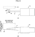
- Fig. 8 is a schematic diagram illustrating the swing-scraping burr removal device disclosed in Patent Literature 1.
- Fig. 8(A) is a side view
- Fig. 8(B) is a plan view.
- Fig. 8 illustrates a cast steel part 20 (slab) as an object from which burrs are to be removed.
- the burr removal device 1A disclosed in Patent Literature 1 includes a disc-shaped deburring blade 3 that removes burrs; a blade seat 4 that serves as a seat for the deburring blade 3; a blade seat support base 5 that supports the blade seat 4; an arm 6 having the blade seat support base 5 at a distal end thereof; and an arm vibration elevation drive unit 7.
- the arm vibration elevation drive unit 7 is a device for moving the arm 6 upward and downward, causing the arm 6 to extend and contract, and vibrating the arm 6 in front-back and/or left-right directions (directions along a plane in contact with a lower edge line of a fusion-cut surface of a cast steel part or a rolled steel part).
- the arm vibration elevation drive unit 7 is generally installed adjacent to a cast part conveyance line, and the arm 6 is generally disposed between conveying rollers of the cast part conveyance line.
- the cast steel part 20 or the rolled steel sheet is disposed such that an end surface thereof is positioned directly above the deburring blade 3.
- the arm vibration elevation drive unit 7 causes the deburring blade 3 to extend/contract and move upward so that the deburring blade 3 comes into contact with a lower surface of the cast steel part 20 or the rolled steel sheet.
- the deburring blade 3 that is in contact with the lower surface of the cast steel part 20 or the rolled steel sheet is vibrated along the plane in contact with the lower edge line of the fusion-cut surface of the cast steel part or the rolled steel part to forcefully scrape off the burrs.
- the deburring blade 3 wears and it becomes more difficult to remove the burrs due to, for example, rounded edges. Therefore, the deburring blade 3 needs to be replaced after being used a predetermined number of times.
- Fig. 9 illustrates the structure of a distal end portion of the arm of the burr removal device 1A disclosed in Patent Literature 1.
- the deburring blade 3 has recesses 3a in an upper surface thereof, and a bolt 16 and a bolt 17 are disposed in the recesses 3a.
- the bolt 16 and the bolt 17 extend through the deburring blade 3 and the blade seat 4, and also extend through bolt holes in a bottom plate 5a of the blade seat support base 5.
- the bolt 16 and the bolt 17, which extend through the bottom plate 5a are fastened to a nut 18 and a nut 19, respectively, on a lower surface of the bottom plate 5a.
- the blade seat 4 is an assembly including a base seat 8, a fitting member 14, and a fitting member 15.
- the fitting member 14 and the fitting member 15 form a fitting unit 9 that is fitted to the blade seat support base 5.
- the deburring blade 3 and the blade seat 4 are fixed to the blade seat support base 5 by the bolts 16 and 17 and the nuts 18 and 19. Therefore, to replace the deburring blade 3, it is necessary to loosen and remove the nuts 18 and 19 and pull out the bolts 16 and 17.
- the temperature of the deburring blade 3 may exceed, for example, about 400°C. Therefore, to replace the deburring blade 3, it is necessary to cool the deburring blade 3 (about 10 minutes), remove the bolts (about 25 minutes), remove the deburring blade 3 and attach another deburring blade 3 (about 5 minutes), and fasten the bolts (about 5 minutes). Thus, the replacement takes about 45 minutes. During this time, the casting operation of the continuous casting machine needs to be stopped. In other words, the productivity of the continuous casting machine is reduced.
- the replacement of the deburring blade 3 is carried out by removing the bolts 16 and 17 and assembling the deburring blade 3 and the blade seat 4 on-site at the location between the conveying rollers of the cast part conveyance line. Therefore, the work environment is not favorable. For example, the work space is small, and the ambient temperature is high because surrounding equipment is heated by the high-temperature cast part. In addition, since the deburring blade 3 is manually replaced, there is a risk of an accident such as pinching of a hand or a finger.
- the gist of the present invention for achieving the above-described objects are as follows:
- the deburring blade and the blade seat are integrated together, and the fitting unit of the blade seat can be inserted into and removed from the hollow space in the blade seat support base. Accordingly, the deburring blade and the blade seat can be assembled off-line.
- the deburring blade can be disposed at a predetermined position simply by inserting the deburring blade and the blade seat that are integrated together into the hollow space in the blade seat support base.
- replacement of the deburring blade is completed by removing the deburring blade and the blade seat that are integrated together and that have been used from the hollow space in the blade seat support base and then inserting another deburring blade and another blade seat that are assembled in advance into the hollow space in the blade seat support base.
- the deburring blade can be replaced in a short time.
- Fig. 1 is a schematic diagram illustrating a burr removal device for cast steel parts or rolled steel parts according to the present invention, wherein Fig. 1(A) is a side view and Fig. 1(B) is a plan view.
- Fig. 1 illustrates a cast steel part 20 (slab) as an object from which burrs are to be removed.
- a burr removal device 1 for cast steel parts or rolled steel parts according to the present invention basically has a structure similar to that of the swing-scraping burr removal device 1A according to Patent Literature 1 illustrated in Figs. 8 and 9 , but differs from the burr removal device 1A in that a blade seat support base 5 thereof has a hollow cylindrical shape. In other words, the blade seat support base 5 does not include the bottom plate 5a illustrated in Fig. 9 .
- the burr removal device 1 according to the present invention includes a disc-shaped deburring blade 3 and a blade seat 4 that are integrated together.
- a fitting unit 9, which is a lower portion of the blade seat 4 is inserted into a hollow space in the blade seat support base 5.
- the deburring blade 3 is mounted on a distal end portion of an arm 6 at a predetermined position.
- the burr removal device 1 for cast steel parts or rolled steel parts includes the disc-shaped deburring blade 3 that removes burrs; the blade seat 4 that is disposed in contact with a lower surface of the deburring blade 3 and that serves as a seat for the deburring blade 3; the blade seat support base 5 that supports the blade seat 4; the arm 6 having the blade seat support base 5 at the distal end thereof; and an arm vibration elevation drive unit 7 that moves the arm 6 upward and downward, causes the arm 6 to extend and contract, and vibrates the arm 6 in front-back and/or left-right directions, that is, along a plane in contact with a lower edge line of a fusion-cut surface of the cast steel part 20 or a rolled steel sheet.
- the assembly including the deburring blade 3 and the blade seat 4 that are integrated together is referred to also as a "blade unit”.
- reference sign 2 denotes the "blade unit".
- Fig. 2 illustrates the schematic structure of the blade unit 2 according to the first embodiment of the present invention.
- the blade unit 2 illustrated in Fig. 2 is structured such that the blade seat 4 is an assembly of three members, which are a base seat 8, a first fitting member 10, and a second fitting member 11.
- the first fitting member 10 and the second fitting member 11 of the blade seat 4 form a fitting unit 9 that is inserted in the hollow space in the blade seat support base 5.
- the blade unit 2 is structured such that the second fitting member 11, the first fitting member 10, the base seat 8, and the deburring blade 3 are stacked in that order in the direction from bottom to top.
- a bolt 16 and a bolt 17, which extend through the deburring blade 3, the base seat 8, the first fitting member 10, and the second fitting member 11, are disposed in recesses 3a formed in an upper surface of the deburring blade 3.
- a nut 18 and a nut 19 are fastened to the bolt 16 and the bolt 17, respectively, on a lower surface of the second fitting member 11.
- the deburring blade 3 and the blade seat 4 including the fitting unit 9 are fastened together by the bolts 16 and 17 and the nuts 18 and 19, and are thereby integrated together to form the blade unit 2.
- the first fitting member 10 and the second fitting member 11 have cylindrical shapes.
- Fig. 3 is a schematic diagram illustrating the state in which the blade unit 2 is inserted in the hollow space in the blade seat support base 5.
- the base seat 8 included in the blade seat 4 illustrated in Fig. 3 has a circular bottom surface, and the diameter of the bottom surface of the base seat 8 is greater than the inside diameter of the blade seat support base 5 (diameter of the hollow space). Therefore, the blade unit 2 is mounted on the blade seat support base 5 in a state such that the base seat 8 is placed on the upper edge of the blade seat support base 5. In this state, the fitting unit 9 of the blade seat 4 is inserted in the hollow space in the blade seat support base 5.
- the diameter of the first fitting member 10 and the diameter of the second fitting member 11 are less than the inside diameter of the blade seat support base 5 (diameter of the hollow space). Therefore, the first fitting member 10 and the second fitting member 11 can be easily inserted into the hollow space in the blade seat support base 5, and can be easily removed from the hollow space in the blade seat support base 5. In other words, the blade unit 2 can be easily inserted into and removed from the hollow space in the blade seat support base 5.
- the fitting unit 9 cannot be easily removed from the hollow space in the blade seat support base 5 due to thermal expansion during operation.
- the differences between the diameter of the first fitting member 10 and the inside diameter of the blade seat support base 5 (diameter of the hollow space) and between the diameter of the second fitting member 11 and the inside diameter of the blade seat support base 5 (diameter of the hollow space) are preferably greater than or equal to 7 mm.
- the diameter of the first fitting member 10 and the diameter of the second fitting member 11 are preferably set in accordance with the inside diameter of the blade seat support base 5 (diameter of the hollow space) so that the above-described differences are greater than or equal to 7 mm.
- the diameter of the first fitting member 10 and the diameter of the second fitting member 11 are, of course, less than the inside diameter of the blade seat support base 5 (diameter of the hollow space).
- the deburring blade 3 may move in the hollow space in the blade seat support base 5 due to reaction force generated in response to removal of the burrs, and stability of the operation of removing the burrs may be reduced. Therefore, the difference between the inside diameter of the blade seat support base 5 (diameter of the hollow space) and at least one of the diameter of the first fitting member 10 and the diameter of the second fitting member 11 is preferably less than or equal to 15 mm.
- the diameter of the first fitting member 10 and the diameter of the second fitting member 11 are preferably set in accordance with the inside diameter of the blade seat support base 5 (diameter of the hollow space) so that the above-described difference is less than or equal to 15 mm.
- the inventors of the present invention have confirmed that, when the difference between the inside diameter of the blade seat support base 5 (diameter of the hollow space) and at least one of the diameter of the first fitting member 10 and the diameter of the second fitting member 11 is less than or equal to 15 mm, the deburring blade 3 removes the burrs while moving substantially in synchronization with the movement of the arm 6, and stability of the operation of removing the burrs can be improved.
- the base seat 8 may be shaped such that the maximum outer dimension of at least a portion thereof is greater than the inside diameter of the blade seat support base 5, so that the base seat 8 does not pass through the hollow space in the blade seat support base 5 and is mounted on the blade seat support base 5.
- Fig. 4 is a schematic perspective view of the blade unit 2A according to the second embodiment
- Fig. 5 is a schematic diagram illustrating the state in which the blade unit 2A according to the second embodiment is inserted in the hollow space in the blade seat support base 5.
- the blade unit 2A includes a third fitting member 12 instead of the first fitting member 10 of the blade unit 2 and a fourth fitting member 13 instead of the second fitting member 11 of the blade unit 2.
- the blade unit 2A of the second embodiment is structured such that the third fitting member 12 and the fourth fitting member 13 form a fitting unit 9.
- the third fitting member 12 and the fourth fitting member 13 are elliptic cylindrical members having elliptical horizontal cross sections.
- the third fitting member 12 and the fourth fitting member 13 are oriented so that the major axis of the elliptical cross section of the third fitting member 12 and the major axis of the elliptical cross section of the fourth fitting member 13 are orthogonal to each other.
- the lengths of the major axes of the third fitting member 12 and the fourth fitting member 13 are preferably set as follows: either the difference between the length of the major axis of the elliptical cross section of the third fitting member 12 and the inside diameter of the blade seat support base 5 (diameter of the hollow space) is greater than or equal to 7 mm and less than or equal to 15 mm, or the difference between the length of the major axis of the elliptical cross section of the fourth fitting member 13 and the inside diameter of the blade seat support base 5 (diameter of the hollow space) is greater than or equal to 7 mm and less than or equal to 15 mm.
- the length of the major axis of the elliptical cross section of the third fitting member 12 and the length of the major axis of the elliptical cross section of the fourth fitting member 13 are, of course, less than the inside diameter of the blade seat support base 5 (diameter of the hollow space).
- the cast steel part 20 or the rolled steel sheet is disposed such that an end surface thereof is positioned directly above the deburring blade 3.
- the arm vibration elevation drive unit 7 causes the deburring blade 3 to extend/contract and move upward so that the deburring blade 3 comes into contact with a lower surface of the cast steel part 20 or the rolled steel sheet.
- the deburring blade 3 that is in contact with the lower surface of the cast steel part 20 or the rolled steel sheet is vibrated in the front-back and/or left-right directions to forcefully scrape off the burrs.
- the deburring blade 3 is vibrated along the plane in contact with the lower edge line of the fusion-cut surface of the cast steel part 20 or the rolled steel sheet to forcefully scrape off the burrs.
- Figs. 6 and 7 illustrate an optimum method for carrying the blade unit 2 or the blade unit 2A.
- Figs. 6 and 7 illustrate an example in which the blade unit 2A is carried.
- a lower end portion of a lifting tool 21, which has an open end is engaged with the lower end of the deburring blade 3 of the blade unit 2 or the blade unit 2A, and then the open end of the lifting tool 21 is closed so that the lifting tool 21 has an annular shape.
- a hook 22 of, for example, a hoist or a crane is engaged with a lifting bail 21a of the lifting tool 21 having the annular shape, and the blade unit 2 or the blade unit 2A is lifted and transported by the hoist or the crane.
- the blade unit 2 or the blade unit 2A that is inserted in the hollow space in the blade seat support base 5 and that has been used is lifted and removed by a hoist or a crane.
- another blade unit 2 or another blade unit 2A that is assembled in advance and stored in a storage is lifted by the hoist or the crane and conveyed to a position directly above the blade seat support base 5, and is lowered by the hoist or the crane, so that the blade unit 2 or the blade unit 2A is inserted into the hollow space in the blade seat support base 5.
- a method for manufacturing cast steel parts or rolled steel parts of the present invention includes removing burrs from the cast steel part 20 formed by continuous casting or a rolled steel part formed by hot rolling by using the above-described burr removal device 1, thereby manufacturing the cast steel part 20 or the rolled steel part.
- the deburring blade 3 and the blade seat 4 are integrated together, and the fitting unit 9 of the blade seat 4 can be inserted into and removed from the hollow space in the blade seat support base 5. Accordingly, the deburring blade 3 and the blade seat 4 can be assembled off-line. In addition, the deburring blade 3 can be disposed at a predetermined position simply by inserting the deburring blade 3 and the blade seat 4 that are integrated together into the hollow space in the blade seat support base 5.
- replacement of the deburring blade 3 is completed by removing the deburring blade 3 and the blade seat 4 that are integrated together and that have been used from the hollow space in the blade seat support base 5 and then inserting another deburring blade 3 and another blade seat 4 that are assembled in advance into the hollow space in the blade seat support base 5.
- the deburring blade 3 can be replaced in a short time.
- the present invention was applied to a burr removal device 1 installed on a cast part conveyance line of a slab continuous casting machine that performs continuous casting to produce a slab having a width of 700 to 1600 mm and a thickness of 220 mm.
- the burr removal device 1 illustrated in Fig. 1 was structured such that the diameter of the upper surface of the deburring blade 3 was 180 mm, that the inside diameter of the blade seat support base 5 (diameter of the hollow space) was 140 mm, and that the height of the blade seat support base 5 was 150 mm.
- This blade seat support base 5 was used together with the blade unit 2 illustrated in Fig. 3 , in which the diameter of the second fitting member 11 was 133 mm (diameter of the first fitting member 10 was 90 mm), and the blade unit 2A illustrated in Fig.
Landscapes
- Engineering & Computer Science (AREA)
- Mechanical Engineering (AREA)
- Physics & Mathematics (AREA)
- Optics & Photonics (AREA)
- Milling, Broaching, Filing, Reaming, And Others (AREA)
- Metal Rolling (AREA)
Abstract
Description
- The present invention relates to a burr removal device for removing burrs formed by fusing cast steel parts or rolled steel parts. The present invention also relates to a method for manufacturing cast steel parts or rolled steel parts by removing burrs by using the burr removal device.
- Cast steel parts formed by continuous casting and rolled steel sheets formed by hot rolling are generally cut into predetermined lengths by using a gas cutting machine having a high cutting efficiency. The gas cutting machine cuts the cast steel parts or the rolled steel sheets using oxygen gas or mixed gas containing oxygen gas and propane gas (fusion cutting). Accordingly, burrs containing melted iron (hereinafter also referred to simply as "burrs") remain at the bottom of cut surfaces formed by the gas cutting machine. When steel slabs are heated without removing the burrs and then hot rolled into steel sheets, surface defects called "scabs" are formed at the leading and trailing ends of the steel sheets manufactured by hot rolling. This leads to a reduction in the yield of the steel sheets. Accordingly, various devices for removing the burrs have been proposed.
- For example,
Patent Literature 1 proposes a swing-scraping burr removal device including a disc-shaped deburring blade that scrapes off melted burrs and an arm that swings the deburring blade in front-back and left-right directions.Fig. 8 is a schematic diagram illustrating the swing-scraping burr removal device disclosed inPatent Literature 1.Fig. 8(A) is a side view, andFig. 8(B) is a plan view.Fig. 8 illustrates a cast steel part 20 (slab) as an object from which burrs are to be removed. - As illustrated in
Fig. 8 , theburr removal device 1A disclosed inPatent Literature 1 includes a disc-shaped deburring blade 3 that removes burrs; ablade seat 4 that serves as a seat for thedeburring blade 3; a bladeseat support base 5 that supports theblade seat 4; anarm 6 having the bladeseat support base 5 at a distal end thereof; and an arm vibrationelevation drive unit 7. The arm vibrationelevation drive unit 7 is a device for moving thearm 6 upward and downward, causing thearm 6 to extend and contract, and vibrating thearm 6 in front-back and/or left-right directions (directions along a plane in contact with a lower edge line of a fusion-cut surface of a cast steel part or a rolled steel part). When theburr removal device 1A is applied to a continuous casting facility, the arm vibrationelevation drive unit 7 is generally installed adjacent to a cast part conveyance line, and thearm 6 is generally disposed between conveying rollers of the cast part conveyance line. - A method for removing burrs by using the swing-scraping
burr removal device 1A will now be described. First, thecast steel part 20 or the rolled steel sheet is disposed such that an end surface thereof is positioned directly above the deburringblade 3. Next, the arm vibrationelevation drive unit 7 causes the deburringblade 3 to extend/contract and move upward so that thedeburring blade 3 comes into contact with a lower surface of thecast steel part 20 or the rolled steel sheet. After that, thedeburring blade 3 that is in contact with the lower surface of thecast steel part 20 or the rolled steel sheet is vibrated along the plane in contact with the lower edge line of the fusion-cut surface of the cast steel part or the rolled steel part to forcefully scrape off the burrs. - As the number of times the
deburring blade 3 is used increases, thedeburring blade 3 wears and it becomes more difficult to remove the burrs due to, for example, rounded edges. Therefore, thedeburring blade 3 needs to be replaced after being used a predetermined number of times. -
Fig. 9 illustrates the structure of a distal end portion of the arm of theburr removal device 1A disclosed inPatent Literature 1. Thedeburring blade 3 hasrecesses 3a in an upper surface thereof, and abolt 16 and abolt 17 are disposed in therecesses 3a. Thebolt 16 and thebolt 17 extend through thedeburring blade 3 and theblade seat 4, and also extend through bolt holes in abottom plate 5a of the bladeseat support base 5. Thebolt 16 and thebolt 17, which extend through thebottom plate 5a, are fastened to anut 18 and anut 19, respectively, on a lower surface of thebottom plate 5a. Theblade seat 4 is an assembly including abase seat 8, afitting member 14, and afitting member 15. Thefitting member 14 and thefitting member 15 form afitting unit 9 that is fitted to the bladeseat support base 5. - Thus, the
deburring blade 3 and theblade seat 4 are fixed to the bladeseat support base 5 by thebolts nuts deburring blade 3, it is necessary to loosen and remove thenuts bolts - When the
deburring blade 3 is used to remove burrs from a cast steel part immediately after the cast steel part is formed by a continuous casting machine, the temperature of the deburringblade 3 may exceed, for example, about 400°C. Therefore, to replace thedeburring blade 3, it is necessary to cool the deburring blade 3 (about 10 minutes), remove the bolts (about 25 minutes), remove the deburringblade 3 and attach another deburring blade 3 (about 5 minutes), and fasten the bolts (about 5 minutes). Thus, the replacement takes about 45 minutes. During this time, the casting operation of the continuous casting machine needs to be stopped. In other words, the productivity of the continuous casting machine is reduced. - The replacement of the deburring
blade 3 is carried out by removing thebolts deburring blade 3 and theblade seat 4 on-site at the location between the conveying rollers of the cast part conveyance line. Therefore, the work environment is not favorable. For example, the work space is small, and the ambient temperature is high because surrounding equipment is heated by the high-temperature cast part. In addition, since thedeburring blade 3 is manually replaced, there is a risk of an accident such as pinching of a hand or a finger. - PTL 1: West
German Patent No. 3515111 - The present invention has been made in light of the above-described circumstances, and an object of the present invention is to provide a burr removal device for cast steel parts or rolled steel parts with which it is not necessary to remove the
bolt 16 and thebolt 17 and assemble thedeburring blade 3 and theblade seat 4 on-site at the location between the conveying rollers, and with which thedeburring blade 3 can be replaced in a short time. Another object of the present invention is to provide a method for manufacturing cast steel parts or rolled steel parts by removing burrs by using the burr removal device. - The gist of the present invention for achieving the above-described objects are as follows:
- [1] A burr removal device for removing burrs formed by fusing cast steel parts or rolled steel parts, the burr removal device including:
- a deburring blade that is disc-shaped and that removes burrs;
- a blade seat that is disposed in contact with a lower surface of the deburring blade and that serves as a seat for the deburring blade;
- a blade seat support base that supports the blade seat;
- an arm having the blade seat support base at a distal end thereof; and
- an arm vibration elevation drive unit that moves the arm upward and downward, causes the arm to extend and contract, and vibrates the arm along a plane in contact with a lower edge line of a fusion-cut surface of a cast steel part or a rolled steel part,
- wherein the blade seat support base has a hollow cylindrical shape, and at least a portion of the blade seat has an outer dimension greater than an inside diameter of the blade seat support base (diameter of a hollow space),
- wherein a lower portion of the blade seat serves as a fitting unit that is inserted in the hollow space in the blade seat support base,
- wherein the blade seat including the fitting unit is integrated with the deburring blade by a bolt that extends through the blade seat and the deburring blade and a nut that is fastened to the bolt, and
- wherein the fitting unit is capable of being inserted into and removed from the hollow space in the blade seat support base, and the deburring blade is disposed at a predetermined position when the fitting unit is inserted in the hollow space in the blade seat support base.
- [2] The burr removal device for cast steel parts or rolled steel parts according to [1], wherein a difference between a maximum outer dimension of the fitting unit and the inside diameter of the blade seat support base (diameter of the hollow space) is greater than or equal to 7 mm.
- [3] A method for manufacturing cast steel parts or rolled steel parts, the method including:
- removing burrs from a cast steel part formed by continuous casting or from a rolled steel part formed by hot rolling by using the burr removal device for cast steel parts or rolled steel parts according to [1] or [2], thereby manufacturing a cast steel part or a rolled steel part. Advantageous Effects of Invention
- According to the present invention, the deburring blade and the blade seat are integrated together, and the fitting unit of the blade seat can be inserted into and removed from the hollow space in the blade seat support base. Accordingly, the deburring blade and the blade seat can be assembled off-line. In addition, the deburring blade can be disposed at a predetermined position simply by inserting the deburring blade and the blade seat that are integrated together into the hollow space in the blade seat support base.
- In addition, according to the present invention, replacement of the deburring blade is completed by removing the deburring blade and the blade seat that are integrated together and that have been used from the hollow space in the blade seat support base and then inserting another deburring blade and another blade seat that are assembled in advance into the hollow space in the blade seat support base. Thus, the deburring blade can be replaced in a short time.
-
- [
Fig. 1] Fig. 1 is a schematic diagram illustrating a burr removal device for cast steel parts or rolled steel parts according to the present invention, whereinFig. 1(A) is a side view andFig. 1(B) is a plan view. - [
Fig. 2] Fig. 2 is a schematic diagram illustrating the schematic structure of a blade unit according to a first embodiment. - [
Fig. 3] Fig. 3 is a schematic diagram illustrating the state in which the blade unit according to the first embodiment is inserted in a hollow space in a blade seat support base. - [
Fig. 4] Fig. 4 is a schematic perspective view of a blade unit according to a second embodiment. - [
Fig. 5] Fig. 5 is a schematic diagram illustrating the state in which the blade unit according to the second embodiment is inserted in the hollow space in the blade seat support base. - [
Fig. 6] Fig. 6 is a schematic diagram illustrating an optimum method for carrying the blade units according to the first embodiment and the second embodiment. - [
Fig. 7] Fig. 7 is a schematic diagram illustrating the optimum method for carrying the blade units according to the first embodiment and the second embodiment. - [
Fig. 8] Fig. 8 is a schematic diagram illustrating a swing-scraping burr removal device disclosed inPatent Literature 1, whereinFig. 8(A) is a side view andFig. 8(B) is a plan view. - [
Fig. 9] Fig. 9 is a schematic diagram illustrating the structure of a distal end portion of an arm of the burr removal device disclosed inPatent Literature 1. Description of Embodiments - The present invention will now be described with reference to the accompanying drawings.
Fig. 1 is a schematic diagram illustrating a burr removal device for cast steel parts or rolled steel parts according to the present invention, whereinFig. 1(A) is a side view andFig. 1(B) is a plan view.Fig. 1 illustrates a cast steel part 20 (slab) as an object from which burrs are to be removed. - A
burr removal device 1 for cast steel parts or rolled steel parts according to the present invention basically has a structure similar to that of the swing-scrapingburr removal device 1A according toPatent Literature 1 illustrated inFigs. 8 and9 , but differs from theburr removal device 1A in that a bladeseat support base 5 thereof has a hollow cylindrical shape. In other words, the bladeseat support base 5 does not include thebottom plate 5a illustrated inFig. 9 . Theburr removal device 1 according to the present invention includes a disc-shapeddeburring blade 3 and ablade seat 4 that are integrated together. Afitting unit 9, which is a lower portion of theblade seat 4, is inserted into a hollow space in the bladeseat support base 5. Thus, thedeburring blade 3 is mounted on a distal end portion of anarm 6 at a predetermined position. - As illustrated in
Fig. 1 , theburr removal device 1 for cast steel parts or rolled steel parts according to the present invention includes the disc-shapeddeburring blade 3 that removes burrs; theblade seat 4 that is disposed in contact with a lower surface of thedeburring blade 3 and that serves as a seat for thedeburring blade 3; the bladeseat support base 5 that supports theblade seat 4; thearm 6 having the bladeseat support base 5 at the distal end thereof; and an arm vibrationelevation drive unit 7 that moves thearm 6 upward and downward, causes thearm 6 to extend and contract, and vibrates thearm 6 in front-back and/or left-right directions, that is, along a plane in contact with a lower edge line of a fusion-cut surface of thecast steel part 20 or a rolled steel sheet. In this specification, the assembly including thedeburring blade 3 and theblade seat 4 that are integrated together is referred to also as a "blade unit". InFig. 1 ,reference sign 2 denotes the "blade unit". -
Fig. 2 illustrates the schematic structure of theblade unit 2 according to the first embodiment of the present invention. Theblade unit 2 illustrated inFig. 2 is structured such that theblade seat 4 is an assembly of three members, which are abase seat 8, a firstfitting member 10, and a secondfitting member 11. The firstfitting member 10 and the secondfitting member 11 of theblade seat 4 form afitting unit 9 that is inserted in the hollow space in the bladeseat support base 5. Theblade unit 2 is structured such that the secondfitting member 11, the firstfitting member 10, thebase seat 8, and thedeburring blade 3 are stacked in that order in the direction from bottom to top. Abolt 16 and abolt 17, which extend through thedeburring blade 3, thebase seat 8, the firstfitting member 10, and the secondfitting member 11, are disposed inrecesses 3a formed in an upper surface of thedeburring blade 3. Anut 18 and anut 19 are fastened to thebolt 16 and thebolt 17, respectively, on a lower surface of the secondfitting member 11. Thus, thedeburring blade 3 and theblade seat 4 including thefitting unit 9 are fastened together by thebolts blade unit 2. The firstfitting member 10 and the secondfitting member 11 have cylindrical shapes. -
Fig. 3 is a schematic diagram illustrating the state in which theblade unit 2 is inserted in the hollow space in the bladeseat support base 5. Thebase seat 8 included in theblade seat 4 illustrated inFig. 3 has a circular bottom surface, and the diameter of the bottom surface of thebase seat 8 is greater than the inside diameter of the blade seat support base 5 (diameter of the hollow space). Therefore, theblade unit 2 is mounted on the bladeseat support base 5 in a state such that thebase seat 8 is placed on the upper edge of the bladeseat support base 5. In this state, thefitting unit 9 of theblade seat 4 is inserted in the hollow space in the bladeseat support base 5. - The diameter of the first
fitting member 10 and the diameter of the secondfitting member 11 are less than the inside diameter of the blade seat support base 5 (diameter of the hollow space). Therefore, the firstfitting member 10 and the secondfitting member 11 can be easily inserted into the hollow space in the bladeseat support base 5, and can be easily removed from the hollow space in the bladeseat support base 5. In other words, theblade unit 2 can be easily inserted into and removed from the hollow space in the bladeseat support base 5. - When the differences between the diameter of the first
fitting member 10 and the inside diameter of the blade seat support base 5 (diameter of the hollow space) and between the diameter of the secondfitting member 11 and the inside diameter of the blade seat support base 5 (diameter of the hollow space) are small, thefitting unit 9 cannot be easily removed from the hollow space in the bladeseat support base 5 due to thermal expansion during operation. To prevent this, the differences between the diameter of the firstfitting member 10 and the inside diameter of the blade seat support base 5 (diameter of the hollow space) and between the diameter of the secondfitting member 11 and the inside diameter of the blade seat support base 5 (diameter of the hollow space) are preferably greater than or equal to 7 mm. In other words, the diameter of the firstfitting member 10 and the diameter of the secondfitting member 11 are preferably set in accordance with the inside diameter of the blade seat support base 5 (diameter of the hollow space) so that the above-described differences are greater than or equal to 7 mm. The diameter of the firstfitting member 10 and the diameter of the secondfitting member 11 are, of course, less than the inside diameter of the blade seat support base 5 (diameter of the hollow space). - When the diameter of the first
fitting member 10 and the diameter of the secondfitting member 11 are too small relative to the inside diameter of the blade seat support base 5 (diameter of the hollow space), thedeburring blade 3 may move in the hollow space in the bladeseat support base 5 due to reaction force generated in response to removal of the burrs, and stability of the operation of removing the burrs may be reduced. Therefore, the difference between the inside diameter of the blade seat support base 5 (diameter of the hollow space) and at least one of the diameter of the firstfitting member 10 and the diameter of the secondfitting member 11 is preferably less than or equal to 15 mm. In other words, the diameter of the firstfitting member 10 and the diameter of the secondfitting member 11 are preferably set in accordance with the inside diameter of the blade seat support base 5 (diameter of the hollow space) so that the above-described difference is less than or equal to 15 mm. The inventors of the present invention have confirmed that, when the difference between the inside diameter of the blade seat support base 5 (diameter of the hollow space) and at least one of the diameter of the firstfitting member 10 and the diameter of the secondfitting member 11 is less than or equal to 15 mm, thedeburring blade 3 removes the burrs while moving substantially in synchronization with the movement of thearm 6, and stability of the operation of removing the burrs can be improved. - When the
base seat 8 does not have a circular cross section, thebase seat 8 may be shaped such that the maximum outer dimension of at least a portion thereof is greater than the inside diameter of the bladeseat support base 5, so that thebase seat 8 does not pass through the hollow space in the bladeseat support base 5 and is mounted on the bladeseat support base 5. - The structure of a
blade unit 2A according to a second embodiment of the present invention will now be described with reference toFigs. 4 and 5. Fig. 4 is a schematic perspective view of theblade unit 2A according to the second embodiment, andFig. 5 is a schematic diagram illustrating the state in which theblade unit 2A according to the second embodiment is inserted in the hollow space in the bladeseat support base 5. - The difference between the
blade unit 2A according to the second embodiment and theblade unit 2 according to first embodiment will now be described. Theblade unit 2A includes a thirdfitting member 12 instead of the firstfitting member 10 of theblade unit 2 and a fourthfitting member 13 instead of the secondfitting member 11 of theblade unit 2. In other words, theblade unit 2A of the second embodiment is structured such that the thirdfitting member 12 and the fourthfitting member 13 form afitting unit 9. - The third
fitting member 12 and the fourthfitting member 13 are elliptic cylindrical members having elliptical horizontal cross sections. The thirdfitting member 12 and the fourthfitting member 13 are oriented so that the major axis of the elliptical cross section of the thirdfitting member 12 and the major axis of the elliptical cross section of the fourthfitting member 13 are orthogonal to each other. In this case, the lengths of the major axes of the thirdfitting member 12 and the fourthfitting member 13 are preferably set as follows: either the difference between the length of the major axis of the elliptical cross section of the thirdfitting member 12 and the inside diameter of the blade seat support base 5 (diameter of the hollow space) is greater than or equal to 7 mm and less than or equal to 15 mm, or the difference between the length of the major axis of the elliptical cross section of the fourthfitting member 13 and the inside diameter of the blade seat support base 5 (diameter of the hollow space) is greater than or equal to 7 mm and less than or equal to 15 mm. The length of the major axis of the elliptical cross section of the thirdfitting member 12 and the length of the major axis of the elliptical cross section of the fourthfitting member 13 are, of course, less than the inside diameter of the blade seat support base 5 (diameter of the hollow space). - Other structures of the
blade unit 2A, which are the same as those of theblade unit 2 according to the first embodiment illustrated inFig. 2 , are denoted by the same reference signs as those of theblade unit 2 and description thereof is thus omitted. - A method for removing burrs by using the swing-scraping
burr removal device 1 according to the present invention will now be described. First, thecast steel part 20 or the rolled steel sheet is disposed such that an end surface thereof is positioned directly above thedeburring blade 3. Next, the arm vibrationelevation drive unit 7 causes thedeburring blade 3 to extend/contract and move upward so that thedeburring blade 3 comes into contact with a lower surface of thecast steel part 20 or the rolled steel sheet. After that, thedeburring blade 3 that is in contact with the lower surface of thecast steel part 20 or the rolled steel sheet is vibrated in the front-back and/or left-right directions to forcefully scrape off the burrs. In other words, thedeburring blade 3 is vibrated along the plane in contact with the lower edge line of the fusion-cut surface of thecast steel part 20 or the rolled steel sheet to forcefully scrape off the burrs. -
Figs. 6 and 7 illustrate an optimum method for carrying theblade unit 2 or theblade unit 2A.Figs. 6 and 7 illustrate an example in which theblade unit 2A is carried. As illustrated inFig. 6 , a lower end portion of alifting tool 21, which has an open end, is engaged with the lower end of thedeburring blade 3 of theblade unit 2 or theblade unit 2A, and then the open end of thelifting tool 21 is closed so that thelifting tool 21 has an annular shape. After that, as illustrated inFig. 7 , ahook 22 of, for example, a hoist or a crane is engaged with a liftingbail 21a of thelifting tool 21 having the annular shape, and theblade unit 2 or theblade unit 2A is lifted and transported by the hoist or the crane. - To replace the
deburring blade 3, first, theblade unit 2 or theblade unit 2A that is inserted in the hollow space in the bladeseat support base 5 and that has been used is lifted and removed by a hoist or a crane. After that, anotherblade unit 2 or anotherblade unit 2A that is assembled in advance and stored in a storage is lifted by the hoist or the crane and conveyed to a position directly above the bladeseat support base 5, and is lowered by the hoist or the crane, so that theblade unit 2 or theblade unit 2A is inserted into the hollow space in the bladeseat support base 5. - A method for manufacturing cast steel parts or rolled steel parts of the present invention includes removing burrs from the
cast steel part 20 formed by continuous casting or a rolled steel part formed by hot rolling by using the above-describedburr removal device 1, thereby manufacturing thecast steel part 20 or the rolled steel part. - As described above, according to the present invention, the
deburring blade 3 and theblade seat 4 are integrated together, and thefitting unit 9 of theblade seat 4 can be inserted into and removed from the hollow space in the bladeseat support base 5. Accordingly, thedeburring blade 3 and theblade seat 4 can be assembled off-line. In addition, thedeburring blade 3 can be disposed at a predetermined position simply by inserting thedeburring blade 3 and theblade seat 4 that are integrated together into the hollow space in the bladeseat support base 5. - In addition, according to the present invention, replacement of the
deburring blade 3 is completed by removing thedeburring blade 3 and theblade seat 4 that are integrated together and that have been used from the hollow space in the bladeseat support base 5 and then inserting anotherdeburring blade 3 and anotherblade seat 4 that are assembled in advance into the hollow space in the bladeseat support base 5. Thus, thedeburring blade 3 can be replaced in a short time. - The present invention was applied to a
burr removal device 1 installed on a cast part conveyance line of a slab continuous casting machine that performs continuous casting to produce a slab having a width of 700 to 1600 mm and a thickness of 220 mm. - The
burr removal device 1 illustrated inFig. 1 was structured such that the diameter of the upper surface of thedeburring blade 3 was 180 mm, that the inside diameter of the blade seat support base 5 (diameter of the hollow space) was 140 mm, and that the height of the bladeseat support base 5 was 150 mm. This bladeseat support base 5 was used together with theblade unit 2 illustrated inFig. 3 , in which the diameter of the secondfitting member 11 was 133 mm (diameter of the firstfitting member 10 was 90 mm), and theblade unit 2A illustrated inFig. 5 , in which the length of the major axis of the elliptical cross section of the thirdfitting member 12 and the length of the major axis of the elliptical cross section of the fourthfitting member 13 were 130 mm. Under these conditions, a test for removing burrs was performed. The quality of the operation of removing burrs was evaluated based on the occurrence of scabs due to burrs on a steel sheet obtained by hot rolling the slab. - As a result, both when the
blade unit 2 illustrated inFig. 3 was used and when theblade unit 2A illustrated inFig. 5 was used, the occurrence of scabs due to burrs on the steel sheet obtained by hot rolling was similar to that when theburr removal device 1A according to the related art illustrated inFig. 8 was used. The time required to replace thedeburring blade 3 was 5 minutes, which is shorter by 40 minutes than the time required according to the related art. -
- 1
- burr removal device
- 1A
- burr removal device disclosed in
Patent Literature 1 - 2
- blade unit
- 3
- deburring blade
- 3a
- recess
- 4
- blade seat
- 5
- blade seat support base
- 6
- arm
- 7
- arm vibration elevation drive unit
- 8
- base seat
- 9
- fitting unit
- 10
- first fitting member
- 11
- second fitting member
- 12
- third fitting member
- 13
- fourth fitting member
- 14
- fitting member
- 15
- fitting member
- 16
- bolt
- 17
- bolt
- 18
- nut
- 19
- nut
- 20
- cast steel part
- 21
- lifting tool
- 22
- hook
Claims (3)
- A burr removal device for removing burrs formed by fusing cast steel parts or rolled steel parts, the burr removal device comprising: a deburring blade that is disc-shaped and that removes burrs;a blade seat that is disposed in contact with a lower surface of the deburring blade and that serves as a seat for the deburring blade;a blade seat support base that supports the blade seat; an arm having the blade seat support base at a distal end thereof; andan arm vibration elevation drive unit that moves the arm upward and downward, causes the arm to extend and contract, and vibrates the arm along a plane in contact with a lower edge line of a fusion-cut surface of a cast steel part or a rolled steel part,wherein the blade seat support base has a hollow cylindrical shape, and at least a portion of the blade seat has an outer dimension greater than an inside diameter of the blade seat support base (diameter of a hollow space),wherein a lower portion of the blade seat serves as a fitting unit that is inserted in the hollow space in the blade seat support base,wherein the blade seat including the fitting unit is integrated with the deburring blade by a bolt that extends through the blade seat and the deburring blade and a nut that is fastened to the bolt, andwherein the fitting unit is capable of being inserted into and removed from the hollow space in the blade seat support base, and the deburring blade is disposed at a predetermined position when the fitting unit is inserted in the hollow space in the blade seat support base.
- The burr removal device for cast steel parts or rolled steel parts according to Claim 1,
wherein a difference between a maximum outer dimension of the fitting unit and the inside diameter of the blade seat support base (diameter of the hollow space) is greater than or equal to 7 mm. - A method for manufacturing cast steel parts or rolled steel parts, the method comprising:removing burrs formed by fusing from a cast steel part formed by continuous casting or from a rolled steel part formed by hot rolling by using the burr removal device for cast steel parts or rolled steel parts according to Claim 1 or 2, thereby manufacturing a cast steel part or a rolled steel part.
Applications Claiming Priority (2)
| Application Number | Priority Date | Filing Date | Title |
|---|---|---|---|
| JP2018207860 | 2018-11-05 | ||
| PCT/JP2019/042459 WO2020095773A1 (en) | 2018-11-05 | 2019-10-30 | Melted burr removal device for cast steel parts or rolled steel parts, and method for manufacturing cast steel parts or rolled steel parts |
Publications (3)
| Publication Number | Publication Date |
|---|---|
| EP3878573A1 true EP3878573A1 (en) | 2021-09-15 |
| EP3878573A4 EP3878573A4 (en) | 2021-09-15 |
| EP3878573B1 EP3878573B1 (en) | 2023-07-12 |
Family
ID=70611842
Family Applications (1)
| Application Number | Title | Priority Date | Filing Date |
|---|---|---|---|
| EP19882448.4A Active EP3878573B1 (en) | 2018-11-05 | 2019-10-30 | Melted burr removal device for cast steel parts or rolled steel parts, and method for manufacturing cast steel parts or rolled steel parts |
Country Status (4)
| Country | Link |
|---|---|
| EP (1) | EP3878573B1 (en) |
| JP (1) | JP7010388B2 (en) |
| CN (1) | CN112955264A (en) |
| WO (1) | WO2020095773A1 (en) |
Family Cites Families (21)
| Publication number | Priority date | Publication date | Assignee | Title |
|---|---|---|---|---|
| CH620389A5 (en) * | 1977-07-11 | 1980-11-28 | Fischer Ag Georg | |
| US4376357A (en) * | 1980-05-21 | 1983-03-15 | Keighley Grinders (Machine Tools) Ltd. | Machine tools |
| DE3515111A1 (en) | 1985-04-26 | 1986-11-06 | Bwg Bergwerk- Und Walzwerk-Maschinenbau Gmbh, 4100 Duisburg | Method and apparatus for removing flame-cutting burrs from the flame-cut edges of metal parts, in particular slabs, blooms, billets or the like |
| EP0446256A4 (en) * | 1988-12-02 | 1991-09-25 | The Broken Hill Proprietary Company Limited | A deburrer assembly for the removal of burrs and other defects from the surface of castings |
| JPH03243261A (en) * | 1990-02-19 | 1991-10-30 | Kawasaki Steel Corp | Method for executing grinding cleaning for melt-cutting face in continuously cast slab |
| JP2629467B2 (en) * | 1991-03-12 | 1997-07-09 | 住友金属工業株式会社 | Grinding method of steel slab end face with rotary grinding wheel |
| JP3402772B2 (en) * | 1994-08-12 | 2003-05-06 | 大洋電産株式会社 | Brush sweep type cleaning device |
| JPH0871900A (en) * | 1994-09-07 | 1996-03-19 | Hino Motors Ltd | Device for deburring ring-shaped part |
| JPH10263773A (en) * | 1997-03-27 | 1998-10-06 | Kawasaki Steel Corp | Torch sag removal device for continuous cast slab |
| EP1943050B1 (en) * | 2005-10-14 | 2010-02-24 | P & L GmbH & Co. KG | Device for detachably clamping a tool on a spindle shaft of a machine-tool |
| KR101242307B1 (en) * | 2005-12-01 | 2013-03-11 | 미쓰보시 다이야몬도 고교 가부시키가이샤 | Tip holder installation |
| JP4843332B2 (en) * | 2006-02-20 | 2011-12-21 | 本田技研工業株式会社 | Deburring tool |
| KR100649745B1 (en) * | 2006-09-07 | 2006-11-29 | (주)삼우기계 | Billet cutting device |
| JP5086135B2 (en) * | 2008-03-06 | 2012-11-28 | 株式会社チップトン | Deburring brush |
| JP5064344B2 (en) * | 2008-09-25 | 2012-10-31 | 日本省力機械株式会社 | Robot system |
| CN201677091U (en) * | 2010-03-16 | 2010-12-22 | 新疆八一钢铁股份有限公司 | The Lifting Knife Rest of the Improved Scraper Type Slab Deburring Machine |
| JP5685775B2 (en) * | 2011-08-01 | 2015-03-18 | ステイト工業株式会社 | Brush and manufacturing method thereof |
| TWM476020U (en) * | 2013-10-24 | 2014-04-11 | Tct Global Ltd | Milling chuck structure of milling cutter processing machine and sleeve structure thereof |
| CN205254140U (en) * | 2015-12-22 | 2016-05-25 | 漳州升源机械工业有限公司 | Cutter and fixed knot construct with integral type connecting support |
| CN205798548U (en) * | 2016-06-01 | 2016-12-14 | 鞍钢重型机械有限责任公司 | Novel slab deburring |
| CN108044389B (en) * | 2017-12-12 | 2020-04-17 | 南通杰卡博工程机械有限公司 | Numerical control machine tool convenient for replacing cutter |
-
2019
- 2019-10-30 JP JP2020555991A patent/JP7010388B2/en active Active
- 2019-10-30 WO PCT/JP2019/042459 patent/WO2020095773A1/en not_active Ceased
- 2019-10-30 CN CN201980071154.0A patent/CN112955264A/en active Pending
- 2019-10-30 EP EP19882448.4A patent/EP3878573B1/en active Active
Also Published As
| Publication number | Publication date |
|---|---|
| WO2020095773A1 (en) | 2020-05-14 |
| EP3878573A4 (en) | 2021-09-15 |
| EP3878573B1 (en) | 2023-07-12 |
| JPWO2020095773A1 (en) | 2021-09-02 |
| JP7010388B2 (en) | 2022-01-26 |
| CN112955264A (en) | 2021-06-11 |
Similar Documents
| Publication | Publication Date | Title |
|---|---|---|
| US8367969B2 (en) | Support table frame for high speed laser blanking | |
| JP5974887B2 (en) | Method for producing seed for polycrystalline silicon production | |
| JP2002137930A (en) | Apparatus and method for separating a plate from a moving brittle sheet of material | |
| JP2017053003A (en) | Method for manufacturing metal member | |
| JP5910773B2 (en) | Cutting method of glass plate | |
| CN103302536A (en) | Tool tongs, tool changing device and tool magazine | |
| EP3878573A1 (en) | Melted burr removal device for cast steel parts or rolled steel parts, and method for manufacturing cast steel parts or rolled steel parts | |
| JP2015167987A (en) | Pull-up type continuous casting apparatus and pull-up type continuous casting method | |
| KR101917437B1 (en) | Jig and method for welding | |
| JP6145301B2 (en) | Method and apparatus for forming fracture start portion of connecting rod | |
| KR100628836B1 (en) | Lug cutting machine | |
| CN206527416U (en) | Numerical control cutting machine moulding bed support base | |
| JP5189416B2 (en) | Weir-folding method for separating cast products and scrap materials from the plan, and the weir-folding device | |
| JP2009190138A (en) | Blade mounting jig set and mounting method | |
| JP2016175123A (en) | Manufacturing method for turbine blade material | |
| JP6020429B2 (en) | Steel plate suspension and steel plate suspension method | |
| JP5838916B2 (en) | Cutting device and method for removing upper blade holder in cutting device | |
| JP5196629B2 (en) | Substrate cutting method | |
| JP2018069419A (en) | Cutting machine, cutting support mechanism and cutting method using the same | |
| CN217122799U (en) | Crystal bar bearing device and polishing equipment | |
| JP2000061619A (en) | Nozzle for casting | |
| CN102649111A (en) | Solar energy crucible spraying and rotating device as well as spraying system | |
| JP2007237324A (en) | Web cutting device and web cutting method | |
| JPH0232330Y2 (en) | ||
| JP2017001134A (en) | Corner cutting device |
Legal Events
| Date | Code | Title | Description |
|---|---|---|---|
| STAA | Information on the status of an ep patent application or granted ep patent |
Free format text: STATUS: THE INTERNATIONAL PUBLICATION HAS BEEN MADE |
|
| PUAI | Public reference made under article 153(3) epc to a published international application that has entered the european phase |
Free format text: ORIGINAL CODE: 0009012 |
|
| STAA | Information on the status of an ep patent application or granted ep patent |
Free format text: STATUS: REQUEST FOR EXAMINATION WAS MADE |
|
| 17P | Request for examination filed |
Effective date: 20210604 |
|
| A4 | Supplementary search report drawn up and despatched |
Effective date: 20210730 |
|
| AK | Designated contracting states |
Kind code of ref document: A1 Designated state(s): AL AT BE BG CH CY CZ DE DK EE ES FI FR GB GR HR HU IE IS IT LI LT LU LV MC MK MT NL NO PL PT RO RS SE SI SK SM TR |
|
| DAV | Request for validation of the european patent (deleted) | ||
| DAX | Request for extension of the european patent (deleted) | ||
| STAA | Information on the status of an ep patent application or granted ep patent |
Free format text: STATUS: EXAMINATION IS IN PROGRESS |
|
| 17Q | First examination report despatched |
Effective date: 20220801 |
|
| RIC1 | Information provided on ipc code assigned before grant |
Ipc: B22D 31/00 19680901ALI20230103BHEP Ipc: B23D 79/06 19680901ALI20230103BHEP Ipc: B23D 79/02 19680901ALI20230103BHEP Ipc: B22D 11/126 19740701AFI20230103BHEP |
|
| GRAP | Despatch of communication of intention to grant a patent |
Free format text: ORIGINAL CODE: EPIDOSNIGR1 |
|
| STAA | Information on the status of an ep patent application or granted ep patent |
Free format text: STATUS: GRANT OF PATENT IS INTENDED |
|
| INTG | Intention to grant announced |
Effective date: 20230216 |
|
| GRAS | Grant fee paid |
Free format text: ORIGINAL CODE: EPIDOSNIGR3 |
|
| GRAA | (expected) grant |
Free format text: ORIGINAL CODE: 0009210 |
|
| STAA | Information on the status of an ep patent application or granted ep patent |
Free format text: STATUS: THE PATENT HAS BEEN GRANTED |
|
| AK | Designated contracting states |
Kind code of ref document: B1 Designated state(s): AL AT BE BG CH CY CZ DE DK EE ES FI FR GB GR HR HU IE IS IT LI LT LU LV MC MK MT NL NO PL PT RO RS SE SI SK SM TR |
|
| REG | Reference to a national code |
Ref country code: CH Ref legal event code: EP |
|
| REG | Reference to a national code |
Ref country code: IE Ref legal event code: FG4D |
|
| REG | Reference to a national code |
Ref country code: DE Ref legal event code: R096 Ref document number: 602019032803 Country of ref document: DE |
|
| REG | Reference to a national code |
Ref country code: LT Ref legal event code: MG9D |
|
| REG | Reference to a national code |
Ref country code: NL Ref legal event code: MP Effective date: 20230712 |
|
| REG | Reference to a national code |
Ref country code: AT Ref legal event code: MK05 Ref document number: 1586570 Country of ref document: AT Kind code of ref document: T Effective date: 20230712 |
|
| PG25 | Lapsed in a contracting state [announced via postgrant information from national office to epo] |
Ref country code: NL Free format text: LAPSE BECAUSE OF FAILURE TO SUBMIT A TRANSLATION OF THE DESCRIPTION OR TO PAY THE FEE WITHIN THE PRESCRIBED TIME-LIMIT Effective date: 20230712 |
|
| PG25 | Lapsed in a contracting state [announced via postgrant information from national office to epo] |
Ref country code: GR Free format text: LAPSE BECAUSE OF FAILURE TO SUBMIT A TRANSLATION OF THE DESCRIPTION OR TO PAY THE FEE WITHIN THE PRESCRIBED TIME-LIMIT Effective date: 20231013 |
|
| PG25 | Lapsed in a contracting state [announced via postgrant information from national office to epo] |
Ref country code: ES Free format text: LAPSE BECAUSE OF FAILURE TO SUBMIT A TRANSLATION OF THE DESCRIPTION OR TO PAY THE FEE WITHIN THE PRESCRIBED TIME-LIMIT Effective date: 20230712 |
|
| PG25 | Lapsed in a contracting state [announced via postgrant information from national office to epo] |
Ref country code: IS Free format text: LAPSE BECAUSE OF FAILURE TO SUBMIT A TRANSLATION OF THE DESCRIPTION OR TO PAY THE FEE WITHIN THE PRESCRIBED TIME-LIMIT Effective date: 20231112 |
|
| PG25 | Lapsed in a contracting state [announced via postgrant information from national office to epo] |
Ref country code: SE Free format text: LAPSE BECAUSE OF FAILURE TO SUBMIT A TRANSLATION OF THE DESCRIPTION OR TO PAY THE FEE WITHIN THE PRESCRIBED TIME-LIMIT Effective date: 20230712 Ref country code: RS Free format text: LAPSE BECAUSE OF FAILURE TO SUBMIT A TRANSLATION OF THE DESCRIPTION OR TO PAY THE FEE WITHIN THE PRESCRIBED TIME-LIMIT Effective date: 20230712 Ref country code: PT Free format text: LAPSE BECAUSE OF FAILURE TO SUBMIT A TRANSLATION OF THE DESCRIPTION OR TO PAY THE FEE WITHIN THE PRESCRIBED TIME-LIMIT Effective date: 20231113 Ref country code: NO Free format text: LAPSE BECAUSE OF FAILURE TO SUBMIT A TRANSLATION OF THE DESCRIPTION OR TO PAY THE FEE WITHIN THE PRESCRIBED TIME-LIMIT Effective date: 20231012 Ref country code: LV Free format text: LAPSE BECAUSE OF FAILURE TO SUBMIT A TRANSLATION OF THE DESCRIPTION OR TO PAY THE FEE WITHIN THE PRESCRIBED TIME-LIMIT Effective date: 20230712 Ref country code: LT Free format text: LAPSE BECAUSE OF FAILURE TO SUBMIT A TRANSLATION OF THE DESCRIPTION OR TO PAY THE FEE WITHIN THE PRESCRIBED TIME-LIMIT Effective date: 20230712 Ref country code: IS Free format text: LAPSE BECAUSE OF FAILURE TO SUBMIT A TRANSLATION OF THE DESCRIPTION OR TO PAY THE FEE WITHIN THE PRESCRIBED TIME-LIMIT Effective date: 20231112 Ref country code: HR Free format text: LAPSE BECAUSE OF FAILURE TO SUBMIT A TRANSLATION OF THE DESCRIPTION OR TO PAY THE FEE WITHIN THE PRESCRIBED TIME-LIMIT Effective date: 20230712 Ref country code: GR Free format text: LAPSE BECAUSE OF FAILURE TO SUBMIT A TRANSLATION OF THE DESCRIPTION OR TO PAY THE FEE WITHIN THE PRESCRIBED TIME-LIMIT Effective date: 20231013 Ref country code: FI Free format text: LAPSE BECAUSE OF FAILURE TO SUBMIT A TRANSLATION OF THE DESCRIPTION OR TO PAY THE FEE WITHIN THE PRESCRIBED TIME-LIMIT Effective date: 20230712 Ref country code: ES Free format text: LAPSE BECAUSE OF FAILURE TO SUBMIT A TRANSLATION OF THE DESCRIPTION OR TO PAY THE FEE WITHIN THE PRESCRIBED TIME-LIMIT Effective date: 20230712 Ref country code: AT Free format text: LAPSE BECAUSE OF FAILURE TO SUBMIT A TRANSLATION OF THE DESCRIPTION OR TO PAY THE FEE WITHIN THE PRESCRIBED TIME-LIMIT Effective date: 20230712 |
|
| PG25 | Lapsed in a contracting state [announced via postgrant information from national office to epo] |
Ref country code: PL Free format text: LAPSE BECAUSE OF FAILURE TO SUBMIT A TRANSLATION OF THE DESCRIPTION OR TO PAY THE FEE WITHIN THE PRESCRIBED TIME-LIMIT Effective date: 20230712 |
|
| REG | Reference to a national code |
Ref country code: DE Ref legal event code: R097 Ref document number: 602019032803 Country of ref document: DE |
|
| PG25 | Lapsed in a contracting state [announced via postgrant information from national office to epo] |
Ref country code: SM Free format text: LAPSE BECAUSE OF FAILURE TO SUBMIT A TRANSLATION OF THE DESCRIPTION OR TO PAY THE FEE WITHIN THE PRESCRIBED TIME-LIMIT Effective date: 20230712 Ref country code: RO Free format text: LAPSE BECAUSE OF FAILURE TO SUBMIT A TRANSLATION OF THE DESCRIPTION OR TO PAY THE FEE WITHIN THE PRESCRIBED TIME-LIMIT Effective date: 20230712 Ref country code: EE Free format text: LAPSE BECAUSE OF FAILURE TO SUBMIT A TRANSLATION OF THE DESCRIPTION OR TO PAY THE FEE WITHIN THE PRESCRIBED TIME-LIMIT Effective date: 20230712 Ref country code: DK Free format text: LAPSE BECAUSE OF FAILURE TO SUBMIT A TRANSLATION OF THE DESCRIPTION OR TO PAY THE FEE WITHIN THE PRESCRIBED TIME-LIMIT Effective date: 20230712 Ref country code: CZ Free format text: LAPSE BECAUSE OF FAILURE TO SUBMIT A TRANSLATION OF THE DESCRIPTION OR TO PAY THE FEE WITHIN THE PRESCRIBED TIME-LIMIT Effective date: 20230712 Ref country code: SK Free format text: LAPSE BECAUSE OF FAILURE TO SUBMIT A TRANSLATION OF THE DESCRIPTION OR TO PAY THE FEE WITHIN THE PRESCRIBED TIME-LIMIT Effective date: 20230712 |
|
| PLBE | No opposition filed within time limit |
Free format text: ORIGINAL CODE: 0009261 |
|
| STAA | Information on the status of an ep patent application or granted ep patent |
Free format text: STATUS: NO OPPOSITION FILED WITHIN TIME LIMIT |
|
| PG25 | Lapsed in a contracting state [announced via postgrant information from national office to epo] |
Ref country code: MC Free format text: LAPSE BECAUSE OF FAILURE TO SUBMIT A TRANSLATION OF THE DESCRIPTION OR TO PAY THE FEE WITHIN THE PRESCRIBED TIME-LIMIT Effective date: 20230712 |
|
| REG | Reference to a national code |
Ref country code: CH Ref legal event code: PL |
|
| REG | Reference to a national code |
Ref country code: BE Ref legal event code: MM Effective date: 20231031 |
|
| 26N | No opposition filed |
Effective date: 20240415 |
|
| PG25 | Lapsed in a contracting state [announced via postgrant information from national office to epo] |
Ref country code: LU Free format text: LAPSE BECAUSE OF NON-PAYMENT OF DUE FEES Effective date: 20231030 |
|
| GBPC | Gb: european patent ceased through non-payment of renewal fee |
Effective date: 20231030 |
|
| PG25 | Lapsed in a contracting state [announced via postgrant information from national office to epo] |
Ref country code: LU Free format text: LAPSE BECAUSE OF NON-PAYMENT OF DUE FEES Effective date: 20231030 |
|
| PG25 | Lapsed in a contracting state [announced via postgrant information from national office to epo] |
Ref country code: GB Free format text: LAPSE BECAUSE OF NON-PAYMENT OF DUE FEES Effective date: 20231030 |
|
| PG25 | Lapsed in a contracting state [announced via postgrant information from national office to epo] |
Ref country code: CH Free format text: LAPSE BECAUSE OF NON-PAYMENT OF DUE FEES Effective date: 20231031 |
|
| PG25 | Lapsed in a contracting state [announced via postgrant information from national office to epo] |
Ref country code: GB Free format text: LAPSE BECAUSE OF NON-PAYMENT OF DUE FEES Effective date: 20231030 Ref country code: FR Free format text: LAPSE BECAUSE OF NON-PAYMENT OF DUE FEES Effective date: 20231031 Ref country code: CH Free format text: LAPSE BECAUSE OF NON-PAYMENT OF DUE FEES Effective date: 20231031 Ref country code: SI Free format text: LAPSE BECAUSE OF FAILURE TO SUBMIT A TRANSLATION OF THE DESCRIPTION OR TO PAY THE FEE WITHIN THE PRESCRIBED TIME-LIMIT Effective date: 20230712 |
|
| PG25 | Lapsed in a contracting state [announced via postgrant information from national office to epo] |
Ref country code: BE Free format text: LAPSE BECAUSE OF NON-PAYMENT OF DUE FEES Effective date: 20231031 |
|
| PG25 | Lapsed in a contracting state [announced via postgrant information from national office to epo] |
Ref country code: IE Free format text: LAPSE BECAUSE OF NON-PAYMENT OF DUE FEES Effective date: 20231030 |
|
| PG25 | Lapsed in a contracting state [announced via postgrant information from national office to epo] |
Ref country code: IE Free format text: LAPSE BECAUSE OF NON-PAYMENT OF DUE FEES Effective date: 20231030 |
|
| PG25 | Lapsed in a contracting state [announced via postgrant information from national office to epo] |
Ref country code: BG Free format text: LAPSE BECAUSE OF FAILURE TO SUBMIT A TRANSLATION OF THE DESCRIPTION OR TO PAY THE FEE WITHIN THE PRESCRIBED TIME-LIMIT Effective date: 20230712 |
|
| PG25 | Lapsed in a contracting state [announced via postgrant information from national office to epo] |
Ref country code: BG Free format text: LAPSE BECAUSE OF FAILURE TO SUBMIT A TRANSLATION OF THE DESCRIPTION OR TO PAY THE FEE WITHIN THE PRESCRIBED TIME-LIMIT Effective date: 20230712 |
|
| PG25 | Lapsed in a contracting state [announced via postgrant information from national office to epo] |
Ref country code: CY Free format text: LAPSE BECAUSE OF FAILURE TO SUBMIT A TRANSLATION OF THE DESCRIPTION OR TO PAY THE FEE WITHIN THE PRESCRIBED TIME-LIMIT; INVALID AB INITIO Effective date: 20191030 |
|
| PG25 | Lapsed in a contracting state [announced via postgrant information from national office to epo] |
Ref country code: HU Free format text: LAPSE BECAUSE OF FAILURE TO SUBMIT A TRANSLATION OF THE DESCRIPTION OR TO PAY THE FEE WITHIN THE PRESCRIBED TIME-LIMIT; INVALID AB INITIO Effective date: 20191030 |
|
| PGFP | Annual fee paid to national office [announced via postgrant information from national office to epo] |
Ref country code: IT Payment date: 20250922 Year of fee payment: 7 |
|
| PG25 | Lapsed in a contracting state [announced via postgrant information from national office to epo] |
Ref country code: TR Free format text: LAPSE BECAUSE OF FAILURE TO SUBMIT A TRANSLATION OF THE DESCRIPTION OR TO PAY THE FEE WITHIN THE PRESCRIBED TIME-LIMIT Effective date: 20230712 |
|
| PGFP | Annual fee paid to national office [announced via postgrant information from national office to epo] |
Ref country code: DE Payment date: 20250902 Year of fee payment: 7 |