EP3878345A1 - Lymphatic system tracking - Google Patents
Lymphatic system tracking Download PDFInfo
- Publication number
- EP3878345A1 EP3878345A1 EP20212737.9A EP20212737A EP3878345A1 EP 3878345 A1 EP3878345 A1 EP 3878345A1 EP 20212737 A EP20212737 A EP 20212737A EP 3878345 A1 EP3878345 A1 EP 3878345A1
- Authority
- EP
- European Patent Office
- Prior art keywords
- video
- white light
- images
- nir
- diffusion
- Prior art date
- Legal status (The legal status is an assumption and is not a legal conclusion. Google has not performed a legal analysis and makes no representation as to the accuracy of the status listed.)
- Pending
Links
Images



Classifications
-
- A—HUMAN NECESSITIES
- A61—MEDICAL OR VETERINARY SCIENCE; HYGIENE
- A61B—DIAGNOSIS; SURGERY; IDENTIFICATION
- A61B1/00—Instruments for performing medical examinations of the interior of cavities or tubes of the body by visual or photographical inspection, e.g. endoscopes; Illuminating arrangements therefor
- A61B1/06—Instruments for performing medical examinations of the interior of cavities or tubes of the body by visual or photographical inspection, e.g. endoscopes; Illuminating arrangements therefor with illuminating arrangements
- A61B1/0638—Instruments for performing medical examinations of the interior of cavities or tubes of the body by visual or photographical inspection, e.g. endoscopes; Illuminating arrangements therefor with illuminating arrangements providing two or more wavelengths
-
- A—HUMAN NECESSITIES
- A61—MEDICAL OR VETERINARY SCIENCE; HYGIENE
- A61B—DIAGNOSIS; SURGERY; IDENTIFICATION
- A61B1/00—Instruments for performing medical examinations of the interior of cavities or tubes of the body by visual or photographical inspection, e.g. endoscopes; Illuminating arrangements therefor
- A61B1/00002—Operational features of endoscopes
- A61B1/00004—Operational features of endoscopes characterised by electronic signal processing
- A61B1/00009—Operational features of endoscopes characterised by electronic signal processing of image signals during a use of endoscope
- A61B1/000094—Operational features of endoscopes characterised by electronic signal processing of image signals during a use of endoscope extracting biological structures
-
- A—HUMAN NECESSITIES
- A61—MEDICAL OR VETERINARY SCIENCE; HYGIENE
- A61B—DIAGNOSIS; SURGERY; IDENTIFICATION
- A61B1/00—Instruments for performing medical examinations of the interior of cavities or tubes of the body by visual or photographical inspection, e.g. endoscopes; Illuminating arrangements therefor
- A61B1/00002—Operational features of endoscopes
- A61B1/0002—Operational features of endoscopes provided with data storages
-
- A—HUMAN NECESSITIES
- A61—MEDICAL OR VETERINARY SCIENCE; HYGIENE
- A61B—DIAGNOSIS; SURGERY; IDENTIFICATION
- A61B1/00—Instruments for performing medical examinations of the interior of cavities or tubes of the body by visual or photographical inspection, e.g. endoscopes; Illuminating arrangements therefor
- A61B1/00002—Operational features of endoscopes
- A61B1/00043—Operational features of endoscopes provided with output arrangements
- A61B1/00045—Display arrangement
-
- A—HUMAN NECESSITIES
- A61—MEDICAL OR VETERINARY SCIENCE; HYGIENE
- A61B—DIAGNOSIS; SURGERY; IDENTIFICATION
- A61B1/00—Instruments for performing medical examinations of the interior of cavities or tubes of the body by visual or photographical inspection, e.g. endoscopes; Illuminating arrangements therefor
- A61B1/00002—Operational features of endoscopes
- A61B1/00043—Operational features of endoscopes provided with output arrangements
- A61B1/00045—Display arrangement
- A61B1/0005—Display arrangement combining images e.g. side-by-side, superimposed or tiled
-
- A—HUMAN NECESSITIES
- A61—MEDICAL OR VETERINARY SCIENCE; HYGIENE
- A61B—DIAGNOSIS; SURGERY; IDENTIFICATION
- A61B1/00—Instruments for performing medical examinations of the interior of cavities or tubes of the body by visual or photographical inspection, e.g. endoscopes; Illuminating arrangements therefor
- A61B1/04—Instruments for performing medical examinations of the interior of cavities or tubes of the body by visual or photographical inspection, e.g. endoscopes; Illuminating arrangements therefor combined with photographic or television appliances
- A61B1/043—Instruments for performing medical examinations of the interior of cavities or tubes of the body by visual or photographical inspection, e.g. endoscopes; Illuminating arrangements therefor combined with photographic or television appliances for fluorescence imaging
-
- A—HUMAN NECESSITIES
- A61—MEDICAL OR VETERINARY SCIENCE; HYGIENE
- A61B—DIAGNOSIS; SURGERY; IDENTIFICATION
- A61B1/00—Instruments for performing medical examinations of the interior of cavities or tubes of the body by visual or photographical inspection, e.g. endoscopes; Illuminating arrangements therefor
- A61B1/04—Instruments for performing medical examinations of the interior of cavities or tubes of the body by visual or photographical inspection, e.g. endoscopes; Illuminating arrangements therefor combined with photographic or television appliances
- A61B1/046—Instruments for performing medical examinations of the interior of cavities or tubes of the body by visual or photographical inspection, e.g. endoscopes; Illuminating arrangements therefor combined with photographic or television appliances for infrared imaging
-
- A—HUMAN NECESSITIES
- A61—MEDICAL OR VETERINARY SCIENCE; HYGIENE
- A61B—DIAGNOSIS; SURGERY; IDENTIFICATION
- A61B1/00—Instruments for performing medical examinations of the interior of cavities or tubes of the body by visual or photographical inspection, e.g. endoscopes; Illuminating arrangements therefor
- A61B1/06—Instruments for performing medical examinations of the interior of cavities or tubes of the body by visual or photographical inspection, e.g. endoscopes; Illuminating arrangements therefor with illuminating arrangements
- A61B1/063—Instruments for performing medical examinations of the interior of cavities or tubes of the body by visual or photographical inspection, e.g. endoscopes; Illuminating arrangements therefor with illuminating arrangements for monochromatic or narrow-band illumination
-
- A—HUMAN NECESSITIES
- A61—MEDICAL OR VETERINARY SCIENCE; HYGIENE
- A61B—DIAGNOSIS; SURGERY; IDENTIFICATION
- A61B5/00—Measuring for diagnostic purposes; Identification of persons
- A61B5/0033—Features or image-related aspects of imaging apparatus, e.g. for MRI, optical tomography or impedance tomography apparatus; Arrangements of imaging apparatus in a room
- A61B5/0035—Features or image-related aspects of imaging apparatus, e.g. for MRI, optical tomography or impedance tomography apparatus; Arrangements of imaging apparatus in a room adapted for acquisition of images from more than one imaging mode, e.g. combining MRI and optical tomography
-
- A—HUMAN NECESSITIES
- A61—MEDICAL OR VETERINARY SCIENCE; HYGIENE
- A61B—DIAGNOSIS; SURGERY; IDENTIFICATION
- A61B5/00—Measuring for diagnostic purposes; Identification of persons
- A61B5/0059—Measuring for diagnostic purposes; Identification of persons using light, e.g. diagnosis by transillumination, diascopy, fluorescence
- A61B5/0082—Measuring for diagnostic purposes; Identification of persons using light, e.g. diagnosis by transillumination, diascopy, fluorescence adapted for particular medical purposes
- A61B5/0084—Measuring for diagnostic purposes; Identification of persons using light, e.g. diagnosis by transillumination, diascopy, fluorescence adapted for particular medical purposes for introduction into the body, e.g. by catheters
- A61B5/0086—Measuring for diagnostic purposes; Identification of persons using light, e.g. diagnosis by transillumination, diascopy, fluorescence adapted for particular medical purposes for introduction into the body, e.g. by catheters using infrared radiation
-
- A—HUMAN NECESSITIES
- A61—MEDICAL OR VETERINARY SCIENCE; HYGIENE
- A61B—DIAGNOSIS; SURGERY; IDENTIFICATION
- A61B1/00—Instruments for performing medical examinations of the interior of cavities or tubes of the body by visual or photographical inspection, e.g. endoscopes; Illuminating arrangements therefor
- A61B1/06—Instruments for performing medical examinations of the interior of cavities or tubes of the body by visual or photographical inspection, e.g. endoscopes; Illuminating arrangements therefor with illuminating arrangements
-
- A—HUMAN NECESSITIES
- A61—MEDICAL OR VETERINARY SCIENCE; HYGIENE
- A61B—DIAGNOSIS; SURGERY; IDENTIFICATION
- A61B5/00—Measuring for diagnostic purposes; Identification of persons
- A61B5/06—Devices, other than using radiation, for detecting or locating foreign bodies ; Determining position of diagnostic devices within or on the body of the patient
- A61B5/061—Determining position of a probe within the body employing means separate from the probe, e.g. sensing internal probe position employing impedance electrodes on the surface of the body
- A61B5/062—Determining position of a probe within the body employing means separate from the probe, e.g. sensing internal probe position employing impedance electrodes on the surface of the body using magnetic field
-
- A—HUMAN NECESSITIES
- A61—MEDICAL OR VETERINARY SCIENCE; HYGIENE
- A61B—DIAGNOSIS; SURGERY; IDENTIFICATION
- A61B5/00—Measuring for diagnostic purposes; Identification of persons
- A61B5/41—Detecting, measuring or recording for evaluating the immune or lymphatic systems
- A61B5/414—Evaluating particular organs or parts of the immune or lymphatic systems
- A61B5/418—Evaluating particular organs or parts of the immune or lymphatic systems lymph vessels, ducts or nodes
Definitions
- the disclosure relates to surgical imaging systems, and more particularly, to systems and methods for assisting a clinician performing surgery on lymphatic and other luminal structures.
- VATS Video Assisted Thoracic Surgery
- dyes such as indocyanine or methylene blue
- in-situ techniques can be injected into the body. These dyes are typically injected into blood vessels and other luminal networks so that the blood vessel or other luminal network pathway can be observed when the dyes are excited by various wavelengths of infrared and near-infrared light.
- the disclosure is directed to a system and method that enables real-time visual examination of in vivo tissues and selective display of luminal networks lying beneath the surface of the tissues being examined.
- this disclosure features a method of imaging tissue.
- the method of imaging tissue includes receiving white light images, receiving near infrared (NIR) images, storing the NIR images in memory, and detecting fluorescence in the NIR images.
- the method of imaging tissue also includes generating composite images including the white light images and NIR images in which the fluorescence is detected.
- the method of imaging tissue also includes displaying the composite images in a user interface.
- NIR near infrared
- implementations of this disclosure may include one or more of the following features.
- the composite images may be formed of white light images captured at a time after the NIR images are received.
- the method may also include registering the white light images and the NIR images.
- the registration may be an electromagnetic-based registration.
- the registration may be an image-based registration.
- Detecting fluorescence may include determining which pixels in the NIR images change brightness at a rate faster than a threshold.
- this disclosure features a system for imaging a patient.
- the system includes an endoscope including a white light source, a near infrared (NIR) light source, and at least one camera capable of capturing reflected white and NIR light.
- the system also includes a processor in communication with the at least one camera and configured to generate a white light video and an NIR video from the captured reflected white and NIR light.
- the system also includes a display in communication with the processor to selectively present a user interface including the white light video or the NIR video.
- the system also includes a memory having stored thereon an application which, when executed by the processor, causes the processor to detect fluorescence in the NIR video, generate a composite video including the white light video and the fluorescence detected in the NIR video, and display the composite video on the display.
- implementations of this disclosure may include one or more of the following features.
- the NIR video may be stored in memory.
- the application when executed by the processor, may further cause the processor to register the NIR video to the white light video.
- the white light video registered to the NIR video may be captured after the detection of the fluorescence in the NIR video.
- the system may also include an electromagnetic (EM) field generator.
- the endoscope may include an EM sensor.
- the application when executed by the processor, may further cause the processor to determine a position of the EM sensor in a field generated by the EM field generator.
- the application when executed by the processor, may further cause the processor to perform image-based registration of the NIR video and the white light video.
- the displayed composite video may depict the white light video correlated to fluorescing pixels in the NIR video with an altered color.
- the application when executed by the processor, may further cause the processor to correlate fluorescing pixels in the NIR video to pixels in the white light video.
- Detecting fluorescence in the NIR video may include determining which pixels in the NIR video change brightness at a rate faster than a threshold.
- this disclosure features a method of identifying an area of interest in an endoscopic image.
- the method includes illuminating tissue with white light.
- the method also includes capturing reflected white light.
- the method also includes illuminating tissue with near infrared (NIR) light.
- the method also includes capturing fluorescence emitted by tissue infused with a fluorescent dye.
- the method also includes displaying the captured reflected white light as a white light video on a display.
- the method also includes storing the captured fluorescence as a video in a memory.
- the method also includes displaying the fluorescence video and the white light video on the display.
- implementations of this disclosure may include one or more of the following features.
- the fluorescence video may be registered to the white light video.
- the registration may be an image-based registration.
- a composite video including the white light video and fluorescence video may be generated and displayed such that the fluorescence may be observable in the white light video.
- the method may also include detecting pixels in the fluorescence video corresponding to pixels in the white light video.
- the method may also include displaying the white light video with the corresponding pixels having a changed color.
- a further aspect of the disclosure is directed to a method of imaging tissue including steps of illuminating tissue with white light, capturing white light images, and illuminating tissue with near infrared (NIR) light.
- the method further includes detecting fluorescence emitted by tissue infused with a fluorescent dye, converting the detected fluorescence into a centerline of perfusion, and overlaying the centerline of perfusion onto the white light image.
- the method may include displaying a composite image of the white light image and the centerline of perfusion on a user interface. The centerline of perfusion may be determined from the rate of change of a detected position of detected fluorescence.
- the centerline of perfusion may be determined as a median of a plurality of vectors determined via image processing of multiple images in which fluorescence is detected. Further, the centerline of perfusion may be determined prior to a current white light video image on which the centerline of perfusion is overlaid. Still further, a current white light image and a prior white light image may be used to register a location of the centerline of perfusion in the current white light image.
- FIG. 1 depicts an endoscope 100 inserted into the thoracic cavity of a patient (P) and used to image a surface of the patient's lungs (L) as might occur during a thoracic surgery.
- a distal surface 102 of the endoscope 100 includes a first light source 104, a first camera 106, a second light source 108, and a second camera 110.
- first and second light sources 104, 108 and the first and second cameras 106, 110 may be disposed in any suitable configuration allowing for their serial or in-parallel use.
- the first camera 106 may be a white light optical camera such as a charge-coupled device (CCD) camera, a complementary metal-oxide-semiconductor (CMOS) camera, an N-type metal-oxide-semiconductor (NMOS) camera, or any other suitable white light camera known in the art.
- the first light source 104 may be or may include a light emitting diode (LED) emitting white light, although any suitable light emitting device known in the art may be utilized (e.g., the first light source 104 may be the end of an optical fiber connected to a light source external to the patient).
- the second light source 108 may be a laser or another emitter of infrared (IR) or near infrared (NIR) light.
- IR infrared
- NIR near infrared
- the second camera 110 may be a CCD camera capable of detecting IR or NIR light.
- Other cameras capable of capturing IR or NIR light, either with or without filtering, are also contemplated in connection with the disclosure as are multi-spectral cameras such as those capable of capturing white light and NIR light using a single camera.
- FIG. 3 depicts a user interface 200 depicting the image captured by the first camera 106.
- the majority of the view may be taken up by one or more tissues and may include a number of tissue types, including connective tissue 202, organ tissues 204, blood vessels 206, and others.
- a forceps 208 which can be used by the clinician to manipulate the one or more tissues.
- lymphatic duct 210 which connects lymph nodes 212, 214 ( FIG. 4 ).
- ICG indocyanine green
- the capture of the NIR images can be triggered automatically or as directed by the clinician.
- the clinician can instruct or control the system to capture the endoscopic image using any suitable method of control available (e.g., footswitch, voice, assistant, or hand motion).
- the system can perform this task automatically by detecting sudden changes in the image. Automated detection accuracy can be improved through comparison with template images described below.
- dyes such as ICG, which generate visible changes, are used the results are seen in the UI 200.
- the process of the dye diffusing through the tissue reveals anatomic detail, such as vasculature and parts of the lymphatic system.
- the pattern of diffusion provides information on the direction of flow within that structure.
- lymphatic or another luminal system By capturing a video of the diffusion in the lymphatic or another luminal system, it is possible to show the clinician the network of connections (e.g., lymph nodes and lymphatic ducts) and to determine which connections are the sentinel nodes, thus allowing for more complete harvesting of such structures during cancer surgery.
- connections e.g., lymph nodes and lymphatic ducts
- ICG dye can be injected into the blood stream of the patient at a location proximate to an area of interest.
- the blood vessels will, for a time, appear distinct from the surrounding tissue when illuminated with an NIR light source.
- NIR light source e.g., NIR light from the second light source 108
- blood vessels 206 will appear in the user interface 300, as shown in FIG. 4 .
- diffusion through the lymphatic duct 210 to the lymph node 214 can be observed.
- the remainder of the tissue, which has not been infused with ICG dye, is much less visible or not visible at all. Instead, the UI 300 displays just those tissues through which the dye is diffusing.
- the blood vessels 206, the lymph nodes 212, 214, and the lymphatic duct 210 are clearly displayed.
- a clinician employing ICG and two imaging systems as described in FIG. 2 can toggle between UI 200 and UI 300 alternately so that the clinician can attempt to visualize the structures of the blood vessels 206 while performing most of their operation under white light visualization. Typically, the clinician will alternate between the two camera displays ( FIGS.
- the UI 200 may display a composite of UI 200 and UI 300 as will be explained in greater detail below.
- dyes such as ICG have certain issues that impact the way they are used.
- some dyes tend to perfuse through the entirety of the tissues 202-206 as the dyes are passed through the circulatory system. Substantially all tissues receive blood from the circulatory system. As a result, after a period, the entirety of the tissue proximate to the tissue into which a dye has been injected will be perfused, thus saturating the captured images with fluorescence and rendering the fluorescence captured by the second camera 110 useless.
- dyes dissipate relatively quickly and are only visible for a couple of minutes after injection.
- FIG. 5 depicts a system employing a method of the disclosure.
- an endoscope 100 is connected to a display 220 to display user interfaces 200, 300 and separately connected to a workstation 400.
- the workstation 400 may be a desktop computer or a tower configuration with display 220 or may be a laptop computer or other computing device.
- the workstation 400 includes a processor 402 which executes software stored in the memory 404.
- the memory 404 may store video and other imaging data captured by the endoscope 100 or pre-procedure images from, for example, a CT scan.
- the memory 404 may store one or more applications 406 to be executed on the processor 402.
- the display 220 may be incorporated into a head mounted display such as an augmented reality (AR) headset such as the HoloLens offered by Microsoft Corp.
- AR augmented reality
- a network interface 408 allows the workstation 400 to communicate with a variety of other devices and systems via the Internet.
- the network interface 408 may connect the workstation 400 via a wired or wireless connection. Additionally or alternatively the communication may be via an ad-hoc Bluetooth or wireless networks enabling communication with a wide-area network (WAN) and or a local area network (LAN).
- the network interface 408 may connect to the internet via one or more gateways, routers, and network address translation (NAT) devices.
- the network interface 408 may communicate with a cloud storage system 410, in which further image data and videos may be stored.
- the cloud storage system 410 may be remote from or on the premises of the hospital such as in a control or hospital information technology room.
- An input module 412 receives inputs from an input device such as keyboard, mouse, voice commands, etc.
- An output device 414 connects the processor 402 and memory 404 to a variety of output devices such as the display 220.
- the workstation 400 may include its own display 416, which may be a touchscreen display.
- the endoscope 100 includes a location sensor such as an electromagnetic (EM) sensor 112 which receives electromagnetic signals from a field generator 114 generating three or more electromagnetic fields.
- EM electromagnetic
- One of the applications 406 stored in the memory 404 and executed by the processor 402 may determine the position of the EM sensor 112 in the EM field generated by the field generator 114. Determination of the position of the endoscope and the first and second cameras 106, 110 enables the registration of images. For example, as will be explained in greater detail below, a live white light image may be registered with an NIR image stored in memory.
- EM sensors are described above, other position sensors, such as ultrasound sensors, flex sensors, robotic position detection sensors, are contemplated within the scope of the disclosure.
- a method of utilizing a video of the dye diffusion is described herein.
- the injection of the ICG dye and its diffusion through the tissue is captured as a video.
- the captured video of the diffusion of the ICG dye through the tissue can be played back at any time by the clinician. This allows the clinician to observe the direction of the diffusion as well as the relative speeds of diffusion through different vessels.
- This video of the diffusion of the ICG dye can be played back at a suitable speed (e.g., either at normal speeds or at high speeds) so that the clinician can observe the locations of the blood vessels or other tissues such as the lymph nodes 212, 214 before the tissue becomes entirely perfused.
- This video may then be overlaid on the real-time white light images ( FIG. 3 ) that are captured by the first camera 106 and displayed on the display 220.
- the white light images are captured by the first camera 106.
- the lymph node 212 or a sentinel node upstream from the lymph node 212 may be injected with the ICG dye.
- the second light source 108 and the second camera 110 may be selected and, by observing fluorescence of the ICG dye when under NIR illumination, the location of the lymph nodes 212, 214 may be determined.
- the direction of travel from the lymph node 212 to the lymph node 214 can be observed.
- the direction of travel through the lymphatic system can be an important factor in determining the likely spread of cancer and other diseases.
- lymph node 214 is down stream from the lymph node 212, then a clinical determination may be made as to whether lymph node 214 should be removed. This determination is usually based on the proximity of the lymph node 214 to a cancerous lymph node or a sentinel node. In addition, a more complete map of the lymph node tree can be developed and stored in the memory 404.
- one or more registration points are identified either automatically or by the user in the white light video, which may be captured simultaneously with the NIR video. Since the NIR video and the white light video may be captured simultaneously (or at alternating times which occur at a high speed), by identifying a location of a structure in one video, that same structure can be located in the other video. This allows the data from one, e.g., the position of the lymph nodes 212, 214 and the lymphatic duct 210 connecting them, to be accurately displayed as an overlay on the white light video.
- image recognition techniques can be employed to allow the system to display the lymph nodes 212, 214, even upon movement of the endoscope 100 where one of the lymph nodes 212, 214 may no longer be observable using the white light camera 106. In such a scenario, a representation of the lymph node behind the intervening tissue may still be displayed. This may be very useful when, for example, navigating the endoscope 100 within the patient.
- image recognition techniques make it possible to determine which pixels in the image of the NIR camera are detecting fluorescence. Because the field of view of the white light first camera 106 and the NIR camera 110 are known, the location of the lymph nodes 212, 214 and the lymphatic duct 210 connecting them can be observed. The pixel data can then be transferred to, overlaid on, or otherwise applied to the white light images, so that the corresponding pixels of the white light images in the substantially same field of view are highlighted to display the locations of the lymph nodes 212, 214. In practice, this may only be performed for those lines of pixels that are changing at a rate of change that is greater than a set threshold.
- FIG. 6 shows a flow chart 500 of a method for use by the system displayed in FIG. 5 .
- the system may optionally detect the position of the endoscope at step 502, The position of the endoscope 100 may be detected using the EM sensor 112 and the EM field generator 114.
- EM detection is not necessarily required for use with the instant imaging techniques and other techniques such as image matching to pre-procedural images (e.g., CT images) or three-dimensional models derived from such images, as well as two dimensional images generated from the 3D images may be employed to determine the position of the endoscope relative to the tissue being examined.
- the endoscope 100 may be navigated within the patient. While navigating, the tissue is illuminated with white light at step 504 and the white light reflects off the tissue and other structures and white light images are captured at step 506 and can be stored in memory 404 at step 508 and may be simultaneously displayed on display 220.
- An application 406 stored in memory 404 may store the images in a fashion such that they can be replayed sequentially in a white light video.
- the white light images permit the clinician to observe the tissue and visually inspect and identify locations for further analysis.
- dye Once positioned at a location where detection of areas of interest (e.g., lymph nodes, blood vessels, etc.) is desired, dye may be injected into the tissue at a clinically appropriate position such that the dye will diffuse through the area of interest.
- the area of interest is illuminated with NIR light at step 510.
- the dye when excited by NIR light, fluoresces.
- the fluorescence can then be detected at step 512 via the second camera 110.
- the detected fluorescence is converted into NIR images at step 514 and saved in memory 404 at step 516.
- These images can be saved at a frequency allowing for the observation of the dye as it diffuses through an area of interest.
- the frequency may be, for example 15, 30, 45, 60, 120 images per second, as well integer values therebetween.
- the NIR images may be compiled into a video so that the diffusion may be observed over time.
- the diffusion video may also be saved in memory 404 at step 517.
- the acquiring of both NIR and white light images may occur in an alternating fashion or simultaneously.
- the user may determine which of the images to display on the display 220. This may be the live white light images, the live NIR images, or the NIR diffusion video stored in the memory 404. If it is a diffusion video stored in memory 404 that is desired to be displayed, the appropriate diffusion video may be selected by a clinician and the diffusion video may be loaded into an application 406 at step 518 for display.
- a speed of the video may be adjusted in response to a request received from a user. Increasing the speed of the video can be useful to the clinician in clearly and quickly outlining where areas of interest (e.g., blood vessels, lymph nodes, lymphatic ducts, etc.) are located. This can allow a clinician to play the video forwards and backwards, and at varying rates of speed to ensure that the locations of the areas of interest are well understood. Knowledge of these areas can assist the clinician when determining which structures to cut, avoid, biopsy, or remove as necessary.
- the video as adjusted at step 518 may be displayed on the display 220.
- the presentation of the video may be as a picture-in-picture format allowing the clinician to observe both the video and the real-time white light images received from the endoscope.
- the video and the real-time white light images may be displayed side-by-side and/or having approximately the same size.
- a registration of the video and the live images may be undertaken at step 522.
- the diffusion video (or an individual NIR image) may be displayed as an overlay on the real-time white light video (or an individual image in the white light video) at step 524.
- This overlay of the NIR video in which only those portions of the field of view (FOV) which fluoresce can be readily observed, results in a composite video of the NIR video and the white light video viewable on the display 220. In this way, the NIR video can be used to identify structures in the FOV of the white light video.
- those portions of the white light video which are no longer aligned with the FOV of the NIR video may no longer be depicted as a composite video, but rather only the white light video is displayed. This may be considered an indicator to the clinician to move the endoscope back to a location where the NIR video clearly reveals the locations of the areas of interest.
- the white light video may be warped in order to fit the portion of the NIR video in the FOV of the white light video.
- EM sensor 112 collecting position data of the cameras 106, 110 of the FOV a calculation can be made to determine the amount of foreshortening, rotation, and other warping to perform.
- the coordinates of the area of interest may be extracted directly from the scanned model annotated with any additional information extracted from the images such as luminal network connection data and fluid flow direction as described for lymph nodes above.
- This additional data may be stored in the memory 404 and available for use by the clinician as the endoscope is returned to one or more stored coordinate positions.
- an application 406 stored in memory 404 can be employed to analyze the NIR images captured by the endoscope 100 at second camera 110. This may occur in real time as the images are captured or may involve processing the video stored in memory 404.
- the images are analyzed at step 526 to determine which pixels in the NIR images of the diffusion video are experiencing a change in brightness or illuminance (typically measured in lux or foot-candle).
- the change in brightness is a result of the NIR light from the second light source 108 illuminating the ICG dye that is diffusing through the area of interest.
- the NIR images may be captured substantially simultaneously with the white light images, the images are necessarily registered with one another. Because of the registration of the simultaneous capture of the images, by determining which pixels in the NIR images are changing from not fluorescing to fluorescing, an indication of the location of areas of interest can be made.
- the rate of the change is relevant to the identification of the larger vessels carrying the dye. Blood vessels and other luminal structures greater than a certain diameter allow the dye to pass through relatively quickly and thus change from not fluorescing to fluorescing quickly. By detecting this rate of change, and only identifying those pixels that change at a rate greater than a threshold, those pixels that are slower to change can be eliminated from further processing and thus prevent the saturation described above.
- these pixels can then be correlated to the same pixels in the FOV of the white light images at step 528. Once the pixels are identified in the white light images, these pixels can then have their brightness or color changed such that the area of interest is revealed in the white light images at step 530 and this altered white light image can be displayed at step 532.
- registration of the NIR images and the white light images is a useful feature in enabling the data derived from the NIR images to be observed in the white light images.
- One form of registration requires the use of the EM sensor 112 and the field generator 114.
- a detected position of the EM sensor 112 in the EM field can be correlated to each frame of both the white light videos and the NIR videos.
- the NIR video data can be made available and displayed in the white light images as described above using the correlation of the position of the NIR images with the white light images.
- an application 406 stored in memory 404 may engage in image detection that identifies structures or other hard points in every image of the white light video at step 534. These hard points are also necessarily in the NIR images that are simultaneously captured, and as described above. As a result, the white light video images and the NIR video images are necessarily registered with one another. However, if use is to be made of the diffusion video at a later time (e.g., later in a long procedure, or even in a subsequent procedure), some form of registration is required. By identifying registration points in the white light video that was captured substantially simultaneously with the NIR video images, when these registration points are observed in subsequent white light video images, a correlation or registration can be performed between these later captured video images and the original white light video images.
- the registration may include a step 536 of determining a FOV of the endoscope 100 and white light images captured by the endoscope.
- Registration of the real time white light images with the previously captured white light images necessarily also registers the previously captured NIR images to the current white light images at step 538, and thus the diffusion video with the real time white light images. In this way, either selectively or automatically, as new white light images are captured via the endoscope 100, the fluorescence observed in the NIR images of the diffusion video from the same FOV as the real-time white light video can be displayed on the display 220 at step 540.
- FIGS. 7 and 8 Yet a further aspect of the disclosure is described with reference to FIGS. 7 and 8 .
- an alternative may be employed.
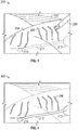
- FIG. 7 an overlay 700 of three NIR images acquired at approximately the same location but at different times (e.g., frames of a video separated by 5, 10, 30 or more seconds) is displayed on a white light image 702.
- a vessel 704 is depicted within tissue 706. Fluorescent dye transits the vessel 704 and perfuses the surrounding tissue.
- a first image of the overlay 700 depicts the flow of the fluorescent dye into the vessel 704 at a first time (solid line).
- the second (short dashed lines) and third (long dashed lines) images of the overlay 700 depict the fluorescent dye as it traverses the vessel 704 and perfuses into the surrounding tissue. Because the time between images is known, an image analysis of the respective images can be undertaken to determine the perfusion vectors 706 in any given direction.
- the difference in location of detected fluorescence within successive images or frames provides a vector of movement of the fluorescent dye within the vessel 704 and tissue 706.
- These vectors can be used to determine a flow path of the fluorescent dye through the vessel 704 and tissue 706. From the vectors the flow path may be determined from any single vector for an image acquired at a specific time.
- the vectors also enable the determination of a centerline of the perfusion of the fluorescent dye. 24.
- the centerline of perfusion may be determined as a median of a plurality of the vectors determined via image processing of the plurality of images.
- FIG. 8 depicts an overlay 800 on a white light image of the centerline of the perfusion 802 of the fluorescent dye, calculated from the vectors of fluorescent dye perfusion.
- the depiction of the centerline of the perfusion 802 requires less processing power, and also provides a generally clearer field of view of the white light image as compared to overlaying an NIR video.
- that centerline data may have a longer lifespan of relevance to the clinician as the location of the vessel may remain a relevant consideration long after the fluorescent dye has saturated the entirety of the tissue 706 or axis requires less computer resources to maintain as compared to the video memory and has longer temporal user value compared to rate threshold information.
- the determined centerlines may be combined from several NIR videos (i.e., multiple images from separate NIR videos) to create a more complete knowledge of the structure of interest.
- an area of interest can be tracked continually during the remainder of the surgery.
- image recognition techniques may be used to follow the anatomy during the dissection and resection process as parts of the anatomy are split into smaller sections or removed entirely. At times, the area of interest may become obscured or covered by other anatomy or instruments. Whether using EM registration and position detection or image-based registration, the system may recover the tracking process when the common landmarks described earlier return into view.
- the clinician may at any time toggle on an anatomy tracking feature to see where the highlighted anatomy has moved to or if it still exists.
- the clinician may have marked an area on the display that is intended to be removed.
- the system of the disclosure can track the area of interest and can notify the surgeon when the tracked area has been entirely removed.
- sentinel lymph nodes are removed, the surgeon can be alerted as to the presence of connected lymph nodes that should be considered for removal as well
Landscapes
- Health & Medical Sciences (AREA)
- Life Sciences & Earth Sciences (AREA)
- Surgery (AREA)
- Engineering & Computer Science (AREA)
- General Health & Medical Sciences (AREA)
- Molecular Biology (AREA)
- Pathology (AREA)
- Veterinary Medicine (AREA)
- Public Health (AREA)
- Biophysics (AREA)
- Biomedical Technology (AREA)
- Heart & Thoracic Surgery (AREA)
- Medical Informatics (AREA)
- Physics & Mathematics (AREA)
- Animal Behavior & Ethology (AREA)
- Nuclear Medicine, Radiotherapy & Molecular Imaging (AREA)
- Radiology & Medical Imaging (AREA)
- Optics & Photonics (AREA)
- Signal Processing (AREA)
- Human Computer Interaction (AREA)
- Immunology (AREA)
- Vascular Medicine (AREA)
- Endoscopes (AREA)
Abstract
Description
- The disclosure relates to surgical imaging systems, and more particularly, to systems and methods for assisting a clinician performing surgery on lymphatic and other luminal structures.
- As technology has advanced, surgeons have largely replaced classical open surgical techniques with minimally invasive techniques such as laparoscopic and thoracoscopic surgery in an effort to minimize trauma to surrounding tissue, reduce pain, reduce scarring, and reduce the length of time a patient is required to stay in the hospital. Minimally invasive surgery, such as the thoracoscopic approach pioneered in the mid-19th century, involves the use of small incisions (from one to several), typically no larger than 3-10mm. Originally performed using a cystoscope, advances in medical technology led to the development of specialized instruments for use in the thoracic cavity, such as a thoracoscope, to view anatomy within the thoracic cavity while performing the surgical procedure. In the late 20th century, Video Assisted Thoracic Surgery (VATS) was developed utilizing a fiber-optic endoscope to further reduce the size of incisions required to make the incision and to provide clearer, more defined images of the thoracic cavity.
- In parallel with the advances in minimally invasive surgeries have come advances in in-situ imaging techniques. Employing these in-situ techniques, dyes, such as indocyanine or methylene blue, can be injected into the body. These dyes are typically injected into blood vessels and other luminal networks so that the blood vessel or other luminal network pathway can be observed when the dyes are excited by various wavelengths of infrared and near-infrared light.
- While these technologies have led to improvements in surgical outcomes, improvements to the technology are always desirable.
- The disclosure is directed to a system and method that enables real-time visual examination of in vivo tissues and selective display of luminal networks lying beneath the surface of the tissues being examined.
- In one aspect, this disclosure features a method of imaging tissue. The method of imaging tissue includes receiving white light images, receiving near infrared (NIR) images, storing the NIR images in memory, and detecting fluorescence in the NIR images. The method of imaging tissue also includes generating composite images including the white light images and NIR images in which the fluorescence is detected. The method of imaging tissue also includes displaying the composite images in a user interface.
- In aspects, implementations of this disclosure may include one or more of the following features. The composite images may be formed of white light images captured at a time after the NIR images are received. The method may also include registering the white light images and the NIR images. The registration may be an electromagnetic-based registration. The registration may be an image-based registration. Detecting fluorescence may include determining which pixels in the NIR images change brightness at a rate faster than a threshold.
- In another aspect, this disclosure features a system for imaging a patient. The system includes an endoscope including a white light source, a near infrared (NIR) light source, and at least one camera capable of capturing reflected white and NIR light. The system also includes a processor in communication with the at least one camera and configured to generate a white light video and an NIR video from the captured reflected white and NIR light. The system also includes a display in communication with the processor to selectively present a user interface including the white light video or the NIR video. The system also includes a memory having stored thereon an application which, when executed by the processor, causes the processor to detect fluorescence in the NIR video, generate a composite video including the white light video and the fluorescence detected in the NIR video, and display the composite video on the display.
- In aspects, implementations of this disclosure may include one or more of the following features. The NIR video may be stored in memory. The application, when executed by the processor, may further cause the processor to register the NIR video to the white light video. The white light video registered to the NIR video may be captured after the detection of the fluorescence in the NIR video. The system may also include an electromagnetic (EM) field generator. The endoscope may include an EM sensor. The application, when executed by the processor, may further cause the processor to determine a position of the EM sensor in a field generated by the EM field generator. The application, when executed by the processor, may further cause the processor to perform image-based registration of the NIR video and the white light video. The displayed composite video may depict the white light video correlated to fluorescing pixels in the NIR video with an altered color. The application, when executed by the processor, may further cause the processor to correlate fluorescing pixels in the NIR video to pixels in the white light video. Detecting fluorescence in the NIR video may include determining which pixels in the NIR video change brightness at a rate faster than a threshold.
- In another aspect, this disclosure features a method of identifying an area of interest in an endoscopic image. The method includes illuminating tissue with white light. The method also includes capturing reflected white light. The method also includes illuminating tissue with near infrared (NIR) light. The method also includes capturing fluorescence emitted by tissue infused with a fluorescent dye. The method also includes displaying the captured reflected white light as a white light video on a display. The method also includes storing the captured fluorescence as a video in a memory. The method also includes displaying the fluorescence video and the white light video on the display.
- In aspects, implementations of this disclosure may include one or more of the following features. The fluorescence video may be registered to the white light video. The registration may be an image-based registration. A composite video including the white light video and fluorescence video may be generated and displayed such that the fluorescence may be observable in the white light video. The method may also include detecting pixels in the fluorescence video corresponding to pixels in the white light video. The method may also include displaying the white light video with the corresponding pixels having a changed color.
- A further aspect of the disclosure is directed to a method of imaging tissue including steps of illuminating tissue with white light, capturing white light images, and illuminating tissue with near infrared (NIR) light. The method further includes detecting fluorescence emitted by tissue infused with a fluorescent dye, converting the detected fluorescence into a centerline of perfusion, and overlaying the centerline of perfusion onto the white light image. The method may include displaying a composite image of the white light image and the centerline of perfusion on a user interface. The centerline of perfusion may be determined from the rate of change of a detected position of detected fluorescence. The centerline of perfusion may be determined as a median of a plurality of vectors determined via image processing of multiple images in which fluorescence is detected. Further, the centerline of perfusion may be determined prior to a current white light video image on which the centerline of perfusion is overlaid. Still further, a current white light image and a prior white light image may be used to register a location of the centerline of perfusion in the current white light image.
- Various aspects and features of the disclosure are described hereinbelow with references to the drawings, wherein:
-
FIG. 1 depicts an endoscope inserted into a patient during a thoracic procedure; -
FIG. 2 depicts a distal portion of an endoscope in accordance with aspects of the disclosure; -
FIG. 3 depicts a white light image captured by the endoscope ofFIG. 1 and displayed in a user interface in accordance with aspects of the disclosure; -
FIG. 4 depicts a near infrared image captured by an endoscope ofFIG. 1 and displayed in a user interface; -
FIG. 5 depicts an imaging system in accordance with aspects of the disclosure; -
FIG. 6 is a flow chart of an endoscopic imaging procedure in accordance with the disclosure; -
FIG. 7 depicts a NIR image captured by the endoscope ofFIG. 1 in accordance with a further aspect of the disclosure; and -
FIG. 8 depicts an overlay of a calculated centerline of a target of interest derived from the NIR image ofFIG. 7 . - The disclosure is directed to a system and method that enables real-time visual examination of in vivo tissues and selective display of luminal networks lying beneath the surface of the tissues being examined.
FIG. 1 depicts anendoscope 100 inserted into the thoracic cavity of a patient (P) and used to image a surface of the patient's lungs (L) as might occur during a thoracic surgery. - Details of the
endoscope 100 can be seen inFIG. 2 , in which adistal surface 102 of theendoscope 100 includes a firstlight source 104, afirst camera 106, a secondlight source 108, and asecond camera 110. Although generally illustrated as being disposed in a circular configuration (i.e., disposed about the circumference of the distal surface 102), it is contemplated that each of the first and secondlight sources second cameras - The
first camera 106 may be a white light optical camera such as a charge-coupled device (CCD) camera, a complementary metal-oxide-semiconductor (CMOS) camera, an N-type metal-oxide-semiconductor (NMOS) camera, or any other suitable white light camera known in the art. Similarly, the firstlight source 104 may be or may include a light emitting diode (LED) emitting white light, although any suitable light emitting device known in the art may be utilized (e.g., the firstlight source 104 may be the end of an optical fiber connected to a light source external to the patient). The secondlight source 108 may be a laser or another emitter of infrared (IR) or near infrared (NIR) light. Finally, thesecond camera 110 may be a CCD camera capable of detecting IR or NIR light. Other cameras capable of capturing IR or NIR light, either with or without filtering, are also contemplated in connection with the disclosure as are multi-spectral cameras such as those capable of capturing white light and NIR light using a single camera. - Following insertion, as shown in
FIG. 1 , the firstlight source 104 and thefirst camera 106 are used for general navigation within the body of the patient. The white light emitted by the firstlight source 104 reflects off one or more tissues of the body and is captured by thefirst camera 106. The images from the first camera are displayed on a display, as shown inFIG. 3. FIG. 3 depicts auser interface 200 depicting the image captured by thefirst camera 106. The majority of the view may be taken up by one or more tissues and may include a number of tissue types, includingconnective tissue 202,organ tissues 204,blood vessels 206, and others. Also shown in theuser interface 200 is aforceps 208, which can be used by the clinician to manipulate the one or more tissues. In the field of view, but not visible under white light visualization using thefirst camera 106, are hidden structures that lie below the tissue surface or are otherwise unobservable, such aslymphatic duct 210 which connectslymph nodes 212, 214 (FIG. 4 ). - To identify structures that are either below the surface of the tissue, or whose structure is not clearly distinguishable from a perspective above the surface of the tissue, various dyes may be employed. One such dye is indocyanine green (ICG) dye. When ICG dye is illuminated with certain frequencies of light in the IR or NIR range, the ICG fluoresces a green color that can be captured by a camera such as the
second camera 108. - The capture of the NIR images can be triggered automatically or as directed by the clinician. The clinician can instruct or control the system to capture the endoscopic image using any suitable method of control available (e.g., footswitch, voice, assistant, or hand motion). Alternatively, the system can perform this task automatically by detecting sudden changes in the image. Automated detection accuracy can be improved through comparison with template images described below. When dyes such as ICG, which generate visible changes, are used the results are seen in the
UI 200. The process of the dye diffusing through the tissue reveals anatomic detail, such as vasculature and parts of the lymphatic system. The pattern of diffusion provides information on the direction of flow within that structure. By capturing a video of the diffusion in the lymphatic or another luminal system, it is possible to show the clinician the network of connections (e.g., lymph nodes and lymphatic ducts) and to determine which connections are the sentinel nodes, thus allowing for more complete harvesting of such structures during cancer surgery. - With reference back to
FIG. 2 , to detect the location ofblood vessels 206 that might be hidden or not abundantly apparent under white light visualization, ICG dye can be injected into the blood stream of the patient at a location proximate to an area of interest. As the blood having the ICG dye is transported through the blood vessels, the blood vessels will, for a time, appear distinct from the surrounding tissue when illuminated with an NIR light source. Thus, by illuminating theorgan tissues 204 inFIG. 3 with NIR light from the secondlight source 108 and capturing the returned fluorescence from the ICG in the blood stream,blood vessels 206 will appear in theuser interface 300, as shown inFIG. 4 . Similarly, if alymph node 212 is injected, diffusion through thelymphatic duct 210 to thelymph node 214 can be observed. - As shown in
FIG. 4 , the remainder of the tissue, which has not been infused with ICG dye, is much less visible or not visible at all. Instead, theUI 300 displays just those tissues through which the dye is diffusing. InFIG. 4 , theblood vessels 206, thelymph nodes lymphatic duct 210 are clearly displayed. In one aspect, a clinician employing ICG and two imaging systems as described inFIG. 2 , can toggle betweenUI 200 andUI 300 alternately so that the clinician can attempt to visualize the structures of theblood vessels 206 while performing most of their operation under white light visualization. Typically, the clinician will alternate between the two camera displays (FIGS. 3 and 4 ) to ensure that they are not about to damage certain tissues such as blood vessels, lymphatic ducts, or lymph nodes, or to make some other clinical determination during a procedure (e.g., that all desiredlymph nodes lymphatic duct 210 are removed). In addition, theUI 200 may display a composite ofUI 200 andUI 300 as will be explained in greater detail below. - While the systems and methods described above are useful, dyes such as ICG have certain issues that impact the way they are used. First, some dyes tend to perfuse through the entirety of the tissues 202-206 as the dyes are passed through the circulatory system. Substantially all tissues receive blood from the circulatory system. As a result, after a period, the entirety of the tissue proximate to the tissue into which a dye has been injected will be perfused, thus saturating the captured images with fluorescence and rendering the fluorescence captured by the
second camera 110 useless. Secondly, dyes dissipate relatively quickly and are only visible for a couple of minutes after injection. Many of these dissipating dyes also have a level of toxicity that makes it difficult or less than desirable to perform multiple injections of the dyes. These limitations force the clinician to act immediately or at least very quickly on the information gleaned from the use of the dyes and imaging the tissues. -
FIG. 5 depicts a system employing a method of the disclosure. InFIG. 5 , anendoscope 100 is connected to adisplay 220 to displayuser interfaces workstation 400. Theworkstation 400 may be a desktop computer or a tower configuration withdisplay 220 or may be a laptop computer or other computing device. Theworkstation 400 includes aprocessor 402 which executes software stored in thememory 404. Thememory 404 may store video and other imaging data captured by theendoscope 100 or pre-procedure images from, for example, a CT scan. In addition, thememory 404 may store one ormore applications 406 to be executed on theprocessor 402. Though not shown here, thedisplay 220 may be incorporated into a head mounted display such as an augmented reality (AR) headset such as the HoloLens offered by Microsoft Corp. - A network interface 408 allows the
workstation 400 to communicate with a variety of other devices and systems via the Internet. The network interface 408 may connect theworkstation 400 via a wired or wireless connection. Additionally or alternatively the communication may be via an ad-hoc Bluetooth or wireless networks enabling communication with a wide-area network (WAN) and or a local area network (LAN). The network interface 408 may connect to the internet via one or more gateways, routers, and network address translation (NAT) devices. The network interface 408 may communicate with acloud storage system 410, in which further image data and videos may be stored. Thecloud storage system 410 may be remote from or on the premises of the hospital such as in a control or hospital information technology room. Aninput module 412 receives inputs from an input device such as keyboard, mouse, voice commands, etc. Anoutput device 414 connects theprocessor 402 andmemory 404 to a variety of output devices such as thedisplay 220. Finally, theworkstation 400 may include itsown display 416, which may be a touchscreen display. - In at least one aspect, the
endoscope 100 includes a location sensor such as an electromagnetic (EM)sensor 112 which receives electromagnetic signals from afield generator 114 generating three or more electromagnetic fields. One of theapplications 406 stored in thememory 404 and executed by theprocessor 402 may determine the position of theEM sensor 112 in the EM field generated by thefield generator 114. Determination of the position of the endoscope and the first andsecond cameras - In accordance with the disclosure, a method of utilizing a video of the dye diffusion is described herein. Rather than simply imaging the tissue so that it can be displayed while the clinician is performing the surgery, the injection of the ICG dye and its diffusion through the tissue is captured as a video. The captured video of the diffusion of the ICG dye through the tissue can be played back at any time by the clinician. This allows the clinician to observe the direction of the diffusion as well as the relative speeds of diffusion through different vessels. This video of the diffusion of the ICG dye can be played back at a suitable speed (e.g., either at normal speeds or at high speeds) so that the clinician can observe the locations of the blood vessels or other tissues such as the
lymph nodes FIG. 3 ) that are captured by thefirst camera 106 and displayed on thedisplay 220. - In one aspect, the white light images are captured by the
first camera 106. Thelymph node 212 or a sentinel node upstream from thelymph node 212 may be injected with the ICG dye. The secondlight source 108 and thesecond camera 110 may be selected and, by observing fluorescence of the ICG dye when under NIR illumination, the location of thelymph nodes lymph node 212 to thelymph node 214, can be observed. The direction of travel through the lymphatic system can be an important factor in determining the likely spread of cancer and other diseases. Thus, by observing the direction of travel, if thelymph node 214 is down stream from thelymph node 212, then a clinical determination may be made as to whetherlymph node 214 should be removed. This determination is usually based on the proximity of thelymph node 214 to a cancerous lymph node or a sentinel node. In addition, a more complete map of the lymph node tree can be developed and stored in thememory 404. - Because a video of the lymphatic system or at least a portion of the lymphatic system is stored in the
memory 404, the clinician can reference the video at any time. In accordance with one aspect of the disclosure, one or more registration points are identified either automatically or by the user in the white light video, which may be captured simultaneously with the NIR video. Since the NIR video and the white light video may be captured simultaneously (or at alternating times which occur at a high speed), by identifying a location of a structure in one video, that same structure can be located in the other video. This allows the data from one, e.g., the position of thelymph nodes lymphatic duct 210 connecting them, to be accurately displayed as an overlay on the white light video. - Further, by identifying registration points, image recognition techniques can be employed to allow the system to display the
lymph nodes endoscope 100 where one of thelymph nodes white light camera 106. In such a scenario, a representation of the lymph node behind the intervening tissue may still be displayed. This may be very useful when, for example, navigating theendoscope 100 within the patient. Once the registration points are in the view of theendoscope 100, the location of thelymph nodes display 220. - Alternatively, image recognition techniques make it possible to determine which pixels in the image of the NIR camera are detecting fluorescence. Because the field of view of the white light
first camera 106 and theNIR camera 110 are known, the location of thelymph nodes lymphatic duct 210 connecting them can be observed. The pixel data can then be transferred to, overlaid on, or otherwise applied to the white light images, so that the corresponding pixels of the white light images in the substantially same field of view are highlighted to display the locations of thelymph nodes first camera 106 and thesecond camera 110 are described in greater detail below. -
FIG. 6 shows aflow chart 500 of a method for use by the system displayed inFIG. 5 . Following insertion of an endoscope into, for example, the thoracic cavity as shown inFIG. 1 the system may optionally detect the position of the endoscope atstep 502, The position of theendoscope 100 may be detected using theEM sensor 112 and theEM field generator 114. Those of skill in the art will recognize that EM detection is not necessarily required for use with the instant imaging techniques and other techniques such as image matching to pre-procedural images (e.g., CT images) or three-dimensional models derived from such images, as well as two dimensional images generated from the 3D images may be employed to determine the position of the endoscope relative to the tissue being examined. Once inserted, theendoscope 100 may be navigated within the patient. While navigating, the tissue is illuminated with white light atstep 504 and the white light reflects off the tissue and other structures and white light images are captured atstep 506 and can be stored inmemory 404 atstep 508 and may be simultaneously displayed ondisplay 220. Anapplication 406 stored inmemory 404 may store the images in a fashion such that they can be replayed sequentially in a white light video. The white light images permit the clinician to observe the tissue and visually inspect and identify locations for further analysis. Once positioned at a location where detection of areas of interest (e.g., lymph nodes, blood vessels, etc.) is desired, dye may be injected into the tissue at a clinically appropriate position such that the dye will diffuse through the area of interest. Once injected, the area of interest is illuminated with NIR light atstep 510. As noted above, the dye, when excited by NIR light, fluoresces. The fluorescence can then be detected atstep 512 via thesecond camera 110. The detected fluorescence is converted into NIR images atstep 514 and saved inmemory 404 atstep 516. These images can be saved at a frequency allowing for the observation of the dye as it diffuses through an area of interest. The frequency may be, for example 15, 30, 45, 60, 120 images per second, as well integer values therebetween. The NIR images may be compiled into a video so that the diffusion may be observed over time. The diffusion video may also be saved inmemory 404 atstep 517. - The acquiring of both NIR and white light images may occur in an alternating fashion or simultaneously. The user may determine which of the images to display on the
display 220. This may be the live white light images, the live NIR images, or the NIR diffusion video stored in thememory 404. If it is a diffusion video stored inmemory 404 that is desired to be displayed, the appropriate diffusion video may be selected by a clinician and the diffusion video may be loaded into anapplication 406 atstep 518 for display. In addition, atstep 520, a speed of the video may be adjusted in response to a request received from a user. Increasing the speed of the video can be useful to the clinician in clearly and quickly outlining where areas of interest (e.g., blood vessels, lymph nodes, lymphatic ducts, etc.) are located. This can allow a clinician to play the video forwards and backwards, and at varying rates of speed to ensure that the locations of the areas of interest are well understood. Knowledge of these areas can assist the clinician when determining which structures to cut, avoid, biopsy, or remove as necessary. - The video, as adjusted at
step 518 may be displayed on thedisplay 220. The presentation of the video may be as a picture-in-picture format allowing the clinician to observe both the video and the real-time white light images received from the endoscope. Alternatively, the video and the real-time white light images may be displayed side-by-side and/or having approximately the same size. - In a further aspect, where the field of view of the white light images captured by the endoscope at least partially aligns with the field of view of the video stored in memory, a registration of the video and the live images may be undertaken at
step 522. Following registration, the diffusion video (or an individual NIR image) may be displayed as an overlay on the real-time white light video (or an individual image in the white light video) atstep 524. This overlay of the NIR video, in which only those portions of the field of view (FOV) which fluoresce can be readily observed, results in a composite video of the NIR video and the white light video viewable on thedisplay 220. In this way, the NIR video can be used to identify structures in the FOV of the white light video. As the FOV of the endoscope changes with its movement, those portions of the white light video which are no longer aligned with the FOV of the NIR video may no longer be depicted as a composite video, but rather only the white light video is displayed. This may be considered an indicator to the clinician to move the endoscope back to a location where the NIR video clearly reveals the locations of the areas of interest. - Additionally, or alternatively if any portion of the structures of the NIR video are still in the FOV of the white light, the white light video may be warped in order to fit the portion of the NIR video in the FOV of the white light video. In embodiments with
EM sensor 112 collecting position data of thecameras - If a 3D endoscope is used, the coordinates of the area of interest may be extracted directly from the scanned model annotated with any additional information extracted from the images such as luminal network connection data and fluid flow direction as described for lymph nodes above. This additional data may be stored in the
memory 404 and available for use by the clinician as the endoscope is returned to one or more stored coordinate positions. - In accordance with another aspect of the disclosure, an
application 406 stored inmemory 404 can be employed to analyze the NIR images captured by theendoscope 100 atsecond camera 110. This may occur in real time as the images are captured or may involve processing the video stored inmemory 404. The images are analyzed atstep 526 to determine which pixels in the NIR images of the diffusion video are experiencing a change in brightness or illuminance (typically measured in lux or foot-candle). The change in brightness is a result of the NIR light from the secondlight source 108 illuminating the ICG dye that is diffusing through the area of interest. - Because the NIR images may be captured substantially simultaneously with the white light images, the images are necessarily registered with one another. Because of the registration of the simultaneous capture of the images, by determining which pixels in the NIR images are changing from not fluorescing to fluorescing, an indication of the location of areas of interest can be made. The rate of the change is relevant to the identification of the larger vessels carrying the dye. Blood vessels and other luminal structures greater than a certain diameter allow the dye to pass through relatively quickly and thus change from not fluorescing to fluorescing quickly. By detecting this rate of change, and only identifying those pixels that change at a rate greater than a threshold, those pixels that are slower to change can be eliminated from further processing and thus prevent the saturation described above.
- Once the pixels that are changing at a rate greater than a predetermined rate are identified, these pixels can then be correlated to the same pixels in the FOV of the white light images at
step 528. Once the pixels are identified in the white light images, these pixels can then have their brightness or color changed such that the area of interest is revealed in the white light images atstep 530 and this altered white light image can be displayed atstep 532. - As noted herein above, registration of the NIR images and the white light images is a useful feature in enabling the data derived from the NIR images to be observed in the white light images. One form of registration requires the use of the
EM sensor 112 and thefield generator 114. A detected position of theEM sensor 112 in the EM field can be correlated to each frame of both the white light videos and the NIR videos. With reference to the position data of the NIR images, once the position data for each frame in the NIR video depicting the perfusion of the dye through the area of interest is determined, the NIR video data can be made available and displayed in the white light images as described above using the correlation of the position of the NIR images with the white light images. - In addition to EM field position detection and registration, other forms of registration are also possible. For example, an
application 406 stored inmemory 404 may engage in image detection that identifies structures or other hard points in every image of the white light video atstep 534. These hard points are also necessarily in the NIR images that are simultaneously captured, and as described above. As a result, the white light video images and the NIR video images are necessarily registered with one another. However, if use is to be made of the diffusion video at a later time (e.g., later in a long procedure, or even in a subsequent procedure), some form of registration is required. By identifying registration points in the white light video that was captured substantially simultaneously with the NIR video images, when these registration points are observed in subsequent white light video images, a correlation or registration can be performed between these later captured video images and the original white light video images. - The registration may include a
step 536 of determining a FOV of theendoscope 100 and white light images captured by the endoscope. Registration of the real time white light images with the previously captured white light images necessarily also registers the previously captured NIR images to the current white light images atstep 538, and thus the diffusion video with the real time white light images. In this way, either selectively or automatically, as new white light images are captured via theendoscope 100, the fluorescence observed in the NIR images of the diffusion video from the same FOV as the real-time white light video can be displayed on thedisplay 220 atstep 540. - Yet a further aspect of the disclosure is described with reference to
FIGS. 7 and 8 . In instances where displaying a previously acquired NIR video is challenging, or results in images that are less than entirely useful for a given case, an alternative may be employed. - In
FIG. 7 anoverlay 700 of three NIR images acquired at approximately the same location but at different times (e.g., frames of a video separated by 5, 10, 30 or more seconds) is displayed on awhite light image 702. InFIG. 7 avessel 704 is depicted withintissue 706. Fluorescent dye transits thevessel 704 and perfuses the surrounding tissue. A first image of theoverlay 700 depicts the flow of the fluorescent dye into thevessel 704 at a first time (solid line). The second (short dashed lines) and third (long dashed lines) images of theoverlay 700 depict the fluorescent dye as it traverses thevessel 704 and perfuses into the surrounding tissue. Because the time between images is known, an image analysis of the respective images can be undertaken to determine theperfusion vectors 706 in any given direction. The difference in location of detected fluorescence within successive images or frames provides a vector of movement of the fluorescent dye within thevessel 704 andtissue 706. These vectors can be used to determine a flow path of the fluorescent dye through thevessel 704 andtissue 706. From the vectors the flow path may be determined from any single vector for an image acquired at a specific time. The vectors also enable the determination of a centerline of the perfusion of the fluorescent dye. 24. The centerline of perfusion may be determined as a median of a plurality of the vectors determined via image processing of the plurality of images. -
FIG. 8 depicts anoverlay 800 on a white light image of the centerline of theperfusion 802 of the fluorescent dye, calculated from the vectors of fluorescent dye perfusion. In some instances, the depiction of the centerline of theperfusion 802 requires less processing power, and also provides a generally clearer field of view of the white light image as compared to overlaying an NIR video. Still further, that centerline data may have a longer lifespan of relevance to the clinician as the location of the vessel may remain a relevant consideration long after the fluorescent dye has saturated the entirety of thetissue 706 or axis requires less computer resources to maintain as compared to the video memory and has longer temporal user value compared to rate threshold information. Further the determined centerlines may be combined from several NIR videos (i.e., multiple images from separate NIR videos) to create a more complete knowledge of the structure of interest. - As a result of the processes above, an area of interest can be tracked continually during the remainder of the surgery. For example, image recognition techniques may be used to follow the anatomy during the dissection and resection process as parts of the anatomy are split into smaller sections or removed entirely. At times, the area of interest may become obscured or covered by other anatomy or instruments. Whether using EM registration and position detection or image-based registration, the system may recover the tracking process when the common landmarks described earlier return into view.
- In one aspect the clinician may at any time toggle on an anatomy tracking feature to see where the highlighted anatomy has moved to or if it still exists. In the case of lymph node resection, the clinician may have marked an area on the display that is intended to be removed. The system of the disclosure can track the area of interest and can notify the surgeon when the tracked area has been entirely removed. When sentinel lymph nodes are removed, the surgeon can be alerted as to the presence of connected lymph nodes that should be considered for removal as well
- While several aspects of the disclosure have been shown in the drawings, it is not intended that the disclosure be limited thereto, as it is intended that the disclosure be as broad in scope as the art will allow and that the specification be read likewise. Therefore, the above description should not be construed as limiting, but merely as exemplifications of particular aspects.
- The invention may be described by reference to the following numbered paragraphs:-
- 1. A method of imaging tissue comprising:
- capturing white light images;
- illuminating with near infrared (NIR) light;
- detecting fluorescence;
- converting detected fluorescence to NIR images;
- generating composite images including the white light images and NIR images in which the fluorescence is detected; and
- displaying the composite images in a user interface.
- 2. The method of paragraph 1, wherein the composite images are formed of white light images captured at a time after the NIR images are received.
- 3. The method of paragraph 2, further comprising registering the white light images and the NIR images.
- 4. The method of paragraph 3, wherein the registration is an electromagnetic-based registration.
- 5. The method of paragraph 3, wherein the registration is an image-based registration.
- 6. The method of paragraph 1, wherein detecting fluorescence includes determining which pixels in the NIR images change brightness at a rate faster than a threshold.
- 7. A system for imaging a patient, comprising:
- an endoscope including a white light source, a near infrared (NIR) light source, and at least one camera capable of capturing while light images and detecting fluorescence;
- a processor in communication with the at least one camera and configured to generate a white light video from the captured white light images and a diffusion video of the detected fluorescence;
- a display in communication with the processor to selectively present a user interface including the white light video or the diffusion video; and
- a memory having stored thereon an application which, when executed by the processor, causes the processor to:
- convert detected fluorescence into NIR images;
- compile the NIR images into a diffusion video;
- generate a composite video including the white light video and the diffusion video; and
- display the composite video on the display.
- 8. The system of paragraph 7, wherein the diffusion video is stored in memory.
- 9. The system of paragraph 7, wherein the application, when executed by the processor, further causes the processor to register the diffusion video to the white light video.
- 10. The system of paragraph 9, wherein the white light video registered to the diffusion video is captured after the detection of the fluorescence in the NIR video.
- 11. The system of paragraph 9, further comprising an electromagnetic (EM) field generator,
- wherein the endoscope includes an EM sensor, and
- wherein the application, when executed by the processor, further causes the processor to determine a position of the EM sensor in a field generated by the EM field generator.
- 12. The system of paragraph 9, wherein the application, when executed by the processor, further causes the processor to perform image-based registration of the diffusion video and the white light video.
- 13. The system of paragraph 12, wherein the displayed composite video depicts the white light video correlated to fluorescing pixels in the diffusion video with an altered color.
- 14. The system of paragraph 7, wherein the application, when executed by the processor, further causes the processor to correlate fluorescing pixels in the diffusion video to pixels in the white light video.
- 15. The system of paragraph 7, wherein detecting fluorescence in the diffusion video includes determining which pixels in the diffusion video change brightness at a rate faster than a threshold.
- 16. A method of identifying an area of interest in an endoscopic image comprising:
- illuminating tissue with white light;
- capturing white light images;
- illuminating tissue with near infrared (NIR) light;
- detecting fluorescence emitted by tissue infused with a fluorescent dye;
- displaying the captured white light images on a display;
- converting the detected fluorescence to NIR images and storing them in memory;
- compiling the NIR images as a diffusion video; and
- displaying the diffusion video and the white light images on the display.
- 17. The method of paragraph 16, wherein the diffusion video is registered to the white light images.
- 18. The method of paragraph 17, wherein the registration is an image-based registration.
- 19. The method of paragraph 17, wherein a composite video including the white light images and diffusion video is generated and displayed such that the fluorescence is observable in the white light images.
- 20. The method of paragraph 16, further comprising:
- detecting pixels in the diffusion video corresponding to pixels in the white light images; and
- displaying the white light images with the corresponding pixels having a changed color.
Claims (15)
- A method of imaging tissue comprising:capturing white light images;illuminating with near infrared (NIR) light;detecting fluorescence;converting detected fluorescence to NIR images;generating composite images including the white light images and NIR images in which the fluorescence is detected; anddisplaying the composite images in a user interface.
- The method of claim 1, wherein the composite images are formed of white light images captured at a time after the NIR images are received.
- The method of claim 2, further comprising registering the white light images and the NIR images.
- The method of claim 3, wherein the registration is an electromagnetic-based registration; and/or wherein the registration is an image-based registration.
- The method of any preceding claim, wherein detecting fluorescence includes determining which pixels in the NIR images change brightness at a rate faster than a threshold.
- A system for imaging a patient, comprising:an endoscope including a white light source, a near infrared (NIR) light source, and at least one camera capable of capturing while light images and detecting fluorescence;a processor in communication with the at least one camera and configured to generate a white light video from the captured white light images and a diffusion video of the detected fluorescence;a display in communication with the processor to selectively present a user interface including the white light video or the diffusion video; anda memory having stored thereon an application which, when executed by the processor, causes the processor to:convert detected fluorescence into NIR images;compile the NIR images into a diffusion video;generate a composite video including the white light video and the diffusion video; anddisplay the composite video on the display.
- The system of claim 6, wherein the diffusion video is stored in memory; and/or wherein the application, when executed by the processor, further causes the processor to register the diffusion video to the white light video; preferably wherein the white light video registered to the diffusion video is captured after the detection of the fluorescence in the NIR video.
- The system of claim 6 or claim 7, further comprising an electromagnetic (EM) field generator,wherein the endoscope includes an EM sensor, andwherein the application, when executed by the processor, further causes the processor to determine a position of the EM sensor in a field generated by the EM field generator.
- The system of any of claims 6 to 8, wherein the application, when executed by the processor, further causes the processor to perform image-based registration of the diffusion video and the white light video; preferably wherein the displayed composite video depicts the white light video correlated to fluorescing pixels in the diffusion video with an altered color.
- The system of any of claims 6 to 9, wherein the application, when executed by the processor, further causes the processor to correlate fluorescing pixels in the diffusion video to pixels in the white light video.
- The system of claim 0, wherein detecting fluorescence in the diffusion video includes determining which pixels in the diffusion video change brightness at a rate faster than a threshold.
- A method of identifying an area of interest in an endoscopic image comprising:illuminating tissue with white light;capturing white light images;illuminating tissue with near infrared (NIR) light;detecting fluorescence emitted by tissue infused with a fluorescent dye;displaying the captured white light images on a display;converting the detected fluorescence to NIR images and storing them in memory;compiling the NIR images as a diffusion video; anddisplaying the diffusion video and the white light images on the display.
- The method of claim 12, wherein the diffusion video is registered to the white light images.
- The method of claim 13, wherein the registration is an image-based registration; preferably wherein a composite video including the white light images and diffusion video is generated and displayed such that the fluorescence is observable in the white light images.
- The method of claim 14, further comprising:detecting pixels in the diffusion video corresponding to pixels in the white light images; anddisplaying the white light images with the corresponding pixels having a changed color.
Applications Claiming Priority (2)
| Application Number | Priority Date | Filing Date | Title |
|---|---|---|---|
| US201962946307P | 2019-12-10 | 2019-12-10 | |
| US17/072,753 US12102298B2 (en) | 2019-12-10 | 2020-10-16 | Lymphatic system tracking |
Publications (1)
| Publication Number | Publication Date |
|---|---|
| EP3878345A1 true EP3878345A1 (en) | 2021-09-15 |
Family
ID=76208896
Family Applications (1)
| Application Number | Title | Priority Date | Filing Date |
|---|---|---|---|
| EP20212737.9A Pending EP3878345A1 (en) | 2019-12-10 | 2020-12-09 | Lymphatic system tracking |
Country Status (2)
| Country | Link |
|---|---|
| US (1) | US12102298B2 (en) |
| EP (1) | EP3878345A1 (en) |
Cited By (1)
| Publication number | Priority date | Publication date | Assignee | Title |
|---|---|---|---|---|
| DE102022126824A1 (en) * | 2022-10-13 | 2024-04-18 | Karl Storz Se & Co. Kg | Method for superimposing overlay recording information with a live image and a corresponding device |
Families Citing this family (3)
| Publication number | Priority date | Publication date | Assignee | Title |
|---|---|---|---|---|
| US12127890B1 (en) * | 2021-08-11 | 2024-10-29 | Navakanth Gorrepati | Mixed reality endoscopic retrograde cholangiopancreatopgraphy (ERCP) procedure |
| US20230068745A1 (en) * | 2021-09-02 | 2023-03-02 | Covidien Lp | Real-time registration using near infrared fluorescence imaging |
| WO2023097606A1 (en) * | 2021-12-02 | 2023-06-08 | Covidien Lp | Near-infrared fluorescence imaging system with image quality tuning |
Citations (6)
| Publication number | Priority date | Publication date | Assignee | Title |
|---|---|---|---|---|
| US20100286529A1 (en) * | 2009-05-08 | 2010-11-11 | Novadaq Technologies Inc. | Near infra red fluorescence imaging for visualization of blood vessels during endoscopic harvest |
| US20110082369A1 (en) * | 2009-10-07 | 2011-04-07 | Intuitive Surgical, Inc. | Methods and apparatus for displaying enhanced imaging data on a clinical image |
| US20140024948A1 (en) * | 2011-03-31 | 2014-01-23 | Olympus Corporation | Fluoroscopy apparatus |
| US20150018690A1 (en) * | 2013-07-12 | 2015-01-15 | Korea Electrotechnology Research Institute | Apparatus and method for detecting nir fluorescence at sentinel lymph node |
| US20160262602A1 (en) * | 2015-03-09 | 2016-09-15 | Steven Sounyoung Yu | Laparoscopic Cholecystectomy With Fluorescence Cholangiography |
| KR20190032758A (en) * | 2017-09-20 | 2019-03-28 | 인더스마트 주식회사 | Apparatus and method for detecting near-infrared fluorescence |
Family Cites Families (138)
| Publication number | Priority date | Publication date | Assignee | Title |
|---|---|---|---|---|
| US5057494A (en) | 1988-08-03 | 1991-10-15 | Ethicon, Inc. | Method for preventing tissue damage after an ischemic episode |
| US5321113A (en) | 1993-05-14 | 1994-06-14 | Ethicon, Inc. | Copolymers of an aromatic anhydride and aliphatic ester |
| US6003517A (en) | 1998-04-30 | 1999-12-21 | Ethicon Endo-Surgery, Inc. | Method for using an electrosurgical device on lung tissue |
| US6413981B1 (en) | 1999-08-12 | 2002-07-02 | Ortho-Mcneil Pharamceutical, Inc. | Bicyclic heterocyclic substituted phenyl oxazolidinone antibacterials, and related compositions and methods |
| US6608081B2 (en) | 1999-08-12 | 2003-08-19 | Ortho-Mcneil Pharmaceutical, Inc. | Bicyclic heterocyclic substituted phenyl oxazolidinone antibacterials, and related compositions and methods |
| US6750034B1 (en) | 2000-06-30 | 2004-06-15 | Ortho-Mcneil Pharmaceutical, Inc. | DNA encoding human serine protease D-G |
| CA2421638A1 (en) | 2000-09-11 | 2002-03-21 | Closure Medical Corporation | Bronchial occlusion method and apparatus |
| US6472372B1 (en) | 2000-12-06 | 2002-10-29 | Ortho-Mcneil Pharmaceuticals, Inc. | 6-O-Carbamoyl ketolide antibacterials |
| EP1407004B1 (en) | 2001-05-15 | 2009-08-05 | Ortho-McNeil-Janssen Pharmaceuticals, Inc. | Ex-vivo priming for generating cd40-ligand specific cytotoxic t lymphocytes to treat autoimmune and allergic disease |
| US20030013972A1 (en) | 2001-05-29 | 2003-01-16 | Makin Inder Raj. S. | Treatment of lung lesions using ultrasound |
| US7607440B2 (en) | 2001-06-07 | 2009-10-27 | Intuitive Surgical, Inc. | Methods and apparatus for surgical planning |
| MXPA03006874A (en) | 2002-07-31 | 2004-09-03 | Johnson & Johnson | Long term oxygen therapy system. |
| US20040120981A1 (en) | 2002-12-20 | 2004-06-24 | Aruna Nathan | Crosslinked alkyd polyesters for medical applications |
| JP2007525946A (en) | 2003-04-30 | 2007-09-13 | セントカー・インコーポレーテツド | CNGH0010-specific polynucleotides, polypeptides, antibodies, compositions, methods and uses |
| KR20060029276A (en) | 2003-07-04 | 2006-04-05 | 존슨 앤드 존슨 리서치 피티와이 리미티드 | Method for detecting alkylated cytosine in DNA |
| CA2587909C (en) | 2004-11-16 | 2016-01-05 | Robert L. Barry | Device and method for lung treatment |
| WO2006060653A2 (en) | 2004-11-30 | 2006-06-08 | Veridex Llc | Lung cancer prognostics |
| US9055906B2 (en) | 2006-06-14 | 2015-06-16 | Intuitive Surgical Operations, Inc. | In-vivo visualization systems |
| US11389235B2 (en) | 2006-07-14 | 2022-07-19 | Neuwave Medical, Inc. | Energy delivery systems and uses thereof |
| US7655004B2 (en) | 2007-02-15 | 2010-02-02 | Ethicon Endo-Surgery, Inc. | Electroporation ablation apparatus, system, and method |
| US8335359B2 (en) | 2007-07-20 | 2012-12-18 | General Electric Company | Systems, apparatus and processes for automated medical image segmentation |
| SE532644C2 (en) | 2008-07-03 | 2010-03-09 | Aamic Ab | Procedure for analyzing circulating antibodies |
| US8361066B2 (en) | 2009-01-12 | 2013-01-29 | Ethicon Endo-Surgery, Inc. | Electrical ablation devices |
| US20180009767A9 (en) | 2009-03-19 | 2018-01-11 | The Johns Hopkins University | Psma targeted fluorescent agents for image guided surgery |
| US10004387B2 (en) | 2009-03-26 | 2018-06-26 | Intuitive Surgical Operations, Inc. | Method and system for assisting an operator in endoscopic navigation |
| JP6153865B2 (en) | 2010-05-03 | 2017-06-28 | ニューウェーブ メディカル, インコーポレイテッドNeuwave Medical, Inc. | Energy delivery system |
| US8827934B2 (en) | 2011-05-13 | 2014-09-09 | Intuitive Surgical Operations, Inc. | Method and system for determining information of extrema during expansion and contraction cycles of an object |
| US8900131B2 (en) | 2011-05-13 | 2014-12-02 | Intuitive Surgical Operations, Inc. | Medical system providing dynamic registration of a model of an anatomical structure for image-guided surgery |
| US20130303944A1 (en) | 2012-05-14 | 2013-11-14 | Intuitive Surgical Operations, Inc. | Off-axis electromagnetic sensor |
| EP2809249B1 (en) | 2012-02-03 | 2018-12-26 | Intuitive Surgical Operations, Inc. | Steerable flexible needle with embedded shape sensing |
| EP2849668B1 (en) | 2012-05-14 | 2018-11-14 | Intuitive Surgical Operations Inc. | Systems and methods for registration of a medical device using rapid pose search |
| KR102171520B1 (en) | 2012-05-14 | 2020-10-29 | 인튜어티브 서지컬 오퍼레이션즈 인코포레이티드 | Systems and methods for deformation compensation using shape sensing |
| US10039473B2 (en) | 2012-05-14 | 2018-08-07 | Intuitive Surgical Operations, Inc. | Systems and methods for navigation based on ordered sensor records |
| EP3524184B1 (en) | 2012-05-14 | 2021-02-24 | Intuitive Surgical Operations Inc. | Systems for registration of a medical device using a reduced search space |
| US20130303945A1 (en) | 2012-05-14 | 2013-11-14 | Intuitive Surgical Operations, Inc. | Electromagnetic tip sensor |
| US9429696B2 (en) | 2012-06-25 | 2016-08-30 | Intuitive Surgical Operations, Inc. | Systems and methods for reducing measurement error in optical fiber shape sensors |
| US9801551B2 (en) | 2012-07-20 | 2017-10-31 | Intuitive Sugical Operations, Inc. | Annular vision system |
| JP6074587B2 (en) | 2012-08-06 | 2017-02-08 | 株式会社Joled | Display panel, display device and electronic device |
| CN106562757B (en) | 2012-08-14 | 2019-05-14 | 直观外科手术操作公司 | The system and method for registration for multiple vision systems |
| EP2906133B1 (en) | 2012-10-12 | 2022-03-23 | Intuitive Surgical Operations, Inc. | Determining position of medical device in branched anatomical structure |
| US20140188440A1 (en) | 2012-12-31 | 2014-07-03 | Intuitive Surgical Operations, Inc. | Systems And Methods For Interventional Procedure Planning |
| JP6363165B2 (en) | 2013-03-15 | 2018-07-25 | インテュイティブ サージカル オペレーションズ, インコーポレイテッド | Shape sensor system for tracking interventional instruments and method of using the system |
| CN114343608B (en) | 2013-07-29 | 2024-07-26 | 直观外科手术操作公司 | Shape sensor system with redundant sensing |
| KR102356881B1 (en) | 2013-08-15 | 2022-02-03 | 인튜어티브 서지컬 오퍼레이션즈 인코포레이티드 | Graphical user interface for catheter positioning and insertion |
| CN105473098B (en) | 2013-08-15 | 2019-03-26 | 直观外科手术操作公司 | System and method for medical procedure validation |
| CN105939647B (en) | 2013-10-24 | 2020-01-21 | 奥瑞斯健康公司 | Robot-assisted endovascular surgery system and related methods |
| KR102337440B1 (en) | 2013-12-09 | 2021-12-10 | 인튜어티브 서지컬 오퍼레이션즈 인코포레이티드 | Systems and methods for device-aware flexible tool registration |
| AU2015204201B2 (en) | 2014-01-06 | 2019-11-28 | Body Vision Medical Ltd. | Surgical devices and methods of use thereof |
| CN106170265B (en) | 2014-02-04 | 2020-06-30 | 直观外科手术操作公司 | System and method for non-rigid deformation of tissue for virtual navigation of interventional tools |
| US20150223765A1 (en) | 2014-02-07 | 2015-08-13 | Intuitive Surgical Operations, Inc. | Systems and methods for using x-ray field emission to determine instrument position and orientation |
| KR102521043B1 (en) | 2014-03-17 | 2023-04-14 | 인튜어티브 서지컬 오퍼레이션즈 인코포레이티드 | Surgical system including a non-white light general illuminator |
| US10912523B2 (en) | 2014-03-24 | 2021-02-09 | Intuitive Surgical Operations, Inc. | Systems and methods for anatomic motion compensation |
| CN106535812B (en) | 2014-03-28 | 2020-01-21 | 直观外科手术操作公司 | Surgical system with haptic feedback based on quantitative 3D imaging |
| AU2015290043B2 (en) | 2014-07-18 | 2019-08-22 | Ethicon, Inc. | Methods and devices for controlling the size of emphysematous bullae |
| ES2797748T3 (en) | 2014-07-18 | 2020-12-03 | Ethicon Inc | Mechanical retraction by anchoring to reduce lung volume |
| EP3174490B1 (en) | 2014-07-28 | 2020-04-15 | Intuitive Surgical Operations, Inc. | Systems and methods for planning multiple interventional procedures |
| KR20220065894A (en) | 2014-07-28 | 2022-05-20 | 인튜어티브 서지컬 오퍼레이션즈 인코포레이티드 | Systems and methods for intraoperative segmentation |
| KR102542848B1 (en) | 2014-08-23 | 2023-06-14 | 인튜어티브 서지컬 오퍼레이션즈 인코포레이티드 | Systems and methods for display of pathological data in an image guided procedure |
| US10373719B2 (en) | 2014-09-10 | 2019-08-06 | Intuitive Surgical Operations, Inc. | Systems and methods for pre-operative modeling |
| US10314513B2 (en) | 2014-10-10 | 2019-06-11 | Intuitive Surgical Operations, Inc. | Systems and methods for reducing measurement error using optical fiber shape sensors |
| EP3206556B1 (en) | 2014-10-17 | 2026-03-25 | Intuitive Surgical Operations, Inc. | Systems and methods for reducing measurement error using optical fiber shape sensors |
| CA2965091A1 (en) | 2014-10-20 | 2016-05-06 | Dorian Averbuch | Surgical devices and methods of use thereof |
| CN107111684A (en) | 2014-11-13 | 2017-08-29 | 直观外科手术操作公司 | System and method for filtering localization data |
| WO2016106114A1 (en) | 2014-12-22 | 2016-06-30 | Intuitive Surgical Operations, Inc. | Flexible electromagnetic sensor |
| EP3280312A4 (en) | 2015-04-06 | 2019-02-20 | Intuitive Surgical Operations Inc. | SYSTEMS AND METHODS FOR IMAGE-GUIDED SURGICAL RECORDING COMPENSATION |
| CN107660134B (en) | 2015-05-22 | 2021-06-29 | 直观外科手术操作公司 | System and method for image-guided surgical recording |
| WO2017030915A1 (en) | 2015-08-14 | 2017-02-23 | Intuitive Surgical Operations, Inc. | Systems and methods of registration for image-guided surgery |
| WO2017030913A2 (en) | 2015-08-14 | 2017-02-23 | Intuitive Surgical Operations, Inc. | Systems and methods of registration for image-guided surgery |
| US10569071B2 (en) | 2015-08-31 | 2020-02-25 | Ethicon Llc | Medicant eluting adjuncts and methods of using medicant eluting adjuncts |
| US10245034B2 (en) | 2015-08-31 | 2019-04-02 | Ethicon Llc | Inducing tissue adhesions using surgical adjuncts and medicants |
| CN108024693B (en) | 2015-09-10 | 2021-07-09 | 直观外科手术操作公司 | Systems and methods for utilizing tracking in image-guided medical procedures |
| AU2016323982A1 (en) | 2015-09-18 | 2018-04-12 | Auris Health, Inc. | Navigation of tubular networks |
| WO2017075067A1 (en) | 2015-10-26 | 2017-05-04 | Neuwave Medical, Inc. | Energy delivery systems and uses thereof |
| US10405753B2 (en) | 2015-11-10 | 2019-09-10 | Intuitive Surgical Operations, Inc. | Pharmaceutical compositions of near IR closed chain, sulfo-cyanine dyes |
| EP3391030B1 (en) | 2015-12-14 | 2025-02-12 | Intuitive Surgical Operations, Inc. | Apparatus and method for generating 3-d data for an anatomical target using optical fiber shape sensing |
| US9996361B2 (en) | 2015-12-23 | 2018-06-12 | Intel Corporation | Byte and nibble sort instructions that produce sorted destination register and destination index mapping |
| US11399895B2 (en) | 2016-02-12 | 2022-08-02 | Intuitive Surgical Operations, Inc. | Systems and methods of pose estimation and calibration of perspective imaging system in image guided surgery |
| US10896506B2 (en) | 2016-02-12 | 2021-01-19 | Intuitive Surgical Operations, Inc | Systems and methods for using registered fluoroscopic images in image-guided surgery |
| WO2017153839A1 (en) | 2016-03-10 | 2017-09-14 | Body Vision Medical Ltd. | Methods and systems for using multi view pose estimation |
| US10702137B2 (en) | 2016-03-14 | 2020-07-07 | Intuitive Surgical Operations, Inc.. | Endoscopic instrument with compliant thermal interface |
| US20170296679A1 (en) | 2016-04-18 | 2017-10-19 | Intuitive Surgical Operations, Inc. | Compositions of Near IR Closed Chain, Sulfo-Cyanine Dyes and Prostate Specific Membrane Antigen Ligands |
| WO2017218552A1 (en) | 2016-06-15 | 2017-12-21 | Intuitive Surgical Operations, Inc. | Systems and methods of integrated real-time visualization |
| EP4374768B1 (en) | 2016-06-30 | 2026-03-25 | Intuitive Surgical Operations, Inc. | Graphical user interface for displaying guidance information in a plurality of modes during an image-guided procedure |
| EP4238490B1 (en) | 2016-06-30 | 2025-09-17 | Intuitive Surgical Operations, Inc. | Graphical user interface for displaying guidance information during an image-guided procedure |
| WO2018035122A1 (en) | 2016-08-16 | 2018-02-22 | Intuitive Surgical Operations, Inc. | Augmented accuracy using large diameter shape fiber |
| CN109561934B (en) | 2016-08-23 | 2022-03-08 | 直观外科手术操作公司 | System and method for monitoring patient movement during medical procedure |
| EP4623797A3 (en) | 2016-09-21 | 2025-12-03 | Intuitive Surgical Operations, Inc. | System for instrument buckling detection |
| WO2018064566A1 (en) | 2016-09-30 | 2018-04-05 | Intuitive Surgical Operations, Inc. | Systems and methods for entry point localization |
| WO2018075911A1 (en) | 2016-10-21 | 2018-04-26 | Intuitive Surgical Operations, Inc. | Shape sensing with multi-core fiber sensor |
| EP3534818B1 (en) | 2016-11-02 | 2023-09-20 | Intuitive Surgical Operations, Inc. | Systems for continuous registration for image-guided surgery |
| US20180144092A1 (en) | 2016-11-21 | 2018-05-24 | Johnson & Johnson Vision Care, Inc. | Biomedical sensing methods and apparatus for the detection and prevention of lung cancer states |
| WO2018106950A1 (en) | 2016-12-08 | 2018-06-14 | Intuitive Surgical Operations, Inc. | Systems and methods for navigation in image-guided medical procedures |
| JP7097883B2 (en) | 2016-12-09 | 2022-07-08 | インテュイティブ サージカル オペレーションズ, インコーポレイテッド | Systems and methods for sensing heat flux distribution in body tissues |
| CN110087576B (en) | 2017-01-09 | 2023-03-17 | 直观外科手术操作公司 | System and method for registering an elongated device to a three-dimensional image in an image-guided procedure |
| EP3576662B1 (en) | 2017-02-01 | 2026-01-14 | Intuitive Surgical Operations, Inc. | Systems for data filtering of passageway sensor data |
| WO2018144698A1 (en) | 2017-02-01 | 2018-08-09 | Intuitive Surgical Operations, Inc. | Systems and methods of registration for image-guided procedures |
| KR102503033B1 (en) | 2017-02-01 | 2023-02-23 | 인튜어티브 서지컬 오퍼레이션즈 인코포레이티드 | Fixation systems and methods for image-guided procedures |
| JP7282685B2 (en) | 2017-03-31 | 2023-05-29 | オーリス ヘルス インコーポレイテッド | A robotic system for navigation of luminal networks with compensation for physiological noise |
| US11937880B2 (en) | 2017-04-18 | 2024-03-26 | Intuitive Surgical Operations, Inc. | Graphical user interface for monitoring an image-guided procedure |
| EP4539056A3 (en) | 2017-04-18 | 2025-06-25 | Intuitive Surgical Operations, Inc. | Graphical user interface for planning a procedure |
| WO2018215832A2 (en) | 2017-05-24 | 2018-11-29 | Dorian Averbuch | Methods for using radial endobronchial ultrasound probes for three-dimensional reconstruction of images and improved target localization |
| WO2018237187A2 (en) | 2017-06-23 | 2018-12-27 | Intuitive Surgical Operations, Inc. | SYSTEMS AND METHODS FOR NAVIGATING A TARGET LOCATION DURING A MEDICAL ACT |
| US10022192B1 (en) | 2017-06-23 | 2018-07-17 | Auris Health, Inc. | Automatically-initialized robotic systems for navigation of luminal networks |
| CN116725667A (en) | 2017-06-28 | 2023-09-12 | 奥瑞斯健康公司 | System for providing positioning information and method for positioning an instrument within an anatomical structure |
| CN118121324A (en) | 2017-06-28 | 2024-06-04 | 奥瑞斯健康公司 | Systems for detecting electromagnetic distortion |
| US12004830B2 (en) | 2017-08-16 | 2024-06-11 | Intuitive Surgical Operations , Inc. | Systems and methods for monitoring patient motion during a medical procedure |
| US10555778B2 (en) | 2017-10-13 | 2020-02-11 | Auris Health, Inc. | Image-based branch detection and mapping for navigation |
| US11058493B2 (en) | 2017-10-13 | 2021-07-13 | Auris Health, Inc. | Robotic system configured for navigation path tracing |
| WO2019099396A2 (en) | 2017-11-14 | 2019-05-23 | Intuitive Surgical Operations, Inc. | Systems and methods for cleaning endoscopic instruments |
| EP4467171A3 (en) | 2017-12-08 | 2025-02-26 | Auris Health, Inc. | Systems employing directed fluidics |
| AU2018378810B2 (en) | 2017-12-08 | 2024-02-22 | Auris Health, Inc. | System and method for medical instrument navigation and targeting |
| JP7322026B2 (en) | 2017-12-14 | 2023-08-07 | オーリス ヘルス インコーポレイテッド | System and method for instrument localization |
| CN110809453B (en) | 2017-12-18 | 2023-06-06 | 奥瑞斯健康公司 | Methods and systems for instrument tracking and navigation within a luminal network |
| JP6807469B2 (en) * | 2017-12-19 | 2021-01-06 | オリンパス株式会社 | Endoscope system and endoscope processor |
| EP3749239B1 (en) | 2018-02-05 | 2024-08-07 | Broncus Medical Inc. | Image-guided lung tumor planning and ablation system |
| US10885630B2 (en) | 2018-03-01 | 2021-01-05 | Intuitive Surgical Operations, Inc | Systems and methods for segmentation of anatomical structures for image-guided surgery |
| US10980913B2 (en) | 2018-03-05 | 2021-04-20 | Ethicon Llc | Sealant foam compositions for lung applications |
| US20190269819A1 (en) | 2018-03-05 | 2019-09-05 | Ethicon Llc | Sealant foam compositions for lung applications |
| US20190298451A1 (en) | 2018-03-27 | 2019-10-03 | Intuitive Surgical Operations, Inc. | Systems and methods for delivering targeted therapy |
| JP7214747B2 (en) | 2018-03-28 | 2023-01-30 | オーリス ヘルス インコーポレイテッド | System and method for position sensor alignment |
| CN110913791B (en) | 2018-03-28 | 2021-10-08 | 奥瑞斯健康公司 | System and method for displaying estimated instrument location |
| MX2020012902A (en) | 2018-05-30 | 2021-02-26 | Auris Health Inc | Systems and methods for location sensor-based branch prediction. |
| KR102455671B1 (en) | 2018-05-31 | 2022-10-20 | 아우리스 헬스, 인코포레이티드 | Image-Based Airway Analysis and Mapping |
| MX2020012898A (en) | 2018-05-31 | 2021-02-26 | Auris Health Inc | Path-based navigation of tubular networks. |
| US11117054B2 (en) | 2018-08-01 | 2021-09-14 | Sony Interactive Entertainment LLC | Player induced counter-balancing of loads on a character in a virtual environment |
| US11080902B2 (en) | 2018-08-03 | 2021-08-03 | Intuitive Surgical Operations, Inc. | Systems and methods for generating anatomical tree structures |
| AU2019322080A1 (en) | 2018-08-13 | 2021-03-11 | Body Vision Medical Ltd. | Methods and systems for multi view pose estimation using digital computational tomography |
| WO2020036685A1 (en) | 2018-08-15 | 2020-02-20 | Auris Health, Inc. | Medical instruments for tissue cauterization |
| WO2020036686A1 (en) | 2018-08-17 | 2020-02-20 | Auris Health, Inc. | Bipolar medical instrument |
| US11896316B2 (en) | 2018-08-23 | 2024-02-13 | Intuitive Surgical Operations, Inc. | Systems and methods for generating anatomic tree structures using backward pathway growth |
| US11737823B2 (en) | 2018-10-31 | 2023-08-29 | Intuitive Surgical Operations, Inc. | Antenna systems and methods of use |
| US20200138514A1 (en) | 2018-11-02 | 2020-05-07 | Intuitive Surgical Operations, Inc. | Tissue penetrating device tips |
| US11280863B2 (en) | 2018-11-02 | 2022-03-22 | Intuitive Surgical Operations, Inc. | Coiled antenna with fluid cooling |
| US11637378B2 (en) | 2018-11-02 | 2023-04-25 | Intuitive Surgical Operations, Inc. | Coiled dipole antenna |
| US11730537B2 (en) | 2018-11-13 | 2023-08-22 | Intuitive Surgical Operations, Inc. | Cooled chokes for ablation systems and methods of use |
| JP7224963B2 (en) * | 2019-03-01 | 2023-02-20 | ソニー・オリンパスメディカルソリューションズ株式会社 | Medical controller and medical observation system |
| US11633623B2 (en) | 2019-04-19 | 2023-04-25 | University Of Maryland, Baltimore | System and method for radiation therapy using spatial-functional mapping and dose sensitivity of branching structures and functional sub-volumes |
| JP2021029754A (en) * | 2019-08-27 | 2021-03-01 | 株式会社島津製作所 | Treatment support device and determination method in treatment support device |
-
2020
- 2020-10-16 US US17/072,753 patent/US12102298B2/en active Active
- 2020-12-09 EP EP20212737.9A patent/EP3878345A1/en active Pending
Patent Citations (6)
| Publication number | Priority date | Publication date | Assignee | Title |
|---|---|---|---|---|
| US20100286529A1 (en) * | 2009-05-08 | 2010-11-11 | Novadaq Technologies Inc. | Near infra red fluorescence imaging for visualization of blood vessels during endoscopic harvest |
| US20110082369A1 (en) * | 2009-10-07 | 2011-04-07 | Intuitive Surgical, Inc. | Methods and apparatus for displaying enhanced imaging data on a clinical image |
| US20140024948A1 (en) * | 2011-03-31 | 2014-01-23 | Olympus Corporation | Fluoroscopy apparatus |
| US20150018690A1 (en) * | 2013-07-12 | 2015-01-15 | Korea Electrotechnology Research Institute | Apparatus and method for detecting nir fluorescence at sentinel lymph node |
| US20160262602A1 (en) * | 2015-03-09 | 2016-09-15 | Steven Sounyoung Yu | Laparoscopic Cholecystectomy With Fluorescence Cholangiography |
| KR20190032758A (en) * | 2017-09-20 | 2019-03-28 | 인더스마트 주식회사 | Apparatus and method for detecting near-infrared fluorescence |
Cited By (1)
| Publication number | Priority date | Publication date | Assignee | Title |
|---|---|---|---|---|
| DE102022126824A1 (en) * | 2022-10-13 | 2024-04-18 | Karl Storz Se & Co. Kg | Method for superimposing overlay recording information with a live image and a corresponding device |
Also Published As
| Publication number | Publication date |
|---|---|
| US12102298B2 (en) | 2024-10-01 |
| US20210169330A1 (en) | 2021-06-10 |
Similar Documents
| Publication | Publication Date | Title |
|---|---|---|
| US12295552B2 (en) | Simultaneous white light and hyperspectral light imaging systems | |
| US12102298B2 (en) | Lymphatic system tracking | |
| US11730562B2 (en) | Systems and methods for imaging a patient | |
| EP3463032B1 (en) | Image-based fusion of endoscopic image and ultrasound images | |
| RU2594813C2 (en) | Robot control for an endoscope from blood vessel tree images | |
| JP6725423B2 (en) | System for visualizing anatomical targets | |
| US11564748B2 (en) | Registration of a surgical image acquisition device using contour signatures | |
| JP6122875B2 (en) | Detection of invisible branches in blood vessel tree images | |
| JP2019188223A (en) | Video endoscopic system | |
| CN103025227B (en) | Image processing device and method | |
| KR20150001756A (en) | Dual-mode stereo imaging system for tracking and control in surgical and interventional procedures | |
| CN103957832A (en) | Endoscopic registration of vessel tree images | |
| JP2012170641A (en) | Fluorescence observation apparatus | |
| US20210052146A1 (en) | Systems and methods for selectively varying resolutions | |
| US11978209B2 (en) | Endoscope system, medical image processing device, and operation method therefor | |
| CN114945990A (en) | System and method for providing surgical assistance based on operating context | |
| EP4026479A1 (en) | Medical image processing device, endoscope system, medical image processing method, and program | |
| CN101229049B (en) | Insertion support system and insertion support path setting method |
Legal Events
| Date | Code | Title | Description |
|---|---|---|---|
| PUAI | Public reference made under article 153(3) epc to a published international application that has entered the european phase |
Free format text: ORIGINAL CODE: 0009012 |
|
| STAA | Information on the status of an ep patent application or granted ep patent |
Free format text: STATUS: THE APPLICATION HAS BEEN PUBLISHED |
|
| AK | Designated contracting states |
Kind code of ref document: A1 Designated state(s): AL AT BE BG CH CY CZ DE DK EE ES FI FR GB GR HR HU IE IS IT LI LT LU LV MC MK MT NL NO PL PT RO RS SE SI SK SM TR |
|
| STAA | Information on the status of an ep patent application or granted ep patent |
Free format text: STATUS: REQUEST FOR EXAMINATION WAS MADE |
|
| 17P | Request for examination filed |
Effective date: 20220314 |
|
| RBV | Designated contracting states (corrected) |
Designated state(s): AL AT BE BG CH CY CZ DE DK EE ES FI FR GB GR HR HU IE IS IT LI LT LU LV MC MK MT NL NO PL PT RO RS SE SI SK SM TR |
|
| STAA | Information on the status of an ep patent application or granted ep patent |
Free format text: STATUS: EXAMINATION IS IN PROGRESS |
|
| 17Q | First examination report despatched |
Effective date: 20230711 |