RU2594813C2 - Robot control for an endoscope from blood vessel tree images - Google Patents
Robot control for an endoscope from blood vessel tree images Download PDFInfo
- Publication number
- RU2594813C2 RU2594813C2 RU2013116901/14A RU2013116901A RU2594813C2 RU 2594813 C2 RU2594813 C2 RU 2594813C2 RU 2013116901/14 A RU2013116901/14 A RU 2013116901/14A RU 2013116901 A RU2013116901 A RU 2013116901A RU 2594813 C2 RU2594813 C2 RU 2594813C2
- Authority
- RU
- Russia
- Prior art keywords
- blood vessel
- endoscope
- vessel network
- network
- preoperative
- Prior art date
Links
Images


Classifications
-
- A—HUMAN NECESSITIES
- A61—MEDICAL OR VETERINARY SCIENCE; HYGIENE
- A61B—DIAGNOSIS; SURGERY; IDENTIFICATION
- A61B1/00—Instruments for performing medical examinations of the interior of cavities or tubes of the body by visual or photographical inspection, e.g. endoscopes; Illuminating arrangements therefor
- A61B1/00147—Holding or positioning arrangements
- A61B1/00149—Holding or positioning arrangements using articulated arms
-
- A—HUMAN NECESSITIES
- A61—MEDICAL OR VETERINARY SCIENCE; HYGIENE
- A61B—DIAGNOSIS; SURGERY; IDENTIFICATION
- A61B1/00—Instruments for performing medical examinations of the interior of cavities or tubes of the body by visual or photographical inspection, e.g. endoscopes; Illuminating arrangements therefor
- A61B1/00002—Operational features of endoscopes
- A61B1/00004—Operational features of endoscopes characterised by electronic signal processing
- A61B1/00006—Operational features of endoscopes characterised by electronic signal processing of control signals
-
- A—HUMAN NECESSITIES
- A61—MEDICAL OR VETERINARY SCIENCE; HYGIENE
- A61B—DIAGNOSIS; SURGERY; IDENTIFICATION
- A61B1/00—Instruments for performing medical examinations of the interior of cavities or tubes of the body by visual or photographical inspection, e.g. endoscopes; Illuminating arrangements therefor
- A61B1/00002—Operational features of endoscopes
- A61B1/00043—Operational features of endoscopes provided with output arrangements
- A61B1/00045—Display arrangement
- A61B1/0005—Display arrangement combining images e.g. side-by-side, superimposed or tiled
-
- A—HUMAN NECESSITIES
- A61—MEDICAL OR VETERINARY SCIENCE; HYGIENE
- A61B—DIAGNOSIS; SURGERY; IDENTIFICATION
- A61B1/00—Instruments for performing medical examinations of the interior of cavities or tubes of the body by visual or photographical inspection, e.g. endoscopes; Illuminating arrangements therefor
- A61B1/04—Instruments for performing medical examinations of the interior of cavities or tubes of the body by visual or photographical inspection, e.g. endoscopes; Illuminating arrangements therefor combined with photographic or television appliances
- A61B1/05—Instruments for performing medical examinations of the interior of cavities or tubes of the body by visual or photographical inspection, e.g. endoscopes; Illuminating arrangements therefor combined with photographic or television appliances characterised by the image sensor, e.g. camera, being in the distal end portion
-
- A—HUMAN NECESSITIES
- A61—MEDICAL OR VETERINARY SCIENCE; HYGIENE
- A61B—DIAGNOSIS; SURGERY; IDENTIFICATION
- A61B1/00—Instruments for performing medical examinations of the interior of cavities or tubes of the body by visual or photographical inspection, e.g. endoscopes; Illuminating arrangements therefor
- A61B1/313—Instruments for performing medical examinations of the interior of cavities or tubes of the body by visual or photographical inspection, e.g. endoscopes; Illuminating arrangements therefor for introducing through surgical openings, e.g. laparoscopes
- A61B1/3137—Instruments for performing medical examinations of the interior of cavities or tubes of the body by visual or photographical inspection, e.g. endoscopes; Illuminating arrangements therefor for introducing through surgical openings, e.g. laparoscopes for examination of the interior of blood vessels
-
- A—HUMAN NECESSITIES
- A61—MEDICAL OR VETERINARY SCIENCE; HYGIENE
- A61B—DIAGNOSIS; SURGERY; IDENTIFICATION
- A61B34/00—Computer-aided surgery; Manipulators or robots specially adapted for use in surgery
- A61B34/10—Computer-aided planning, simulation or modelling of surgical operations
-
- A—HUMAN NECESSITIES
- A61—MEDICAL OR VETERINARY SCIENCE; HYGIENE
- A61B—DIAGNOSIS; SURGERY; IDENTIFICATION
- A61B34/00—Computer-aided surgery; Manipulators or robots specially adapted for use in surgery
- A61B34/30—Surgical robots
-
- G—PHYSICS
- G06—COMPUTING; CALCULATING OR COUNTING
- G06T—IMAGE DATA PROCESSING OR GENERATION, IN GENERAL
- G06T7/00—Image analysis
- G06T7/30—Determination of transform parameters for the alignment of images, i.e. image registration
- G06T7/33—Determination of transform parameters for the alignment of images, i.e. image registration using feature-based methods
- G06T7/344—Determination of transform parameters for the alignment of images, i.e. image registration using feature-based methods involving models
-
- G—PHYSICS
- G06—COMPUTING; CALCULATING OR COUNTING
- G06T—IMAGE DATA PROCESSING OR GENERATION, IN GENERAL
- G06T7/00—Image analysis
- G06T7/70—Determining position or orientation of objects or cameras
- G06T7/73—Determining position or orientation of objects or cameras using feature-based methods
- G06T7/75—Determining position or orientation of objects or cameras using feature-based methods involving models
-
- A—HUMAN NECESSITIES
- A61—MEDICAL OR VETERINARY SCIENCE; HYGIENE
- A61B—DIAGNOSIS; SURGERY; IDENTIFICATION
- A61B1/00—Instruments for performing medical examinations of the interior of cavities or tubes of the body by visual or photographical inspection, e.g. endoscopes; Illuminating arrangements therefor
- A61B1/00147—Holding or positioning arrangements
- A61B1/0016—Holding or positioning arrangements using motor drive units
-
- A—HUMAN NECESSITIES
- A61—MEDICAL OR VETERINARY SCIENCE; HYGIENE
- A61B—DIAGNOSIS; SURGERY; IDENTIFICATION
- A61B17/00—Surgical instruments, devices or methods, e.g. tourniquets
- A61B17/00234—Surgical instruments, devices or methods, e.g. tourniquets for minimally invasive surgery
- A61B2017/00238—Type of minimally invasive operation
- A61B2017/00243—Type of minimally invasive operation cardiac
- A61B2017/00247—Making holes in the wall of the heart, e.g. laser Myocardial revascularization
- A61B2017/00252—Making holes in the wall of the heart, e.g. laser Myocardial revascularization for by-pass connections, i.e. connections from heart chamber to blood vessel or from blood vessel to blood vessel
-
- A—HUMAN NECESSITIES
- A61—MEDICAL OR VETERINARY SCIENCE; HYGIENE
- A61B—DIAGNOSIS; SURGERY; IDENTIFICATION
- A61B34/00—Computer-aided surgery; Manipulators or robots specially adapted for use in surgery
- A61B34/30—Surgical robots
- A61B2034/301—Surgical robots for introducing or steering flexible instruments inserted into the body, e.g. catheters or endoscopes
-
- A—HUMAN NECESSITIES
- A61—MEDICAL OR VETERINARY SCIENCE; HYGIENE
- A61B—DIAGNOSIS; SURGERY; IDENTIFICATION
- A61B90/00—Instruments, implements or accessories specially adapted for surgery or diagnosis and not covered by any of the groups A61B1/00 - A61B50/00, e.g. for luxation treatment or for protecting wound edges
- A61B90/36—Image-producing devices or illumination devices not otherwise provided for
- A61B90/361—Image-producing devices, e.g. surgical cameras
- A61B2090/3614—Image-producing devices, e.g. surgical cameras using optical fibre
-
- A—HUMAN NECESSITIES
- A61—MEDICAL OR VETERINARY SCIENCE; HYGIENE
- A61B—DIAGNOSIS; SURGERY; IDENTIFICATION
- A61B90/00—Instruments, implements or accessories specially adapted for surgery or diagnosis and not covered by any of the groups A61B1/00 - A61B50/00, e.g. for luxation treatment or for protecting wound edges
- A61B90/36—Image-producing devices or illumination devices not otherwise provided for
- A61B2090/364—Correlation of different images or relation of image positions in respect to the body
-
- G—PHYSICS
- G06—COMPUTING; CALCULATING OR COUNTING
- G06T—IMAGE DATA PROCESSING OR GENERATION, IN GENERAL
- G06T2207/00—Indexing scheme for image analysis or image enhancement
- G06T2207/10—Image acquisition modality
- G06T2207/10068—Endoscopic image
-
- G—PHYSICS
- G06—COMPUTING; CALCULATING OR COUNTING
- G06T—IMAGE DATA PROCESSING OR GENERATION, IN GENERAL
- G06T2207/00—Indexing scheme for image analysis or image enhancement
- G06T2207/10—Image acquisition modality
- G06T2207/10072—Tomographic images
-
- G—PHYSICS
- G06—COMPUTING; CALCULATING OR COUNTING
- G06T—IMAGE DATA PROCESSING OR GENERATION, IN GENERAL
- G06T2207/00—Indexing scheme for image analysis or image enhancement
- G06T2207/20—Special algorithmic details
- G06T2207/20072—Graph-based image processing
-
- G—PHYSICS
- G06—COMPUTING; CALCULATING OR COUNTING
- G06T—IMAGE DATA PROCESSING OR GENERATION, IN GENERAL
- G06T2207/00—Indexing scheme for image analysis or image enhancement
- G06T2207/30—Subject of image; Context of image processing
- G06T2207/30004—Biomedical image processing
- G06T2207/30101—Blood vessel; Artery; Vein; Vascular
Abstract
Description
Изобретение в целом относится к роботизированному управлению эндоскопом во время минимально инвазивной хирургической процедуры (например, минимально инвазивной хирургической операции по трансплантации коронарного шунта). Настоящее изобретение, в частности, относится к сопоставлению графического представления дооперационного трехмерного («3D») изображения сети кровеносных сосудов с графическим представлением интраоперационного эндоскопического изображения сети кровеносных сосудов в качестве основы для роботизированного направления эндоскопа.The invention generally relates to robotic control of an endoscope during a minimally invasive surgical procedure (e.g., minimally invasive coronary artery bypass grafting surgery). The present invention, in particular, relates to comparing a graphical representation of a preoperative three-dimensional (“3D”) image of a blood vessel network with a graphical representation of an intraoperative endoscopic image of a blood vessel network as a basis for a robotic endoscope direction.
Трансплантация шунта коронарных артерий («CABG») представляет собой хирургическую процедуру для реваскуляризации коронарных артерий с обструкцией. В Соединенных Штатах ежегодно осуществляют приблизительно 500000 операций. В стандартной CABG раскрывают грудину пациента и сердце пациента полностью обнажают для хирурга. Несмотря на обнажение сердца, некоторые артерии могут быть частично не видны в связи со слоем жировой ткани над ними. Для таких артерий хирург может осуществлять пальпацию поверхности сердца и чувствовать как кровь, пульсирующую из артерий, так и стеноз артерий. Однако эти данные рассеяны могут быть недостаточными для переноса хирургического плана на место хирургического вмешательства.Coronary Artery Shunt Transplantation (“CABG”) is a surgical procedure for revascularization of coronary arteries with obstruction. In the United States, approximately 500,000 operations are performed annually. In the standard CABG, the patient’s sternum is opened and the patient’s heart is completely exposed for the surgeon. Despite the exposure of the heart, some arteries may be partially invisible due to the layer of adipose tissue above them. For such arteries, the surgeon can palpate the surface of the heart and feel both the blood pulsating from the arteries and stenosis of the arteries. However, these data are scattered may not be sufficient to transfer the surgical plan to the surgical site.
В минимально инвазивной CABG указанная выше проблема стандартной CABG усилена, поскольку хирург не может пальпировать поверхность сердца. Дополнительно, длина хирургических инструментов, используемых в минимально инвазивной CABG, препятствует какой-либо тактильной обратной связи с проксимальным концом инструмента.In a minimally invasive CABG, the above problem of standard CABG is exacerbated because the surgeon cannot palpate the surface of the heart. Additionally, the length of the surgical instruments used in the minimally invasive CABG prevents any tactile feedback from the proximal end of the instrument.
Один известный способ для решения проблем со стандартной CABG состоит в совмещении интраоперационного участка с дооперационной трехмерной сетью коронарных артерий. В частности, оптически отслеживаемый указатель используют для того, чтобы преобразовать в цифровую форму положение артерий в условиях открытого сердца, и данные о положении совмещают с дооперационной сетью с использованием итеративного алгоритма ближайших точек («ICP»), известного в уровне техники. Однако этот способ, как и любой связанный подход, сопоставляющий оцифрованные артерии и дооперационные данные, не практичен при минимально инвазивной CABG по причине пространственных ограничений, налагаемых доступом через минипорт. Также этот способ требует, чтобы большинство артерий было видно или поддавалось пальпации хирургом, что невозможно при минимально инвазивной CABG.One known method for solving problems with standard CABG is to combine the intraoperative site with the preoperative three-dimensional network of coronary arteries. In particular, an optically tracked pointer is used to digitize the position of the arteries in an open heart, and position data is combined with the preoperative network using an iterative nearest point algorithm (“ICP”) known in the art. However, this method, like any associated approach that compares digitized arteries and preoperative data, is not practical with minimally invasive CABG due to spatial restrictions imposed by access through the miniport. This method also requires that most arteries be visible or palpable by the surgeon, which is not possible with minimally invasive CABG.
Один известный способ, направленный на проблемы с минимально инвазивной CABG, состоит в реализации способа совмещения, в котором поверхность сердца реконструируют с использованием оптически отслеживаемого эндоскопа и сопоставляют с данными дооперационной компьютерной томографии («CT») той же поверхности. Однако этот способ, как и любой связанный подход, предлагающий сопоставление на основе поверхности, может терпеть неудачу, если эндоскопический вид, используемый для получения поверхности, слишком мал. Кроме того, поскольку поверхность сердца является относительно гладкой без конкретных признаков поверхности, алгоритм этого способа большей частью работает в субоптимальном локальном максимуме алгоритма.One known method that addresses problems with minimally invasive CABG is to implement a matching method in which the surface of the heart is reconstructed using an optically tracked endoscope and compared with preoperative computed tomography ("CT") data of the same surface. However, this method, like any associated approach that offers surface-based matching, may fail if the endoscopic view used to produce the surface is too small. In addition, since the surface of the heart is relatively smooth without specific signs of the surface, the algorithm of this method mostly works at the suboptimal local maximum of the algorithm.
Другой известный способ, направленный на проблемы с минимально инвазивной CABG, состоит в мечении коронарной сети, полученной у нового пациента, с использованием базы данных предварительно меченных случаев и сопоставления на основе графов. Однако этот способ работает, только если доступна вся сеть, и его цель состоит в мечении сети, а не в сопоставлении геометрии.Another well-known method that addresses problems with minimally invasive CABG is to tag the coronary network obtained from a new patient using a database of pre-labeled cases and graph-based comparisons. However, this method only works if the entire network is available, and its purpose is to tag the network, not to map the geometry.
Дополнительная проблема минимально инвазивной CABG заключается в ориентации и направлении эндоскопа после того, как достигают глобальное расположение по отношению к дооперационным трехмерным изображениям. Цель совмещения состоит в том, чтобы облегчить локализацию места анастомоза и стеноза. В стандартной установке ассистент держит эндоскоп, пока хирург держит два инструмента. Хирург дает команды ассистенту, и ассистент перемещает эндоскоп соответствующим образом. Этот тип установки мешает зрительной координации движений рук хирурга, поскольку ассистент должен интуитивно транслировать команды хирурга, типично даваемые в системе ориентиров хирурга, в систему ориентиров ассистента и систему ориентиров эндоскопа. Множество систем координат может вызывать различные ошибки обращения, увеличивать длительность хирургического вмешательства или вызывать ошибки идентификации коронарных артерий.An additional problem with minimally invasive CABG is the orientation and direction of the endoscope after it reaches a global position in relation to preoperative 3D images. The purpose of the combination is to facilitate the localization of the site of anastomosis and stenosis. In a standard setting, the assistant holds the endoscope while the surgeon holds two instruments. The surgeon instructs the assistant and the assistant moves the endoscope accordingly. This type of installation interferes with the visual coordination of the movements of the surgeon's hands, since the assistant must intuitively translate the surgeon's commands, typically given in the surgeon's reference system, into the assistant's reference system and the endoscope's reference system. A plurality of coordinate systems can cause various handling errors, increase the duration of surgery, or cause identification errors of the coronary arteries.
Ассистент, работающий с хирургическим эндоскопом, предназначенный для того, чтобы позволить хирургу непосредственно контролировать эндоскоп через воспринимаемое перемещение головы хирурга, может решить некоторые из этих проблем посредством устранения ассистента из контура управления, но сохраняется проблема преобразования между системой ориентиров хирурга и системой ориентиров эндоскопа.A surgical endoscope assistant designed to allow the surgeon to directly control the endoscope through the perceived movement of the surgeon’s head can solve some of these problems by eliminating the assistant from the control loop, but there remains a conversion problem between the surgeon’s reference system and the endoscope’s reference system.
Настоящее изобретение относится к способам сопоставления графических представлений сети кровеносных сосудов (например, разветвления артерий, капилляров или вен), как показано на дооперационном трехмерном изображении (например, КТ изображении, изображении КТ с коническим пучком, трехмерных рентгеновских изображениях или МРТ изображении) и на интраоперационном эндоскопическом изображении, наложения сети кровеносных сосудов с дооперационного трехмерного изображения на интраоперационное эндоскопическое изображение и использования результата наложения для того, чтобы направлять робота, держащего эндоскоп, в направлении местоположения, как определено на дооперационном трехмерном изображении.The present invention relates to methods for comparing graphical representations of a blood vessel network (e.g., branching arteries, capillaries or veins), as shown in a preoperative three-dimensional image (e.g., CT image, CT image with a conical bundle, three-dimensional X-ray image or MRI image) and intraoperative endoscopic image, overlay of the network of blood vessels from the preoperative three-dimensional image on the intraoperative endoscopic image and use p result overlay to guide the robot holding the endoscope in the direction of the location, as defined in the pre-operative three-dimensional image.
Согласно одному аспекту настоящего изобретения представлена роботизированная направляющая система, в которой используют роботизированный блок и блок управления.According to one aspect of the present invention, there is provided a robotic guiding system in which a robotic unit and a control unit are used.
В роботизированной направляющей системе используют роботизированный блок и блок управления. Роботизированный блок содержит эндоскоп для генерации интраоперационного эндоскопического изображения сети кровеносных сосудов в пределах анатомической области и робота для перемещения эндоскопа в пределах анатомической области. Блок управления содержит контроллер эндоскопа для генерации траектории движения эндоскопа в пределах анатомической области, причем траекторию движения эндоскопа извлекают из сопоставления графического представления интраоперационного эндоскопического изображения сети кровеносных сосудов с графическим представлением дооперационного трехмерного изображения сети кровеносных сосудов. Блок управления дополнительно содержит контроллер робота для выдачи команды роботу на перемещение эндоскопа в пределах анатомической области в соответствии с траекторией движения эндоскопа.In a robotic guide system, a robotic unit and a control unit are used. The robotic unit contains an endoscope for generating an intraoperative endoscopic image of a network of blood vessels within the anatomical region and a robot for moving the endoscope within the anatomical region. The control unit comprises an endoscope controller for generating an endoscope trajectory within the anatomical region, the endoscope trajectory being extracted from a comparison of a graphic representation of an intraoperative endoscopic image of a blood vessel network with a graphic representation of a preoperative three-dimensional image of a blood vessel network. The control unit further comprises a robot controller for issuing a command to the robot to move the endoscope within the anatomical region in accordance with the trajectory of the endoscope.
Вторая форма настоящего изобретения заключается в способе направления робота, включающем генерацию интраоперационного эндоскопического изображения сети кровеносных сосудов в пределах анатомической области и генерацию траектории движения эндоскопа в пределах анатомической области, причем траекторию движения эндоскопа извлекают из сопоставления графического представления интраоперационного эндоскопического изображения сети кровеносных сосудов с графическим представлением дооперационного трехмерного изображения сети кровеносных сосудов. Способ направления робота дополнительно включает передачу команд роботу на перемещение эндоскопа в пределах анатомической области в соответствии с траекторией движения эндоскопа.A second form of the present invention consists in a method for guiding a robot, including generating an intraoperative endoscopic image of a blood vessel network within the anatomical region and generating an endoscope trajectory within the anatomical region, wherein the endoscope trajectory is extracted from comparing a graphical representation of the intraoperative endoscopic image of the blood vessel network with a graphical representation preoperative three-dimensional image of the circulatory network vascular vessels. The method of guiding the robot further includes transmitting commands to the robot to move the endoscope within the anatomical region in accordance with the trajectory of the endoscope.
Термин «дооперационный», как используют в настоящем описании, определен широко для того, чтобы описывать какую-либо активность, выполняемую до, во время или после эндоскопической визуализации анатомической области для целей получения трехмерного изображения анатомической области, и термин «интраоперационный», как используют в настоящем описании, определен широко для того, чтобы описывать какую-либо активность, выполняемую посредством роботизированного блока и блока управления во время эндоскопической визуализации анатомической области. Примеры эндоскопической визуализации анатомической области включают, но без ограничения, CABG, бронхоскопию, колоноскопию, лапароскопию и эндоскопию головного мозга.The term “preoperative”, as used herein, is broadly defined to describe any activity performed before, during or after endoscopic visualization of the anatomical region for the purpose of obtaining a three-dimensional image of the anatomical region, and the term “intraoperative” as used in the present description, is defined broadly in order to describe any activity performed by the robotic unit and the control unit during endoscopic visualization of the anatomical region Asti. Examples of endoscopic imaging of the anatomical region include, but are not limited to, CABG, bronchoscopy, colonoscopy, laparoscopy, and brain endoscopy.
Указанные выше формы и другие формы настоящего изобретения, а также различные признаки и преимущества настоящего изобретения станут более понятны из следующего подробного описания различных вариантов осуществления настоящего изобретения, прочитанных в сочетании с сопроводительными чертежами. Подробное описание и чертежи представлены в качестве иллюстрации настоящего изобретения, а не ограничения объема настоящего изобретения, определяемого приложенной формулой изобретения и ее эквивалентами.The above forms and other forms of the present invention, as well as various features and advantages of the present invention, will become more apparent from the following detailed description of various embodiments of the present invention, read in conjunction with the accompanying drawings. The detailed description and drawings are presented to illustrate the present invention, and not to limit the scope of the present invention defined by the appended claims and their equivalents.
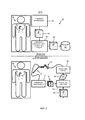
На фиг.1 проиллюстрирован пример варианта осуществления роботизированной направляющей системы в соответствии с настоящим изобретением.1 illustrates an example embodiment of a robotic guide system in accordance with the present invention.
На фиг.2 проиллюстрирована блок-схема, представляющая пример варианта осуществления способа роботизированного направления в соответствии с настоящим изобретением.2 is a flowchart showing an example of an embodiment of a robotic direction method in accordance with the present invention.
На фиг.3 проиллюстрирован пример хирургической реализации блок-схемы, представленной на фиг.2.Figure 3 illustrates an example of a surgical implementation of the flowchart of figure 2.
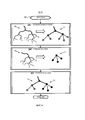
На фиг.4 проиллюстрирована блок-схема, представляющая пример варианта осуществления способа сопоставления графов в соответствии с настоящим изобретением.4 is a flowchart showing an example of an embodiment of a graph matching method in accordance with the present invention.
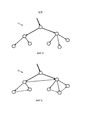
На фиг.5 и 6 проиллюстрирован пример упорядочения основных графов сети кровеносных сосудов в соответствии с настоящим изобретением.Figures 5 and 6 illustrate an example of ordering the main graphs of a blood vessel network in accordance with the present invention.
На фиг.7 проиллюстрирован пример результата наложения геометрического представления на эндоскопическое изображение в соответствии с настоящим изобретением.7 illustrates an example of the result of superimposing a geometric representation on an endoscopic image in accordance with the present invention.
На фиг.8 проиллюстрирован пример траектории движения робота в пределах результата наложения, представленного на фиг.7, в соответствии с настоящим изобретением.On Fig illustrates an example of the trajectory of the robot within the overlap result shown in Fig.7, in accordance with the present invention.
Как показано на фиг.1, в роботизированной направляющей системе используют роботизированный блок 10 и блок 20 управления для какой-либо эндоскопической процедуры, включающей эндоскопическую визуализацию сети кровеносных сосудов, имеющей одно или несколько разветвлений (т.е. ветвей). Примеры таких эндоскопических процедур включают, но без ограничения, минимально инвазивное кардиологическое хирургическое вмешательство (например, трансплантацию шунта коронарных артерий или замену митрального клапана).As shown in FIG. 1, in a robotic guiding system, a
Роботизированный блок 10 содержит робота 11, эндоскоп 12, жестко прикрепленный к роботу 11, и устройство 13 захвата видео, прикрепленное к эндоскопу 12.The
Робот 11 широко определен в настоящем описании в качестве какого-либо роботизированного устройства, структурно сконфигурированного с механическим приводным управлением одним или несколькими сочленениями для манипулирования рабочим органом, по желанию, для конкретной эндоскопической процедуры. На практике робот 11 может иметь четыре (4) степени свободы, такой как, например, последовательный робот, имеющий сочленения, последовательно соединенные с жесткими сегментами, параллельный робот, имеющий сочленения и жесткие сегменты, установленные в параллельном порядке (например, платформа Стюарта, известная в данной области техники), или какая-либо гибридная комбинация последовательных и параллельных кинематических схем.The
Эндоскоп 12 широко определен в настоящем описании в качестве какого-либо устройства, структурно сконфигурированного с возможностью визуализации изнутри организма. Примеры эндоскопа 12 для целей настоящего изобретения включают, но без ограничения, оптический прибор какого-либо типа, гибкий или жесткий (например, эндоскоп, артроскоп, бронхоскоп, холедохоскоп, колоноскоп, цистоскоп, дуоденоскоп, гастроскоп, гистероскоп, лапароскоп, ларингоскоп, нейроскоп, отоскоп, нажимной энтероскоп, риноларингоскоп, сигмоидоскоп, синускоп, тораскоп и т.д.) и какое-либо устройство, похоженее на оптическое устройство, которое оборудовано системой визуализации (например, вложенная канюля со средством визуализации). Визуализация является локальной, и поверхностные изображения можно получать оптически с использованием волоконной оптики, линз и миниатюризированных (например, на основе CCD) систем визуализации.The
На практике эндоскоп 12 устанавливают на концевом рабочем органе робота 11. Позиция концевого рабочего органа робота 11 представляет собой положение и ориентацию рабочего органа в системе координат приводов робота 11. С эндоскопом 12, установленным на рабочем органе робота 11, какая-либо заданная позиция поля обзора эндоскопа 12 в пределах анатомической области соответствует четкой позиции рабочего органа робота 11 в системе координат робота. Следовательно, каждое отдельное эндоскопическое изображение сети кровеносных сосудов, генерируемое посредством эндоскопа 12, можно связать с соответствующей позицией эндоскопа 12 в пределах анатомической области.In practice, the
Устройство 13 захвата видео широко определено в настоящем описании в качестве какого-либо устройства, структурно сконфигурированного с возможностью преобразования интраоперационного эндоскопического видеосигнала от эндоскопа 12 в машиночитаемую временную последовательность интраоперационного эндоскопического изображения («IOEI») 14. На практике, в устройстве 13 захвата видео можно использовать устройство захвата кадра какого-либо типа для захвата отдельных цифровых неподвижных кадров из интраоперационного эндоскопического видеосигнала.A
Также со ссылкой на фиг.1, блок 20 управления содержит контроллер 21 робота и контроллер 22 эндоскопа.Also with reference to FIG. 1, the
Контроллер 21 робота широко определен в настоящем описании в качестве какого-либо контроллера, структурно сконфигурированного с возможностью предоставления одной или нескольких команд 26 привода робота («RAC») роботу 11 для управления позицией рабочего органа робота 11 по желанию для эндоскопической процедуры. Более конкретно, контроллер 21 робота преобразует команды 25 положения эндоскопа («EPC») от контроллера 22 эндоскопа в команды 26 привода робота. Например, команды 25 положения эндоскопа могут указывать траектории движения эндоскопа, ведущие к желаемому трехмерному положению поля обзора эндоскопа 12 в пределах анатомической области, в соответствии с чем контроллер 21 робота преобразует команду 25 в команды 26, включая ток срабатывания для каждого двигателя робота 11 при необходимости для перемещения эндоскопа 12 в желаемое трехмерное положение.The
Контроллер 22 эндоскопа широко определен в настоящем описании в качестве какого-либо контроллера, структурно сконфигурированного для реализации способа роботизированного направления в соответствии с настоящим изобретением и показанного для примера на фиг.2. С этой целью, контроллер 22 эндоскопа может включать модуль 23 обработки изображения («IPM»), который широко определен в настоящем описании в качестве какого-либо модуля, структурно сконфигурированного для исполнения совмещения изображения анатомического объекта по настоящему изобретению. В частности, совмещение изображения сети кровеносных сосудов реализовано в качестве примера посредством этапов S32 и S33 блок-схемы 30, представленной на фиг.2. Контроллер 22 эндоскопа дополнительно может содержать визуальный сервомодуль («VSM») 24, который широко определен в настоящем описании в качестве какого-либо модуля, структурно сконфигурированного для генерации команд 25 положения эндоскопа, указывающих траекторию движения эндоскопа, который ведет к желаемому трехмерному положению поля обзора эндоскопа 12 в пределах анатомической области. В частности, команды 25 положения эндоскопа получают из совмещения изображения сети кровеносных сосудов, как реализовано в качестве примера посредством этапа S34 блок-схемы 30, представленной на фиг.2.The
Далее в настоящем описании предоставлено описание блок-схемы 30 для того, чтобы облегчить дальнейшее понимание контроллера 22 эндоскопа.Further in the present description, a description of a block diagram 30 is provided in order to facilitate a further understanding of the
Со ссылкой на фиг.2, этап S31 блок-схемы 30 включает извлечение геометрического представления сети кровеносных сосудов из дооперационного трехмерного изображения. Например, как показано на фиг.3, устройство трехмерной визуализации (например, КТ устройство, рентгеновское устройство или МРТ устройство) генерирует дооперационное трехмерное изображение 42 грудной области пациента 50, которое иллюстрирует левую и правую коронарные артерии 51 и 52 пациента 50. После этого устройство 43 извлечения сети кровеносных сосудов извлекает геометрическое представление 44 сети коронарных артерий из изображения 42, которое можно хранить в базе 45 данных. На практике, сканер Brilliance iCT, поставляемый Philips, можно использовать для того, чтобы генерировать изображение 42, и для того, чтобы извлекать трехмерный массив данных сети коронарных артерий из изображения 42.With reference to FIG. 2, step S31 of
Также со ссылкой на фиг.2, этап S32 блок-схемы 30 включает модуль 23 обработки изображения, сопоставляющий графическое представление одного или нескольких интраоперационных эндоскопических изображений 14 (фиг.1) сети кровеносных сосудов с графическим представлением дооперационного трехмерного изображения 44 (фиг.1) сети кровеносных сосудов. Например, как показано на фиг.3, эндоскоп 12 генерирует интраоперационное эндоскопическое видео грудной области пациента 50, которое захватывают посредством устройства 13 захвата видео и преобразуют в интраоперационные эндоскопические изображения 14, в соответствии с чем модуль 23 обработки изображения контроллера 22 эндоскопа сопоставляет графическое представление интраоперационного эндоскопического изображения(й) 14 сети коронарных артерий с графическим представлением дооперационного трехмерного изображения 44 сети коронарных артерий. В одном примере варианта осуществления, модуль 23 обработки изображения исполняет способ сопоставления изображения сети кровеносных сосудов по настоящему изобретению, как представлено для примера блок-схемой 60, показанной на фиг.4, которая описана в настоящем описании в контексте сети кровеносных сосудов, представляющей собой сеть коронарных артерий.Also with reference to FIG. 2, step S32 of
Со ссылкой на фиг.4, этап S61 блок-схемы 60 включает модуль 23 обработки изображения, генерирующий основной граф сети коронарных артерий по геометрическому представлению сети коронарных артерий в соответствии с каким-либо способом представления, известным в данной области техники. Например, как показано на этапе S61, геометрическое представление 70 сети коронарных артерий преобразуют в основной граф 71, имеющий узлы, представляющие каждое разветвление (например, бифуркация или трифуркация) геометрического представления 70 сети коронарных артерий, и дополнительно имеющий соединения ветвей между узлами. Этап S61 можно осуществлять до операции (например, за несколько суток до эндоскопического хирургического вмешательства или за какое-либо время до введения эндоскопа 12 в пациента 50) или во время операции посредством ангиографии с манипулятором C-типа или другой подходящей системы.With reference to FIG. 4, step S61 of
Этап S62 блок-схемы 60 включает в себя модуль 23 обработки изображения, генерирующий подграф сети коронарных артерий из части сети коронарных артерий, видимой на интраоперационном эндоскопическом изображении 14 в соответствии с каким-либо способом графического представления, известным в данной области техники. В частности, эндоскоп 12 вводят внутрь пациента 50, в соответствии с чем модуль 23 обработки изображения осуществляет обнаружение структуры коронарных артерий в пределах интраоперационного эндоскопического изображения 14. На практике, некоторые артериальные структуры могут быть видны, тогда как другие артериальные структуры могут быть скрыты слоем жировой ткани. По существу, модуль 23 обработки изображения может реализовать автоматическое обнаружение видимой структуры(р) коронарных артерий посредством известных операций обработки изображения (например, пороговое обнаружение по отчетливому красному цвету видимой структуры(р) коронарных артерий), или хирург может вручную использовать устройство ввода для того, чтобы очертить видимую структуру(ры) коронарных артерий на дисплее компьютера. После обнаружения артериальной структуры(р), модуль 23 обработки изображения генерирует граф сети коронарных артерий образом, схожим с генерацией основного графа сети коронарных артерий. Например, как показано на этапе S62, геометрическое представление 72 структуры(р) коронарных артерий преобразуют в граф 73, имеющий узлы, представленные для каждого разветвления (например, бифуркации или трифуркации) геометрического представления 72 сети коронарных артерий, и дополнительно имеющий соединения ветвей между узлами. Поскольку обе сети происходят от одного и того же человека, понятно, что граф, полученный из эндоскопических изображений, представляет собой подграф графа, полученного из трехмерных изображений.Step S62 of
Этап S63 блок-схемы 60 включает в себя модуль 23 обработки изображения, сопоставляющий подграф с основным графом в соответствии с каким-либо известным способом сопоставления графов (например, максимально общий подграф или общий подграф Макгрегора). Например, как показано на этапе S63, узлы подграфа 73 сопоставляют с поднабором узлов основного графа 71.Step S63 of
На практике, подграф 73 может быть только частично обнаружен на интраоперационном эндоскопическом изображении 14, или некоторые узлы/соединения подграфа 73 могут отсутствовать на интраоперационном эндоскопическом изображении 14. Чтобы после сопоставления усовершенствовать точность этапа S62, можно реализовать дополнительное упорядочение основного графа 71 и подграфа 73.In practice,
В одном из вариантов осуществления вертикальное упорядочение узлов основного графа 71 реализуют, основываясь на известной ориентации пациента 50 во время сканирования изображения на этапе S61. В частности, узлы основного графа могут быть направленно связаны для сохранения порядка сверху вниз, как показано для примера на фиг.5 сплошными стрелками. Для подграфа 73 ориентация пациента 50 относительно эндоскопа 12 может быть не известна. Однако зная, что диаметр ветвей сети коронарных артерий уменьшается по мере их хода сверху вниз, варьирующие размеры артерий для ветвей артерий на интраоперационном эндоскопическом изображении 14 могут указывать ориентацию.In one embodiment, the vertical ordering of the nodes of the
В другом варианте осуществления горизонтальное упорядочение узлов основного графа 70 можно реализовать, основываясь на известной ориентации пациента 50 во время сканирования изображения на этапе S61. В частности, узлы основного графа могут быть направленно связаны для сохранения упорядочения узлов слева направо, как показано для примера на фиг.6 пунктирными стрелками. Для подграфа 73, скорее всего при неизвестной ориентации пациента 50 относительно эндоскопа 12, горизонтальное упорядочение узлов подграфа 73 может задать оперирующий хирург или ассистент через графический пользовательский интерфейс.In another embodiment, the horizontal ordering of the nodes of the
Несмотря на то что использование упорядочения может уменьшать время сопоставления графов и снижать число возможных сопоставлений, теоретически множественные сопоставления между графами все еще можно получать с помощью алгоритма сопоставления. На такой случай множественных сопоставлений направлен этап S33 блок-схемы 30.Although using ordering can reduce graph matching time and reduce the number of possible comparisons, theoretically multiple comparisons between graphs can still be obtained using the matching algorithm. In such a case of multiple comparisons, step S33 of the
Снова со ссылкой на фиг.2, основываясь на сопоставлении графов, этап S33 блок-схемы включает результат наложения геометрического представления дооперационного трехмерного изображения 44 (фиг.1) сети кровеносных сосудов на интраоперационное эндоскопическое изображение 14 сети кровеносных сосудов. Это выполняют посредством использования геометрического представления, однозначно ассоциированного с основным графом. Таким образом, всю геометрию можно непосредственно перевести в интраоперационное эндоскопическое изображение 14 с использованием перспективного преобразования. Перспективное преобразование можно обнаруживать по интраоперационному эндоскопическому изображению 14 и узлам в дооперационном трехмерном изображении 44 с использованием алгоритмов сопоставления, известных в данной области, таких как, например, гомографическое сопоставление.Again with reference to FIG. 2, based on the comparison of the graphs, step S33 of the flowchart includes the result of superimposing a geometric representation of the preoperative three-dimensional image 44 (FIG. 1) of the blood vessel network onto the intraoperative
Например, на фиг.7 проиллюстрировано геометрическое представление 80 сети коронарных артерий, которое имеет узлы, сопоставленные с узлами 91-95 с использованием интраоперационного эндоскопического изображения 90. Расстояние между каждой парой узлов среди узлов 91-95 можно использовать для того, чтобы определять коэффициент пересчета для геометрического представления 80, чтобы тем самым сделать возможным наложение геометрического представления 80 на интраоперационное эндоскопическое изображение 90, как показано.For example, FIG. 7 illustrates a
На практике, если сопоставление графов на этапе S32 (фиг.2) приносит множество результатов, то все возможные результаты наложения можно отображать хирургу, в соответствии с чем хирург может выбирать результат сопоставления, который хирург полагает наиболее вероятным сопоставлением, через графический пользовательский интерфейс. При условии что хирург знает положение эндоскопа 12 относительно по меньшей мере некоторых структур на интраоперационном эндоскопическом изображении 14, выбор может быть относительно простым.In practice, if the comparison of graphs in step S32 (Fig. 2) yields a lot of results, then all possible overlay results can be displayed to the surgeon, according to which the surgeon can select the result of the comparison, which the surgeon considers the most probable comparison, through the graphical user interface. Provided that the surgeon knows the position of the
Также со ссылкой на фиг.2, этап S34 блок-схемы 30 включает генерацию траектории движения эндоскопа визуальным сервомодулем 32 в пределах результата наложения геометрического представления дооперационного трехмерного изображения 44 (фиг.1) сети кровеносных сосудов на интраоперационное эндоскопическое изображение 14 (фиг.1) сети кровеносных сосудов. Основываясь на траектории движения эндоскопа, визуальный сервомодуль 32 генерирует команды 25 положения эндоскопа для контроллера 21 робота, чтобы тем самым направлять эндоскоп 12 (фиг.1) вдоль траектории движения эндоскопа в желаемое положение в пределах анатомической области. В частности, после того как находят точный результат наложения, роботу 11 можно давать команду направлять эндоскоп 12 в положения, которые хирург выбирает на дооперационном трехмерном изображении 44. Хирург или ассистент может выбирать точку сети кровеносных сосудов, и робот 11 может направлять эндоскоп 12 в это желаемое положение вдоль какой-либо подходящей траектории движения. Например, как показано на фиг.9, робот 11 может перемещать эндоскоп 12 вдоль кратчайшей траектории 101 движения в желаемое положение 100 или вдоль траектории движения по коронарным артериям 102 в желаемое положение 100. Траектория движения по коронарным артериям 102 представляет собой предпочтительный вариант осуществления, поскольку траектория движения по коронарным артериям 102 позволяет хирургу наблюдать видимые артерии по мере перемещения эндоскопа 12 роботом 11. Вдобавок, это может помогать хирургу принимать решение, если сопоставление было успешным. Траекторию движения по коронарным артериям 102 можно определять с использованием способов, известных в области техники (например, алгоритм кратчайшей траектории движения Дейкстры).Also with reference to FIG. 2, step S34 of
На практике, перемещением робота 11 можно командовать с использованием некалиброванного визуального сервоуправления с удаленным центром движения, и поле обзора эндоскопа 12 можно расширять для того, чтобы дать возможность для большего подграфа во время этапа сопоставления S32.In practice, the movement of the
Также со ссылкой на фиг.2, этапы S32-S34 можно исполнять или за один раз или на периодической основе до тех пор, пока робот 11 не переместит эндоскоп 12 в желаемое положение в пределах анатомической области, или множество раз, как определяет хирург.Also with reference to FIG. 2, steps S32-S34 can be performed either at one time or on a periodic basis until the
На практике, модули 23 и 24 (фиг.1) можно реализовать посредством аппаратного обеспечения, программного обеспечения и/или встроенного программного обеспечения, интегрированного в контроллер 22 эндоскопа, как показано.In practice,
По описанию фиг. 1-8 в настоящем описании средние специалисты в данной области оценят множество преимуществ настоящего изобретения, включая в качестве неограничивающих примеров применение по настоящему изобретению к эндоскопическому хирургическому вмешательству какого-либо типа, осуществляемому на кровеносных сосудах какого-либо типа.As described in FIG. 1-8 in the present description, those of ordinary skill in the art will appreciate the many advantages of the present invention, including, but not limited to, the application of the present invention to any type of endoscopic surgery performed on any type of blood vessel.
Несмотря на то что настоящее изобретение описано со ссылкой на представленные в качестве примера аспекты, признаки и реализации, раскрытые системы и способы не ограничены такими представленными в качестве примера аспектами, признаками и/или реализациями. Скорее, как будет очевидно специалистам в данной области из предоставленного описания, раскрытые системы и способы допускают модификации, изменения и расширения, не отступая от сущности или объема настоящего изобретения. Соответственно, настоящее изобретение в явной форме включает такие модификации, изменения и расширения в свой объем.Although the present invention has been described with reference to exemplary aspects, features and implementations, the disclosed systems and methods are not limited to such exemplary aspects, features and / or implementations. Rather, as will be apparent to those skilled in the art from the description provided, the disclosed systems and methods are capable of modification, alteration, and expansion without departing from the spirit or scope of the present invention. Accordingly, the present invention explicitly includes such modifications, changes and extensions to its scope.
Claims (20)
роботизированный блок (10), содержащий эндоскоп (12), выполненный с возможностью генерации интраоперационного эндоскопического изображения (14) сети кровеносных сосудов в пределах анатомической области, и робота (11), выполненного с возможностью перемещения эндоскопа (12) в пределах анатомической области; и
блок (20) управления, содержащий контроллер (22) эндоскопа, выполненный с возможностью генерации траектории движения эндоскопа в пределах анатомической области, причем траекторию движения эндоскопа извлекают из сопоставления графического представления интраоперационного эндоскопического изображения (14) сети кровеносных сосудов с графическим представлением дооперационного трехмерного изображения (44) сети кровеносных сосудов, и контроллер (21) робота, выполненный с возможностью выдачи команды роботу (11) на перемещение эндоскопа (12) в пределах анатомической области в соответствии с траекторией движения эндоскопа.1. A robotic guiding system comprising:
a robot unit (10) containing an endoscope (12) configured to generate an intraoperative endoscopic image (14) of a network of blood vessels within the anatomical region, and a robot (11) configured to move the endoscope (12) within the anatomical region; and
a control unit (20) comprising an endoscope controller (22) configured to generate an endoscope trajectory within the anatomical region, the endoscope trajectory being extracted from a comparison of a graphical representation of an intraoperative endoscopic image (14) of a blood vessel network with a graphical representation of a preoperative three-dimensional image ( 44) a network of blood vessels, and a controller (21) of the robot, configured to issue a command to the robot (11) to move the endoscope (12) in crystals anatomical region in accordance with the trajectory of the movement of the endoscope.
генерацию основного графа, получаемого из геометрического представления дооперационного трехмерного изображения (44) сети кровеносных сосудов;
генерацию подграфа, получаемого из геометрического представления интраоперационного эндоскопического изображения (14) сети кровеносных сосудов; и
сопоставление подграфа с основным графом.2. The robotic guiding system according to claim 1, wherein comparing the graphical representation of the intraoperative endoscopic image (14) of the blood vessel network with the graphical representation of the preoperative three-dimensional image (44) of the blood vessel network includes:
generation of the main graph obtained from the geometric representation of the preoperative three-dimensional image (44) of the blood vessel network;
generating a subgraph obtained from a geometric representation of an intraoperative endoscopic image (14) of a network of blood vessels; and
mapping a subgraph to a main graph.
в которой основной граф содержит основной набор узлов, представляющих каждое разветвление сети кровеносных сосудов в пределах дооперационного трехмерного изображения (44) сети кровеносных сосудов; и
подграф содержит поднабор основного набора узлов, причем поднабор узлов представляет каждое разветвление сети кровеносных сосудов в пределах интраоперационного эндоскопического изображения (14) сети кровеносных сосудов.3. The robotic guide system according to claim 2,
in which the main graph contains a basic set of nodes representing each branching of the blood vessel network within the preoperative three-dimensional image (44) of the blood vessel network; and
the subgraph contains a subset of the basic set of nodes, and the subset of nodes represents each branching of the blood vessel network within the intraoperative endoscopic image (14) of the blood vessel network.
установление по меньшей мере одного из вертикального упорядочения и горизонтального упорядочения узлов в основном графе.4. The robotic guiding system according to claim 3, in which the comparison of the subgraph with the main graph includes:
the establishment of at least one of the vertical ordering and horizontal ordering of nodes in the main graph.
в которой сопоставление подграфа с основным графом включает множество результатов сопоставления поднабора узлов с основным набором узлов; и
один из множества результатов сопоставления выбирается в качестве сопоставления подграфа с основным графом.7. The robotic guiding system according to claim 2,
in which the comparison of the subgraph with the main graph includes many results of matching the subset of nodes with the main set of nodes; and
one of the many results of the comparison is selected as a comparison of the subgraph with the main graph.
контроллер (22) эндоскопа, выполненный с возможностью генерации траектории движения эндоскопа в пределах анатомической области, причем траекторию движения эндоскопа извлекают из сопоставления графического представления интраоперационного эндоскопического изображения (14) сети кровеносных сосудов с графическим представлением дооперационного трехмерного изображения (44) сети кровеносных сосудов; и
контроллер (21) робота, выполненный с возможностью выдачи команды роботу (11) на перемещение эндоскопа (12) в пределах анатомической области в соответствии с траекторией движения эндоскопа.9. The control unit (20) for an endoscope (12) configured to generate an intraoperative endoscopic image (14) of a network of blood vessels within the anatomical region, and for a robot (11) configured to move the endoscope (12) within the anatomical region while the control unit (20) contains:
an endoscope controller (22) configured to generate an endoscope trajectory within the anatomical region, wherein the endoscope trajectory is extracted from a comparison of a graphical representation of an intraoperative endoscopic image (14) of a blood vessel network with a graphical representation of a preoperative three-dimensional image (44) of a blood vessel network; and
the controller (21) of the robot, configured to issue a command to the robot (11) to move the endoscope (12) within the anatomical region in accordance with the trajectory of the endoscope.
генерацию основного графа, получаемого из геометрического представления дооперационного трехмерного изображения (44) сети кровеносных сосудов;
генерацию подграфа, получаемого из геометрического представления интраоперационного эндоскопического изображения (14) сети кровеносных сосудов; и
сопоставление подграфа с основным графом.10. The control unit (20) according to claim 9, in which the comparison of the graphic representation of the intraoperative endoscopic image (14) of the blood vessel network with the graphic representation of the preoperative three-dimensional image (44) of the blood vessel network includes:
generation of the main graph obtained from the geometric representation of the preoperative three-dimensional image (44) of the blood vessel network;
generating a subgraph obtained from a geometric representation of an intraoperative endoscopic image (14) of a network of blood vessels; and
mapping a subgraph to a main graph.
в котором основной граф содержит основной набор узлов, представляющих каждое разветвление сети кровеносных сосудов в пределах дооперационного трехмерного изображения (44) сети кровеносных сосудов; и
подграф содержит поднабор основного набора узлов, причем поднабор узлов представляет каждое разветвление сети кровеносных сосудов в пределах интраоперационного эндоскопического изображения (14) сети кровеносных сосудов.11. The control unit (20) according to claim 10,
in which the main graph contains a basic set of nodes representing each branching of the blood vessel network within the preoperative three-dimensional image (44) of the blood vessel network; and
the subgraph contains a subset of the basic set of nodes, and the subset of nodes represents each branching of the blood vessel network within the intraoperative endoscopic image (14) of the blood vessel network.
установление по меньшей мере одного из вертикального упорядочения и горизонтального упорядочения узлов в основном графе.12. The control unit (20) according to claim 11, in which the comparison of the subgraph with the main graph contains:
the establishment of at least one of the vertical ordering and horizontal ordering of nodes in the main graph.
в котором сопоставление подграфа с основным графом включает множество результатов сопоставления поднабора узлов с основным набором узлов; и
один из множества результатов сопоставления выбирают в качестве сопоставления подграфа с основным графом.15. The control unit according to claim 10,
in which the comparison of the subgraph with the main graph includes many results of matching the subset of nodes with the main set of nodes; and
one of the many comparison results is selected as the comparison of the subgraph with the main graph.
генерируют интраоперационное эндоскопическое изображение (14) сети кровеносных сосудов в пределах анатомической области;
генерируют траекторию движения эндоскопа в пределах анатомической области, причем траекторию движения эндоскопа извлекают из сопоставления графического представления интраоперационного эндоскопического изображения (14) сети кровеносных сосудов с графическим представлением дооперационного трехмерного изображения (44) сети кровеносных сосудов; и
выдают команду роботу (11) на перемещение эндоскопа (12) в пределах анатомической области в соответствии с траекторией движения эндоскопа.16. A method for guiding a robot, comprising the steps of:
generating an intraoperative endoscopic image (14) of a network of blood vessels within the anatomical region;
generate the trajectory of the endoscope within the anatomical region, and the trajectory of the endoscope is extracted from a comparison of the graphical representation of the intraoperative endoscopic image (14) of the blood vessel network with the graphic representation of the preoperative three-dimensional image (44) of the blood vessel network; and
give a command to the robot (11) to move the endoscope (12) within the anatomical region in accordance with the trajectory of the endoscope.
генерируют основной граф, полученный из геометрического представления дооперационного трехмерного изображения (44) сети кровеносных сосудов;
генерируют подграф, полученный из геометрического представления интраоперационного эндоскопического изображения (14) сети кровеносных сосудов; и
сопоставляют подграф с основным графом.17. The method for guiding a robot according to claim 16, wherein comparing a graphical representation of an intraoperative endoscopic image (14) of a blood vessel network with a graphical representation of a preoperative three-dimensional image (44) of a blood vessel network includes the steps of:
generate the main graph obtained from the geometric representation of the preoperative three-dimensional image (44) of the network of blood vessels;
generating a subgraph obtained from the geometric representation of the intraoperative endoscopic image (14) of the blood vessel network; and
match the subgraph to the main graph.
в котором основной граф содержит основной набор узлов, представляющих каждое разветвление сети кровеносных сосудов в пределах дооперационного трехмерного изображения (44) сети кровеносных сосудов; и
подграф содержит поднабор основного набора узлов, причем поднабор узлов представляет каждое разветвление сети кровеносных сосудов в пределах интраоперационного эндоскопического изображения (14) сети кровеносных сосудов.18. The method of directing the robot according to claim 17,
in which the main graph contains a basic set of nodes representing each branching of the blood vessel network within the preoperative three-dimensional image (44) of the blood vessel network; and
the subgraph contains a subset of the basic set of nodes, and the subset of nodes represents each branching of the blood vessel network within the intraoperative endoscopic image (14) of the blood vessel network.
накладывают геометрическое представление дооперационного трехмерного изображения (44) сети кровеносных сосудов на интраоперационное эндоскопическое изображение (14) сети кровеносных сосудов в соответствии с сопоставлением графического представления интраоперационного эндоскопического изображения (14) сети кровеносных сосудов с графическим представлением дооперационного трехмерного изображения (44) сети кровеносных сосудов.19. The method of guiding the robot according to claim 17, which further comprises a step in which:
impose a geometric representation of the preoperative three-dimensional image (44) of the blood vessel network on the intraoperative endoscopic image (14) of the blood vessel network in accordance with a comparison of the graphic representation of the intraoperative endoscopic image (14) of the blood vessel network with the graphic representation of the preoperative three-dimensional image (44) of the blood vessel network.
Applications Claiming Priority (3)
| Application Number | Priority Date | Filing Date | Title |
|---|---|---|---|
| US38298010P | 2010-09-15 | 2010-09-15 | |
| US61/382,980 | 2010-09-15 | ||
| PCT/IB2011/053998 WO2012035492A1 (en) | 2010-09-15 | 2011-09-13 | Robotic control of an endoscope from blood vessel tree images |
Publications (2)
| Publication Number | Publication Date |
|---|---|
| RU2013116901A RU2013116901A (en) | 2014-10-20 |
| RU2594813C2 true RU2594813C2 (en) | 2016-08-20 |
Family
ID=44736002
Family Applications (1)
| Application Number | Title | Priority Date | Filing Date |
|---|---|---|---|
| RU2013116901/14A RU2594813C2 (en) | 2010-09-15 | 2011-09-13 | Robot control for an endoscope from blood vessel tree images |
Country Status (7)
| Country | Link |
|---|---|
| US (2) | US9615886B2 (en) |
| EP (1) | EP2615993B1 (en) |
| JP (1) | JP5955847B2 (en) |
| CN (1) | CN103108602B (en) |
| BR (1) | BR112013005879A2 (en) |
| RU (1) | RU2594813C2 (en) |
| WO (1) | WO2012035492A1 (en) |
Families Citing this family (47)
| Publication number | Priority date | Publication date | Assignee | Title |
|---|---|---|---|---|
| JP6122875B2 (en) | 2012-02-06 | 2017-04-26 | コーニンクレッカ フィリップス エヌ ヴェKoninklijke Philips N.V. | Detection of invisible branches in blood vessel tree images |
| US10039473B2 (en) | 2012-05-14 | 2018-08-07 | Intuitive Surgical Operations, Inc. | Systems and methods for navigation based on ordered sensor records |
| KR102214145B1 (en) * | 2012-05-14 | 2021-02-09 | 인튜어티브 서지컬 오퍼레이션즈 인코포레이티드 | Systems and methods for registration of a medical device using a reduced search space |
| US11786324B2 (en) | 2012-06-21 | 2023-10-17 | Globus Medical, Inc. | Surgical robotic automation with tracking markers |
| US11857266B2 (en) | 2012-06-21 | 2024-01-02 | Globus Medical, Inc. | System for a surveillance marker in robotic-assisted surgery |
| US11864839B2 (en) | 2012-06-21 | 2024-01-09 | Globus Medical Inc. | Methods of adjusting a virtual implant and related surgical navigation systems |
| US11399900B2 (en) | 2012-06-21 | 2022-08-02 | Globus Medical, Inc. | Robotic systems providing co-registration using natural fiducials and related methods |
| US11298196B2 (en) | 2012-06-21 | 2022-04-12 | Globus Medical Inc. | Surgical robotic automation with tracking markers and controlled tool advancement |
| US11253327B2 (en) | 2012-06-21 | 2022-02-22 | Globus Medical, Inc. | Systems and methods for automatically changing an end-effector on a surgical robot |
| US11793570B2 (en) | 2012-06-21 | 2023-10-24 | Globus Medical Inc. | Surgical robotic automation with tracking markers |
| US10874466B2 (en) | 2012-06-21 | 2020-12-29 | Globus Medical, Inc. | System and method for surgical tool insertion using multiaxis force and moment feedback |
| US10624710B2 (en) | 2012-06-21 | 2020-04-21 | Globus Medical, Inc. | System and method for measuring depth of instrumentation |
| US11864745B2 (en) | 2012-06-21 | 2024-01-09 | Globus Medical, Inc. | Surgical robotic system with retractor |
| US11896446B2 (en) | 2012-06-21 | 2024-02-13 | Globus Medical, Inc | Surgical robotic automation with tracking markers |
| US11589771B2 (en) | 2012-06-21 | 2023-02-28 | Globus Medical Inc. | Method for recording probe movement and determining an extent of matter removed |
| US11963755B2 (en) | 2012-06-21 | 2024-04-23 | Globus Medical Inc. | Apparatus for recording probe movement |
| US11045267B2 (en) | 2012-06-21 | 2021-06-29 | Globus Medical, Inc. | Surgical robotic automation with tracking markers |
| US11857149B2 (en) | 2012-06-21 | 2024-01-02 | Globus Medical, Inc. | Surgical robotic systems with target trajectory deviation monitoring and related methods |
| US10842461B2 (en) | 2012-06-21 | 2020-11-24 | Globus Medical, Inc. | Systems and methods of checking registrations for surgical systems |
| US11317971B2 (en) | 2012-06-21 | 2022-05-03 | Globus Medical, Inc. | Systems and methods related to robotic guidance in surgery |
| EP2866638B1 (en) * | 2012-06-28 | 2019-12-04 | Koninklijke Philips N.V. | Enhanced visualization of blood vessels using a robotically steered endoscope |
| CN104427926B (en) | 2012-06-28 | 2017-09-08 | 皇家飞利浦有限公司 | Assessment using the photo-plethysmographic on endoscopic images to patency |
| US10194801B2 (en) | 2012-06-28 | 2019-02-05 | Koninklijke Philips N.V. | Fiber optic sensor guided navigation for vascular visualization and monitoring |
| JP6301332B2 (en) * | 2012-08-14 | 2018-03-28 | インテュイティブ サージカル オペレーションズ, インコーポレイテッド | System and method for registration of multiple vision systems |
| RU2692206C2 (en) * | 2013-05-09 | 2019-06-21 | Конинклейке Филипс Н.В. | Robotic control of endoscope based on anatomical features |
| EP3041409A1 (en) * | 2013-09-06 | 2016-07-13 | Koninklijke Philips N.V. | Navigation system |
| CN105934216B (en) * | 2014-01-24 | 2019-09-17 | 皇家飞利浦有限公司 | Robot guides system, control unit and device |
| EP3102141B1 (en) | 2014-02-04 | 2019-08-14 | Koninklijke Philips N.V. | A system for visualising an anatomical target |
| US10772684B2 (en) | 2014-02-11 | 2020-09-15 | Koninklijke Philips N.V. | Spatial visualization of internal mammary artery during minimally invasive bypass surgery |
| EP3125808B1 (en) | 2014-03-28 | 2023-01-04 | Intuitive Surgical Operations, Inc. | Quantitative three-dimensional visualization of instruments in a field of view |
| EP3125809B1 (en) | 2014-03-28 | 2020-09-09 | Intuitive Surgical Operations, Inc. | Surgical system with haptic feedback based upon quantitative three-dimensional imaging |
| WO2015149043A1 (en) | 2014-03-28 | 2015-10-01 | Dorin Panescu | Quantitative three-dimensional imaging and printing of surgical implants |
| JP6609616B2 (en) | 2014-03-28 | 2019-11-20 | インテュイティブ サージカル オペレーションズ, インコーポレイテッド | Quantitative 3D imaging of surgical scenes from a multiport perspective |
| WO2015149040A1 (en) | 2014-03-28 | 2015-10-01 | Dorin Panescu | Quantitative three-dimensional imaging of surgical scenes |
| WO2016137612A1 (en) * | 2015-02-26 | 2016-09-01 | Covidien Lp | Robotically controlling remote center of motion with software and guide tube |
| EP3397187A1 (en) | 2015-12-30 | 2018-11-07 | Koninklijke Philips N.V. | Image based robot guidance |
| US11883217B2 (en) | 2016-02-03 | 2024-01-30 | Globus Medical, Inc. | Portable medical imaging system and method |
| EP3500406B1 (en) | 2016-08-22 | 2021-12-01 | Canon Kabushiki Kaisha | Continuum robot and control method of continuum robot |
| US9931025B1 (en) * | 2016-09-30 | 2018-04-03 | Auris Surgical Robotics, Inc. | Automated calibration of endoscopes with pull wires |
| EP3551117A1 (en) | 2016-12-07 | 2019-10-16 | Koninklijke Philips N.V. | Image guided motion scaling for robot control |
| US11123139B2 (en) * | 2018-02-14 | 2021-09-21 | Epica International, Inc. | Method for determination of surgical procedure access |
| US10430949B1 (en) * | 2018-04-24 | 2019-10-01 | Shenzhen Keya Medical Technology Corporation | Automatic method and system for vessel refine segmentation in biomedical images using tree structure based deep learning model |
| CN110575255B (en) * | 2018-06-07 | 2022-08-16 | 格罗伯斯医疗有限公司 | Robotic system and related methods for providing co-registration using natural fiducials |
| WO2020110278A1 (en) * | 2018-11-30 | 2020-06-04 | オリンパス株式会社 | Information processing system, endoscope system, trained model, information storage medium, and information processing method |
| USD1022197S1 (en) | 2020-11-19 | 2024-04-09 | Auris Health, Inc. | Endoscope |
| WO2023101968A1 (en) | 2021-11-30 | 2023-06-08 | Endoquest Robotics, Inc. | Steerable overtube assemblies for robotic surgical systems |
| WO2023148812A1 (en) * | 2022-02-01 | 2023-08-10 | 日本電気株式会社 | Image processing device, image processing method, and storage medium |
Citations (2)
| Publication number | Priority date | Publication date | Assignee | Title |
|---|---|---|---|---|
| FR2855292A1 (en) * | 2003-05-22 | 2004-11-26 | Inst Nat Rech Inf Automat | Magnetic resonance image pattern readjusting device for use during tele-surgery, has processing unit to readjust selected pattern of portion of image at selected angle at which image is captured based on designed attribute |
| RU2290055C2 (en) * | 2004-04-06 | 2006-12-27 | Государственное образовательное учреждение высшего профессионального образования Новосибирская государственная медицинская академия Министерства здравоохранения Российской Федерации | Neuronavigation endoscopic system |
Family Cites Families (17)
| Publication number | Priority date | Publication date | Assignee | Title |
|---|---|---|---|---|
| JPH08164148A (en) * | 1994-12-13 | 1996-06-25 | Olympus Optical Co Ltd | Surgical operation device under endoscope |
| US20020193686A1 (en) * | 2000-01-10 | 2002-12-19 | Pinhas Gilboa | Methods and systems for performing medical procedures with reference to projective image and with respect to pre-stored images |
| US6610007B2 (en) * | 2000-04-03 | 2003-08-26 | Neoguide Systems, Inc. | Steerable segmented endoscope and method of insertion |
| JP4656700B2 (en) * | 2000-07-11 | 2011-03-23 | オリンパス株式会社 | Endoscopic surgery system |
| EP1499235B1 (en) * | 2002-04-17 | 2016-08-17 | Covidien LP | Endoscope structures and techniques for navigating to a target in branched structure |
| US7822461B2 (en) * | 2003-07-11 | 2010-10-26 | Siemens Medical Solutions Usa, Inc. | System and method for endoscopic path planning |
| US7646903B2 (en) * | 2005-06-22 | 2010-01-12 | Siemens Medical Solutions Usa, Inc. | System and method for path based tree matching |
| US20070167784A1 (en) * | 2005-12-13 | 2007-07-19 | Raj Shekhar | Real-time Elastic Registration to Determine Temporal Evolution of Internal Tissues for Image-Guided Interventions |
| US7804990B2 (en) | 2006-01-25 | 2010-09-28 | Siemens Medical Solutions Usa, Inc. | System and method for labeling and identifying lymph nodes in medical images |
| US20090156895A1 (en) * | 2007-01-31 | 2009-06-18 | The Penn State Research Foundation | Precise endoscopic planning and visualization |
| US8672836B2 (en) | 2007-01-31 | 2014-03-18 | The Penn State Research Foundation | Method and apparatus for continuous guidance of endoscopy |
| US9037215B2 (en) * | 2007-01-31 | 2015-05-19 | The Penn State Research Foundation | Methods and apparatus for 3D route planning through hollow organs |
| WO2008111070A2 (en) * | 2007-03-12 | 2008-09-18 | David Tolkowsky | Devices and methods for performing medical procedures in tree-like luminal structures |
| DE102008016146B4 (en) | 2008-03-28 | 2010-01-28 | Aktormed Gmbh | Operation assistance system for guiding a surgical auxiliary instrument |
| JP5372406B2 (en) | 2008-05-23 | 2013-12-18 | オリンパスメディカルシステムズ株式会社 | Medical equipment |
| JP5572440B2 (en) * | 2009-09-15 | 2014-08-13 | 富士フイルム株式会社 | Diagnosis support system, diagnosis support program, and diagnosis support method |
| EP2605693B1 (en) * | 2010-08-20 | 2019-11-06 | Veran Medical Technologies, Inc. | Apparatus for four dimensional soft tissue navigation |
-
2011
- 2011-09-13 RU RU2013116901/14A patent/RU2594813C2/en active
- 2011-09-13 EP EP11764337.9A patent/EP2615993B1/en active Active
- 2011-09-13 JP JP2013528806A patent/JP5955847B2/en active Active
- 2011-09-13 WO PCT/IB2011/053998 patent/WO2012035492A1/en active Application Filing
- 2011-09-13 US US13/822,001 patent/US9615886B2/en active Active
- 2011-09-13 CN CN201180044480.6A patent/CN103108602B/en active Active
- 2011-09-13 BR BR112013005879A patent/BR112013005879A2/en not_active Application Discontinuation
-
2017
- 2017-04-10 US US15/483,615 patent/US10182704B2/en active Active
Patent Citations (2)
| Publication number | Priority date | Publication date | Assignee | Title |
|---|---|---|---|---|
| FR2855292A1 (en) * | 2003-05-22 | 2004-11-26 | Inst Nat Rech Inf Automat | Magnetic resonance image pattern readjusting device for use during tele-surgery, has processing unit to readjust selected pattern of portion of image at selected angle at which image is captured based on designed attribute |
| RU2290055C2 (en) * | 2004-04-06 | 2006-12-27 | Государственное образовательное учреждение высшего профессионального образования Новосибирская государственная медицинская академия Министерства здравоохранения Российской Федерации | Neuronavigation endoscopic system |
Also Published As
| Publication number | Publication date |
|---|---|
| CN103108602A (en) | 2013-05-15 |
| EP2615993B1 (en) | 2015-03-18 |
| US10182704B2 (en) | 2019-01-22 |
| US20130165948A1 (en) | 2013-06-27 |
| EP2615993A1 (en) | 2013-07-24 |
| US20170209028A1 (en) | 2017-07-27 |
| CN103108602B (en) | 2015-09-30 |
| JP2013541365A (en) | 2013-11-14 |
| JP5955847B2 (en) | 2016-07-20 |
| RU2013116901A (en) | 2014-10-20 |
| BR112013005879A2 (en) | 2016-05-10 |
| WO2012035492A1 (en) | 2012-03-22 |
| US9615886B2 (en) | 2017-04-11 |
Similar Documents
| Publication | Publication Date | Title |
|---|---|---|
| RU2594813C2 (en) | Robot control for an endoscope from blood vessel tree images | |
| EP2747695B1 (en) | Endoscopic registration of vessel tree images | |
| US9280823B2 (en) | Invisible bifurcation detection within vessel tree images | |
| EP3463032B1 (en) | Image-based fusion of endoscopic image and ultrasound images | |
| US10772684B2 (en) | Spatial visualization of internal mammary artery during minimally invasive bypass surgery | |
| RU2692206C2 (en) | Robotic control of endoscope based on anatomical features | |
| JP6382802B2 (en) | Improving blood vessel visualization using a robot-operated endoscope | |
| WO2012156873A1 (en) | Endoscope segmentation correction for 3d-2d image overlay | |
| CN104105439B (en) | Sightless dichotomous detection in vascular tree image |