EP3877802B1 - Projektionsobjektiv mit vier sphärischen glaselementen - Google Patents
Projektionsobjektiv mit vier sphärischen glaselementen Download PDFInfo
- Publication number
- EP3877802B1 EP3877802B1 EP19836107.3A EP19836107A EP3877802B1 EP 3877802 B1 EP3877802 B1 EP 3877802B1 EP 19836107 A EP19836107 A EP 19836107A EP 3877802 B1 EP3877802 B1 EP 3877802B1
- Authority
- EP
- European Patent Office
- Prior art keywords
- lens element
- refractive power
- incident surface
- exiting surface
- glass
- Prior art date
- Legal status (The legal status is an assumption and is not a legal conclusion. Google has not performed a legal analysis and makes no representation as to the accuracy of the status listed.)
- Active
Links
Images


Classifications
-
- G—PHYSICS
- G02—OPTICS
- G02B—OPTICAL ELEMENTS, SYSTEMS OR APPARATUS
- G02B27/00—Optical systems or apparatus not provided for by any of the groups G02B1/00 - G02B26/00, G02B30/00
- G02B27/01—Head-up displays
- G02B27/017—Head mounted
- G02B27/0172—Head mounted characterised by optical features
-
- G—PHYSICS
- G02—OPTICS
- G02B—OPTICAL ELEMENTS, SYSTEMS OR APPARATUS
- G02B9/00—Optical objectives characterised both by the number of the components and their arrangements according to their sign, i.e. + or -
- G02B9/34—Optical objectives characterised both by the number of the components and their arrangements according to their sign, i.e. + or - having four components only
-
- G—PHYSICS
- G02—OPTICS
- G02B—OPTICAL ELEMENTS, SYSTEMS OR APPARATUS
- G02B1/00—Optical elements characterised by the material of which they are made; Optical coatings for optical elements
-
- G—PHYSICS
- G02—OPTICS
- G02B—OPTICAL ELEMENTS, SYSTEMS OR APPARATUS
- G02B13/00—Optical objectives specially designed for the purposes specified below
- G02B13/001—Miniaturised objectives for electronic devices, e.g. portable telephones, webcams, PDAs, small digital cameras
- G02B13/0015—Miniaturised objectives for electronic devices, e.g. portable telephones, webcams, PDAs, small digital cameras characterised by the lens design
- G02B13/005—Miniaturised objectives for electronic devices, e.g. portable telephones, webcams, PDAs, small digital cameras characterised by the lens design having spherical lenses only
-
- G—PHYSICS
- G02—OPTICS
- G02B—OPTICAL ELEMENTS, SYSTEMS OR APPARATUS
- G02B13/00—Optical objectives specially designed for the purposes specified below
- G02B13/16—Optical objectives specially designed for the purposes specified below for use in conjunction with image converters or intensifiers, or for use with projectors, e.g. objectives for projection TV
-
- G—PHYSICS
- G02—OPTICS
- G02B—OPTICAL ELEMENTS, SYSTEMS OR APPARATUS
- G02B27/00—Optical systems or apparatus not provided for by any of the groups G02B1/00 - G02B26/00, G02B30/00
- G02B27/0025—Optical systems or apparatus not provided for by any of the groups G02B1/00 - G02B26/00, G02B30/00 for optical correction, e.g. distorsion, aberration
-
- G—PHYSICS
- G02—OPTICS
- G02B—OPTICAL ELEMENTS, SYSTEMS OR APPARATUS
- G02B27/00—Optical systems or apparatus not provided for by any of the groups G02B1/00 - G02B26/00, G02B30/00
- G02B27/01—Head-up displays
- G02B27/0101—Head-up displays characterised by optical features
-
- G—PHYSICS
- G02—OPTICS
- G02B—OPTICAL ELEMENTS, SYSTEMS OR APPARATUS
- G02B27/00—Optical systems or apparatus not provided for by any of the groups G02B1/00 - G02B26/00, G02B30/00
- G02B27/01—Head-up displays
- G02B27/0101—Head-up displays characterised by optical features
- G02B2027/011—Head-up displays characterised by optical features comprising device for correcting geometrical aberrations, distortion
-
- G—PHYSICS
- G02—OPTICS
- G02B—OPTICAL ELEMENTS, SYSTEMS OR APPARATUS
- G02B27/00—Optical systems or apparatus not provided for by any of the groups G02B1/00 - G02B26/00, G02B30/00
- G02B27/01—Head-up displays
- G02B27/0101—Head-up displays characterised by optical features
- G02B2027/0112—Head-up displays characterised by optical features comprising device for genereting colour display
- G02B2027/0116—Head-up displays characterised by optical features comprising device for genereting colour display comprising devices for correcting chromatic aberration
-
- G—PHYSICS
- G02—OPTICS
- G02B—OPTICAL ELEMENTS, SYSTEMS OR APPARATUS
- G02B27/00—Optical systems or apparatus not provided for by any of the groups G02B1/00 - G02B26/00, G02B30/00
- G02B27/01—Head-up displays
- G02B27/017—Head mounted
- G02B2027/0178—Eyeglass type
-
- G—PHYSICS
- G06—COMPUTING OR CALCULATING; COUNTING
- G06F—ELECTRIC DIGITAL DATA PROCESSING
- G06F3/00—Input arrangements for transferring data to be processed into a form capable of being handled by the computer; Output arrangements for transferring data from processing unit to output unit, e.g. interface arrangements
- G06F3/14—Digital output to display device ; Cooperation and interconnection of the display device with other functional units
Definitions
- the present disclosure relates generally to optical systems suitable for use in near-eye displays.
- a near-eye display can produce a video image, and direct the video image toward a human eye.
- components in an optical system in a near-eye display can be difficult to manufacture and align, due to relatively tight tolerances, and/or expensive, due to relatively expensive manufacturing techniques.
- EP1385023 A1 describes a light guide for display devices of the head-mounted or head-up type. Light passing from a source through an optical system is coupled at a coupling device into the body of the light guide and made visible to an observer by means of an image-extraction grating.
- WO2018/165123 A1 also describes an optical arrangement for use with head-mounted light field displays.
- the arrangement includes a freeform waveguide prism with compound surface and is suitable for use with head-mounted displays with an integral imaging and relay group.
- the invention is an optical system as defined in the appended claims.
- a near-eye display includes a projection lens.
- the projection lens includes four lens elements, each lens element being formed from glass and including spherical or planar incident and exiting surfaces. Compared to a projection lens that uses three lens elements, the four-element projection lens can have relaxed manufactured and alignment tolerances. Unlike a projection lens that uses one or more plastic elements or uses aspherical surfaces, the all-glass projection lens can be manufactured using relatively fast and inexpensive grinding and polishing techniques.
- One or two of the glass lens elements can optionally be formed symmetrically, so as to be reversible.
- One glass element can optionally be plano-convex.
- a right-angle prism can direct light from a video display into the four glass elements.
- An achromatic prism can angularly divert the optical axis by about eight degrees and can direct light out of the four glass elements into a near-eye waveguide.
- the Abbe number (also known as V-number) of a material is defined as defined as the dimensionless quantity (n d - 1) / (n F - n C ), where nd is a refractive index of the material at a wavelength of 587.6 nm (helium d-line), n F is a refractive index of the material at a wavelength of 486.1 nm (hydrogen F-line), and n C is a refractive index of the material at a wavelength of 656.3 nm (hydrogen C-line).
- the higher the Abbe number of a material the lower the dispersion of the material.
- first lens element various optical elements are referred to as first lens element, second lens element, and so forth. It will be understood that the numbering scheme is provided merely for convenience, and to specify an order in which the numbered elements appear. In some examples, one or more additional optical elements can optionally appear between the numbered elements. For example, a planar spectral filter can appear before a first lens element, between a first lens element and a second lens element, between a second lens element and a third lens element, and so forth.
- FIG. 1 shows a schematic view of an optical system 100 suitable for use in a near-eye display, in accordance with some embodiments.
- the configuration of FIG. 1 is but one configuration; other suitable configurations can also be used.
- the optical system 100 includes a controller 102.
- the controller 102 can include circuitry that can convert data representing a video image into an electrical signal.
- the circuitry can include a processor 104.
- the circuitry can include memory 106.
- the memory 106 can include instructions that, when executed by the processor 104, cause the processor 104 to execute instructions.
- the instructions can include processing the electrical signal, storing and accessing stored video content, and the like.
- the controller 102 directs a video signal to the display 108 to be displayed on the display 108 .
- the controller 102 can include a processor 104 on or in the display 108, or can be coupled to a processor 104 away from the display 108 via a wired and/or wireless connection.
- the controller 102 can optionally receive data corresponding to the video signal from an external source, such as a video game console, a laptop or computer connected by a wired or wireless connection, a streaming video source, or others.
- the display 108 can be a liquid crystal on silicon (LCOS) or a digital light processing (DLP) display, in which is illuminated externally.
- the display 108 can display a video image corresponding to die electrical signal.
- a projection lens 110 (discussed in detail below) can project the video image from the display 108 into a near-eye waveguide 112 .
- the near-eye waveguide 112 can guide the projected video image to a location proximate a human eye 114. Light from the waveguide 112 can enter the human eye 114.
- the light can form a reproduced video image on the retina of the human eye 114, which corresponds to the video image displayed on the display 108 and the corresponding electrical signal.
- the elements in FIG. 1 can be packaged as a near-eye display, and can optionally be worn as eyewear, such as spectacles, or as a head-mounted display.
- the projection lens 110 is discussed in detail below.
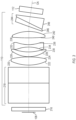
- FIG. 2 shows a side view of an example of an optical system 110 suitable for use in a near-eye display, in accordance with some embodiments.
- FIG. 3 shows a top view of the optical system 110 of FIG. 2 , where the right-angle prism is unfolded for clarity.
- the display 108 can display video, which can include a sequence of images that refreshes at a video rate, such as 30 Hz, 60 Hz, 90 Hz, 120 Hz, or another suitable video rate.
- a video rate such as 30 Hz, 60 Hz, 90 Hz, 120 Hz, or another suitable video rate.
- the display 108 can include an array of pixels, each of which can be independently controlled.
- the display 108 can include sequential color illumination. For example, a red light emitting diode can be activated, and the pixels corresponding to the red portions of the image can be simultaneously activated to the "on" state. Then, a green light emitting diode can be activated, with corresponding pixels, followed by a blue light emitting diode with corresponding pixels. The red, green, and blue illumination and pixel activation can be cycled as needed to form a video image that includes contributions from the red, green, and blue pixels.
- each pixel can include a red light-producing element, a green light-producing element, and a blue light-producing element, each of which are independently controllable to produce a desired intensity (e.g., brightness) and color for each pixel. In some examples, other suitable colors can be used.
- each light-producing element can be a light-emitting diode. In some examples, each light-producing element can be a laser diode. In some examples, each light-producing element can include a white-light source followed by a suitable spectral filter.
- the display 108 can be rectangular, square, oval, or another suitable shape. In some examples, the display 108 be relatively small, such as approximately 3 mm along an edge. Other sizes can also be used.
- the display 108 can optionally be packaged behind a cover glass 216, which is typically a relatively thin glass element.
- the cover glass 216 is intended to protect the display 108 from dust and contamination, and generally does not play an optical role in the system.
- a near-eye waveguide 112 operably guides light toward a human eye 114 ( FIG. 1 ).
- the near-eye waveguide 112 can be shaped as an elongated element having a rectangular or square cross-section that remains constant along a longitudinal length of the near-eye waveguide 112. Other shapes and configurations can also be used for the near-eye waveguide 112.
- the projection lens 110 described below receives light from the display 108 and direct the light into the near-eye waveguide 112. When the near-eye waveguide 112 is positioned suitably close to a human eye 114, the near-eye waveguide 112 can direct the light into the human eye 114.
- a projection lens 110 having a positive total refractive power directs light from the displayed video in a light ray bundle from the display 108 into the near-eye waveguide 112.
- the projection lens 110 has an optical axis (OA) that corresponds to a center of the light ray bundle.
- the projection lens 110 includes a right-angle prism 218 positioned along the optical axis (OA) adjacent the display 108.
- the right-angle prism 218 angularly diverts the optical axis (OA) by ninety degrees.
- the angles can deviate away from the 45 degree/45 degree/90 degree geometry of a true right-angle prism 218, so that the angular diversion can deviate away from ninety degrees.
- Other suitable angular deviations can include ranges between 89 and 91 degrees, between 88 and 92 degrees, between 85 and 95 degrees, and others.
- the right-angle prism 218 can be formed from a crown glass having a refractive index greater than or equal to 1.728 at a wavelength of 587.6 nm and an Abbe number (which measures a glass's dispersion, or its variation in refractive index as a function of wavelength) greater than 50.
- Suitable high-index crown glasses can include H-LAK52, having a refractive index of 1.729 at a wavelength of 587.6 nm and an Abbe number of 54.7. Other suitable high-index crown glasses can also be used.
- the projection lens 110 includes a first lens element 220 positioned along the optical axis (OA) and formed from a first glass having a refractive index between 1.72 and 1.85 at a wavelength of 587.6 nm and an Abbe number between 40 and 55.
- Suitable glasses can include H-LAF50B (having a refractive index of 1.773 at a wavelength of 587.6 nm and an Abbe number of 49.6), KLASKN1, HLAK53B, and others.
- the first lens element 220 has a convex spherical first incident surface 222 facing the right-angle prism 218 and a convex spherical first exiting surface 224 facing away from the display 108.
- the first incident surface 222 and the first exiting surface 224 can have a same radius of curvature, which can simplify a manufacturing process for the first lens element 220.
- the first incident surface 222, the first exiting surface 224, and the first glass can define a refractive power of the first lens element 220 to be positive and between 88% and 128% of the total refractive power, positive and between 112% and 128% of the total refractive power, or in another suitable range.
- the projection lens 110 includes a second lens element 226 positioned along the optical axis (OA) and formed from second glass having a refractive index between 1.72 and 1.85 at a wavelength of 587.6 nm and an Abbe number between 38 and 55.
- Suitable glasses can include H-ZLAF50E (having a refractive index of 1.804 at a wavelength of 587.6 nm and an Abbe number of 46.6), D-ZLAF85L, SLAH59, TAF3D, and others.
- the second lens element 226 has a convex spherical second incident surface 228 facing the first lens element 220 and a concave spherical second exiting surface 230 facing away from the first lens element 220.
- the second incident surface 228, the second exiting surface 230, and the second glass can define a refractive power of the second lens element 226 to be positive and between 35% and 68% of the total refractive power, positive and between 35% and 54% of the total refractive power, or in another suitable range.
- the refractive power of the second lens element 226, divided by the refractive power of the first lens element 220 can be between 0.28 and 0.71, between 0.28 and 0.46, or in another suitable range.
- the projection lens 110 includes a third lens element 232 positioned along the optical axis (OA) and formed from a third glass having a refractive index greater than 1.8 at a wavelength of 587.6 nm and an Abbe number between 20 and 24.
- Suitable glasses can include H-ZF62 (having a refractive index of 1.923 at a wavelength of 587.6 nm and an Abbe number of 20.9), KPSFN1M, and others.
- the third lens element 232 has a concave spherical third incident surface 234 facing the second lens element 226 and a concave spherical third exiting surface 236 facing away from the second lens element 226.
- the third incident surface 234 and the third exiting surface 236 can have a same radius of curvature, which can simplify a manufacturing process for the third lens element 232.
- the third incident surface 234, the third exiting surface 236, and the third glass can define a refractive power of the third lens element 232 to be negative and between 165% and 216% of the total refractive power, negative and between 183% and 216% of the total refractive power, or in another suitable range.
- the projection lens 110 includes a fourth lens element 238 positioned along the optical axis (OA) and formed from a fourth glass having a refractive index greater than 1.85 at a wavelength of 587.6 nm and an Abbe number between 28 and 35.
- Suitable glasses can include H-ZLAF75B (having a refractive index of 1.904 at a wavelength of 587.6 nm and an Abbe number of 31.4), TAFD55, H-ZLAF76, and others.
- the fourth lens element 238 has a convex spherical or planar fourth incident surface 240 facing the third lens element 232 and a convex spherical fourth exiting surface facing away from the third lens element 232 toward the near-eye waveguide 112 .
- the fourth incident surface 240, the fourth exiting surface 242, and the fourth glass can define a refractive power of the fourth lens element 238 to be positive and between 87 % and 125% of the total refractive power, positive and between 91% and 125% of the total refractive power, or in another suitable range.
- the refractive power of the fourth lens element 238, divided by the refractive power of the third lens element 232 can be between -0.64 and -0.49, between -0.60 and -0.49, or in another suitable range.
- the first incident surface 222, the first exiting surface 224, the second incident surface 228, the second exiting surface 230, the third incident surface 234, the third exiting surface 236, die fourth incident surface 240 (for cases in which the fourth incident surface 240 is spherical, e.g., non-planar), and the fourth exiting surface 242 have centers that are collinear along the optical axis (OA). Specifically, each of these surfaces can have a vertex that intersects the optical axis (OA).
- the glass materials for the first lens element 220, the second lens element 226, the third lens element 232, the fourth lens element 238, and the right-angle prism 218 can be selected to reduce or minimize chromatic aberration, at a system level (e.g., one or more elements having a positive chromatic aberration, one or more elements have a negative chromatic aberration, and the net summed chromatic aberration being at or close to zero), for light passing through these elements.
- a system level e.g., one or more elements having a positive chromatic aberration, one or more elements have a negative chromatic aberration, and the net summed chromatic aberration being at or close to zero
- the projection lens 110 includes an achromatic prism 244 positioned along the optical axis (OA) between the fourth lens element 238 and the near-eye waveguide 112.
- the achromatic prism 244 can angularly divert the optical axis (OA) by an angle between seven degrees and nine degrees, such as eight degrees.
- Other suitable angular diversions can also be used, such as a range between six degrees and ten degrees, between three degrees and thirteen degrees, and others.
- the achromatic prism 244 can be formed from a first prism element 246, facing the fourth lens element 238, in contact with a second prism element 248, facing the near-eye waveguide 112.
- the first prism element 246 can be formed from a flint glass having a refractive index between 1.85 and 2.01 at a wavelength of 587.6 nm and an Abbe number between 18.0 and 23.8.
- Suitable glasses can include H-ZF52 (having a refractive index of 1.847 at a wavelength of 587.6 nm and an Abbe number of 23.8), P-SF68, H-ZF88, H-ZF72A, H-ZF62, and others.
- the second prism element 248 can be formed from a crown glass having a refractive index of 1.73 at a wavelength of 587.6 nm and an Abbe number of 54.7.
- Suitable glasses can include H-LAK52 (having a refractive index of 1.729 at a wavelength of 587.6 nm and an Abbe number of 54.7), and others.
- the glasses for the first prism element 246 and the second prism element 248 can be selected to reduce or minimize the chromatic aberration of the achromatic prism 244 (e.g., so that the net chromatic aberration of the achromatic prism 244, alone, is zero or a relatively small value).
- the projection lens 110 can operate over a wavelength range of 460 nm to 620 nm, inclusive.
- Other suitable wavelength ranges can also be used, including 400 nm to 700 nm (typically considered to be a full wavelength range of typical human vision), and others.
- the f/# of a lens can quantify the cone of light captured by the lens for a single object point. Specifically, for a single pixel on the display 108, the f7# can characterize the size of the angular range, from the pixel, that is captured by the projection lens 110 . In some examples, f/# can be related to an amount of light captured by the lens. For example, a relatively low t7# means that more light is captured by the lens, and an image formed by the lens is relatively bright. Similarly, a higher f/# means that less light is captured by the lens, and an image formed by the lens is relatively dim. In some examples, the projection lens 110 can operate at an f/# of 2.08, which corresponds to a numerical aperture of 0.24 at the display 108, or a half-angle of about 14 degrees at the display 108. Other suitable values can also be used.
- the field of view of a lens can quantify how much area of an object is captured by the lens. Specifically, the field of view should include all (or nearly all) of the display 108, so that the lens captures light from pixels at the edge of the display 108.
- the projection lens 110 can have a field of view of 25 degrees, diagonal. Other suitable values can also be used.
- the effective focal length is a distance between a rear principal point of a lens and a rear focal point of the lens. Both the rear principal point and the rear focal point are locations in the lens. Both are mathematical constructs, rather than tangible physical elements of a lens.
- the projection lens 110 can have an effective focal length of 8.32 mm. Other suitable values can also be used.
- the distortion of a lens is one measure of how accurately pixel locations are mapped between an object and a corresponding image.
- a square object is mapped to a square image, with the square image having perfectly straight sides.
- it is generally difficult to completely eliminate distortion so a lens designer often attempts to reduce distortion as much as is practical, and expresses a residual distortion as a percentage of an image height.
- the projection lens 110 can have a distortion of 0.75 % at an image height of 1.86 mm. Other suitable values can also be used.
- the telecentricity of a lens can affect a brightness of an image formed by the lens.
- a projection lens 110 with a display that is externally illuminated e.g., a multi-pixel attenuator that attenuates light from a light source
- telecentricity is desirable, so that pixels at the edge of the image are as bright as pixels in the center of the image.
- the projection lens 110 can have a telecentricity of less than 0.5 degree (chief ray angle) at the edge of the image field (e.g., corresponding to a diagonal corner of the display 108 ).
- a quantity related to telecentricity is relative illumination.
- the projection lens 110 can have a relative illumination (relative to a center of the image) of greater than or equal to 80% at an image height of 1.86 mm. Other suitable values can also be used.
- thermal performance of a lens can be important. For example, it can be desirable to manage thermal expansion of the lens materials, and thermal variations in refractive index, so that the lens performance suitably well over a range of temperatures.
- the projection lens 110 can have an athermal operation over a temperature range of seventy degrees. Other suitable values can also be used.
- the exit pupil of the projection lens 110 can be external to the lens elements.
- the exit pupil can be located at or near an area on the near-eye waveguide 112 at which light enters the near-eye waveguide 112.
- the distance between an external aperture stop to a vertex of the exiting surface of the fourth lens element 238 can be between 3.4 mm to 3.6 mm. Other suitable values can also be used.
- a total lens length can represent a distance in air between a vertex of the incident surface of the first lens element 220 and a vertex of the exiting surface of the fourth lens element 238. In some examples, the total lens length can be 6.59 mm. Other suitable values can also be used.
- an object distance can represent a distance in air between the display 108 and a vertex of the first incident surface 222 of the first lens element 220. In some examples, the object distance can be 6.1 mm. Other suitable values can also be used.
- an optical system includes a projection lens having a positive total refractive power and configured to direct light in a light ray bundle from a display into a near-eye waveguide, the projection lens having an optical axis that corresponds to a center of the light ray bundle, the projection lens comprising: a first lens element positioned along the optical axis, the first lens element having a convex spherical first incident surface facing the display and a convex spherical first exiting surface facing away from the display; a second lens element positioned along the optical axis, the second lens element having a convex spherical second incident surface facing the first lens element and a concave spherical second exiting surface facing away from the first lens element; a third lens element positioned along the optical axis, the third lens element having a concave spherical third incident surface facing the second lens element and a concave spherical third exiting surface facing away from the second lens element; and a fourth lens
- the optical system of Example 1 can optionally be further configured such that the first lens element is formed from a first glass having a refractive index between 1.72 and 1.85 at a wavelength of 587.6 nm and an Abbe number between 40 and 55; the second lens element is formed from second glass having a refractive index between 1.72 and 1.85 at a wavelength of 587.6 nm and an Abbe number between 38 and 55; the third lens element is formed from a third glass having a refractive index greater than 1.8 at a wavelength of 587.6 nm and an Abbe number between 20 and 24; and the fourth lens element is formed from a fourth glass having a refractive index greater than 1.85 at a wavelength of 587.6 nm and an Abbe number between 28 and 35.
- Example 3 the optical system of any one of Examples 1-2 can optionally be further configured such that the first incident surface, the first exiting surface, and the first glass define a refractive power of the first lens element to be positive and between 88% and 128% of the total refractive power; the second incident surface, the second exiting surface, and the second glass define a refractive power of the second lens element to be positive and between 35% and 68% of the total refractive power; the third incident surface, the third exiting surface, and the third glass define a refractive power of the third lens element to be negative and between 165% and 216% of the total refractive power; and the fourth incident surface, the fourth exiting surface, and the fourth glass define a refractive power of the fourth lens element to be positive and between 87% and 125% of the total refractive power.
- Example 4 the optical system of any one of Examples 1-3 can optionally be further configured such that the refractive power of the second lens element, divided by the refractive power of the first lens element, is between 0.28 and 0.71; and the refractive power of the fourth lens element, divided by the refractive power of the third lens element, is between -0.64 and -0.49.
- Example 5 the optical system of any one of Examples 1-4 can optionally be further configured such that the first incident surface, the first exiting surface, and the first glass define a refractive power of the first lens element to be positive and between 112% and 128% of the total refractive power; the second incident surface, the second exiting surface, and the second glass define a refractive power of the second lens element to be positive and between 35% and 54% of the total refractive power; the third incident surface, the third exiting surface, and the third glass define a refractive power of the third lens element to be negative and between 183% and 216% of the total refractive power; and the fourth incident surface, the fourth exiting surface, and the fourth glass define a refractive power of the fourth lens element to be positive and between 91% and 125% of the total refractive power.
- Example 6 the optical system of any one of Examples 1-5 can optionally be further configured such that the refractive power of the second lens element, divided by the refractive power of the first lens element, is between 0.28 and 0.46; and the refractive power of the fourth lens element, divided by the refractive power of the third lens element, is between -0.60 and -0.49.
- Example 7 the optical system of any one of Examples 1-6 can optionally be further configured such that he first incident surface and the first exiting surface have a same radius of curvature.
- Example 8 the optical system of any one of Examples 1-7 can optionally be further configured such that the third incident surface and the third exiting surface have a same radius of curvature.
- Example 9 the optical system of any one of Examples 1-8 can optionally be further configured such that the fourth incident surface is planar.
- Example 10 the optical system of any one of Examples 1-9 can optionally further include a display configured to display video and direct light from the displayed video into the projection lens; a controller configured to direct a video signal to the display to be displayed on the display; and a near-eye waveguide configured to receive light from the projection lens and operably guide the received light toward a human eye.
- a display configured to display video and direct light from the displayed video into the projection lens
- a controller configured to direct a video signal to the display to be displayed on the display
- a near-eye waveguide configured to receive light from the projection lens and operably guide the received light toward a human eye.
- Example 1 the optical system of any one of Examples 1-10 is configured such that the projection lens further comprises a right-angle prism positioned along the optical axis between the display and the first lens element, the right-angle prism configured to angularly divert the optical axis by ninety degrees, the right-angle prism can be formed from a crown glass having a refractive index greater than or equal to 1.728 at a wavelength of 587.6 nm and an Abbe number greater than 50.
- Example 12 the optical system of any one of Examples 1-11 is configured such that the projection lens further comprises an achromatic prism positioned along the optical axis between the near-eye waveguide and the fourth lens element and can be configured to angularly divert the optical axis by an angle between seven degrees and nine degrees.
- Example 13 the optical system of any one of Examples 1-12 can optionally be further configured such that the achromatic prism is formed from a first prism element, facing the fourth lens element, in contact with a second prism element, facing the near-eye waveguide; the first prism is formed from a flint glass having a refractive index between 1.85 and 2.01 at a wavelength of 587.6 nm and an Abbe number between 18.0 and 23.8; and the second prism is formed from a crown glass having a refractive index of 1.73 at a wavelength of 587.6 nm and an Abbe number of 54.7.
- an optical system includes: a projection lens having a positive total refractive power and configured to direct light in a light ray bundle from a display into a near-eye waveguide, the projection lens having an optical axis that corresponds to a center of the light ray bundle, the projection lens comprising: a right-angle prism positioned along the optical axis adjacent the display, the right-angle prism configured to angularly divert the optical axis by ninety degrees; a first lens element positioned along the optical axis, the first lens element having a convex spherical first incident surface facing the right-angle prism and a convex spherical first exiting surface facing away from the display; a second lens element positioned along the optical axis, the second lens element having a convex spherical second incident surface facing the first lens element and a concave spherical second exiting surface facing away from the first lens element; a third lens element positioned along the optical axis, the third optical
- the optical system of Example 14 can optionally be configured such that the right-angle prism is formed from a crown glass having a refractive index greater than or equal to 1.728 at a wavelength of 587.6 nm and an Abbe number greater than 50; the first lens element is formed from a first glass having a refractive index between 1.72 and 1.85 at a wavelength of 587.6 nm and an Abbe number between 40 and 55; the second lens element is formed from second glass having a refractive index between 1.72 and 1.85 at a wavelength of 587.6 nm and an Abbe number between 38 and 55; the third lens element is formed from a third glass having a refractive index greater than 1.8 at a wavelength of 587.6 nm and an Abbe number between 20 and 24; and the fourth lens element is formed from a fourth glass having a refractive index greater than 1.85 at a wavelength of 587.6 nm and an Abbe number between 28 and 35.
- Example 16 the optical system of any one of Examples 14-15 can optionally be configured such that the first incident surface, the first exiting surface, and the first glass define a refractive power of the first lens element to be positive and between 88% and 128% of the total refractive power; the second incident surface, the second exiting surface, and the second glass define a refractive power of the second lens element to be positive and between 35% and 68% of the total refractive power; the third incident surface, the third exiting surface, and the third glass define a refractive power of the third lens element to be negative and between 165% and 216% of the total refractive power; the fourth incident surface, the fourth exiting surface, and the fourth glass define a refractive power of the fourth lens element to be positive and between 87% and 125 % of the total refractive power; the refractive power of the second lens element, divided by the refractive power of the first lens element, is between 0.28 and 0.71; and the refractive power of the fourth lens element, divided by the refractive power of the
- Example 17 the optical system of any one of Examples 14-16 can optionally be configured such that the first incident surface, the first exiting surface, and the first glass define a refractive power of the first lens element to be positive and between 112% and 128% of the total refractive power; the second incident surface, the second exiting surface, and the second glass define a refractive power of the second lens element to be positive and between 35% and 54% of die total refractive power; the third incident surface, die third exiting surface, and die third glass define a refractive power of the third lens element to be negative and between 183% and 216% of the total refractive power; the fourth incident surface, the fourth exiting surface, and the fourth glass define a refractive power of the fourth lens element to be positive and between 91% and 125 % of the total refractive power; the refractive power of the second lens element, divided by die refractive power of the first lens element, is between 0.28 and 0.46; and the refractive power of the fourth lens element, divided by the refractive power of the
- Example 18 the optical system of any one of Examples 14-17 can optionally be configured such that die first incident surface and the first exiting surface have a same radius of curvature; the third incident surface and the third exiting surface have a same radius of curvature; and the fourth incident surface is planar.
- an optical system includes a display configured to display video; a controller configured to direct a video signal to the display to be displayed on the display; a near-eye waveguide configured to operably guide light toward a human eye; a projection lens having a positive total refractive power and configured to direct light from the displayed video in a light ray bundle from the display into the near-eye waveguide, the projection lens having an optical axis that corresponds to a center of the light ray bundle, the projection lens comprising: a right-angle prism positioned along the optical axis adjacent the display, the right-angle prism configured to angularly divert the optical axis by ninety degrees, the right-angle prism being formed from a crown glass having a refractive index greater than or equal to 1.728 at a wavelength of 587.6 nm and an Abbe number greater than 50; a first lens element positioned along the optical axis and formed from a first glass having a refractive index between 1.72 and 1.85 at a wavelength of 5
- the optical system of Example 19 can optionally be configured such that the first incident surface, the first exiting surface, and the first glass define a refractive power of the first lens element to be positive and between 112% and 128% of the total refractive power; die second incident surface, the second exiting surface, and the second glass define a refractive power of the second lens element to be positive and between 35% and 54% of the total refractive power; the third incident surface, the third exiting surface, and the third glass define a refractive power of the third lens element to be negative and between 183% and 216% of the total refractive power; the fourth incident surface, the fourth exiting surface, and the fourth glass define a refractive power of the fourth lens element to be positive and between 91% and 125 % of the total refractive power; the refractive power of the first lens element, divided by the refractive power of the second lens element, is between -0.60 and -0.49; and the refractive power of the third lens element, divided by the refractive power of the second lens
Landscapes
- Physics & Mathematics (AREA)
- General Physics & Mathematics (AREA)
- Optics & Photonics (AREA)
- Lenses (AREA)
- Projection Apparatus (AREA)
- Optical Elements Other Than Lenses (AREA)
Claims (11)
- Ein optisches System, das Folgendes umfasst:eine Anzeige (108), die dazu konfiguriert ist, ein Video anzuzeigen;eine Steuereinheit (102), die dazu konfiguriert ist, ein Videosignal an die Anzeige (108) zu leiten, um auf der Anzeige angezeigt zu werden;einen augennahen Wellenleiter (112), der dazu konfiguriert ist, Licht zu einem menschlichen Auge (114) hin zu führen; undeine Projektionslinse (110), die eine positive Gesamtbrechkraft aufweist und dazu konfiguriert ist, Licht in einem Lichtstrahlbündel von einer Anzeige (108) in einen augennahen Wellenleiter (112) zu leiten, wobei die Projektionslinse eine optische Achse, OA, aufweist, die einem Mittelpunkt des Lichtstrahlbündels entspricht, wobei die Projektionslinse Folgendes umfasst:ein rechtwinkliges Prisma (218), das entlang der optischen Achse neben der Anzeige (108) positioniert ist, wobei das rechtwinklige Prisma (218) dazu konfiguriert ist, die optische Achse winkelig um neunzig Grad abzulenken,ein erstes Linsenelement (220), das entlang der optischen Achse positioniert ist, wobei das erste Linsenelement eine konvexe sphärische erste Einfallfläche (222), die der Anzeige (108) zugewandt ist, und eine konvexe sphärische erste Austrittsfläche (224), die von der Anzeige abgewandt ist, aufweist;ein zweites Linsenelement (226), das entlang der optischen Achse positioniert ist, wobei das zweite Linsenelement eine konvexe sphärische zweite Einfallfläche (228), die dem ersten Linsenelement (220) zugewandt ist, und eine konkave sphärische zweite Austrittsfläche (230), die von dem ersten Linsenelement abgewandt ist, aufweist;ein drittes Linsenelement (232), das entlang der optischen Achse positioniert ist, wobei das dritte Linsenelement eine konkave sphärische dritte Einfallfläche (234), die dem zweiten Linsenelement (226) zugewandt ist, und eine konkave sphärische dritte Austrittsfläche (236), die von dem zweiten Linsenelement abgewandt ist, aufweist;ein viertes Linsenelement (238), das entlang der optischen Achse positioniert ist, wobei das vierte Linsenelement eine konvexe sphärische oder ebenflächige vierte Einfallfläche (240), die dem dritten Linsenelement (232) zugewandt ist, und eine konvexe sphärische vierte Austrittsfläche (242), die von dem dritten Linsenelement abgewandt ist, aufweist;ein achromatisches Prisma (244), das entlang der optischen Achse zwischen dem vierten Linsenelement (238) und dem augennahen Wellenleiter (112) positioniert ist,wobei die erste Einfallfläche (222), die erste Austrittsfläche (224), die zweite Einfallfläche (228), die zweite Austrittsfläche (230), die dritte Einfallfläche (234), die dritte Austrittsfläche (236), und die vierte Austrittsfläche (242) Mittelpunkte aufweisen, die entlang der optischen Achse kollinear sind.
- Optisches System nach Anspruch 1, wobei:das erste Linsenelement (220) aus einem ersten Glas gebildet ist, das einen Brechungsindex zwischen 1,72 und 1,85 bei einer Wellenlänge von 587,6 nm und eine Abbe-Zahl zwischen 40 und 55 aufweist;das zweite Linsenelement (226) aus einem zweiten Glas gebildet ist, das einen Brechungsindex zwischen 1,72 und 1,85 bei einer Wellenlänge von 587,6 nm und eine Abbe-Zahl zwischen 38 und 55 aufweist;das dritte Linsenelement (232) aus einem dritten Glas gebildet ist, das einen Brechungsindex, der größer als 1,8 ist, bei einer Wellenlänge von 587,6 nm und eine Abbe-Zahl zwischen 20 und 24 aufweist; unddas vierte Linsenelement (238) aus einem vierten Glas gebildet ist, das einen Brechungsindex, der größer als 1,85 ist, bei einer Wellenlänge von 587,6 nm und eine Abbe-Zahl zwischen 28 und 35 aufweist.
- Optisches System nach Anspruch 2, wobei:die erste Einfallfläche (222), die erste Austrittsfläche (224) und das erste Glas eine Brechkraft des ersten Linsenelements (220) definieren, um positiv zu sein und zwischen 88 % und 128 % der Gesamtbrechkraft zu liegen;die zweite Einfallfläche (228), die zweite Austrittsfläche (230) und das zweite Glas eine Brechkraft des zweiten Linsenelements (226) definieren, um positiv zu sein und zwischen 35 % und 68 % der Gesamtbrechkraft zu liegen;die dritte Einfallfläche (234), die dritte Austrittsfläche (236) und das dritte Glas eine Brechkraft des dritten Linsenelements (232) definieren, um negativ zu sein und zwischen 165 % und 216 % der Gesamtbrechkraft zu liegen; unddie vierte Einfallfläche (240), die vierte Austrittsfläche (242) und das vierte Glas eine Brechkraft des vierten Linsenelements (238) definieren, um positiv zu sein und zwischen 87 % und 125 % der Gesamtbrechkraft zu liegen.
- Optisches System nach Anspruch 3, wobei:die Brechkraft des zweiten Linsenelements (226), geteilt durch die Brechkraft des ersten Linsenelements (220), zwischen 0,28 und 0,71 liegt; unddie Brechkraft des vierten Linsenelements (238), geteilt durch die Brechkraft des dritten Linsenelements (232), zwischen -0,64 und -0,49 liegt.
- Optisches System nach Anspruch 2 oder Anspruch 3, wobei:die erste Einfallfläche (222), die erste Austrittsfläche (224) und das erste Glas eine Brechkraft des ersten Linsenelements (220) definieren, um positiv zu sein und zwischen 112 % und 128 % der Gesamtbrechkraft zu liegen;die zweite Einfallfläche (228), die zweite Austrittsfläche (230) und das zweite Glas eine Brechkraft des zweiten Linsenelements (226) definieren, um positiv zu sein und zwischen 35 % und 54 % der Gesamtbrechkraft zu liegen;die dritte Einfallfläche (234), die dritte Austrittsfläche (236) und das dritte Glas eine Brechkraft des dritten Linsenelements (232) definieren, um negativ zu sein und zwischen 183 % und 216 % der Gesamtbrechkraft zu liegen; unddie vierte Einfallfläche (240), die vierte Austrittsfläche (242) und das vierte Glas eine Brechkraft des vierten Linsenelements (238) definieren, um positiv zu sein und zwischen 91 % und 125 % der Gesamtbrechkraft zu liegen.
- Optisches System nach Anspruch 5, wobei:die Brechkraft des zweiten Linsenelements (226), geteilt durch die Brechkraft des ersten Linsenelements (220), zwischen 0,28 und 0,46 liegt; unddie Brechkraft des vierten Linsenelements (238), geteilt durch die Brechkraft des dritten Linsenelements (232), zwischen -0,60 und -0,49 liegt.
- Optisches System nach einem der Ansprüche 1-6, wobei die erste Einfallfläche (222) die erste Austrittsfläche (224) einen gleichen Krümmungsradius aufweisen.
- Optisches System nach einem der Ansprüche 1-7, wobei die dritte Einfallfläche (234) die dritte Austrittsfläche (236) einen gleichen Krümmungsradius aufweisen.
- Optisches System nach einem der Ansprüche 1-8, wobei die vierte Einfallfläche (240) ebenflächig ist.
- Optisches System nach einem der vorhergehenden Ansprüche, wobei das rechtwinklige Prisma (218) aus einem Kronglas gebildet ist, das einen Brechungsindex, der größer als oder gleich 1,728 ist, bei einer Wellenlänge von 587,6 nm und eine Abbe-Zahl, die größer als 50 ist, aufweist.
- Optisches System nach einem der vorhergehenden Ansprüche, wobei das achromatische Prisma (244) dazu konfiguriert ist, die optische Achse winkelig um einen Winkel zwischen sieben Grad und neun Grad abzulenken.
Applications Claiming Priority (2)
| Application Number | Priority Date | Filing Date | Title |
|---|---|---|---|
| US201862758277P | 2018-11-09 | 2018-11-09 | |
| PCT/US2019/060496 WO2020097478A2 (en) | 2018-11-09 | 2019-11-08 | Projection lens with four spherical glass elements |
Publications (2)
| Publication Number | Publication Date |
|---|---|
| EP3877802A2 EP3877802A2 (de) | 2021-09-15 |
| EP3877802B1 true EP3877802B1 (de) | 2024-05-15 |
Family
ID=69160142
Family Applications (1)
| Application Number | Title | Priority Date | Filing Date |
|---|---|---|---|
| EP19836107.3A Active EP3877802B1 (de) | 2018-11-09 | 2019-11-08 | Projektionsobjektiv mit vier sphärischen glaselementen |
Country Status (5)
| Country | Link |
|---|---|
| US (2) | US11378786B2 (de) |
| EP (1) | EP3877802B1 (de) |
| KR (2) | KR102699951B1 (de) |
| CN (2) | CN112969953B (de) |
| WO (1) | WO2020097478A2 (de) |
Families Citing this family (14)
| Publication number | Priority date | Publication date | Assignee | Title |
|---|---|---|---|---|
| CN107861247B (zh) * | 2017-12-22 | 2020-08-25 | 联想(北京)有限公司 | 光学部件及增强现实设备 |
| KR102699951B1 (ko) | 2018-11-09 | 2024-08-29 | 스냅 인코포레이티드 | 네 개의 구면 유리 엘리먼트들을 갖는 투사 렌즈 |
| CN111610631B (zh) * | 2019-02-22 | 2021-08-17 | 京东方科技集团股份有限公司 | 光学系统以及近眼显示装置 |
| CN112147758B (zh) * | 2019-06-26 | 2023-07-28 | 中强光电股份有限公司 | 光学镜头及头戴式显示装置 |
| WO2022061676A1 (zh) * | 2020-09-24 | 2022-03-31 | 欧菲光集团股份有限公司 | 光学镜头、取像模组及电子装置 |
| KR20250111381A (ko) | 2020-12-27 | 2025-07-22 | 스냅 인코포레이티드 | 광학 도파관 및 프로젝터를 갖는 디스플레이 디바이스 |
| TWI784489B (zh) * | 2021-04-20 | 2022-11-21 | 宏碁股份有限公司 | 頭戴式顯示器 |
| CN115327772B (zh) * | 2021-05-11 | 2025-09-05 | 宏碁股份有限公司 | 头戴式显示器 |
| JP2024525638A (ja) | 2021-07-12 | 2024-07-12 | エイヴギャント コーポレイション | 眼鏡のためのディスプレイシステム |
| KR20240033164A (ko) * | 2021-09-02 | 2024-03-12 | 애플 인크. | 도파관 안으로 디스플레이 모듈 광을 지향시키기 위한 광학 시스템 |
| JP7786092B2 (ja) * | 2021-09-16 | 2025-12-16 | 株式会社リコー | 伝搬光学系、光学系、虚像表示装置及びヘッドマウントディスプレイ |
| CN115166943B (zh) * | 2022-07-18 | 2024-03-12 | 歌尔光学科技有限公司 | 一种光学系统以及增强现实设备 |
| CN116149066B (zh) * | 2023-04-24 | 2023-08-11 | 江西联昊光电有限公司 | 光学镜头及近眼显示系统 |
| TWI884584B (zh) * | 2023-11-14 | 2025-05-21 | 中強光電股份有限公司 | 抬頭顯示裝置 |
Family Cites Families (16)
| Publication number | Priority date | Publication date | Assignee | Title |
|---|---|---|---|---|
| ITTO20020625A1 (it) * | 2002-07-17 | 2004-01-19 | Fiat Ricerche | Guida di luce per dispositivi di visualizzazione di tipo "head-mounted" o "head-up" |
| JP5000247B2 (ja) | 2006-09-25 | 2012-08-15 | 富士フイルム株式会社 | 撮像レンズ |
| KR101070991B1 (ko) * | 2009-05-19 | 2011-10-06 | 주식회사 나노포토닉스 | 어안 렌즈 |
| US9223118B2 (en) * | 2013-10-31 | 2015-12-29 | Apple Inc. | Small form factor telephoto camera |
| US9557627B2 (en) | 2014-03-07 | 2017-01-31 | Apple Inc. | Folded camera lens systems |
| CN105807419B (zh) * | 2014-12-30 | 2018-09-18 | 信泰光学(深圳)有限公司 | 接目镜头 |
| JP6545359B2 (ja) * | 2015-09-13 | 2019-07-17 | シェンジェン ロイオル テクノロジーズ カンパニー リミテッドShenzhen Royole Technologies Co., Ltd. | 光学モジュール、光学装置及びウェアラブル表示装置 |
| WO2017159325A1 (ja) * | 2016-03-16 | 2017-09-21 | 富士フイルム株式会社 | エクステンダーレンズおよび撮像装置 |
| CN108780210A (zh) | 2016-03-28 | 2018-11-09 | 苹果公司 | 具有四个折射透镜的折叠透镜系统 |
| US10215986B2 (en) * | 2016-05-16 | 2019-02-26 | Microsoft Technology Licensing, Llc | Wedges for light transformation |
| CN107589518B (zh) * | 2016-07-08 | 2023-09-26 | 中国科学院深圳先进技术研究院 | 光学镜头及具有该光学镜头的激光对中测量设备 |
| KR102760377B1 (ko) * | 2017-03-09 | 2025-01-24 | 아리조나 보드 오브 리전츠 온 비해프 오브 더 유니버시티 오브 아리조나 | 증가된 시야를 갖는 자유형 프리즘 및 헤드 장착 디스플레이 |
| FI128407B (en) * | 2017-06-02 | 2020-04-30 | Dispelix Oy | Projection objective and waveguide display device |
| CN111164494B (zh) * | 2017-10-30 | 2022-03-08 | 日立乐金光科技株式会社 | 导光板和影像显示装置 |
| KR102699951B1 (ko) | 2018-11-09 | 2024-08-29 | 스냅 인코포레이티드 | 네 개의 구면 유리 엘리먼트들을 갖는 투사 렌즈 |
| US11906736B1 (en) * | 2020-08-03 | 2024-02-20 | Raytrx, Llc | Wearable pupil-forming display apparatus |
-
2019
- 2019-11-08 KR KR1020237037428A patent/KR102699951B1/ko active Active
- 2019-11-08 CN CN201980073622.8A patent/CN112969953B/zh active Active
- 2019-11-08 KR KR1020217017179A patent/KR102597609B1/ko active Active
- 2019-11-08 EP EP19836107.3A patent/EP3877802B1/de active Active
- 2019-11-08 US US16/678,496 patent/US11378786B2/en active Active
- 2019-11-08 WO PCT/US2019/060496 patent/WO2020097478A2/en not_active Ceased
- 2019-11-08 CN CN202311485940.XA patent/CN117348202A/zh active Pending
-
2022
- 2022-07-01 US US17/856,504 patent/US12360342B2/en active Active
Also Published As
| Publication number | Publication date |
|---|---|
| US11378786B2 (en) | 2022-07-05 |
| CN112969953A (zh) | 2021-06-15 |
| KR20210087514A (ko) | 2021-07-12 |
| US20200150405A1 (en) | 2020-05-14 |
| CN112969953B (zh) | 2023-11-24 |
| KR20230155027A (ko) | 2023-11-09 |
| WO2020097478A2 (en) | 2020-05-14 |
| EP3877802A2 (de) | 2021-09-15 |
| US20220404595A1 (en) | 2022-12-22 |
| WO2020097478A3 (en) | 2020-07-30 |
| CN117348202A (zh) | 2024-01-05 |
| KR102597609B1 (ko) | 2023-11-02 |
| US12360342B2 (en) | 2025-07-15 |
| KR102699951B1 (ko) | 2024-08-29 |
Similar Documents
| Publication | Publication Date | Title |
|---|---|---|
| EP3877802B1 (de) | Projektionsobjektiv mit vier sphärischen glaselementen | |
| CN106338820B (zh) | 一种微显示目镜、头戴目镜系统和头戴可视设备 | |
| US7145729B2 (en) | Foldable projection lenses | |
| KR101421199B1 (ko) | 헤드 마운티드 디스플레이 광학계 | |
| US20180203205A1 (en) | Eyepiece optical system for near-eye display, and head-mounted display device | |
| JP2004522203A (ja) | 高輝度透視ヘッドマウント型ディスプレイ | |
| JPH04275514A (ja) | 内視鏡用対物レンズ | |
| TWI797438B (zh) | 光學鏡頭 | |
| TWI707171B (zh) | 目鏡光學系統 | |
| WO2017022670A1 (ja) | 接眼光学系および電子ビューファインダー | |
| US20130258487A1 (en) | Low mass warpage free eyepiece | |
| JP3212762B2 (ja) | 表示装置 | |
| CN109407274A (zh) | 一种日夜共焦光学镜头 | |
| JP5823258B2 (ja) | 投射用レンズシステムおよび投影装置 | |
| JP4211373B2 (ja) | 投射レンズ及びこれを備えたプロジェクター | |
| JPH11133315A (ja) | 接眼レンズおよび虚像提供装置 | |
| KR101362873B1 (ko) | 헤드 마운티드 디스플레이 광학계 | |
| KR100926324B1 (ko) | 양안 접안경 | |
| CN116107065B (zh) | 光学镜头及近眼显示系统 | |
| TWI916790B (zh) | 光學鏡頭以及頭戴式顯示裝置 | |
| CN116107066B (zh) | 光学镜头及近眼显示系统 | |
| CN218471052U (zh) | 一种近眼显示装置 | |
| CN118938436B (zh) | 投影镜头及近眼显示设备 | |
| TW202530785A (zh) | 光學鏡頭以及頭戴式顯示裝置 | |
| TW202336481A (zh) | 光學鏡頭以及顯示裝置 |
Legal Events
| Date | Code | Title | Description |
|---|---|---|---|
| STAA | Information on the status of an ep patent application or granted ep patent |
Free format text: STATUS: UNKNOWN |
|
| STAA | Information on the status of an ep patent application or granted ep patent |
Free format text: STATUS: THE INTERNATIONAL PUBLICATION HAS BEEN MADE |
|
| PUAI | Public reference made under article 153(3) epc to a published international application that has entered the european phase |
Free format text: ORIGINAL CODE: 0009012 |
|
| STAA | Information on the status of an ep patent application or granted ep patent |
Free format text: STATUS: REQUEST FOR EXAMINATION WAS MADE |
|
| 17P | Request for examination filed |
Effective date: 20210415 |
|
| AK | Designated contracting states |
Kind code of ref document: A2 Designated state(s): AL AT BE BG CH CY CZ DE DK EE ES FI FR GB GR HR HU IE IS IT LI LT LU LV MC MK MT NL NO PL PT RO RS SE SI SK SM TR |
|
| DAV | Request for validation of the european patent (deleted) | ||
| DAX | Request for extension of the european patent (deleted) | ||
| REG | Reference to a national code |
Ref country code: DE Ref legal event code: R079 Free format text: PREVIOUS MAIN CLASS: G02B0027010000 Ipc: G02B0013160000 Ref document number: 602019052365 Country of ref document: DE |
|
| GRAP | Despatch of communication of intention to grant a patent |
Free format text: ORIGINAL CODE: EPIDOSNIGR1 |
|
| STAA | Information on the status of an ep patent application or granted ep patent |
Free format text: STATUS: GRANT OF PATENT IS INTENDED |
|
| RIC1 | Information provided on ipc code assigned before grant |
Ipc: G02B 27/01 20060101ALI20231122BHEP Ipc: G06F 3/14 20060101ALI20231122BHEP Ipc: G02B 13/16 20060101AFI20231122BHEP |
|
| INTG | Intention to grant announced |
Effective date: 20231211 |
|
| P01 | Opt-out of the competence of the unified patent court (upc) registered |
Effective date: 20231226 |
|
| GRAS | Grant fee paid |
Free format text: ORIGINAL CODE: EPIDOSNIGR3 |
|
| GRAA | (expected) grant |
Free format text: ORIGINAL CODE: 0009210 |
|
| STAA | Information on the status of an ep patent application or granted ep patent |
Free format text: STATUS: THE PATENT HAS BEEN GRANTED |
|
| AK | Designated contracting states |
Kind code of ref document: B1 Designated state(s): AL AT BE BG CH CY CZ DE DK EE ES FI FR GB GR HR HU IE IS IT LI LT LU LV MC MK MT NL NO PL PT RO RS SE SI SK SM TR |
|
| REG | Reference to a national code |
Ref country code: CH Ref legal event code: EP |
|
| REG | Reference to a national code |
Ref country code: IE Ref legal event code: FG4D |
|
| REG | Reference to a national code |
Ref country code: DE Ref legal event code: R096 Ref document number: 602019052365 Country of ref document: DE |
|
| REG | Reference to a national code |
Ref country code: NL Ref legal event code: FP |
|
| REG | Reference to a national code |
Ref country code: LT Ref legal event code: MG9D |
|
| PG25 | Lapsed in a contracting state [announced via postgrant information from national office to epo] |
Ref country code: IS Free format text: LAPSE BECAUSE OF FAILURE TO SUBMIT A TRANSLATION OF THE DESCRIPTION OR TO PAY THE FEE WITHIN THE PRESCRIBED TIME-LIMIT Effective date: 20240915 |
|
| PG25 | Lapsed in a contracting state [announced via postgrant information from national office to epo] |
Ref country code: BG Free format text: LAPSE BECAUSE OF FAILURE TO SUBMIT A TRANSLATION OF THE DESCRIPTION OR TO PAY THE FEE WITHIN THE PRESCRIBED TIME-LIMIT Effective date: 20240515 |
|
| PG25 | Lapsed in a contracting state [announced via postgrant information from national office to epo] |
Ref country code: FI Free format text: LAPSE BECAUSE OF FAILURE TO SUBMIT A TRANSLATION OF THE DESCRIPTION OR TO PAY THE FEE WITHIN THE PRESCRIBED TIME-LIMIT Effective date: 20240515 Ref country code: HR Free format text: LAPSE BECAUSE OF FAILURE TO SUBMIT A TRANSLATION OF THE DESCRIPTION OR TO PAY THE FEE WITHIN THE PRESCRIBED TIME-LIMIT Effective date: 20240515 |
|
| PG25 | Lapsed in a contracting state [announced via postgrant information from national office to epo] |
Ref country code: GR Free format text: LAPSE BECAUSE OF FAILURE TO SUBMIT A TRANSLATION OF THE DESCRIPTION OR TO PAY THE FEE WITHIN THE PRESCRIBED TIME-LIMIT Effective date: 20240816 |
|
| PG25 | Lapsed in a contracting state [announced via postgrant information from national office to epo] |
Ref country code: PT Free format text: LAPSE BECAUSE OF FAILURE TO SUBMIT A TRANSLATION OF THE DESCRIPTION OR TO PAY THE FEE WITHIN THE PRESCRIBED TIME-LIMIT Effective date: 20240916 |
|
| REG | Reference to a national code |
Ref country code: AT Ref legal event code: MK05 Ref document number: 1687361 Country of ref document: AT Kind code of ref document: T Effective date: 20240515 |
|
| PG25 | Lapsed in a contracting state [announced via postgrant information from national office to epo] |
Ref country code: ES Free format text: LAPSE BECAUSE OF FAILURE TO SUBMIT A TRANSLATION OF THE DESCRIPTION OR TO PAY THE FEE WITHIN THE PRESCRIBED TIME-LIMIT Effective date: 20240515 |
|
| PG25 | Lapsed in a contracting state [announced via postgrant information from national office to epo] |
Ref country code: AT Free format text: LAPSE BECAUSE OF FAILURE TO SUBMIT A TRANSLATION OF THE DESCRIPTION OR TO PAY THE FEE WITHIN THE PRESCRIBED TIME-LIMIT Effective date: 20240515 |
|
| PG25 | Lapsed in a contracting state [announced via postgrant information from national office to epo] |
Ref country code: PL Free format text: LAPSE BECAUSE OF FAILURE TO SUBMIT A TRANSLATION OF THE DESCRIPTION OR TO PAY THE FEE WITHIN THE PRESCRIBED TIME-LIMIT Effective date: 20240515 |
|
| PG25 | Lapsed in a contracting state [announced via postgrant information from national office to epo] |
Ref country code: LV Free format text: LAPSE BECAUSE OF FAILURE TO SUBMIT A TRANSLATION OF THE DESCRIPTION OR TO PAY THE FEE WITHIN THE PRESCRIBED TIME-LIMIT Effective date: 20240515 |
|
| PG25 | Lapsed in a contracting state [announced via postgrant information from national office to epo] |
Ref country code: PT Free format text: LAPSE BECAUSE OF FAILURE TO SUBMIT A TRANSLATION OF THE DESCRIPTION OR TO PAY THE FEE WITHIN THE PRESCRIBED TIME-LIMIT Effective date: 20240916 Ref country code: PL Free format text: LAPSE BECAUSE OF FAILURE TO SUBMIT A TRANSLATION OF THE DESCRIPTION OR TO PAY THE FEE WITHIN THE PRESCRIBED TIME-LIMIT Effective date: 20240515 Ref country code: NO Free format text: LAPSE BECAUSE OF FAILURE TO SUBMIT A TRANSLATION OF THE DESCRIPTION OR TO PAY THE FEE WITHIN THE PRESCRIBED TIME-LIMIT Effective date: 20240815 Ref country code: LV Free format text: LAPSE BECAUSE OF FAILURE TO SUBMIT A TRANSLATION OF THE DESCRIPTION OR TO PAY THE FEE WITHIN THE PRESCRIBED TIME-LIMIT Effective date: 20240515 Ref country code: IS Free format text: LAPSE BECAUSE OF FAILURE TO SUBMIT A TRANSLATION OF THE DESCRIPTION OR TO PAY THE FEE WITHIN THE PRESCRIBED TIME-LIMIT Effective date: 20240915 Ref country code: HR Free format text: LAPSE BECAUSE OF FAILURE TO SUBMIT A TRANSLATION OF THE DESCRIPTION OR TO PAY THE FEE WITHIN THE PRESCRIBED TIME-LIMIT Effective date: 20240515 Ref country code: GR Free format text: LAPSE BECAUSE OF FAILURE TO SUBMIT A TRANSLATION OF THE DESCRIPTION OR TO PAY THE FEE WITHIN THE PRESCRIBED TIME-LIMIT Effective date: 20240816 Ref country code: FI Free format text: LAPSE BECAUSE OF FAILURE TO SUBMIT A TRANSLATION OF THE DESCRIPTION OR TO PAY THE FEE WITHIN THE PRESCRIBED TIME-LIMIT Effective date: 20240515 Ref country code: ES Free format text: LAPSE BECAUSE OF FAILURE TO SUBMIT A TRANSLATION OF THE DESCRIPTION OR TO PAY THE FEE WITHIN THE PRESCRIBED TIME-LIMIT Effective date: 20240515 Ref country code: BG Free format text: LAPSE BECAUSE OF FAILURE TO SUBMIT A TRANSLATION OF THE DESCRIPTION OR TO PAY THE FEE WITHIN THE PRESCRIBED TIME-LIMIT Effective date: 20240515 Ref country code: AT Free format text: LAPSE BECAUSE OF FAILURE TO SUBMIT A TRANSLATION OF THE DESCRIPTION OR TO PAY THE FEE WITHIN THE PRESCRIBED TIME-LIMIT Effective date: 20240515 Ref country code: RS Free format text: LAPSE BECAUSE OF FAILURE TO SUBMIT A TRANSLATION OF THE DESCRIPTION OR TO PAY THE FEE WITHIN THE PRESCRIBED TIME-LIMIT Effective date: 20240815 |
|
| PG25 | Lapsed in a contracting state [announced via postgrant information from national office to epo] |
Ref country code: DK Free format text: LAPSE BECAUSE OF FAILURE TO SUBMIT A TRANSLATION OF THE DESCRIPTION OR TO PAY THE FEE WITHIN THE PRESCRIBED TIME-LIMIT Effective date: 20240515 |
|
| PG25 | Lapsed in a contracting state [announced via postgrant information from national office to epo] |
Ref country code: EE Free format text: LAPSE BECAUSE OF FAILURE TO SUBMIT A TRANSLATION OF THE DESCRIPTION OR TO PAY THE FEE WITHIN THE PRESCRIBED TIME-LIMIT Effective date: 20240515 |
|
| PG25 | Lapsed in a contracting state [announced via postgrant information from national office to epo] |
Ref country code: CZ Free format text: LAPSE BECAUSE OF FAILURE TO SUBMIT A TRANSLATION OF THE DESCRIPTION OR TO PAY THE FEE WITHIN THE PRESCRIBED TIME-LIMIT Effective date: 20240515 |
|
| PG25 | Lapsed in a contracting state [announced via postgrant information from national office to epo] |
Ref country code: SK Free format text: LAPSE BECAUSE OF FAILURE TO SUBMIT A TRANSLATION OF THE DESCRIPTION OR TO PAY THE FEE WITHIN THE PRESCRIBED TIME-LIMIT Effective date: 20240515 Ref country code: RO Free format text: LAPSE BECAUSE OF FAILURE TO SUBMIT A TRANSLATION OF THE DESCRIPTION OR TO PAY THE FEE WITHIN THE PRESCRIBED TIME-LIMIT Effective date: 20240515 |
|
| PG25 | Lapsed in a contracting state [announced via postgrant information from national office to epo] |
Ref country code: SM Free format text: LAPSE BECAUSE OF FAILURE TO SUBMIT A TRANSLATION OF THE DESCRIPTION OR TO PAY THE FEE WITHIN THE PRESCRIBED TIME-LIMIT Effective date: 20240515 |
|
| PG25 | Lapsed in a contracting state [announced via postgrant information from national office to epo] |
Ref country code: SM Free format text: LAPSE BECAUSE OF FAILURE TO SUBMIT A TRANSLATION OF THE DESCRIPTION OR TO PAY THE FEE WITHIN THE PRESCRIBED TIME-LIMIT Effective date: 20240515 Ref country code: SK Free format text: LAPSE BECAUSE OF FAILURE TO SUBMIT A TRANSLATION OF THE DESCRIPTION OR TO PAY THE FEE WITHIN THE PRESCRIBED TIME-LIMIT Effective date: 20240515 Ref country code: RO Free format text: LAPSE BECAUSE OF FAILURE TO SUBMIT A TRANSLATION OF THE DESCRIPTION OR TO PAY THE FEE WITHIN THE PRESCRIBED TIME-LIMIT Effective date: 20240515 Ref country code: EE Free format text: LAPSE BECAUSE OF FAILURE TO SUBMIT A TRANSLATION OF THE DESCRIPTION OR TO PAY THE FEE WITHIN THE PRESCRIBED TIME-LIMIT Effective date: 20240515 Ref country code: DK Free format text: LAPSE BECAUSE OF FAILURE TO SUBMIT A TRANSLATION OF THE DESCRIPTION OR TO PAY THE FEE WITHIN THE PRESCRIBED TIME-LIMIT Effective date: 20240515 Ref country code: CZ Free format text: LAPSE BECAUSE OF FAILURE TO SUBMIT A TRANSLATION OF THE DESCRIPTION OR TO PAY THE FEE WITHIN THE PRESCRIBED TIME-LIMIT Effective date: 20240515 |
|
| PG25 | Lapsed in a contracting state [announced via postgrant information from national office to epo] |
Ref country code: IT Free format text: LAPSE BECAUSE OF FAILURE TO SUBMIT A TRANSLATION OF THE DESCRIPTION OR TO PAY THE FEE WITHIN THE PRESCRIBED TIME-LIMIT Effective date: 20240515 |
|
| REG | Reference to a national code |
Ref country code: DE Ref legal event code: R097 Ref document number: 602019052365 Country of ref document: DE |
|
| PLBE | No opposition filed within time limit |
Free format text: ORIGINAL CODE: 0009261 |
|
| STAA | Information on the status of an ep patent application or granted ep patent |
Free format text: STATUS: NO OPPOSITION FILED WITHIN TIME LIMIT |
|
| 26N | No opposition filed |
Effective date: 20250218 |
|
| PG25 | Lapsed in a contracting state [announced via postgrant information from national office to epo] |
Ref country code: SI Free format text: LAPSE BECAUSE OF FAILURE TO SUBMIT A TRANSLATION OF THE DESCRIPTION OR TO PAY THE FEE WITHIN THE PRESCRIBED TIME-LIMIT Effective date: 20240515 |
|
| REG | Reference to a national code |
Ref country code: CH Ref legal event code: PL |
|
| PG25 | Lapsed in a contracting state [announced via postgrant information from national office to epo] |
Ref country code: MC Free format text: LAPSE BECAUSE OF FAILURE TO SUBMIT A TRANSLATION OF THE DESCRIPTION OR TO PAY THE FEE WITHIN THE PRESCRIBED TIME-LIMIT Effective date: 20240515 |
|
| PG25 | Lapsed in a contracting state [announced via postgrant information from national office to epo] |
Ref country code: LU Free format text: LAPSE BECAUSE OF NON-PAYMENT OF DUE FEES Effective date: 20241108 |
|
| REG | Reference to a national code |
Ref country code: CH Ref legal event code: PL |
|
| PG25 | Lapsed in a contracting state [announced via postgrant information from national office to epo] |
Ref country code: CH Free format text: LAPSE BECAUSE OF NON-PAYMENT OF DUE FEES Effective date: 20241130 |
|
| REG | Reference to a national code |
Ref country code: BE Ref legal event code: MM Effective date: 20241130 |
|
| PG25 | Lapsed in a contracting state [announced via postgrant information from national office to epo] |
Ref country code: SE Free format text: LAPSE BECAUSE OF FAILURE TO SUBMIT A TRANSLATION OF THE DESCRIPTION OR TO PAY THE FEE WITHIN THE PRESCRIBED TIME-LIMIT Effective date: 20240515 |
|
| PG25 | Lapsed in a contracting state [announced via postgrant information from national office to epo] |
Ref country code: BE Free format text: LAPSE BECAUSE OF NON-PAYMENT OF DUE FEES Effective date: 20241130 |
|
| PG25 | Lapsed in a contracting state [announced via postgrant information from national office to epo] |
Ref country code: IE Free format text: LAPSE BECAUSE OF NON-PAYMENT OF DUE FEES Effective date: 20241108 |
|
| PGFP | Annual fee paid to national office [announced via postgrant information from national office to epo] |
Ref country code: DE Payment date: 20251209 Year of fee payment: 7 |
|
| PGFP | Annual fee paid to national office [announced via postgrant information from national office to epo] |
Ref country code: GB Payment date: 20251210 Year of fee payment: 7 |
|
| PGFP | Annual fee paid to national office [announced via postgrant information from national office to epo] |
Ref country code: NL Payment date: 20251210 Year of fee payment: 7 Ref country code: FR Payment date: 20251210 Year of fee payment: 7 |
|
| PG25 | Lapsed in a contracting state [announced via postgrant information from national office to epo] |
Ref country code: HU Free format text: LAPSE BECAUSE OF FAILURE TO SUBMIT A TRANSLATION OF THE DESCRIPTION OR TO PAY THE FEE WITHIN THE PRESCRIBED TIME-LIMIT; INVALID AB INITIO Effective date: 20191108 |
|
| PG25 | Lapsed in a contracting state [announced via postgrant information from national office to epo] |
Ref country code: CY Free format text: LAPSE BECAUSE OF FAILURE TO SUBMIT A TRANSLATION OF THE DESCRIPTION OR TO PAY THE FEE WITHIN THE PRESCRIBED TIME-LIMIT; INVALID AB INITIO Effective date: 20191108 |