EP3877320B1 - Buse de post-mélange - Google Patents
Buse de post-mélange Download PDFInfo
- Publication number
- EP3877320B1 EP3877320B1 EP19893619.7A EP19893619A EP3877320B1 EP 3877320 B1 EP3877320 B1 EP 3877320B1 EP 19893619 A EP19893619 A EP 19893619A EP 3877320 B1 EP3877320 B1 EP 3877320B1
- Authority
- EP
- European Patent Office
- Prior art keywords
- flow path
- post
- chamber
- input port
- dispensing nozzle
- Prior art date
- Legal status (The legal status is an assumption and is not a legal conclusion. Google has not performed a legal analysis and makes no representation as to the accuracy of the status listed.)
- Active
Links
- 235000013361 beverage Nutrition 0.000 claims description 35
- 238000011144 upstream manufacturing Methods 0.000 claims description 2
- 239000012530 fluid Substances 0.000 description 47
- 230000008878 coupling Effects 0.000 description 24
- 238000010168 coupling process Methods 0.000 description 24
- 238000005859 coupling reaction Methods 0.000 description 24
- 239000000203 mixture Substances 0.000 description 19
- 238000005516 engineering process Methods 0.000 description 11
- 239000007788 liquid Substances 0.000 description 10
- XLYOFNOQVPJJNP-UHFFFAOYSA-N water Substances O XLYOFNOQVPJJNP-UHFFFAOYSA-N 0.000 description 10
- 239000000654 additive Substances 0.000 description 7
- 235000020357 syrup Nutrition 0.000 description 6
- 239000006188 syrup Substances 0.000 description 6
- 239000011800 void material Substances 0.000 description 5
- 230000000996 additive effect Effects 0.000 description 4
- 238000004519 manufacturing process Methods 0.000 description 4
- LFQSCWFLJHTTHZ-UHFFFAOYSA-N Ethanol Chemical compound CCO LFQSCWFLJHTTHZ-UHFFFAOYSA-N 0.000 description 3
- CDBYLPFSWZWCQE-UHFFFAOYSA-L Sodium Carbonate Chemical compound [Na+].[Na+].[O-]C([O-])=O CDBYLPFSWZWCQE-UHFFFAOYSA-L 0.000 description 3
- 238000010146 3D printing Methods 0.000 description 2
- 239000000853 adhesive Substances 0.000 description 2
- 230000001070 adhesive effect Effects 0.000 description 2
- WYTGDNHDOZPMIW-RCBQFDQVSA-N alstonine Natural products C1=CC2=C3C=CC=CC3=NC2=C2N1C[C@H]1[C@H](C)OC=C(C(=O)OC)[C@H]1C2 WYTGDNHDOZPMIW-RCBQFDQVSA-N 0.000 description 2
- 239000000919 ceramic Substances 0.000 description 2
- 239000000796 flavoring agent Substances 0.000 description 2
- 235000019634 flavors Nutrition 0.000 description 2
- 239000006260 foam Substances 0.000 description 2
- 238000003754 machining Methods 0.000 description 2
- 239000000463 material Substances 0.000 description 2
- 239000002184 metal Substances 0.000 description 2
- 238000000465 moulding Methods 0.000 description 2
- 239000004033 plastic Substances 0.000 description 2
- 238000003466 welding Methods 0.000 description 2
- UHZZMRAGKVHANO-UHFFFAOYSA-M chlormequat chloride Chemical compound [Cl-].C[N+](C)(C)CCCl UHZZMRAGKVHANO-UHFFFAOYSA-M 0.000 description 1
- 235000008504 concentrate Nutrition 0.000 description 1
- 239000012141 concentrate Substances 0.000 description 1
- 230000003247 decreasing effect Effects 0.000 description 1
- 230000004048 modification Effects 0.000 description 1
- 238000012986 modification Methods 0.000 description 1
Images


Classifications
-
- B—PERFORMING OPERATIONS; TRANSPORTING
- B67—OPENING, CLOSING OR CLEANING BOTTLES, JARS OR SIMILAR CONTAINERS; LIQUID HANDLING
- B67D—DISPENSING, DELIVERING OR TRANSFERRING LIQUIDS, NOT OTHERWISE PROVIDED FOR
- B67D1/00—Apparatus or devices for dispensing beverages on draught
- B67D1/0042—Details of specific parts of the dispensers
- B67D1/0043—Mixing devices for liquids
- B67D1/0044—Mixing devices for liquids for mixing inside the dispensing nozzle
- B67D1/0046—Mixing chambers
- B67D1/005—Mixing chambers with means for converging streams
-
- B—PERFORMING OPERATIONS; TRANSPORTING
- B67—OPENING, CLOSING OR CLEANING BOTTLES, JARS OR SIMILAR CONTAINERS; LIQUID HANDLING
- B67D—DISPENSING, DELIVERING OR TRANSFERRING LIQUIDS, NOT OTHERWISE PROVIDED FOR
- B67D1/00—Apparatus or devices for dispensing beverages on draught
- B67D1/0015—Apparatus or devices for dispensing beverages on draught the beverage being prepared by mixing at least two liquid components
- B67D1/0021—Apparatus or devices for dispensing beverages on draught the beverage being prepared by mixing at least two liquid components the components being mixed at the time of dispensing, i.e. post-mix dispensers
Definitions
- Post-mix beverage dispensing refers to mixing a beverage at or near the point of dispensing.
- the components of the post-mix beverage may be one or more base liquids, for example still water, carbonated water, and flavored water/soda; and one or more additive liquids, for example flavoring syrup or alcohol.
- Post-mix dispensing is in contrast to pre-mix dispensing wherein the base liquid and additives, for example water and a flavor concentrate, are mixed and stored in a holding tank before being dispensed.
- An advantage of post-mixing relates to shelf life of the additives, for example flavoring syrup, being longer compared to the mixed beverage.
- the base liquid(s) and additive(s) are delivered by separate conduits to a dispenser nozzle, and then mixed while being dispensed through the nozzle.
- a dispenser nozzle for example, US 2003/015551 A1 , or US 5 269 442 A , which describes a post-mix beverage dispensing nozzle in accordance with the preamble of claim 1.
- Existing post-mix nozzles result in poor mixing of the base liquid and additives, for example the output stream will have a portion only containing one or the other of the input liquids.
- the output stream of the nozzle may have a first portion of just soda water, a second portion that is only cola syrup, and a third portion that is a mix of the soda water and cola syrup. This results in a portion of the mixing occurring in the cup after the beverage is dispensed, which is undesirable as it may lead to inconsistent flavors between sips of the beverage.
- the invention consists of a post-mix beverage dispensing nozzle according to claim 1.
- the dispensing nozzle includes an input fitting, a cap, an insert, and a body.
- the dispensing nozzle defines a first flow path and a second flow path.
- the first flow path flows from a first input port offset from a central axis of the dispensing nozzle to a mixing chamber.
- the second flow path flows from an input port offset from the central axis of the dispensing nozzle to the mixing chamber.
- both the first flow path and second flow path have uniform flow rates in all radial directions around the central axis
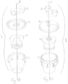
- Fig. 1A shows a nozzle assembly 1 in an assembled configuration.
- the nozzle assembly 1 comprises a input fitting 2, a cap 3, an insert 4, and a body 5.
- the insert 4 is coupled to the cap 3
- the cap 3 is coupled to the body 5 and the insert 4, with the insert 4 positioned within the body 5.
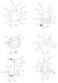
- Figs. 2A-2G show an input fitting 2.
- the input fitting 2 includes a first input port 6 and a second input port 7.
- the first input port 6 and the second input port 7 are radially offset from the central axis 8 of the nozzle assembly 1.
- the first input port 6 and the second input port 7 may be circular and are sized and shaped to couple to fluid conduits connected to fluid sources, for example as shown in Figs. 7A-7F .
- Input fitting 2 further includes a first output port 9.
- First output port 9 may be circular as shown in Figs. 2C and 2D .
- First input port 6 and first output port 9 are coaxial and fluidly connected to define a portion of a first flow path.
- the portion of the first flow path defined by the first input port 6 and the first output port 9 is generally straight so that a first liquid can flow straight through the input fitting, as indicated by the straight line arrow 201 of Fig. 2E .
- Input fitting 2 further includes a second output port 10.
- Second output port 10 may be elongated in shape with circular ends as shown in Figs. 2C and 2D .
- a first end 11 of the second output port 10 is aligned with second input port 7.
- a second end 12 of the second the output port 10 is not aligned with second input port 7, and as will be discussed in greater detail below is positioned so that when the input fitting 2 is coupled to the cap 3 as part of the nozzle assembly 1 the central axis 8 extends through the second end 12 of the second output port 10.
- the second input port 7 and the second output port 10 are connected to define a portion of a second flow path, along with the cap 3 as will be discussed below.
- the portion of the second flow path is serpentine in shape from the second input port 7, to the first end 11 of the second output port 10, to the second end 12 of the second output port 10.
- the portion of the second flow path allows for a second liquid to flow through the input fitting, as indicated by the S shaped arrow 202 of Fig. 2E .
- the input fitting 2 is formed as a single component, or as two or more components, for example a first component with the first input and output ports, and a second component with the second input port and the second output port.
- Cap 3 includes a top surface 13 that defines a portion of an outer surface of the nozzle assembly 1, and a bottom surface 14 that defines a portion of an inner surface of the nozzle assembly 1.
- Top surface 13 includes a first recess 15 and a second recess 16.
- First recess 15 is generally circular and is sized and shaped to receive and couple to the first output port 9 of the input fitting 2.
- the second recess 16 is elongated in shape with rounded ends and is sized and shaped to receive and couple to the second output port 10 of the input fitting 2.
- the second recess 16 extends from the center of the cap 3, which corresponds to the central axis 8 of the nozzle assembly 1, toward a perimeter of the cap 3.
- the first recess 15 include a first through hole 17 concentric with the first recess 15.
- the second recess 16 includes a second through hole 18 at the center of the cap 3. With the input fitting 2 coupled to the cap 3 a portion of the first flow path is defined from the first input port 6 through the first through hole 17, and a portion of the second flow path is defined from the second input port 7 through the second through hole 18.
- the surface of the second recess defines an inner surface of the second flow path.
- cap 3 further includes a bottom surface 14 surrounded by a flange 19. Extending downwardly from the bottom surface 14 is a coupling ring 20 in the center of the bottom surface 14. Coupling ring 20 surrounds the second through hole 18 and is shaped and sized to couple to the insert 4, as will be discussed in greater detail below.
- insert 4 includes an upper plate 21, a lower plate 22, and a conical portion 23.
- Upper plate 21 is generally circular with an outer edge 24 shaped and angled to form a flush seal against the inner surface 25 of the body 5.
- Upper plate 21 further includes a plurality of through holes 26.
- the through holes 26 may be positioned along a single circular pattern, which is around the central axis 8 of the nozzle assembly 1.
- the through holes 26 of the upper plate 21 include eight equally spaced through holes. However, other numbers and patterns of through holes 26 may be included.
- the through holes 26 have diameter in the range of 1.3 mm (0.05 inches) and 3.0 mm (0.12 inches), and preferably 2.0 mm (0.08 inches).
- lower plate 22 is generally circular with an outer edge 27 shaped and angled to form a flush seal against the inner surface 25 of the body 5.
- the outer edge 27 of lower plate 22 may be narrower at the bottom and wider at the top, as shown in Fig. 4E .
- Lower plate 22 further includes a plurality of through holes 28.
- the through holes 28 may be positioned in a double concentric circular pattern.
- the through holes 28 of the lower plate 22 include ten through holes in the inner circle and fifteen through holes in the outer circle each equally spaced in their respective circles.
- the outer through holes may have the same, a larger, or a smaller diameter than the inner through holes.
- the through holes 28 may have a diameter between 1.0 mm (0.04 inches) and 1.5 mm (0.06 inches), and preferably about 2.0 mm (0.08 inches). This arrangement of through holes 28 of the lower plate 22 causes substantially uniform flow in all radial directions of fluid exiting the lower plate 22, as will be discussed in greater detail below.
- the lower plate 22 may have through holes with other diameters and may have through holes with a plurality of different diameters, and/or a different number of through holes, and/or a different number of concentric circles, and/or a different pattern.
- the lower plate 22 has a smaller diameter than the upper plate 21 in order for the insert 4 to be positioned within the body 5 against the tapered inner surface 25 to form a seal.
- conical portion 23 include a conical outer surface 29 and a bottom surface 30.
- the conical outer surface 29 extends from the upper plate 21 to an interface with the bottom surface 30 and may be frustoconical in shape.
- the conical outer surface 29 may be concave so that the width of the cross-section of the outer surface increases from the upper plate 21 to the bottom surface 30 in a non-linear manner, with the rate of increase in the width increasing toward the bottom surface 30.
- the outer surface 29 of the conical portion 23 is concave in a cross-sectional plane parallel to the central axis and may be referred to as "bell shaped". This concave shape has the advantage of gradually decreasing the cross-section of the volume between the insert 4 and the body 5.
- the conical portion 23 may have a straight side wall profile or a convex sidewall profile.
- the bottom surface 30 may be flat and may be separated from and parallel to the lower plate 22.
- the gap 31 between the bottom surface 30 and the lower plate 22 may range from 2.5 mm (0.1 inches) to 13 mm (0.5 inches), and is preferably about 5.1 mm (0.2 inches).
- the bottom surface 30 overlaps the through holes 28 of the lower plate 22 when viewed from a plane perpendicular to the central axis 8.
- the insert 4 further defines a central lumen 32 extending from a coupling 33 at the top of the insert 4 above the upper plate 21, through the upper plate 21, through the conical portion 23, through the lower plate 22 and to an outlet end 34.
- the central lumen 32 is generally circular in profile.
- the central lumen 32 is open at the coupling 33.
- Coupling 33 is shaped and sized to couple with the coupling ring 20 of the cap 3 to form a watertight seal.
- the outlet end 34 at the bottom of the central lumen 33 defines a plurality of outlets 35.
- the outlets 35 may be rectangular in profile and are oriented to direct a fluid stream flowing into the central lumen 32 from the coupling 33 out in a radial pattern in an exit plane perpendicular to the central axis 8.
- the outlets 35 are square with sides between 1.0 mm (0.04 inches) and 2.5 mm (0.1 inches), and preferably 1.5 mm (0.06 inches).
- the exit plane is substantially parallel to the bottom of the lower plate 22 and as will be discussed below allows for the fluid flowing through the central lumen 32 to mix with the fluid flowing through the through holes 28 of the lower plate 22.
- Body 5 includes a top opening 36 and a bottom opening 37 on opposite ends of the inner surface 25. As shown, top opening 36 may be smaller than bottom opening 37 so that the inner surface 25 tapers from the top to the bottom of the body 5.
- the taper of the inner surface 25 may be a curved taper. In embodiments the taper may be straight.
- the taper of the inner surface 25 defines an axial position where the insert 4 will be positioned and form a seal.
- the diameters of the upper plate 21 and lower plate 22 correspond to the taper of the inner surface 25.
- the body further comprises an outer surface 38. At the top of the body 5, the outer surface 38 includes a flange 39 sized and shaped to form a seal with the flange 19 of the cap 3. When flange 39 and flange 19 couple and seal the interior of the body 5 and cap 3 define a watertight compartment with through holes 17 and 18 defining inlets and bottom opening 37 defining an outlet.
- Figs. 6A-6F show a nozzle assembly 1 including an input fitting 2, cap 3, insert 4, and body 5, as disclosed above.
- insert 4 is positioned in the body 5 so that upper plate 21 forms a seal with inner surface 25, and lower plate 22 forms a seal with inner surface 25.
- the taper of inner surface 25 at lower plate 22 prevents insert 4 from being positioned lower in body 5.
- the coupling 33 is located substantially in the plane of the top opening 36 of the body 5 so that when the cap 3 couples to the body 5 the coupling ring 20 couples to and forms a seal with coupling 33.
- the nozzle assembly 1 defines two flow paths, a first flow path and a second flow path.
- the first flow path begins at the first input port 6 of the input fitting 2 and flows parallel to the central axis 8 through the first output port 9, through the first through hole 17 of cap 3, and into an upper chamber 40 defined by the inner surface 25 of the body 5, the cap 3, and the upper plate 21 of the insert 4.
- the outer edge 24 of the upper plate 21 seals with the inner surface 25 of the body 5.
- the upper chamber 40 is a toroid in shape with the central lumen 32 in the void/hole of the toroid. When fluid enters the upper chamber 40 from the first input port 6 the fluid substantially occupies the entire volume of the upper chamber 40.
- the first middle chamber 41 is defined by the upper plate 22, the inner surface 25 of the body 5, and the conical outer surface 29. As shown in Figs. 6B and the cross-sections of Fig. 6D and 6E , the first middle chamber 41 is toroid in shape with the central lumen 32 in the void/hole of the toroid. As shown, the upper portion 42 of the first middle chamber 41 has a larger cross sectional area than the bottom portion 43 due to the wider inner surface 25 diameter and smaller conical portion 23 diameter at the upper portion 42 compared to the narrower inner surface 25 diameter and larger conical portion 23 diameter at the bottom portion 43 of the first middle chamber 41. As fluid passes through the first middle chamber 41 the velocity increases due to this reduction in cross-sectional area.
- the diameter of the inner surface 25 of the body 5 at the bottom of the conical portion 23 is larger than the diameter of the bottom of the conical portion 23 so that a ring gap 44 is defined between the two.
- the first flow path flows from the first middle chamber 41 through the ring gap 44 and into a second middle chamber 45.
- the width of the ring gap 44 may be between 0.04 inches and 0.1 inches, and preferably about 0.07 inches.
- the increased velocity in the lower portion 43 of the first middle chamber 41 further generates a uniform flow rate in all radial directions around the ring gap 44.
- the second middle chamber 45 is defined by the bottom surface 30, the ring gap 44, the stem 46, the lower plate 22 and the inner surface 25 of the body 5.
- the second middle chamber 45 is toroid in shape with the central lumen 32 in the void/hole of the toroid.
- the ring gap may be greater in diameter than the circular pattern of through holes 28. This larger diameter has the advantage of further causing entering from the ring gap to be directed toward the central axis 8 in order to reach the through holes 28 which causes a uniform flow in all radial directions through the through holes 28.
- the course of the first flow path causes a fluid entering the nozzle 1 at a position offset from the central axis 8, to be distributed around the central axis 8 and exit through the through holes 28 of the lower plate 22 with a substantially uniform flow rate in all radial directions around the central axis.
- the first flow path surrounds and is fluidly separated from the central lumen 32.
- the second flow path begins at the second input port 7 of the input fitting 2 and at the second input port 7 initially flows parallel to the central axis 8. From the second input port 7, the second flow path enters the second output port 10 and initially flows perpendicular to the central axis 8 and then flows coaxially with the central axis through the second through hole 18 of cap 3, as discussed above and shown by the curved arrow in Fig. 2E .
- this serpentine path allows for the first and second input ports 7 and 9 to be positioned at mirror-image locations offset from the central axis 8 at the top of the nozzle assembly 1, while allowing the fluid entering the second input port to reach the central axis 8 and flow through the central lumen 32.
- the second flow path After passing through the second through hole 18 the second flow path enters and flows through the central lumen 32 of the insert 4 while being encircled by and fluidly separated from the first flow path. The second flow path then flows out of the outlets 35 in a radial pattern perpendicular to the central axis 8 into the mixing chamber 47.
- the flow of a first fluid flowing through the first flow path mixes with a second fluid flowing through the second flow path. Due to the uniform flow rates in the radial direction of both the first flow path and the second flow path in the mixing chamber, the ratio of first fluid to second fluid in all radial directions in the mixing chamber 47 is uniform. Additionally, the vertical flow of the first fluid flow path and the horizontal flow of the second fluid flow path lead to uniform mixing of the fluids caused by the perpendicular collision of the streams. The resulting output of the post-mixed beverage is uniform in flow rate and mixing ratio in all radial directions.
- the first fluid flowing through the first flow path may be a base fluid comprising water, carbonated water, or a mixture thereof.
- the second fluid flowing through the second flow path may be a mixer fluid such as one or more flavoring syrups, an alcohol fluid, or a mixture thereof.
- the flow paths and input fluids are configured to result in a desired output carbonation, cup foam height, and output temperature.
- the components as disclosed above may be manufactured as one or more integral components.
- the cap 3 and input fitting 3 may be formed as one part.
- the components may be fitted together with adhesives, welding, threading, press fit, and combinations thereof.
- the components may formed for example by molding, additive manufacturing (e.g. 3D printing), and/or subtractive manufacturing (e.g. machining).
- the components may be made of plastic, metal, ceramic, and combinations thereof, and the components of the nozzle assembly 1 may be made of different or the same materials.
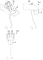
- Figs. 7A-7F show a post-mix beverage dispensing apparatus 701 including a dispensing nozzle assembly 1, as disclosed above.
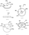
- Fig. 8A shows a nozzle assembly 801 not according to the invention, similar to the nozzle assembly of Fig. 1A .
- Figs. 8B and 8C show exploded views of the nozzle assembly 801 of Fig. 8A .
- the nozzle assembly 801 includes an input fitting 802 shown in more detail in Figs. 9A-9G , a cap 803 shown in more detail in Figs. 10A-10E , an insert 804 shown in more detail in Figs. 11A-11F , and a body 805 shown in more detail in Figs. 12A-12C .
- Figs. 9A-9G show an input fitting 802.
- the input fitting 802 includes a first input port 806 and a second input port 807.
- the first input port 806 and the second input port 807 are radially offset from the central axis 808 of the nozzle assembly 801.
- the first input port 806 and the second input port 807 may be circular and are sized and shaped to couple to fluid conduits connected to fluid sources.
- Input fitting 802 further includes a first output port 809.
- First output port 809 may be circular as shown in Figs. 9C and 9D .
- First input port 806 and first output port 809 are coaxial and fluidly connected to define a portion of a first flow path.
- the portion of the first flow path defined by the first input port 806 and the first output port 809 is generally straight so that a first liquid can flow straight through the input fitting, as indicated by the straight line arrow 901 of Fig. 9E .
- Input fitting 802 further includes a second output port 810.
- Second output port 810 may be elongated in shape with circular ends as shown in Figs. 9C and 9D .
- a first end 811 of the second output port 810 is aligned with second input port 807.
- a second end 812 of the second the output port 810 is not aligned with second input port 807, and as will be discussed in greater detail below is positioned so that when the input fitting 802 is coupled to the cap 803 as part of the nozzle assembly 801 the central axis 808 extends through the second end 812 of the second output port 810.
- the second input port 807 and the second output port 810 are connected to define a portion of a second flow path, along with the cap 803 as will be discussed below.
- the portion of the second flow path is serpentine in shape from the second input port 807, to the first end 811 of the second output port 810, to the second end 812 of the second output port 810.
- the input fitting 802 is formed as a single component, or as two or more components, for example a first component with the first input and output ports, and a second component with the second input port and the second output port.
- Cap 803 includes a top surface 813 that defines a portion of an outer surface of the nozzle assembly 801, and a bottom surface 814 that defines a portion of an inner surface of the nozzle assembly 801.
- Top surface 813 includes a first recess 815 and a second recess 816.
- First recess 815 is generally circular and is sized and shaped to receive and couple to the first output port 809 of the input fitting 802.
- the second recess 816 is elongated in shape with rounded ends and is sized and shaped to receive and couple to the second output port 810 of the input fitting 802.
- the second recess 816 extends from the center of the cap 803, which corresponds to the central axis 808 of the nozzle assembly 801, toward a perimeter of the cap 803.
- the first recess 815 include a first through hole 817 concentric with the first recess 815.
- the second recess 816 includes a second through hole 818 at the center of the cap 803.
- cap 803 further includes a bottom surface 814 surrounded by a flange 819. Extending downwardly from the bottom surface 814 is a coupling ring 820 in the center of the bottom surface 814. Coupling ring 820 surrounds the second through hole 818 and is shaped and sized to couple to the insert 804, as will be discussed in greater detail below.
- Cap 803 further comprises a outer coupling ring 1001 extending downwardly from flange 819. Outer coupling ring 1001 is circular and shaped and sized to be receiving within body 805. Outer coupling ring 1001 defines locking 1002 tracks which received locking tabs 1201 of the body 805 in order to couple the body to the cap.
- the locking tracks 1002 are L-shaped. To couple the body 805 to the cap 803 the outer coupling ring 1001 is inserted into the body 805 with the locking tabs 1201 positioned within the vertical portion of the L-shaped locking tracks 1002, the cap 803 is then rotated relative to the body 805 so that the locking tabs 1201 translate along the horizontal portion of the L-shaped locking in order to prevent vertical movement of the cap relative to the body.
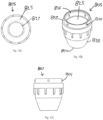
- insert 804 includes an upper plate 821, a lower core portion 822, and a plurality of fins 823.
- Upper plate 821 is generally circular with an outer edge 824 shaped and angled to form a flush seal against the inner surface 825 of the body 805.
- Upper plate 821 further includes a plurality of through holes 826. For clarity in the figures only a portion of the through holes 826 are indicated with reference numerals and lead lines. As shown in Fig. 11C the through holes 826 may be positioned along a single circular pattern, which is around the central axis 808 of the nozzle assembly 801.
- the through holes 826 of the upper plate 821 include eight equally spaced through holes. However, other numbers and patterns of through holes 826 may be included. In embodiments, the through holes 826 have diameter in the range of 0.05 inches and 0.12 inches, and preferably 0.08 inches.
- lower core portion 822 has a tapered upper portion, a cylindrical center portion, and a tapered lower portion.
- a plurality of vanes 823 extend radially from the lower core portion 822.
- the insert 804 includes 12 vanes, however inserts may include other numbers of vanes.
- the vanes 823 are generally trapezoidal in shape including an upper angle edge facing the upper plate 821, a lower angled edged facing away from the upper plate 821, and a straight edge 827 parallel to the center axis 808 and shaped and angled to contact the inner surface 825 of the body 805, as shown in Figs. 13B and 13E .
- the arrangement of vanes 823 causes substantially uniform flow in all radial directions of a mixed fluid passing through the vanes from upstream of the vanes from the first and second flow paths.
- the insert 804 further defines a central lumen 832 extending from a coupling 833 at the top of the insert 804 above the upper plate 821, through the upper plate 821, and to an outlet region 834, adjacent to the upper portion of the lower core portion 822.
- the central lumen 832 is generally circular in profile.
- the central lumen 832 is open at the coupling 833.
- Coupling 833 is shaped and sized to couple with the coupling ring 820 of the cap 803 to form a watertight seal.
- the outlet region 834 at the bottom of the central lumen 833 defines a plurality of outlets 835. As shown, the outlets 835 may be rectangular in profile and are oriented to direct a fluid stream flowing into the central lumen 832 from the coupling 833 out in a radial pattern in an exit plane perpendicular to the central axis 808.
- Body 805 includes a top opening 836 and a bottom opening 837 on opposite ends of the inner surface 825. As shown, top opening 836 may be smaller than bottom opening 837 so that the inner surface 825 tapers from the top to the bottom of the body 805.
- the taper of the inner surface 825 may be a curved taper. In embodiments the taper may be straight.
- the taper of the inner surface 825 defines an axial position where the insert 804 will be positioned and form a seal.
- the body further comprises an outer surface 838. At the top of the body 805, the outer surface 838 includes a flange 839 sized and shaped to form a seal with the flange 819 of the cap 803. When flange 839 and flange 819 couple and seal the interior of the body 805 and cap 803 define a watertight compartment with through holes 817 and 818 defining inlets and bottom opening 837 defining an outlet.
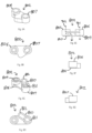
- Figs. 13A-13F shows various cross-sectional views of the nozzle assembly of Fig. 8A .
- the insert 804 comprising the plurality of vanes 823 defines internal radial flow paths with the body.
- the internal radial flow paths have wide top sections, narrower middle sections, and wide bottom sections due to the shape of the lower core portion 822.
- the lower core portion core of the insert, from which the vanes extend is wider in a middle portion than the top and bottom portions, as shown in Figs. 13D-13F .
- the nozzle assembly 801 defines a first flow path for a first beverage component from a first input port radially offset from a central vertical axis of the nozzle, into a chamber where the first fluid is dispersed radially around the central vertical axis, then through holes in a plate into a mixing chamber.
- a second flow path for a second beverage component is defined to flow from a second input port aligned with the central vertical axis and through a lumen into the mixing chamber. Similar to the nozzle assembly of Fig. 1A , a portion of the first flow path within the body is separate from and surrounds a portion of the second flow path within the body. In the mixing chamber the first and second beverage components initially mix.
- Figs. 14A-14F show a post-mix beverage dispensing apparatus 1400 including a dispensing nozzle 801 of Fig. 8A .
- a nozzle assembly 801 includes an input fitting 802, a cap 803, an insert 804, and a body 805, as disclosed above.
- insert 804 is positioned in the body 805 so that upper plate 821 forms a seal with inner surface 825, and vanes 823 contact inner surface 825.
- the taper of inner surface 825 at vanes 823 prevents insert 804 from being positioned lower in body 805.
- the coupling 833 is located substantially in the plane of the top opening 836 of the body 805 so that when the cap 803 couples to the body 805 the coupling ring 820 couples to and forms a seal with coupling 833.
- the nozzle assembly 801 defines two flow paths, a first flow path and a second flow path.
- the first flow path begins at the first input port 806 of the input fitting 802 and flows parallel to the central axis 808 through the first output port 809, through the first through hole 817 of cap 803, and into an upper chamber 840 defined by the inner surface 825 of the body 805, the cap 803, and the upper plate 821 of the insert 804.
- the outer edge 824 of the upper plate 821 seals with the inner surface 825 of the body 805.
- the upper chamber 840 is a toroid in shape with the central lumen 832 in the void/hole of the toroid. When fluid enters the upper chamber 840 from the first input port 806 the fluid substantially occupies the entire volume of the upper chamber 840.
- the middle chamber 841 is defined by the upper plate 822, the inner surface 825 of the body 805, the vanes 823 and the lower core portion 822.
- the middle chamber 841 is toroidal in shape with the central lumen 32 in the void/hole of the toroid.
- an upper portion of the middle chamber 841 has a larger cross sectional area than a bottom portion due to the tapering of the lower core portion 822. As fluid passes through the middle chamber 841 the velocity increases due to this reduction in cross-sectional area.
- the course of the first flow path causes a fluid entering the nozzle 801 at a position offset from the central axis 808, to be distributed around the central axis 808 and pass through the through holes 826 with a substantially uniform flow rate in all radial directions around the central axis.
- the second flow path begins at the second input port 807 of the input fitting 802 and at the second input port 807 initially flows parallel to the central axis 8. From the second input port 807, the second flow path enters the second output port 810 and initially flows perpendicular to the central axis 808 and then flows coaxially with the central axis through the second through hole 818 of cap 803, as discussed above and shown by the curved arrow in Fig. 9E . As noted above, this serpentine path allows for the first and second input ports 807 and 809 to be positioned at mirror-image locations offset from the central axis 808 at the top of the nozzle assembly 801, while allowing the fluid entering the second input port to reach the central axis 808 and flow through the central lumen 832.
- the second flow path After passing through the second through hole 818 the second flow path enters and flows through the central lumen 832 of the insert 804 while being encircled by and fluidly separated from the first flow path.
- the second flow path then flows out of the outlets 835 in a radial pattern perpendicular to the central axis 808 into the upper chamber 840.
- the flow of a first fluid flowing through the first flow path mixes with a second fluid flowing through the second flow path. Due to the uniform flow rates in the radial direction of both the first flow path and the second flow path in the upper chamber 840, the ratio of first fluid to second fluid in all radial directions in the upper chamber 840 is uniform. Additionally, the vertical flow of the first fluid flow path and the horizontal flow of the second fluid flow path lead to uniform mixing of the fluids caused by the perpendicular collision of the streams. The resulting output of the post-mixed beverage is uniform in flow rate and mixing ratio in all radial directions.
- the first fluid flowing through the first flow path may be a base fluid comprising water, carbonated water, or a mixture thereof.
- the second fluid flowing through the second flow path may be a mixer fluid such as one or more flavoring syrups, an alcohol fluid, or a mixture thereof.
- the flow paths and input fluids are configured to result in a desired output carbonation, cup foam height, and output temperature.
- the components as disclosed above may be manufactured as one or more integral components.
- the cap 803 and input fitting 803 may be formed as one part.
- the components may be fitted together with adhesives, welding, threading, press fit, and combinations thereof.
- the components may formed for example by molding, additive manufacturing (e.g. 3D printing), and/or subtractive manufacturing (e.g. machining).
- the components may be made of plastic, metal, ceramic, and combinations thereof, and the components of the nozzle assembly 801 may be made of different or the same materials.
Landscapes
- Devices For Dispensing Beverages (AREA)
- Apparatus For Making Beverages (AREA)
- Nozzles (AREA)
Claims (10)
- Buse de distribution de boisson post-mélange (1), comprenant :un corps (5) comprenant une ouverture de sommet (36), une ouverture de fond (37) opposée à l'ouverture de sommet (36), un axe vertical central (8) s'étendant entre l'ouverture de sommet (36) et l'ouverture de fond (37), et une surface intérieure (25) s'étendant entre l'ouverture de sommet (36) et l'ouverture de fond (37) et entourant l'axe vertical central (8) ;un premier orifice d'entrée (6) disposé au niveau de l'ouverture de sommet (36) et décalé radialement par rapport à l'axe vertical central (8) ; etun second orifice d'entrée (7) disposé au niveau de l'ouverture de sommet (36) ;dans laquelle un premier trajet d'écoulement pour un premier composant de boisson est défini pour s'écouler depuis le premier orifice d'entrée (6), à travers le corps (5), et hors de l'ouverture de fond (37),dans laquelle un second trajet d'écoulement pour un second composant de boisson est défini pour s'écouler depuis le second orifice d'entrée (7), à travers le corps (5), coïncidant avec l'axe central (8), et hors de l'ouverture de fond (37),dans laquelle une portion du premier trajet d'écoulement l'intérieur du corps (5) est séparée et entoure une portion du second trajet d'écoulement à l'intérieur du corps (5), etdans laquelle le premier trajet d'écoulement et le second trajet d'écoulement sont configurés de telle sorte que le premier composant de boisson et le second composant de boisson se mélangent avant de sortir de l'ouverture de fond (37),dans laquelle la buse de distribution de boisson post-mélange (1) comprend en outre un insert (4) à l'intérieur du corps (5),dans laquelle l'insert (4) comprend une portion conique (23), une plaque supérieure (21) positionnée entre la portion conique (23) et l'ouverture de sommet (36), et une plaque inférieure (22) positionnée entre la portion conique (23) et l'ouverture de fond (37),dans laquelle le premier trajet d'écoulement s'écoule depuis le premier orifice d'entrée (6) jusque dans une chambre supérieure (40),dans laquelle le premier trajet d'écoulement s'écoule depuis la chambre supérieure (40) jusqu'à une première chambre intermédiaire (41) définie par la surface intérieure (25), la plaque supérieure (21) et une surface conique (29) de la portion conique (23),dans laquelle le premier trajet d'écoulement s'écoule depuis la première chambre intermédiaire (41) jusqu'à une seconde chambre intermédiaire (45) définie par la surface intérieure (25), la plaque inférieure (22) et une surface de fond (30) de la portion conique (23),dans laquelle le premier trajet d'écoulement s'écoule depuis la seconde chambre intermédiaire (45) jusqu'à une chambre de mélange (47) définie par la surface intérieure (25), la plaque inférieure (22) et l'ouverture de fond (37),dans laquelle le corps conique définit une lumière (32) coïncidant avec l'axe central (8) et définissant une portion du second trajet d'écoulement, etdans laquelle le second trajet d'écoulement s'écoule depuis le second orifice d'entrée (7), à travers la lumière (32), et jusque dans la chambre de mélange (47),caractérisée en ce que le second orifice d'entrée (6) est décalé radialement par rapport à l'axe vertical central (8), et en ce que la chambre supérieure (40) est définie par la surface intérieure (25) et la plaque supérieure (21).
- Buse de distribution de boisson post-mélange (1) selon la revendication 1, dans laquelle la chambre supérieure (40) est sensiblement de forme toroïdale, et dans laquelle le second trajet d'écoulement s'écoule à travers un trou du tore de la chambre supérieure (40).
- Buse de distribution de boisson post-mélange (1) selon la revendication 1, dans laquelle la plaque supérieure (21) comprend une pluralité de premiers trous traversants (26) dans un motif circulaire autour de l'axe vertical central (8) et définissant une portion du premier trajet d'écoulement entre la chambre supérieure (40) et la première chambre médiane (41).
- Buse de distribution de boisson post-mélange (1) selon la revendication 1, dans laquelle la surface conique (29) de la portion conique (23) est de forme frustoconique, et dans laquelle une section transversale en aval du premier trajet d'écoulement dans la première chambre médiane (41) est plus petite qu'une section transversale en amont du premier trajet d'écoulement dans la première chambre médiane (41).
- Buse de distribution de boisson post-mélange (1) selon la revendication 4, dans laquelle un intervalle annulaire (44) est défini entre une portion inférieure de la portion conique (23) et la surface intérieure (25) du corps (5), et dans laquelle le premier trajet d'écoulement s'écoule depuis la première chambre médiane (41) à travers l'intervalle annulaire (44) jusqu'à la seconde chambre médiane (45).
- Buse de distribution de boisson post-mélange (1) selon la revendication 4, dans laquelle la surface conique (29) de la portion conique (23) est concave dans un plan de section transversale parallèle à l'axe central (8).
- Buse de distribution de boisson post-mélange (1) selon la revendication 1, dans laquelle la seconde chambre médiane (45) est sensiblement de forme toroïdale, et dans laquelle le second trajet d'écoulement s'écoule à travers un trou du tore de la seconde chambre médiane (45).
- Buse de distribution de boisson post-mélange (1) selon la revendication 1, dans laquelle la plaque inférieure (22) comprend une pluralité de seconds trous traversants (28) dans un motif circulaire autour de l'axe central (8) et définissant une portion du premier trajet d'écoulement depuis la seconde chambre médiane (45) jusqu'à la chambre de mélange (47).
- Buse de distribution de boisson post-mélange (1) selon la revendication 8, comprenant en outre une buse de sortie (34) à l'intérieur de la chambre de mélange (47), dans laquelle le second trajet d'écoulement s'écoule depuis la lumière (32) de la portion conique (23) jusqu'à la buse de sortie (34) et jusque dans la chambre de mélange (47) pour se mélanger avec le premier trajet d'écoulement.
- Buse de distribution de boisson post-mélange (1) selon la revendication 9, dans laquelle la buse de sortie (34) comprend une pluralité de sorties (35), dans laquelle la pluralité de sorties (35) dirigent le second trajet d'écoulement dans une pluralité de directions radialement par rapport à l'axe central (8).
Applications Claiming Priority (2)
| Application Number | Priority Date | Filing Date | Title |
|---|---|---|---|
| US201862774670P | 2018-12-03 | 2018-12-03 | |
| PCT/US2019/064295 WO2020117846A2 (fr) | 2018-12-03 | 2019-12-03 | Buse de post-mélange |
Publications (3)
| Publication Number | Publication Date |
|---|---|
| EP3877320A2 EP3877320A2 (fr) | 2021-09-15 |
| EP3877320A4 EP3877320A4 (fr) | 2022-08-10 |
| EP3877320B1 true EP3877320B1 (fr) | 2023-10-11 |
Family
ID=70972354
Family Applications (1)
| Application Number | Title | Priority Date | Filing Date |
|---|---|---|---|
| EP19893619.7A Active EP3877320B1 (fr) | 2018-12-03 | 2019-12-03 | Buse de post-mélange |
Country Status (6)
| Country | Link |
|---|---|
| US (1) | US11078066B2 (fr) |
| EP (1) | EP3877320B1 (fr) |
| AU (1) | AU2019391031B2 (fr) |
| BR (1) | BR112021010588A2 (fr) |
| CA (1) | CA3121254C (fr) |
| WO (1) | WO2020117846A2 (fr) |
Families Citing this family (16)
| Publication number | Priority date | Publication date | Assignee | Title |
|---|---|---|---|---|
| BR112021010588A2 (pt) * | 2018-12-03 | 2021-08-24 | Automatic Bar Controls, Inc. | Bico de dispensação de bebida pós-mistura |
| USD982382S1 (en) | 2020-03-20 | 2023-04-04 | Bedford Systems Llc | Nozzle for a beverage machine |
| US20210292152A1 (en) * | 2020-03-20 | 2021-09-23 | Bedford Systems Llc | Carbonated beverage nozzle for a beverage machine |
| US11760621B1 (en) * | 2022-03-28 | 2023-09-19 | Michael Curci | Post-mix beverage dispensing tap valve |
| US12096880B2 (en) | 2022-05-13 | 2024-09-24 | Sharkninja Operating Llc | Flavorant for beverage carbonation system |
| US11647860B1 (en) | 2022-05-13 | 2023-05-16 | Sharkninja Operating Llc | Flavored beverage carbonation system |
| US11751585B1 (en) | 2022-05-13 | 2023-09-12 | Sharkninja Operating Llc | Flavored beverage carbonation system |
| US12103840B2 (en) | 2022-11-17 | 2024-10-01 | Sharkninja Operating Llc | Ingredient container with sealing valve |
| US11745996B1 (en) | 2022-11-17 | 2023-09-05 | Sharkninja Operating Llc | Ingredient containers for use with beverage dispensers |
| US12084334B2 (en) | 2022-11-17 | 2024-09-10 | Sharkninja Operating Llc | Ingredient container |
| US11634314B1 (en) | 2022-11-17 | 2023-04-25 | Sharkninja Operating Llc | Dosing accuracy |
| US11738988B1 (en) | 2022-11-17 | 2023-08-29 | Sharkninja Operating Llc | Ingredient container valve control |
| US12116257B1 (en) | 2023-03-22 | 2024-10-15 | Sharkninja Operating Llc | Adapter for beverage dispenser |
| US11925287B1 (en) | 2023-03-22 | 2024-03-12 | Sharkninja Operating Llc | Additive container with inlet tube |
| US11871867B1 (en) | 2023-03-22 | 2024-01-16 | Sharkninja Operating Llc | Additive container with bottom cover |
| US12005408B1 (en) | 2023-04-14 | 2024-06-11 | Sharkninja Operating Llc | Mixing funnel |
Citations (1)
| Publication number | Priority date | Publication date | Assignee | Title |
|---|---|---|---|---|
| US5269442A (en) * | 1992-05-22 | 1993-12-14 | The Cornelius Company | Nozzle for a beverage dispensing valve |
Family Cites Families (18)
| Publication number | Priority date | Publication date | Assignee | Title |
|---|---|---|---|---|
| US3966091A (en) * | 1975-04-11 | 1976-06-29 | Eaton Corporation | Carbonated beverage dispenser having diffuser assembly |
| US4270673A (en) * | 1978-07-24 | 1981-06-02 | Alco Foodservice Equipment Company | Electric gravity dispensing valve |
| US4928854B1 (en) * | 1988-05-19 | 2000-04-04 | Mccann Eng & Mfg | Superflow diffuser and spout assembly |
| US4986447A (en) * | 1988-05-19 | 1991-01-22 | Mccann's Engineering And Manufacturing, Co. | Beverage distribution system |
| US5033651A (en) * | 1989-02-06 | 1991-07-23 | The Coca-Cola Company | Nozzle for postmix beverage dispenser |
| US5203474A (en) * | 1990-06-16 | 1993-04-20 | Alco Standard Corporation | Beverage dispensing nozzle |
| US5415326A (en) * | 1994-02-17 | 1995-05-16 | Lancer Corporation | Large volume beverage dispensing nozzle |
| US6345729B1 (en) * | 1998-08-03 | 2002-02-12 | Lancer Partnership, Ltd. | Multiple flavor beverage dispensing air-mix nozzle |
| US6047859A (en) * | 1998-08-03 | 2000-04-11 | Lancer Partnership, Ltd | Multiple flavor beverage dispensing air-mix nozzle |
| JP2000272698A (ja) * | 1999-03-19 | 2000-10-03 | Fuji Electric Co Ltd | シロップ飲料供給ノズル装置 |
| US6705489B2 (en) | 2001-05-30 | 2004-03-16 | Imi Cornelius Inc. | Ratio controlled post-mix valve |
| US20050072799A1 (en) * | 2003-01-03 | 2005-04-07 | Stratton Gus J. | Beverage dispensing apparatus including a whipper insert and method |
| US6871761B2 (en) * | 2003-06-03 | 2005-03-29 | David Fox | Post-mix beverage dispenser for frothed beverages |
| US7866509B2 (en) * | 2007-07-25 | 2011-01-11 | The Coca-Cola Company | Dispensing nozzle assembly |
| JP5709050B2 (ja) * | 2011-06-30 | 2015-04-30 | サントリーホールディングス株式会社 | 飲料調合ノズル |
| US10442671B2 (en) * | 2011-08-29 | 2019-10-15 | Automatic Bar Controls, Inc. | Nozzle with isolation porting |
| US9434594B2 (en) * | 2013-12-16 | 2016-09-06 | Panasonic Intellectual Property Management Co., Ltd. | Beverage dispenser |
| BR112021010588A2 (pt) * | 2018-12-03 | 2021-08-24 | Automatic Bar Controls, Inc. | Bico de dispensação de bebida pós-mistura |
-
2019
- 2019-12-03 BR BR112021010588-3A patent/BR112021010588A2/pt not_active Application Discontinuation
- 2019-12-03 WO PCT/US2019/064295 patent/WO2020117846A2/fr unknown
- 2019-12-03 US US16/702,428 patent/US11078066B2/en active Active
- 2019-12-03 EP EP19893619.7A patent/EP3877320B1/fr active Active
- 2019-12-03 CA CA3121254A patent/CA3121254C/fr active Active
- 2019-12-03 AU AU2019391031A patent/AU2019391031B2/en active Active
Patent Citations (1)
| Publication number | Priority date | Publication date | Assignee | Title |
|---|---|---|---|---|
| US5269442A (en) * | 1992-05-22 | 1993-12-14 | The Cornelius Company | Nozzle for a beverage dispensing valve |
Also Published As
| Publication number | Publication date |
|---|---|
| US20200180931A1 (en) | 2020-06-11 |
| US11078066B2 (en) | 2021-08-03 |
| CA3121254A1 (fr) | 2020-06-11 |
| BR112021010588A2 (pt) | 2021-08-24 |
| AU2019391031B2 (en) | 2024-11-21 |
| WO2020117846A3 (fr) | 2020-10-29 |
| EP3877320A4 (fr) | 2022-08-10 |
| CA3121254C (fr) | 2024-05-21 |
| AU2019391031A1 (en) | 2021-06-17 |
| EP3877320A2 (fr) | 2021-09-15 |
| WO2020117846A2 (fr) | 2020-06-11 |
Similar Documents
| Publication | Publication Date | Title |
|---|---|---|
| EP3877320B1 (fr) | Buse de post-mélange | |
| US11345583B2 (en) | Inserts and nozzle assemblies for beverage dispensers | |
| CA2943487C (fr) | Buse de distribution a debit eleve et a mousse reduite | |
| CA2536199C (fr) | Procede et dispositif relatifs a la buse d'un distributeur de boissons | |
| US5203474A (en) | Beverage dispensing nozzle | |
| EP3408215B1 (fr) | Buse avec arrangement de ports d'isolation | |
| CN112166085A (zh) | 用于后混合饮料分配的方法和装置 | |
| JP2011088678A (ja) | ポストミックス式自販機用分配ノズルによる異種流体の混合方法 | |
| EP4103507A1 (fr) | Buse de distribution de boisson | |
| CA3224044A1 (fr) | Buse de diffuseur pour distribution amelioree de carbonatation | |
| JP2004359257A (ja) | 飲料注出ノズル |
Legal Events
| Date | Code | Title | Description |
|---|---|---|---|
| STAA | Information on the status of an ep patent application or granted ep patent |
Free format text: STATUS: THE INTERNATIONAL PUBLICATION HAS BEEN MADE |
|
| STAA | Information on the status of an ep patent application or granted ep patent |
Free format text: STATUS: THE INTERNATIONAL PUBLICATION HAS BEEN MADE |
|
| PUAI | Public reference made under article 153(3) epc to a published international application that has entered the european phase |
Free format text: ORIGINAL CODE: 0009012 |
|
| STAA | Information on the status of an ep patent application or granted ep patent |
Free format text: STATUS: REQUEST FOR EXAMINATION WAS MADE |
|
| 17P | Request for examination filed |
Effective date: 20210611 |
|
| AK | Designated contracting states |
Kind code of ref document: A2 Designated state(s): AL AT BE BG CH CY CZ DE DK EE ES FI FR GB GR HR HU IE IS IT LI LT LU LV MC MK MT NL NO PL PT RO RS SE SI SK SM TR |
|
| DAV | Request for validation of the european patent (deleted) | ||
| DAX | Request for extension of the european patent (deleted) | ||
| REG | Reference to a national code |
Ref country code: HK Ref legal event code: DE Ref document number: 40061070 Country of ref document: HK |
|
| A4 | Supplementary search report drawn up and despatched |
Effective date: 20220712 |
|
| RIC1 | Information provided on ipc code assigned before grant |
Ipc: B67D 1/08 20060101ALI20220706BHEP Ipc: B67D 1/00 20060101AFI20220706BHEP |
|
| GRAP | Despatch of communication of intention to grant a patent |
Free format text: ORIGINAL CODE: EPIDOSNIGR1 |
|
| STAA | Information on the status of an ep patent application or granted ep patent |
Free format text: STATUS: GRANT OF PATENT IS INTENDED |
|
| INTG | Intention to grant announced |
Effective date: 20230424 |
|
| GRAS | Grant fee paid |
Free format text: ORIGINAL CODE: EPIDOSNIGR3 |
|
| GRAA | (expected) grant |
Free format text: ORIGINAL CODE: 0009210 |
|
| STAA | Information on the status of an ep patent application or granted ep patent |
Free format text: STATUS: THE PATENT HAS BEEN GRANTED |
|
| AK | Designated contracting states |
Kind code of ref document: B1 Designated state(s): AL AT BE BG CH CY CZ DE DK EE ES FI FR GB GR HR HU IE IS IT LI LT LU LV MC MK MT NL NO PL PT RO RS SE SI SK SM TR |
|
| REG | Reference to a national code |
Ref country code: GB Ref legal event code: FG4D |
|
| REG | Reference to a national code |
Ref country code: CH Ref legal event code: EP |
|
| REG | Reference to a national code |
Ref country code: DE Ref legal event code: R096 Ref document number: 602019039371 Country of ref document: DE |
|
| REG | Reference to a national code |
Ref country code: IE Ref legal event code: FG4D |
|
| PGFP | Annual fee paid to national office [announced via postgrant information from national office to epo] |
Ref country code: GB Payment date: 20231220 Year of fee payment: 5 |
|
| PGFP | Annual fee paid to national office [announced via postgrant information from national office to epo] |
Ref country code: FR Payment date: 20231222 Year of fee payment: 5 |
|
| REG | Reference to a national code |
Ref country code: LT Ref legal event code: MG9D |
|
| REG | Reference to a national code |
Ref country code: NL Ref legal event code: MP Effective date: 20231011 |
|
| REG | Reference to a national code |
Ref country code: AT Ref legal event code: MK05 Ref document number: 1620065 Country of ref document: AT Kind code of ref document: T Effective date: 20231011 |
|
| PG25 | Lapsed in a contracting state [announced via postgrant information from national office to epo] |
Ref country code: NL Free format text: LAPSE BECAUSE OF FAILURE TO SUBMIT A TRANSLATION OF THE DESCRIPTION OR TO PAY THE FEE WITHIN THE PRESCRIBED TIME-LIMIT Effective date: 20231011 |
|
| PG25 | Lapsed in a contracting state [announced via postgrant information from national office to epo] |
Ref country code: GR Free format text: LAPSE BECAUSE OF FAILURE TO SUBMIT A TRANSLATION OF THE DESCRIPTION OR TO PAY THE FEE WITHIN THE PRESCRIBED TIME-LIMIT Effective date: 20240112 |
|
| PG25 | Lapsed in a contracting state [announced via postgrant information from national office to epo] |
Ref country code: IS Free format text: LAPSE BECAUSE OF FAILURE TO SUBMIT A TRANSLATION OF THE DESCRIPTION OR TO PAY THE FEE WITHIN THE PRESCRIBED TIME-LIMIT Effective date: 20240211 |
|
| PG25 | Lapsed in a contracting state [announced via postgrant information from national office to epo] |
Ref country code: LT Free format text: LAPSE BECAUSE OF FAILURE TO SUBMIT A TRANSLATION OF THE DESCRIPTION OR TO PAY THE FEE WITHIN THE PRESCRIBED TIME-LIMIT Effective date: 20231011 |
|
| PG25 | Lapsed in a contracting state [announced via postgrant information from national office to epo] |
Ref country code: AT Free format text: LAPSE BECAUSE OF FAILURE TO SUBMIT A TRANSLATION OF THE DESCRIPTION OR TO PAY THE FEE WITHIN THE PRESCRIBED TIME-LIMIT Effective date: 20231011 |
|
| PG25 | Lapsed in a contracting state [announced via postgrant information from national office to epo] |
Ref country code: ES Free format text: LAPSE BECAUSE OF FAILURE TO SUBMIT A TRANSLATION OF THE DESCRIPTION OR TO PAY THE FEE WITHIN THE PRESCRIBED TIME-LIMIT Effective date: 20231011 |
|
| PG25 | Lapsed in a contracting state [announced via postgrant information from national office to epo] |
Ref country code: LT Free format text: LAPSE BECAUSE OF FAILURE TO SUBMIT A TRANSLATION OF THE DESCRIPTION OR TO PAY THE FEE WITHIN THE PRESCRIBED TIME-LIMIT Effective date: 20231011 Ref country code: IS Free format text: LAPSE BECAUSE OF FAILURE TO SUBMIT A TRANSLATION OF THE DESCRIPTION OR TO PAY THE FEE WITHIN THE PRESCRIBED TIME-LIMIT Effective date: 20240211 Ref country code: GR Free format text: LAPSE BECAUSE OF FAILURE TO SUBMIT A TRANSLATION OF THE DESCRIPTION OR TO PAY THE FEE WITHIN THE PRESCRIBED TIME-LIMIT Effective date: 20240112 Ref country code: ES Free format text: LAPSE BECAUSE OF FAILURE TO SUBMIT A TRANSLATION OF THE DESCRIPTION OR TO PAY THE FEE WITHIN THE PRESCRIBED TIME-LIMIT Effective date: 20231011 Ref country code: BG Free format text: LAPSE BECAUSE OF FAILURE TO SUBMIT A TRANSLATION OF THE DESCRIPTION OR TO PAY THE FEE WITHIN THE PRESCRIBED TIME-LIMIT Effective date: 20240111 Ref country code: AT Free format text: LAPSE BECAUSE OF FAILURE TO SUBMIT A TRANSLATION OF THE DESCRIPTION OR TO PAY THE FEE WITHIN THE PRESCRIBED TIME-LIMIT Effective date: 20231011 Ref country code: PT Free format text: LAPSE BECAUSE OF FAILURE TO SUBMIT A TRANSLATION OF THE DESCRIPTION OR TO PAY THE FEE WITHIN THE PRESCRIBED TIME-LIMIT Effective date: 20240212 |
|
| PGFP | Annual fee paid to national office [announced via postgrant information from national office to epo] |
Ref country code: DE Payment date: 20240227 Year of fee payment: 5 |
|
| PG25 | Lapsed in a contracting state [announced via postgrant information from national office to epo] |
Ref country code: SE Free format text: LAPSE BECAUSE OF FAILURE TO SUBMIT A TRANSLATION OF THE DESCRIPTION OR TO PAY THE FEE WITHIN THE PRESCRIBED TIME-LIMIT Effective date: 20231011 Ref country code: RS Free format text: LAPSE BECAUSE OF FAILURE TO SUBMIT A TRANSLATION OF THE DESCRIPTION OR TO PAY THE FEE WITHIN THE PRESCRIBED TIME-LIMIT Effective date: 20231011 Ref country code: PL Free format text: LAPSE BECAUSE OF FAILURE TO SUBMIT A TRANSLATION OF THE DESCRIPTION OR TO PAY THE FEE WITHIN THE PRESCRIBED TIME-LIMIT Effective date: 20231011 Ref country code: NO Free format text: LAPSE BECAUSE OF FAILURE TO SUBMIT A TRANSLATION OF THE DESCRIPTION OR TO PAY THE FEE WITHIN THE PRESCRIBED TIME-LIMIT Effective date: 20240111 Ref country code: LV Free format text: LAPSE BECAUSE OF FAILURE TO SUBMIT A TRANSLATION OF THE DESCRIPTION OR TO PAY THE FEE WITHIN THE PRESCRIBED TIME-LIMIT Effective date: 20231011 Ref country code: HR Free format text: LAPSE BECAUSE OF FAILURE TO SUBMIT A TRANSLATION OF THE DESCRIPTION OR TO PAY THE FEE WITHIN THE PRESCRIBED TIME-LIMIT Effective date: 20231011 |
|
| PGFP | Annual fee paid to national office [announced via postgrant information from national office to epo] |
Ref country code: IT Payment date: 20240130 Year of fee payment: 5 |
|
| PG25 | Lapsed in a contracting state [announced via postgrant information from national office to epo] |
Ref country code: DK Free format text: LAPSE BECAUSE OF FAILURE TO SUBMIT A TRANSLATION OF THE DESCRIPTION OR TO PAY THE FEE WITHIN THE PRESCRIBED TIME-LIMIT Effective date: 20231011 |
|
| REG | Reference to a national code |
Ref country code: DE Ref legal event code: R097 Ref document number: 602019039371 Country of ref document: DE |
|
| PG25 | Lapsed in a contracting state [announced via postgrant information from national office to epo] |
Ref country code: CZ Free format text: LAPSE BECAUSE OF FAILURE TO SUBMIT A TRANSLATION OF THE DESCRIPTION OR TO PAY THE FEE WITHIN THE PRESCRIBED TIME-LIMIT Effective date: 20231011 |
|
| PG25 | Lapsed in a contracting state [announced via postgrant information from national office to epo] |
Ref country code: SK Free format text: LAPSE BECAUSE OF FAILURE TO SUBMIT A TRANSLATION OF THE DESCRIPTION OR TO PAY THE FEE WITHIN THE PRESCRIBED TIME-LIMIT Effective date: 20231011 |
|
| PG25 | Lapsed in a contracting state [announced via postgrant information from national office to epo] |
Ref country code: SM Free format text: LAPSE BECAUSE OF FAILURE TO SUBMIT A TRANSLATION OF THE DESCRIPTION OR TO PAY THE FEE WITHIN THE PRESCRIBED TIME-LIMIT Effective date: 20231011 Ref country code: SK Free format text: LAPSE BECAUSE OF FAILURE TO SUBMIT A TRANSLATION OF THE DESCRIPTION OR TO PAY THE FEE WITHIN THE PRESCRIBED TIME-LIMIT Effective date: 20231011 Ref country code: RO Free format text: LAPSE BECAUSE OF FAILURE TO SUBMIT A TRANSLATION OF THE DESCRIPTION OR TO PAY THE FEE WITHIN THE PRESCRIBED TIME-LIMIT Effective date: 20231011 Ref country code: EE Free format text: LAPSE BECAUSE OF FAILURE TO SUBMIT A TRANSLATION OF THE DESCRIPTION OR TO PAY THE FEE WITHIN THE PRESCRIBED TIME-LIMIT Effective date: 20231011 Ref country code: DK Free format text: LAPSE BECAUSE OF FAILURE TO SUBMIT A TRANSLATION OF THE DESCRIPTION OR TO PAY THE FEE WITHIN THE PRESCRIBED TIME-LIMIT Effective date: 20231011 Ref country code: CZ Free format text: LAPSE BECAUSE OF FAILURE TO SUBMIT A TRANSLATION OF THE DESCRIPTION OR TO PAY THE FEE WITHIN THE PRESCRIBED TIME-LIMIT Effective date: 20231011 |
|
| REG | Reference to a national code |
Ref country code: CH Ref legal event code: PL |
|
| PLBE | No opposition filed within time limit |
Free format text: ORIGINAL CODE: 0009261 |
|
| STAA | Information on the status of an ep patent application or granted ep patent |
Free format text: STATUS: NO OPPOSITION FILED WITHIN TIME LIMIT |
|
| PG25 | Lapsed in a contracting state [announced via postgrant information from national office to epo] |
Ref country code: LU Free format text: LAPSE BECAUSE OF NON-PAYMENT OF DUE FEES Effective date: 20231203 |
|
| PG25 | Lapsed in a contracting state [announced via postgrant information from national office to epo] |
Ref country code: MC Free format text: LAPSE BECAUSE OF FAILURE TO SUBMIT A TRANSLATION OF THE DESCRIPTION OR TO PAY THE FEE WITHIN THE PRESCRIBED TIME-LIMIT Effective date: 20231011 |
|
| REG | Reference to a national code |
Ref country code: BE Ref legal event code: MM Effective date: 20231231 |
|
| PG25 | Lapsed in a contracting state [announced via postgrant information from national office to epo] |
Ref country code: MC Free format text: LAPSE BECAUSE OF FAILURE TO SUBMIT A TRANSLATION OF THE DESCRIPTION OR TO PAY THE FEE WITHIN THE PRESCRIBED TIME-LIMIT Effective date: 20231011 Ref country code: LU Free format text: LAPSE BECAUSE OF NON-PAYMENT OF DUE FEES Effective date: 20231203 |
|
| 26N | No opposition filed |
Effective date: 20240712 |
|
| REG | Reference to a national code |
Ref country code: IE Ref legal event code: MM4A |
|
| PG25 | Lapsed in a contracting state [announced via postgrant information from national office to epo] |
Ref country code: IE Free format text: LAPSE BECAUSE OF NON-PAYMENT OF DUE FEES Effective date: 20231203 |
|
| PG25 | Lapsed in a contracting state [announced via postgrant information from national office to epo] |
Ref country code: BE Free format text: LAPSE BECAUSE OF NON-PAYMENT OF DUE FEES Effective date: 20231231 |
|
| PG25 | Lapsed in a contracting state [announced via postgrant information from national office to epo] |
Ref country code: CH Free format text: LAPSE BECAUSE OF NON-PAYMENT OF DUE FEES Effective date: 20231231 |
|
| PG25 | Lapsed in a contracting state [announced via postgrant information from national office to epo] |
Ref country code: SI Free format text: LAPSE BECAUSE OF FAILURE TO SUBMIT A TRANSLATION OF THE DESCRIPTION OR TO PAY THE FEE WITHIN THE PRESCRIBED TIME-LIMIT Effective date: 20231011 |
|
| PG25 | Lapsed in a contracting state [announced via postgrant information from national office to epo] |
Ref country code: SI Free format text: LAPSE BECAUSE OF FAILURE TO SUBMIT A TRANSLATION OF THE DESCRIPTION OR TO PAY THE FEE WITHIN THE PRESCRIBED TIME-LIMIT Effective date: 20231011 Ref country code: IE Free format text: LAPSE BECAUSE OF NON-PAYMENT OF DUE FEES Effective date: 20231203 Ref country code: CH Free format text: LAPSE BECAUSE OF NON-PAYMENT OF DUE FEES Effective date: 20231231 Ref country code: BE Free format text: LAPSE BECAUSE OF NON-PAYMENT OF DUE FEES Effective date: 20231231 |