EP3877304B1 - Apparatus for metering bulk material - Google Patents
Apparatus for metering bulk material Download PDFInfo
- Publication number
- EP3877304B1 EP3877304B1 EP19808989.8A EP19808989A EP3877304B1 EP 3877304 B1 EP3877304 B1 EP 3877304B1 EP 19808989 A EP19808989 A EP 19808989A EP 3877304 B1 EP3877304 B1 EP 3877304B1
- Authority
- EP
- European Patent Office
- Prior art keywords
- bulk material
- screw
- conveying
- metering
- materials according
- Prior art date
- Legal status (The legal status is an assumption and is not a legal conclusion. Google has not performed a legal analysis and makes no representation as to the accuracy of the status listed.)
- Active
Links
- 239000013590 bulk material Substances 0.000 title claims description 96
- 239000000463 material Substances 0.000 claims description 23
- 230000008901 benefit Effects 0.000 description 11
- 238000009826 distribution Methods 0.000 description 7
- 238000004519 manufacturing process Methods 0.000 description 6
- 239000007787 solid Substances 0.000 description 6
- 239000000126 substance Substances 0.000 description 6
- 241000237858 Gastropoda Species 0.000 description 5
- 230000004913 activation Effects 0.000 description 5
- 238000000034 method Methods 0.000 description 5
- 230000010349 pulsation Effects 0.000 description 5
- 239000008187 granular material Substances 0.000 description 4
- 239000000843 powder Substances 0.000 description 4
- 239000000383 hazardous chemical Substances 0.000 description 3
- 206010052128 Glare Diseases 0.000 description 2
- 239000008186 active pharmaceutical agent Substances 0.000 description 2
- 230000007423 decrease Effects 0.000 description 2
- 230000009969 flowable effect Effects 0.000 description 2
- 230000033001 locomotion Effects 0.000 description 2
- 238000003860 storage Methods 0.000 description 2
- 241000273930 Brevoortia tyrannus Species 0.000 description 1
- 241001255830 Thema Species 0.000 description 1
- 239000000443 aerosol Substances 0.000 description 1
- TZCXTZWJZNENPQ-UHFFFAOYSA-L barium sulfate Chemical compound [Ba+2].[O-]S([O-])(=O)=O TZCXTZWJZNENPQ-UHFFFAOYSA-L 0.000 description 1
- 238000010923 batch production Methods 0.000 description 1
- 238000004140 cleaning Methods 0.000 description 1
- 238000010924 continuous production Methods 0.000 description 1
- 238000011161 development Methods 0.000 description 1
- 230000018109 developmental process Effects 0.000 description 1
- 239000003814 drug Substances 0.000 description 1
- 229940079593 drug Drugs 0.000 description 1
- 239000012847 fine chemical Substances 0.000 description 1
- 230000005484 gravity Effects 0.000 description 1
- 238000009413 insulation Methods 0.000 description 1
- 238000002955 isolation Methods 0.000 description 1
- 239000002086 nanomaterial Substances 0.000 description 1
- 239000002245 particle Substances 0.000 description 1
- 230000000149 penetrating effect Effects 0.000 description 1
- 230000000737 periodic effect Effects 0.000 description 1
- 239000002574 poison Substances 0.000 description 1
- 231100000614 poison Toxicity 0.000 description 1
- 230000000750 progressive effect Effects 0.000 description 1
- 238000000275 quality assurance Methods 0.000 description 1
- 238000000926 separation method Methods 0.000 description 1
- 210000002023 somite Anatomy 0.000 description 1
- 230000000007 visual effect Effects 0.000 description 1
Images


Classifications
-
- B—PERFORMING OPERATIONS; TRANSPORTING
- B65—CONVEYING; PACKING; STORING; HANDLING THIN OR FILAMENTARY MATERIAL
- B65G—TRANSPORT OR STORAGE DEVICES, e.g. CONVEYORS FOR LOADING OR TIPPING, SHOP CONVEYOR SYSTEMS OR PNEUMATIC TUBE CONVEYORS
- B65G33/00—Screw or rotary spiral conveyors
- B65G33/08—Screw or rotary spiral conveyors for fluent solid materials
- B65G33/14—Screw or rotary spiral conveyors for fluent solid materials comprising a screw or screws enclosed in a tubular housing
- B65G33/18—Screw or rotary spiral conveyors for fluent solid materials comprising a screw or screws enclosed in a tubular housing with multiple screws in parallel arrangements, e.g. concentric
-
- G—PHYSICS
- G01—MEASURING; TESTING
- G01F—MEASURING VOLUME, VOLUME FLOW, MASS FLOW OR LIQUID LEVEL; METERING BY VOLUME
- G01F11/00—Apparatus requiring external operation adapted at each repeated and identical operation to measure and separate a predetermined volume of fluid or fluent solid material from a supply or container, without regard to weight, and to deliver it
- G01F11/10—Apparatus requiring external operation adapted at each repeated and identical operation to measure and separate a predetermined volume of fluid or fluent solid material from a supply or container, without regard to weight, and to deliver it with measuring chambers moved during operation
- G01F11/12—Apparatus requiring external operation adapted at each repeated and identical operation to measure and separate a predetermined volume of fluid or fluent solid material from a supply or container, without regard to weight, and to deliver it with measuring chambers moved during operation of the valve type, i.e. the separating being effected by fluid-tight or powder-tight movements
- G01F11/20—Apparatus requiring external operation adapted at each repeated and identical operation to measure and separate a predetermined volume of fluid or fluent solid material from a supply or container, without regard to weight, and to deliver it with measuring chambers moved during operation of the valve type, i.e. the separating being effected by fluid-tight or powder-tight movements wherein the measuring chamber rotates or oscillates
- G01F11/24—Apparatus requiring external operation adapted at each repeated and identical operation to measure and separate a predetermined volume of fluid or fluent solid material from a supply or container, without regard to weight, and to deliver it with measuring chambers moved during operation of the valve type, i.e. the separating being effected by fluid-tight or powder-tight movements wherein the measuring chamber rotates or oscillates for fluent solid material
Definitions
- the invention relates to a device for dosing bulk materials according to the preamble of claim 1, in particular a dosing device for solids, essentially consisting of product storage and continuous product conveyance, namely a material-friendly, high-precision powder dosing device for demanding applications, e.g. for the pharmaceutical industry, special chemicals.
- the paver includes two augers and baffles located above the augers.
- the guide plates which are called bulk material screens in the present application, cover the screws in the longitudinal direction and not in the transverse direction. They also do not extend over the entire width of the respective screw conveyor.
- a dosing device of an agricultural distribution machine contains several screw conveyors and also guide plates, i.e. bulk material screens, which do not cover the screw conveyors, but are arranged perpendicular to the longitudinal axis of the screw conveyors and transverse to the conveying direction.
- EA CHOICE US2800252 EA CHOICE US3151782, GEA WO2013182869, Hess US3212624, Kardux US4945957, KTron US20070170209A1, Schenck DE102007055566B4, Schenck DE102010009753B4, Schenck EP1220804B1, Schenck EP1401747B1, Schenck EP1954610B1, Vibra Screw US5154326, VibraScrew US5937996 .
- the invention achieves the following advantages, among others: Advantage a: The residence time distribution of the product volume in the feeder is reduced.
- section A-A The mass flow (section A-A) is made possible by the asymmetrical screw trough (4), the bulk material screens (10), the three screw conveyors (6), and the vibration of this entire structure: vibration drive(s) (7)
- Vibration drives are all available machines that generate vibrations or impulses, such as magnetic exciters, knockers, ball vibrators, unbalance motors or directional exciters.
- screw types / modular structure three screws, 2 screws, 1 screw, 2-, 3- and 4-flight screws, Concave screws, spiral screws, intermeshing screws, self-cleaning screws, co-rotating screws, counter-rotating screws.
- Second is: first-in-first-out / mass flow / low residence time distribution
- the mass flow here is synonymous with first-in-first-out and is synonymous with low residence time distribution.
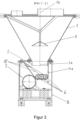
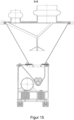
- the drawing shows a dosing device as it corresponds to the invention with the conical bulk material template (1), which sits on a housing (8) (not mandatory), the drive (5) and the screw tube (9). Other components are covered by the housing (8).
- the lines from A to A and from B to B define the visual axes of the figures 1 and 2 .
- the screens (10) form three staggered levels with the asymmetrical trough (4) (see also Figures 3 , 5 , 6 , 7 ), which gradually release the screw conveyors (6) in the direction of production (11) for the bulk material flowing thereon.
- the screw conveyors (6) are set in rotation by a drive with a gear or multiple drives (5).
- the screw conveyors (6) convey the bulk material out of the dosing device through the screw tube (9).
- the bulk material discharge plate (3) releases an annular gap for the bulk material.
- the bulk material relief plate prevents the bulk material from being compressed and further contributes to the activation of the bulk material and allows the mass flow in the bulk material receiver (1).
- the activation is generated by the vibration drive (7).
- the resulting movement activates the bulk material ( Principle: micro throw / see manual dosing, Gerhard Vetter, publisher: Vulkan Verlag Dec 2001, 2001, ISBN 10: 3802721993 / ISBN 13: 9783802721991 ).
- the outlet from the product receiver (2) is designed asymmetrically. See also figure 1 and the distance between the axes (1a) and (1b).
- the asymmetry aids the flow of bridging bulk materials and is an important part of the invention.
- a bulk product bridge is easiest to set up when the opposing supports on which the bridge ends rest are symmetrical. Due to the symmetry, the load of the upper part of the bulk material can be supported on the bottom layer of the bulk material, which is at the height of the supports. Due to the symmetry, the load is distributed evenly and the bulk material bridge can solidify. With asymmetrical supports, it is not possible to distribute the load evenly. As a result, the bulk material bridge that is being built up collapses again.
- the screw conveyors (6) here are each 2-flight concave screws meshing with one another.
- 4- and 3-flight intermeshing concave worms (not prior art) and spiral worms (prior art) are used.
- the 4- and 3-flight, intermeshing concave screws have several bulk material ejection flanks per revolution. As a result, an advantageous reduction in pulsation compared to the prior art can be achieved at low speeds.
- FIG. 5 - 7 is the area in the asymmetric screw trough (4).
- the bulk material screen (10) partially covers the augers (6).
- the screws (6) are gradually released, so that bulk material (17) is transported by the screws (6) in the direction of production (11).
- This detail is an essential part of the invention. Due to the geometry, the number of screws (6) and the screens, a mass flow is achieved in the area of the asymmetric screw trough (4); cf.
- FIG. 5 In the cone-shaped bulk material receiver, the bulk material level decreases during the dosing process, in principle as shown by lines (13) and (14). The almost parallel course of the two lines (13), (14) is characteristic of the mass flow. Lines (13), (14) are examples of the mass flow principle described. According to this principle, the bulk material flows in every point of the dosing device; from highest to lowest point, snails (6).
- the conical bulk material template is filled with the bulk material (15) in normal dosing operation. There is a free volume (16) below the bulk material discharge plate (3).
- a snail (6) is covered in this area by the built-in bulk material screen (10). As a result, the screw (6) is not filled with the bulk material (17) at this point.
- the built-in bulk material screen (10) covers two screws (6) in this area. As a result, the screws (6) are not filled with the bulk material (17) at this point.
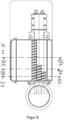
- the screw tube is designed differently.
- the augers are not flush with the pipe but are retracted. This results in a small storage area.
- the product-specific distance "X" between the screw 6 and the screw tube 9 results in an advantageous reduction in pulsation.
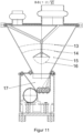
- Figures 9 to 12 show an alternative embodiment according to the invention with fixtures in the trough on the steep trough side.
- the device is built mirror-symmetrically, taking into account the function of the individual components.
- the screens are not provided on the sloping wall, but on the vertical wall.
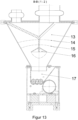
- Figures 13 to 14 Fig. 12 show another alternative embodiment according to the invention, wherein the method part is mirrored.
- the device is built mirror-symmetrically, taking into account the function of the individual components.
- the vertical wall of the screw trough is swapped with the sloping wall.
- FIGS 15 to 19 show further alternative embodiments according to the invention, here with various screw variations.
- the snails in the drawings "looking in front of the head", no longer lie as in figure 3 on an imaginary horizontal line, but are arranged, for example, in a sloping / tilted line ( Figures 16 to 19 ) or they are eg arranged in a V, in other words, the middle of three snails is offset downwards.
Description
Die Erfindung betrifft eine Vorrichtung zum Dosieren von Schüttgütern nach dem Oberbegriff von Anspruch 1, insbesondere ein Dosiergerät für Feststoffe, im Wesentlichen bestehend aus Produktvorlage und kontinuierlicher Produktförderung, nämlich einen materialschonenden, hochpräzisen Pulverdosierer für anspruchsvolle Anwendungen z.B. für die pharmazeutische Industrie, Spezialchemie.The invention relates to a device for dosing bulk materials according to the preamble of
Das Feststoffdosiergerät ist vorrangig für Pulver, Materialien, wie unter (a) definiert. Alternative Materialien (b) sind nicht auszuschließen (im Folgenden "Produkt" genannt):
- a. Beispiele für Pulver:
- o Granulate gemäß der pharmazeutischen Industrie
- o Stäube
- o Aerosole
- o Nanomaterialien
- o Gifte, Wirkstoffe, Feinchemikalien, APIs
- b. Andere Materialien (Pulver, Granulate gemäß allg. Chemie und Industrie) sind nicht ausgeschlossen.
- a. Examples of powder:
- o Granules according to the pharmaceutical industry
- o dusts
- o Aerosols
- o Nanomaterials
- o Poisons, Drugs, Fine Chemicals, APIs
- b. Other materials (powder, granules according to general chemistry and industry) are not excluded.
Die Erfindung steht im direkten Zusammenhang mit folgenden Trends der chemischen Industrien.
- (1) Pharmazeutische Industrie:
Ein Trend in der Industrie ist die Umstellung von Batch / Chargen-Produktion auf kontinuierliche Produktion. Aufgrund der branchenüblichen Vorgaben zur Rückverfolgbarkeit und Genauigkeit ist eine neue Dosiertechnik gefordert. - (2) Sonstige Industrie:
Auch in der Lebensmittelindustrie werden Stoffe verarbeitet, die in hoher Konzentration eine Gefahr darstellen. ATEX ist ebenfalls ein Thema in dieser Industrie. Daher gibt es auch in dieser Branche Anfragen zu staubdichten Dosierern. - (3) Spezialchemie / Gefahrstoffe:
Die Arbeitssicherheit bei der Verarbeitung von Gefahrstoffen kann mit vorhandener Dosiertechnik oft nur durch den Einsatz kostspieliger Isolation der Dosiergeräte gewährleistet werden. Eine Anforderung in dieser Industrie sind staubdichte Dosiergeräte, die keine Isolatoren benötigen (OEB).
- (1) Pharmaceutical industry:
A trend in the industry is the shift from batch/batch production to continuous production. A new dosing technology is required due to the standard industry specifications for traceability and accuracy. - (2) Other industry:
Substances that pose a risk in high concentrations are also processed in the food industry. ATEX is also an issue in this industry. Therefore, there are also inquiries about dust-tight metering devices in this industry. - (3) Specialty Chemicals / Hazardous Substances:
Occupational safety when processing hazardous substances can often only be guaranteed with existing dosing technology by using expensive insulation of the dosing devices. A requirement in this industry is dust-tight dispensers that do not require isolators (OEB).
-
1) Bislang verfügbare Feststoffdosierer lösen folgende Problemstellungen nur unzureichend:
- a. Verweilzeitverteilung des im Dosierer befindlichen Produktvolumens
- b. Mechanische Beanspruchung des Produkts im Schneckendosierern zu hoch, bzw. agglomeratfreie Dosierung nicht möglich
- c. Gleichmäßiger Produktaustrag bei geringen Dosierleistungen
- d. Großer Verstellbereich der Dosierleistung
- e. Das Dosieren von unterschiedlichen Produkten mit einer stark unterschiedlichen Fließeigenschaften in einem Dosierer Produkteigenschaften von fluidisierend bis stark kohäsiven / allgemein nicht fließfähigen Produkten
- f. Dosierer, der einen staubfreien Betrieb ermöglicht und damit die Voraussetzung zu einer OEB Zertifizierung erfüllt
- a. Residence time distribution of the product volume in the feeder
- b. Mechanical stress on the product in the screw feeder is too high, or agglomerate-free dosing is not possible
- c. Uniform product discharge with low dosing rates
- i.e. Large adjustment range of the dosing capacity
- e. The dosing of different products with widely differing flow properties in one doser Product properties from fluidizing to highly cohesive / generally non-flowable products
- f. dosing device that enables dust-free operation and thus meets the requirements for OEB certification
- 2) Aufgrund der unter (1) genannten Problemstellungen gibt es für diverse Anwendungen in der Spezialchemie noch kein geeignetes Feststoffdosiergerät. Weiterhin können diverse Prozesse nur unter erheblichem Aufwand betrieben werden, da ohne staubdichte Dosierer ATEX-Zonen und MAK-Werte durch aufwändige bauseitige Maßnahmen und entsprechende Auslegung der Komponenten und Maschinen Rechnung getragen werden muss. Bei der Realisierung solcher Anlagen ist es elementar, verhindern zu können, dass die Atmosphäre einer ATEX-Zone in eine Nicht-ATEX-Zone eindringt, oder mit dem entsprechenden Fachbegriff, eine sogenannte Zonenverschleppung stattfindet. Die Folge wäre, dass z.B. eine entzündbare Atmosphäre auf eine Zündquelle trifft.2) Due to the problems mentioned under (1), there is still no suitable solids dosing device for various applications in specialty chemicals. Furthermore, various processes can only be operated with considerable effort, since without a dust-proof dosing device, ATEX zones and MAK values must be taken into account through complex on-site measures and appropriate design of the components and machines. When implementing such systems, it is elementary to be able to prevent the atmosphere from an ATEX zone penetrating into a non-ATEX zone, or, to use the appropriate technical term, so-called zone carryover. The result would be that, for example, a flammable atmosphere would encounter an ignition source.
Aus der
Aus der
Eine ähnliche Anordnung von Förderschnecken und Leitbleche ist aus der
Aus der
Ferner sei die
Zum Stand der Technik werden außerdem genannt:
EA WAHL
EA CHOICE
Aufgabe der Erfindung: Es sollen die oben genannten Nachteile des Standes der Technik vermieden werden.Object of the invention: The disadvantages of the prior art mentioned above are to be avoided.
Diese Aufgabe wird erfindungsgemäß durch die Merkmale des Anspruchs 1 gelöst.According to the invention, this object is achieved by the features of
Es sei zunächst darauf hingewiesen, dass bei den mit Schnecken arbeitenden Dosiereinrichtungen die Schnecken immer von hinten befüllt werden. Erreicht wird erfindungsgemäß eine schärfere Trennung nacheinander eingefüllter zu dosierender Substanzen (First in - First out) mit möglichst geringem Mischbereich mittels mehrerer Schnecken und den Schüttgutblenden, da jede Schnecke nur an einer bestimmten Zone befüllt wird, also nicht über die gesamte Länge. Folglich ist der Vermischungsbereich deutlich kleiner als im Stand der Technik.First of all, it should be pointed out that in the dosing devices that work with screws, the screws are always filled from behind. According to the invention, a sharper separation of substances to be metered in one after the other (first in - first out) with the smallest possible mixing range is achieved by means of several augers and the bulk material shutters, since each auger is only filled in a specific zone, i.e. not over the entire length. Consequently, the mixing area is significantly smaller than in the prior art.
Folgende Vorteile werden unter anderem durch die Erfindung erzielt:
Vorteil a: Die Verweilzeitverteilung des im Dosierer befindlichen Produktvolumens wird reduziert.The invention achieves the following advantages, among others:
Advantage a: The residence time distribution of the product volume in the feeder is reduced.
Dieser Vorteil ist sehr wichtig. Erläuterung: Dosierwaagen tragen kontinuierlich aus und werden periodisch wieder befüllt. Eine wichtige Forderung der Qualitätssicherung, mit dem die Anlagenbetreiber konfrontiert werden, lautet wie folgt: Das bei der periodischen Befüllung hinzu gegebene Schüttgut darf nicht mit dem bereits in der Dosierwaage befindlichen Material vermischt werden (Prinzip "First-In-First-Out").This advantage is very important. Explanation: dosing scales discharge continuously and are periodically refilled. An important quality assurance requirement that plant operators are confronted with is as follows: The bulk material added during periodic filling must not be mixed with the material already in the dosing scale (principle "First-In-First-Out").
Dies wird erreicht durch:
Kegelförmige Produktvorlage (1) und den asymmetrischen Austritt (2) (siehe (1a) zu (2a) in
Cone-shaped product supply (1) and the asymmetric outlet (2) (see (1a) to (2a) in
Der Massenfluss (Schnitt A-A) wird ermöglicht durch den asymmetrischen Schneckentrog (4), die Schüttgutblenden (10), die drei Förderschnecken (6), sowie die Vibration dieses gesamten Aufbaus: Vibrationsantrieb(e) (7)The mass flow (section A-A) is made possible by the asymmetrical screw trough (4), the bulk material screens (10), the three screw conveyors (6), and the vibration of this entire structure: vibration drive(s) (7)
Vorteil b: Die mechanische Beanspruchung des Schüttguts wird stark reduziert, weil die zum kontinuierlichen Dosieren benötigte Aktivierung des Schüttguts erreicht wird, ohne drehende Teile zu verwenden, die im direkten Kontakt mit dem Schüttgut stehen. Advantage b: The mechanical stress on the bulk material is greatly reduced because the activation of the bulk material required for continuous dosing is achieved without using rotating parts that are in direct contact with the bulk material.
Dies wird erreicht durch:
Kegelförmige Produktvorlage (1) und den asymmetrischen Austritt (2) (siehe (1a) zu (2a) in
Cone-shaped product supply (1) and the asymmetric outlet (2) (see (1a) to (2a) in
Ein sehr kurzes Schneckenrohr (9).A very short screw tube (9).
Vorteil c: Gleichmäßiger Produktaustrag, im Besonderen bei geringen Dosierleistungen, wird erreicht. Advantage c: Uniform product discharge, especially with low dosing rates, is achieved.
Dies wird erreicht durch:
Hauptsächlich durch die Förderschnecken (6) 3- und 4-gängig.This is achieved through:
Mainly through the screw conveyors (6) with 3 and 4 threads.
Eingangsvoraussetzung ist allerdings eine gleichmäßige Füllung aller Schnecken. Dies wird erreicht durch (identisch mit Vorteil a):
Kegelförmige Produktvorlage (1) und den asymmetrischen Austritt (2) (siehe (1a) zu (2a) in
Cone-shaped product supply (1) and the asymmetric outlet (2) (see (1a) to (2a) in
Der Massenfluss (Schnitt A-A) wird ermöglicht durch den asymmetrischen Schneckentrog (4), die Schüttgutblenden (10), die drei Förderschnecken (6), sowie die Vibration dieses gesamten Aufbaus (Vibrationsantrieb(e) (7)). Vibrationsantriebe sind alle verfügbaren Maschinen, die Schwingungen oder Impulse erregen, wie z.B. Magneterreger, Klopfer, Kugelvibratoren, Unwuchtmotoren oder Richterreger.The mass flow (section A-A) is made possible by the asymmetrical screw trough (4), the bulk material screens (10), the three screw conveyors (6) and the vibration of this entire structure (vibration drive(s) (7)). Vibration drives are all available machines that generate vibrations or impulses, such as magnetic exciters, knockers, ball vibrators, unbalance motors or directional exciters.
Vorteil d: Großer Verstellbereich der Dosierleistung wird erreicht. Advantage d: Large adjustment range of the dosing capacity is achieved.
Dies wird erreicht durch: Im niedrigen Drehzahlbereich durch die bis zu 4-gängigen Schnecken und den Antrieb (5).This is achieved by: In the low speed range by the up to 4-flight worms and the drive (5).
Im hohen Drehzahlbereich durch die Vibrationsantriebe (7) sowie der Vorlage und den Massenfluss (siehe A). Im Stand der Technik nimmt der Schneckenfüllgrad bei hohen Drehzahlen zu stark ab, sodass mehr Drehzahl nicht annähernd linear mehr Schüttgut-Förderung verursacht.In the high speed range by the vibration drives (7) as well as the template and the mass flow (see A). In the prior art, the degree of filling of the screw decreases too much at high speeds, so that a higher speed does not cause more bulk material conveyance in an approximately linear manner.
Vorteil e: Das Dosieren von unterschiedlichen Produkten mit einer stark unterschiedlichen Fließeigenschaften in einem Dosierer. Produkteigenschaften von fluidisierend bis stark kohäsiven / allg. nicht fließfähigen Produkten. Advantage e: The dosing of different products with very different flow properties in one dosing device. Product properties from fluidizing to highly cohesive / generally non-flowable products.
Dies wird erreicht durch die gleichen Teile wie bei Vorteil a.This is achieved using the same parts as in advantage a.
Weiterhin durch das Installieren verschiedenster Schneckentypen / modularer Aufbau: Drei Schnecken, 2 Schnecken, 1 Schnecke, 2-, 3- und 4gängige Schnecken, Konkavschnecken, Spiralschnecken, ineinander kämmende Schnecken, selbstreinigende Schnecken, gleich läufige Schnecken, gegenläufige Schnecken.Furthermore by installing different screw types / modular structure: three screws, 2 screws, 1 screw, 2-, 3- and 4-flight screws, Concave screws, spiral screws, intermeshing screws, self-cleaning screws, co-rotating screws, counter-rotating screws.
Vorteil f: Staubfreier Betrieb wird ermöglicht und damit die Voraussetzung zu einer OEB Zertifizierung erfüllt. Advantage f: Dust-free operation is made possible and thus the prerequisite for an OEB certification is met.
Dies wird erreicht durch: Durch feste / staubdichte Anbindungen zwischen den einzelnen Komponenten.This is achieved by: Fixed / dustproof connections between the individual components.
Am wichtigsten ist: Das pulsationsarme Dosieren für viele verschiedene Anwendungen. Verschiedene Anwendungen bedeuten:
- verschiedene Drehzahlen (Austragsleistungen)
- verschiedene Schüttgüter
- different speeds (discharge rates)
- various bulk materials
An zweiter Stelle steht: First-In-First-Out / Massenfluss / geringe VerweilzeitverteilungSecond is: first-in-first-out / mass flow / low residence time distribution
Die Erfinder haben bei der Entwicklung der erfindungsgemäßen Anlage die folgenden technischen Schwierigkeiten in nicht naheliegender Weise überwunden:
- Aktivierung des Schüttguts ohne:
Drehende Teile, die eine Vermischung verursachen mit dem Ziel: First-In-First-Out Hohen Energieeintrag in das Schüttgut mit dem Ziel: Brückenbilden vermeiden, Agglomerate verhindern - Geringe Pulsation bei geringen Drehzahlen
- Maßnahmen, die das Füllen der Schnecken bei hohen Drehzahlen ermöglichen Vorteilhafte Ausgestaltungen der Erfindung sind in den Unteransprüchen angeführt.
- Activation of the bulk material without:
Rotating parts that cause mixing with the aim: First-In-First-Out High energy input into the bulk material with the aim: Avoid bridging, prevent agglomerates - Low pulsation at low speeds
- Measures that allow the screws to be filled at high speeds. Advantageous developments of the invention are specified in the subclaims.
Im Folgenden wird ein Ausführungsbeispiel der Erfindung anhand von Zeichnungen näher beschrieben. In allen Zeichnungen haben gleiche Bezugszeichen die gleiche Bedeutung und werden daher gegebenenfalls nur einmal erläutert.An exemplary embodiment of the invention is described in more detail below with reference to drawings. In all drawings, the same reference numbers have the same meaning and are therefore only explained once where appropriate.
Es zeigen
Figur 1- Produktionsrichtung von rechts nach links, Seitenansicht,
Figur 2Schnittansicht gemäß Figur 1 entlang der Linie von A bis A, Ansicht von oben,Figur 3Schnittansicht gemäß Figur 1 entlang der Linie von B bis B,- Figuren 4
bis 7 - den Fließweg des Schüttguts im Dosiergerät, und zwar
- Figur 4
Schnittansicht gemäß Figur 1 entlang der Linie von A bis A,Figur 5- Schnittansicht gemäß
Figur 4 entlang der Linie von B II bis B II, Figur 6- Schnittansicht gemäß
Figur 4 entlang der Linie von B III bis B III, Figur 7- Schnittansicht gemäß
Figur 4 entlang der Linie von B IV bis B IV, Figur 8Schnittansicht gemäß Figur 2 , aber mit Abstand "X"zwischen Schnecken 6 und Schneckenrohr 9,Figuren 9bis 12- eine alternative Ausführung gemäß der Erfindung mit Einbauten im Trog auf der steilen Trogseite, und zwar
Figur 9Ansicht gemäß Figur 2 ,Figur 10Ansicht gemäß Figur 5 ,Figur 11Ansicht gemäß Figur 6 ,Figur 12Ansicht gemäß Figur 7 ,Figuren 13bis 14- eine weitere alternative Ausführung gemäß der Erfindung, wobei der Verfahrensteil gespiegelt ist, und zwar
Figur 13Ansicht gemäß Figur 5 ,Figur 14- Ansicht gemäß
Figur 4 und Figuren 15 bis 19- weitere alternative Ausführungen gemäß der Erfindung, mit diversen Schneckenvariationen, in
Ansichten gemäß Figur 3 .
- figure 1
- Direction of production from right to left, side view,
- figure 2
- Sectional view according to
figure 1 along the line from A to A, top view, - figure 3
- Sectional view according to
figure 1 along the line from B to B, - Figures 4 to 7
- the flow path of the bulk material in the dosing device, namely
- figure 4
- Sectional view according to
figure 1 along the line from A to A, - figure 5
- Sectional view according to
figure 4 along the line from B II to B II, - figure 6
- Sectional view according to
figure 4 along the line from B III to B III, - figure 7
- Sectional view according to
figure 4 along the line from B IV to B IV, - figure 8
- Sectional view according to
figure 2 , but with distance "X" betweenscrew 6 and screwtube 9, - Figures 9 to 12
- an alternative embodiment according to the invention with fixtures in the trough on the steep trough side, viz
- figure 9
- view according to
figure 2 , - figure 10
- view according to
figure 5 , - figure 11
- view according to
figure 6 , - figure 12
- view according to
figure 7 , - Figures 13 to 14
- a further alternative embodiment according to the invention, wherein the method part is mirrored, viz
- figure 13
- view according to
figure 5 , - figure 14
- view according to
figure 4 and - Figures 15 to 19
- further alternative embodiments according to the invention, with various screw variations, in views according to
figure 3 .
Der Massenfluss ist hier gleichbedeutend mit First-In-First-Out und gleichbedeutend mit geringer Verweilzeitverteilung.The mass flow here is synonymous with first-in-first-out and is synonymous with low residence time distribution.
Der Austritt aus der Produktvorlage (2) ist asymmetrisch ausgeführt. Siehe hierzu
Anhand der ersten Schnittzeichnung
Unterschiedlich in den Schnittzeichnungen
Die kegelförmige Schüttgut-Vorlage ist im normalen Dosierbetrieb mit dem Schüttgut (15) gefüllt. Unterhalb des Schüttgut-Entlastungstellers (3) ist ein freies Volumen (16).The conical bulk material template is filled with the bulk material (15) in normal dosing operation. There is a free volume (16) below the bulk material discharge plate (3).
Das Schüttgut (17) im Bereich asymmetrischer Schneckentrog (4) erreicht in diesem Schnitt alle Schnecken (6).The bulk material (17) in the area of the asymmetrical screw trough (4) reaches all screws (6) in this section.
Durch die eingebaute Schüttgutblende (10) wird in diesem Bereich eine Schnecke (6) abgedeckt. Dadurch wird die Schnecke (6) an dieser Stelle nicht mit dem Schüttgut (17) gefüllt.A snail (6) is covered in this area by the built-in bulk material screen (10). As a result, the screw (6) is not filled with the bulk material (17) at this point.
Durch die eingebaute Schüttgutblende (10) werden in diesem Bereich zwei Schnecken (6) abgedeckt. Dadurch werden die Schnecken (6) an dieser Stelle nicht mit dem Schüttgut (17) gefüllt.The built-in bulk material screen (10) covers two screws (6) in this area. As a result, the screws (6) are not filled with the bulk material (17) at this point.
So sind z.B. die Blenden nicht auf der schrägen Wand, sondern an der vertikalen Wand vorgesehen.For example, the screens are not provided on the sloping wall, but on the vertical wall.
Die Schnecken liegen, in den Zeichnungen mit "Blickrichtung vor-Kopf", nicht mehr wie in
Im Folgenden wird die Arbeitsweise der erfindungsgemäßen Vorrichtung zum Dosieren von Schüttgütern im Detail erläutert:
- Schritt 1: Das Schüttgut gelangt in die kegelförmige Schüttgut-Vorlage (1). Die Förderung des Schüttguts erfolgt im Allgemeinen aufgrund von Gravitation. Manuelle Befüllung sowie automatisierte Befüllung sind möglich.
- Schritt 2: Das Schüttgut befindet sich ständiger Bewegung, daher komprimiert sich das Schüttgut nicht durch die Vibration. Die Vibration wird durch Vibrationsantriebe (7) hervorgerufen und ist jeweils auf die Flussrichtung des Schüttguts abgestimmt, sodass das kontinuierliche Fließen des Schüttguts erreicht wird.
- Schritt 3: In der kegelförmigen Schüttgut-Vorlage (1) fließt das Schüttgut vom obersten Punkt des vorgelegten Schüttgut-Volumens durch einen verstellbaren Ringspalt, zwischen Schüttgut-Vorlage (1) und Schüttgut-Entlastungskegel (3) in Richtung Austritt (2). Die Teile (1), (2) und (3) sind asymmetrisch ausgeführt. Diese Besonderheit ist entscheidend für die Aktivierung nur bedingt und schlecht fließender Schüttgüter. Es wird ein Massenfluss erreicht und somit First-In-First-Out ermöglicht (geringe Verweilzeitverteilung, siehe oben).
- Schritt 4: Unterhalb der kegelförmigen Schüttgut-Vorlage, im asymmetrischen Schneckentrog (4), bildet das Schüttgut einen Schüttkegel, mit einem für das Schüttgut spezifischen Winkel.
- Schritt 5: In dem Trog (4) und auf den Schüttgut-Blenden (10) wird das Schüttgut durch die Vibration den Förderschnecken (6) zugeführt.
- Schritt 6: Durch den kreisrunden Austritt (2) und den eingebauten Schüttgut-Blenden (10) wird ein Massenfluss erreicht. Massenfluss bedeutet, dass in einem horizontalen Schnitt durch das Schüttgut eine annähernd einheitliche Verweilzeit bei jedem Schüttgut-Partikel vorliegt.
- Schritt 7: Die Förderschnecken (6), angetrieben durch die Antriebe (5), fördern das Schüttgut aus dem Trog in das Schneckenrohr (9).
- Schritt 8: Die Förderschnecken (6) fördern das Schüttgut durch das Schneckenrohr (9) aus dem Dosiergerät.
- Step 1: The bulk material enters the conical bulk material template (1). Bulk material is generally conveyed by gravity. Manual filling as well as automated filling are possible.
- Step 2: The bulk material is in constant motion, so the bulk material is not compressed by the vibration. The vibration is caused by vibration drives (7) and is adjusted to the flow direction of the bulk material so that the bulk material flows continuously.
- Step 3: In the conical bulk material receiver (1), the bulk material flows from the uppermost point of the bulk material volume provided through an adjustable annular gap, between the bulk material receiver (1) and the bulk material relief cone (3) in the direction of the outlet (2). The parts (1), (2) and (3) are designed asymmetrically. This special feature is crucial for the activation of only limited and poorly flowing bulk materials. A mass flow is achieved and thus enables first-in-first-out (low residence time distribution, see above).
- Step 4: Below the conical bulk material receiver, in the asymmetrical screw trough (4), the bulk material forms a material cone with an angle specific to the bulk material.
- Step 5: In the trough (4) and on the bulk material panels (10), the bulk material is fed to the screw conveyors (6) by the vibration.
- Step 6: A mass flow is achieved through the circular outlet (2) and the built-in bulk material baffles (10). Mass flow means that in a horizontal section through the bulk solid there is an approximately uniform residence time for each bulk solid particle.
- Step 7: The screw conveyors (6), driven by the drives (5), transport the bulk material from the trough into the screw tube (9).
- Step 8: The screw conveyors (6) transport the bulk material through the screw tube (9) out of the dosing device.
- 11
- kegelförmige Schüttgutvorlageconical bulk material template
- aa
- Symmetrieachse der kegelförmigen Schüttgutvorlage (1)Axis of symmetry of the conical bulk material template (1)
- 22
- Asymmetrischer Austritt aus der Produktvorlage / asymmetrisch zu (1a)Asymmetrical exit from the product template / asymmetrical to (1a)
- aa
- Symmetrieachse des Austritts (2)Axis of symmetry of the outlet (2)
- 33
- Schüttgutentlastungstellerbulk material discharge plate
- 44
- Asymmetrischer SchneckentrogAsymmetric screw trough
- 55
- Antrieb(e)drive(s)
- 66
- Förderschneckenscrew conveyors
- 77
- Vibrationsantrieb(e)vibration drive(s)
- 88th
- GehäuseHousing
- 99
- Schneckenrohrscrew tube
- 1010
- Schüttgutblendebulk material screen
- 1111
- Produktionsrichtungproduction direction
- 1212
- Förderrichtungconveying direction
Die weiteren Positionen dienen der Darstellung des Fließweg des Schüttguts im Dosiergerät:
- 13
- Füllstand Schüttgut
- 14
- Durch den Dosiervorgang abgesunkener Füllstand
- 15
- Schüttgut im Bereich kegelförmige Schüttgutvorlage (1)
- 16
- Luft / freies Volumen unterhalb des Schüttgutentlastungstellers (3)
- 17
- Schüttgut im Bereich asymmetrischer Schneckentrog (4)
- 13
- level of bulk material
- 14
- Level dropped due to the dosing process
- 15
- Bulk material in the area of conical bulk material template (1)
- 16
- Air / free volume below the bulk material relief plate (3)
- 17
- Bulk material in the area of asymmetric screw trough (4)
Claims (11)
- An apparatus for metering bulk materials, comprising an inlet in the upper region and comprising a plurality of conveying screws (6), the apparatus having bulk material screens (10) above the conveying screws (6), the conveying screws (6) being divided into different regions and the different regions of the conveying screws (6) being covered by the bulk material screens (10), the covered regions being formed as zones extending transversely to the longitudinal axis of the conveying screws (6), characterized in that a first conveying screw is not covered by the bulk material screens, the rear region of the adjacent second conveying screw is covered by the bulk material screens, and, in the case of a third conveying screw which is adjacent to the second conveying screw, all regions except for the front region are covered.
- The apparatus for metering bulk materials according to claim 1, characterized in that the zones extending transversely to the longitudinal axis of the conveying screws (6) extend over the entire width of the relevant conveying screw (6).
- The apparatus for metering bulk materials according to claim 1, characterized in that the front regions of the conveying screws (6) are not covered by the bulk material screens (10).
- The apparatus for metering bulk materials according to claim 1, characterized in that the bulk material screens (10) are arranged obliquely downward in the direction of the conveying screws (6).
- The apparatus for metering bulk materials according to claim 1, characterized in that the conveying screws (6) are arranged horizontally next to one another.
- The apparatus for metering bulk materials according to claim 1, characterized in that the conveying screws (6) engage in one another.
- The apparatus for metering bulk materials according to claim 1, characterized in that a first, outer conveying screw is not covered by the bulk material screens (10) at all, and the adjacent conveying screws are covered stepwise to a greater extent, the covers always encompassing the rear region of the conveying screws, and the conveying screw furthest away from the first conveying screw (6) being completely covered except for a front region.
- The apparatus for metering bulk materials according to claim 1, characterized in that the apparatus has a bulk material feed (1) and in that the outlet (2) of the bulk material feed (1) is arranged in the region of the front ends of the conveying screws (6).
- The apparatus for metering bulk materials according to claim 1, characterized in that the apparatus is designed as a vibrating screw metering unit.
- The apparatus for metering bulk materials according to claim 1, characterized in that all parts contacting the product vibrate during operation.
- The apparatus for metering bulk materials according to claim 1, characterized in that the conical bulk material feed of the apparatus and/or the bulk material relief plate of the apparatus and/or the screw trough of the apparatus and/or the conveying screws of the apparatus and/or the screw pipe of the apparatus and/or the bulk material screen of the apparatus vibrate during operation.
Applications Claiming Priority (2)
| Application Number | Priority Date | Filing Date | Title |
|---|---|---|---|
| DE102018128043.2A DE102018128043A1 (en) | 2018-11-09 | 2018-11-09 | Device for dosing bulk goods |
| PCT/EP2019/080165 WO2020094605A1 (en) | 2018-11-09 | 2019-11-05 | Apparatus for metering bulk material |
Publications (3)
| Publication Number | Publication Date |
|---|---|
| EP3877304A1 EP3877304A1 (en) | 2021-09-15 |
| EP3877304B1 true EP3877304B1 (en) | 2023-06-07 |
| EP3877304C0 EP3877304C0 (en) | 2023-06-07 |
Family
ID=68655493
Family Applications (1)
| Application Number | Title | Priority Date | Filing Date |
|---|---|---|---|
| EP19808989.8A Active EP3877304B1 (en) | 2018-11-09 | 2019-11-05 | Apparatus for metering bulk material |
Country Status (3)
| Country | Link |
|---|---|
| EP (1) | EP3877304B1 (en) |
| DE (1) | DE102018128043A1 (en) |
| WO (1) | WO2020094605A1 (en) |
Families Citing this family (1)
| Publication number | Priority date | Publication date | Assignee | Title |
|---|---|---|---|---|
| DE102019114927A1 (en) | 2019-06-04 | 2020-12-10 | Brabender Technologie Gmbh & Co. Kg | Device for gravimetric dosing of bulk materials |
Family Cites Families (22)
| Publication number | Priority date | Publication date | Assignee | Title |
|---|---|---|---|---|
| US2800252A (en) | 1954-03-17 | 1957-07-23 | Eugene A Wahl | Powder-feeding apparatus |
| FR1326933A (en) * | 1961-06-29 | 1963-05-10 | Danske Sukkerfab | Device for the continuous leaching of divided or crushed materials, preferably of plant or animal origin |
| US3151782A (en) | 1962-03-20 | 1964-10-06 | Eugene A Wahl | Material feeder having vibratory means |
| DE1409835A1 (en) * | 1962-09-21 | 1969-08-28 | Martin Rausch | Additional device for conveyor screws of preferably mobile spreading devices |
| US3212624A (en) | 1963-11-26 | 1965-10-19 | Carrier Mfg Co | Vibratory screw feeder |
| US4368833A (en) * | 1981-06-08 | 1983-01-18 | Werner & Pfleiderer Corporation | Anti-bridging port for co-rotational screw machine |
| AT384198B (en) * | 1984-11-30 | 1987-10-12 | Oetiker Hans Maschinen | CONVEYOR DEVICE FOR SCHUETTGUT |
| US4945957A (en) | 1988-05-02 | 1990-08-07 | Ohaus Corporation | High-resolution weigher/feeder for fine particulate materials |
| US5154326A (en) | 1991-03-07 | 1992-10-13 | Gain Lab Corporation | Vibrator and screw combined conveying device used in weighing of powder |
| US5937996A (en) | 1998-01-13 | 1999-08-17 | Vibrascrew Inc. | Vibrating screw feeder |
| DE19912689A1 (en) * | 1999-03-20 | 2000-09-21 | Schwaebische Huettenwerke Gmbh | Mechanism to extract loose material from silo/bunker has a sliding frame at base operated by an eccentric drive disk to move it in succession past the walls with a narrow gap to prevent clogging and avoid wall damage |
| DE19947516A1 (en) | 1999-10-01 | 2001-04-05 | Schenck Process Gmbh | Dispensing apparatus for bulk goods |
| DE10126232A1 (en) | 2001-05-30 | 2002-12-12 | Schenck Process Gmbh | metering |
| US6976819B2 (en) * | 2003-04-16 | 2005-12-20 | Del Corporation | Tank having multiple screw-type transfer augers |
| DE202004002601U1 (en) | 2004-02-13 | 2004-04-22 | K-Tron (Switzerland) Ltd. | Device for dosing bulk goods with an agitator and a drive unit |
| DE102005053352B4 (en) | 2005-11-07 | 2008-01-10 | Schenck Process Gmbh | Device for metered removal of bulk material |
| DE102007055566B4 (en) | 2007-11-20 | 2012-10-11 | Schenck Process Gmbh | Dosing scale for bulk material |
| DE102010009753B4 (en) | 2010-03-01 | 2014-09-18 | Schenck Process Gmbh | Device and method for dosing control of bulk material |
| DE102010050490A1 (en) * | 2010-06-25 | 2011-12-29 | Dynapac Gmbh | Process for the production of a road surface, feeder, paver and paving train |
| US20150183531A1 (en) | 2012-06-04 | 2015-07-02 | Bart Peter Verhoest | Feeder Unit, a Feeder Module Comprising a plurality of Feeder Units, and Method for Discharging a Constant Mass Flow of One or More Powders Into a Receiving Container |
| DE202014010804U1 (en) * | 2013-04-12 | 2016-09-21 | Astec Mobile Machinery Gmbh | Mixed storage tank and road paver |
| DE102015118355A1 (en) * | 2015-10-27 | 2017-04-27 | Lemken Gmbh & Co. Kg | Metering device of an agricultural distribution machine |
-
2018
- 2018-11-09 DE DE102018128043.2A patent/DE102018128043A1/en active Pending
-
2019
- 2019-11-05 WO PCT/EP2019/080165 patent/WO2020094605A1/en unknown
- 2019-11-05 EP EP19808989.8A patent/EP3877304B1/en active Active
Also Published As
| Publication number | Publication date |
|---|---|
| EP3877304A1 (en) | 2021-09-15 |
| DE102018128043A1 (en) | 2020-05-14 |
| EP3877304C0 (en) | 2023-06-07 |
| WO2020094605A1 (en) | 2020-05-14 |
Similar Documents
| Publication | Publication Date | Title |
|---|---|---|
| EP0466857B1 (en) | Device and process for monitoring material flow, and use of the process | |
| DE202016002402U1 (en) | Feeding device, screening device and conveyor | |
| EP3877304B1 (en) | Apparatus for metering bulk material | |
| EP0468399A2 (en) | Device for the continuous pneumatic gravimetric dosage and/or mixture of bulk materials | |
| DE102006061818B4 (en) | Discharge device for powdered or granular solids of fertilizer or animal feed dosing-mixing plants and method for operating such a device | |
| DE3233416C2 (en) | ||
| DE102006007485B3 (en) | Portioning device in particular for fine powder, comprises specifically positioned sieve and two conveyor worms | |
| EP0189468B1 (en) | Installation for continuously supplying fractionated solid materials to a treatment machine | |
| DE19720143C2 (en) | silo | |
| EP3980733B1 (en) | Apparatus for gravimetric metering of bulk materials | |
| EP3065883B1 (en) | Device for spreading pulverulent products onto the surface of material webs | |
| DE102019134920B4 (en) | Activating agent for dosing device | |
| EP3053862A2 (en) | Metering method and device for bulk material particles | |
| EP3445480B1 (en) | Device for metering solids, in particular fibrous substances | |
| EP2375226B1 (en) | Device for gravimetric metering of bulk goods | |
| AT389687B (en) | CONVEYOR CHANNEL FOR POWDER OR GRAIN MATERIALS | |
| EP1574462B1 (en) | Dosing device | |
| DE2144871C2 (en) | Spray coating gun powder feeder - with pulsed pressure fluidizing chamber fed from reservoir | |
| DE102013206322A1 (en) | Conveying device for bulk material | |
| DE19647771C2 (en) | Device for the metered discharge of dusty bulk material | |
| EP3904221A1 (en) | Dosing device and method for operating a dosing device | |
| EP4168336A1 (en) | Transport device having an ultrasound generator, and operating method | |
| EP4241565A1 (en) | Dough supply with locally restricted passage cross section | |
| DE2515835C2 (en) | DEVICE FOR CONTINUOUS FEEDING OF SCHUETTABLE OR RIESELABLE PLASTIC RAW MATERIALS INTO A PLASTICS PROCESSING MACHINE | |
| DE102017000741B4 (en) | Dosing device and dosing method |
Legal Events
| Date | Code | Title | Description |
|---|---|---|---|
| STAA | Information on the status of an ep patent application or granted ep patent |
Free format text: STATUS: UNKNOWN |
|
| STAA | Information on the status of an ep patent application or granted ep patent |
Free format text: STATUS: THE INTERNATIONAL PUBLICATION HAS BEEN MADE |
|
| PUAI | Public reference made under article 153(3) epc to a published international application that has entered the european phase |
Free format text: ORIGINAL CODE: 0009012 |
|
| STAA | Information on the status of an ep patent application or granted ep patent |
Free format text: STATUS: REQUEST FOR EXAMINATION WAS MADE |
|
| 17P | Request for examination filed |
Effective date: 20210326 |
|
| AK | Designated contracting states |
Kind code of ref document: A1 Designated state(s): AL AT BE BG CH CY CZ DE DK EE ES FI FR GB GR HR HU IE IS IT LI LT LU LV MC MK MT NL NO PL PT RO RS SE SI SK SM TR |
|
| DAV | Request for validation of the european patent (deleted) | ||
| DAX | Request for extension of the european patent (deleted) | ||
| GRAP | Despatch of communication of intention to grant a patent |
Free format text: ORIGINAL CODE: EPIDOSNIGR1 |
|
| STAA | Information on the status of an ep patent application or granted ep patent |
Free format text: STATUS: GRANT OF PATENT IS INTENDED |
|
| RIC1 | Information provided on ipc code assigned before grant |
Ipc: G01F 11/24 20060101ALI20220927BHEP Ipc: B65G 33/18 20060101AFI20220927BHEP |
|
| INTG | Intention to grant announced |
Effective date: 20221027 |
|
| GRAS | Grant fee paid |
Free format text: ORIGINAL CODE: EPIDOSNIGR3 |
|
| RAP1 | Party data changed (applicant data changed or rights of an application transferred) |
Owner name: KUBOTA BRABENDER TECHNOLOGIE GMBH |
|
| GRAA | (expected) grant |
Free format text: ORIGINAL CODE: 0009210 |
|
| STAA | Information on the status of an ep patent application or granted ep patent |
Free format text: STATUS: THE PATENT HAS BEEN GRANTED |
|
| AK | Designated contracting states |
Kind code of ref document: B1 Designated state(s): AL AT BE BG CH CY CZ DE DK EE ES FI FR GB GR HR HU IE IS IT LI LT LU LV MC MK MT NL NO PL PT RO RS SE SI SK SM TR |
|
| REG | Reference to a national code |
Ref country code: GB Ref legal event code: FG4D Free format text: NOT ENGLISH |
|
| REG | Reference to a national code |
Ref country code: CH Ref legal event code: EP Ref country code: AT Ref legal event code: REF Ref document number: 1574441 Country of ref document: AT Kind code of ref document: T Effective date: 20230615 |
|
| REG | Reference to a national code |
Ref country code: DE Ref legal event code: R096 Ref document number: 502019008126 Country of ref document: DE |
|
| U01 | Request for unitary effect filed |
Effective date: 20230612 |
|
| U07 | Unitary effect registered |
Designated state(s): AT BE BG DE DK EE FI FR IT LT LU LV MT NL PT SE SI Effective date: 20230710 |
|
| REG | Reference to a national code |
Ref country code: LT Ref legal event code: MG9D |
|
| PG25 | Lapsed in a contracting state [announced via postgrant information from national office to epo] |
Ref country code: NO Free format text: LAPSE BECAUSE OF FAILURE TO SUBMIT A TRANSLATION OF THE DESCRIPTION OR TO PAY THE FEE WITHIN THE PRESCRIBED TIME-LIMIT Effective date: 20230907 Ref country code: ES Free format text: LAPSE BECAUSE OF FAILURE TO SUBMIT A TRANSLATION OF THE DESCRIPTION OR TO PAY THE FEE WITHIN THE PRESCRIBED TIME-LIMIT Effective date: 20230607 |
|
| PG25 | Lapsed in a contracting state [announced via postgrant information from national office to epo] |
Ref country code: RS Free format text: LAPSE BECAUSE OF FAILURE TO SUBMIT A TRANSLATION OF THE DESCRIPTION OR TO PAY THE FEE WITHIN THE PRESCRIBED TIME-LIMIT Effective date: 20230607 Ref country code: HR Free format text: LAPSE BECAUSE OF FAILURE TO SUBMIT A TRANSLATION OF THE DESCRIPTION OR TO PAY THE FEE WITHIN THE PRESCRIBED TIME-LIMIT Effective date: 20230607 Ref country code: GR Free format text: LAPSE BECAUSE OF FAILURE TO SUBMIT A TRANSLATION OF THE DESCRIPTION OR TO PAY THE FEE WITHIN THE PRESCRIBED TIME-LIMIT Effective date: 20230908 |
|
| PG25 | Lapsed in a contracting state [announced via postgrant information from national office to epo] |
Ref country code: SK Free format text: LAPSE BECAUSE OF FAILURE TO SUBMIT A TRANSLATION OF THE DESCRIPTION OR TO PAY THE FEE WITHIN THE PRESCRIBED TIME-LIMIT Effective date: 20230607 |
|
| PG25 | Lapsed in a contracting state [announced via postgrant information from national office to epo] |
Ref country code: IS Free format text: LAPSE BECAUSE OF FAILURE TO SUBMIT A TRANSLATION OF THE DESCRIPTION OR TO PAY THE FEE WITHIN THE PRESCRIBED TIME-LIMIT Effective date: 20231007 |
|
| PG25 | Lapsed in a contracting state [announced via postgrant information from national office to epo] |
Ref country code: SM Free format text: LAPSE BECAUSE OF FAILURE TO SUBMIT A TRANSLATION OF THE DESCRIPTION OR TO PAY THE FEE WITHIN THE PRESCRIBED TIME-LIMIT Effective date: 20230607 Ref country code: SK Free format text: LAPSE BECAUSE OF FAILURE TO SUBMIT A TRANSLATION OF THE DESCRIPTION OR TO PAY THE FEE WITHIN THE PRESCRIBED TIME-LIMIT Effective date: 20230607 Ref country code: RO Free format text: LAPSE BECAUSE OF FAILURE TO SUBMIT A TRANSLATION OF THE DESCRIPTION OR TO PAY THE FEE WITHIN THE PRESCRIBED TIME-LIMIT Effective date: 20230607 Ref country code: IS Free format text: LAPSE BECAUSE OF FAILURE TO SUBMIT A TRANSLATION OF THE DESCRIPTION OR TO PAY THE FEE WITHIN THE PRESCRIBED TIME-LIMIT Effective date: 20231007 Ref country code: CZ Free format text: LAPSE BECAUSE OF FAILURE TO SUBMIT A TRANSLATION OF THE DESCRIPTION OR TO PAY THE FEE WITHIN THE PRESCRIBED TIME-LIMIT Effective date: 20230607 |
|
| PG25 | Lapsed in a contracting state [announced via postgrant information from national office to epo] |
Ref country code: PL Free format text: LAPSE BECAUSE OF FAILURE TO SUBMIT A TRANSLATION OF THE DESCRIPTION OR TO PAY THE FEE WITHIN THE PRESCRIBED TIME-LIMIT Effective date: 20230607 |