EP3877222B1 - Wheel chock handling unit - Google Patents
Wheel chock handling unit Download PDFInfo
- Publication number
- EP3877222B1 EP3877222B1 EP19881539.1A EP19881539A EP3877222B1 EP 3877222 B1 EP3877222 B1 EP 3877222B1 EP 19881539 A EP19881539 A EP 19881539A EP 3877222 B1 EP3877222 B1 EP 3877222B1
- Authority
- EP
- European Patent Office
- Prior art keywords
- wheel chock
- handling unit
- lever
- arm
- wheel
- Prior art date
- Legal status (The legal status is an assumption and is not a legal conclusion. Google has not performed a legal analysis and makes no representation as to the accuracy of the status listed.)
- Active
Links
Images


Classifications
-
- B—PERFORMING OPERATIONS; TRANSPORTING
- B65—CONVEYING; PACKING; STORING; HANDLING THIN OR FILAMENTARY MATERIAL
- B65G—TRANSPORT OR STORAGE DEVICES, e.g. CONVEYORS FOR LOADING OR TIPPING, SHOP CONVEYOR SYSTEMS OR PNEUMATIC TUBE CONVEYORS
- B65G69/00—Auxiliary measures taken, or devices used, in connection with loading or unloading
- B65G69/003—Restraining movement of a vehicle at a loading station using means not being part of the vehicle
- B65G69/005—Restraining movement of a vehicle at a loading station using means not being part of the vehicle the means engaging at least one wheel of the vehicle
-
- B—PERFORMING OPERATIONS; TRANSPORTING
- B60—VEHICLES IN GENERAL
- B60T—VEHICLE BRAKE CONTROL SYSTEMS OR PARTS THEREOF; BRAKE CONTROL SYSTEMS OR PARTS THEREOF, IN GENERAL; ARRANGEMENT OF BRAKING ELEMENTS ON VEHICLES IN GENERAL; PORTABLE DEVICES FOR PREVENTING UNWANTED MOVEMENT OF VEHICLES; VEHICLE MODIFICATIONS TO FACILITATE COOLING OF BRAKES
- B60T3/00—Portable devices for preventing unwanted movement of vehicles, e.g. chocks
-
- F—MECHANICAL ENGINEERING; LIGHTING; HEATING; WEAPONS; BLASTING
- F16—ENGINEERING ELEMENTS AND UNITS; GENERAL MEASURES FOR PRODUCING AND MAINTAINING EFFECTIVE FUNCTIONING OF MACHINES OR INSTALLATIONS; THERMAL INSULATION IN GENERAL
- F16M—FRAMES, CASINGS OR BEDS OF ENGINES, MACHINES OR APPARATUS, NOT SPECIFIC TO ENGINES, MACHINES OR APPARATUS PROVIDED FOR ELSEWHERE; STANDS; SUPPORTS
- F16M13/00—Other supports for positioning apparatus or articles; Means for steadying hand-held apparatus or articles
- F16M13/02—Other supports for positioning apparatus or articles; Means for steadying hand-held apparatus or articles for supporting on, or attaching to, an object, e.g. tree, gate, window-frame, cycle
- F16M13/022—Other supports for positioning apparatus or articles; Means for steadying hand-held apparatus or articles for supporting on, or attaching to, an object, e.g. tree, gate, window-frame, cycle repositionable
-
- B—PERFORMING OPERATIONS; TRANSPORTING
- B64—AIRCRAFT; AVIATION; COSMONAUTICS
- B64F—GROUND OR AIRCRAFT-CARRIER-DECK INSTALLATIONS SPECIALLY ADAPTED FOR USE IN CONNECTION WITH AIRCRAFT; DESIGNING, MANUFACTURING, ASSEMBLING, CLEANING, MAINTAINING OR REPAIRING AIRCRAFT, NOT OTHERWISE PROVIDED FOR; HANDLING, TRANSPORTING, TESTING OR INSPECTING AIRCRAFT COMPONENTS, NOT OTHERWISE PROVIDED FOR
- B64F1/00—Ground or aircraft-carrier-deck installations
- B64F1/12—Ground or aircraft-carrier-deck installations for anchoring aircraft
- B64F1/16—Pickets or ground anchors; Wheel chocks
Definitions
- the technical field relates generally to the handling of wheel chocks used for preventing vehicles from moving away in an unauthorized or accidental manner when they are parked, for instance at a loading area, at a loading dock, in a parking lot, or in any other suitable kinds of driveways or locations.
- Wheels chocks are devices that can be positioned immediately in front of a wheel of a parked vehicle to act as an obstacle in the event of an unauthorized or accidental departure. This event can happen as a result, for instance, of an error or because someone is trying to steal the vehicle. Many other situations exist, including ones where the vehicle movements are caused by other factors, such as trailer creep where motion of a lift truck entering and exiting a trailer can cause separation between the trailer and the dock leveler. Other situations are possible as well.
- the underside of the wheel chocks can include a plurality of teeth engaging corresponding teeth or other kinds of blocking elements provided on a ground-anchored base plate on which the wheel chocks are set to create an obstacle for vehicles in a departure direction.
- Other kinds of wheel chocks, arrangements and configurations exist as well.
- U.S. Pat. Ser. Nos. 7,032,720 and 7,264,092 include examples of articulated spring-assisted devices for use with wheel chocks. Such devices counterbalance at least part of the weight of the corresponding wheel chock connected at their free end, thereby helping an operator in positioning the wheel chock by hand on the base plate.
- the operator may be, for instance, the driver of the vehicle or someone working at the site.
- the wheel chock is initially at a storage position and out of the way of incoming vehicles.
- a location such as a loading dock may receive vehicles of different sizes and wheel layouts
- the distance over which the wheel chock must be transported from its storage position may vary.
- a wheel chock may be installed at about 1.2 meters (4 feet) for one vehicle and the same wheel chock could be installed at about 4.2 meters (14 feet) for another. Other distances are possible.
- an excessive spring force can cause the wheel chock to arrive too fast at its storage position, among other things.
- An excessive spring force can also make the wheel chock harder to move by hand and may tend to lift a portion of the wheel chock when set at some positions along the base plate.
- a wheel chock handling unit according to claim 1.
- FIG. 1 is a semi-schematic side view showing an example of a wheel chock 100 located in front of a wheel 102 of a generic vehicle 104, in this case a truck trailer designed to be hauled by a truck tractor. This is only one among a multitude of possible uses for the wheel chock 100.
- the wheel chock 100 is provided for preventing the vehicle 104 from moving away in an unauthorized or accidental manner.
- the wheel chock 100 is designed to be positioned directly in front of the wheel 102 over a ground-anchored base plate 106.
- the wheel chock 100 and the base plate 106 are part of a wheel chock restraint system 150.
- the wheel chock 100 is in a tire-blocking position in FIG. 1 and prevents the vehicle 104 from moving in a direction of departure. This direction of departure corresponds to the longitudinal axis 108 in the illustrated example. It should be noted that the departure direction may not always be the forward direction for all vehicles since some wheel chocks may need to be positioned behind a wheel instead of being positioned in front of it.
- the base plate 106 is rigidly anchored to the ground, for instance using bolts or any other suitable arrangement. Other configurations and arrangements are possible as well.
- the wheel chock 100 creates an obstacle that must be removed only at the appropriate moment, for instance by the driver of the vehicle 104 and after the vehicle 104 was authorized to leave.
- the wheel chock 100 is otherwise left in position immediately in front of the wheel 102 to block it, thereby preventing the whole vehicle 104 from moving.
- the wheel chock 100 can be bidirectional and provided to prevent a vehicle from moving in two directions.
- the wheel chock 100 whether it is bidirectional or not, can also be useful with a vehicle having a swap body configuration.
- Such vehicle has two basic parts, namely a chassis and a container that can be detached from the chassis.
- the container has supporting legs to keep it above the ground when detached from the chassis.
- the wheel chock 100 can be set to prevent the complete vehicle, i.e., the chassis and the container, to leave. It can also be set to prevent the chassis of the vehicle from backing up, in a rearward travel direction, so as to be under the container. Other situations exist as well. For instance, the wheel chock 100 can be used with vehicles that are not truck trailers, including vehicles unrelated to the transport industry.
- the vehicle 104 in the example of FIG. 1 is shown as being parked at a loading dock 110 and its rear side is adjacent to the wall 112 located at the end of the loading dock 110. It can rest against a cushion or the like, as shown schematically in FIG. 1 at 113.
- the wall 112 can be part of a commercial building, for instance a warehouse, a distribution center or the like. Loading docks are not the only locations where wheel chocks can be provided. For instance, wheel chocks can be used with vehicles located in parking areas, truck stops, etc. Other variants are possible as well.
- the vehicle 104 illustrated in FIG. 1 includes a cargo compartment 114. Access into the cargo compartment 114 can be made, for instance, using a rear door, which rear door is positioned in registry with a corresponding garage door on the wall 112 when the vehicle 104 is parked at the loading dock 110.
- the floor inside the cargo compartment 114 and the floor of the corresponding building are often at the same height or at a similar height so that a lift truck or the like can load or unload the cargo therein.
- a ramp can also be used between both floors if the height difference is too important. Other configurations and arrangements are possible as well.
- the wheel chock 100 can include one or more sensors, for instance a sensor to detect the presence of a wheel next to the wheel chock 100 during operation. Different types of sensors can be used, such as non-contact sensors (photocells) or the like. Using mechanical arrangements are possible as well.
- the sensor or sensors can be linked to one or more systems, for instance security and safety systems. These systems can use signals from sensors to trigger different functions and/or prevent other systems from operating unless the wheel chock 100 is properly placed next to a wheel. Triggered functions can include, for instance, issuing audible and/or visual alarm signals if a sensor does not indicate a proper positioning of the wheel chock 100 and someone attempts to initiate a task that must only be done if the wheel chock 100 is properly positioned.
- Signals from the sensor or sensors can also be sent to other active security or safety systems, such as interlocks, locking systems, barriers, etc. They may require the use of identification (ID) cards and/or rely on biometric sensors, such as retina, fingerprints or others. Many other variants are possible as well.
- ID identification
- biometric sensors such as retina, fingerprints or others. Many other variants are possible as well.
- the wheel chock 100 is positioned between the wheel 102 and an adjacent wheel 116 located immediately in front of the wheel 102.
- the wheel 102 and the adjacent wheel 116 can be part of a tandem axle arrangement. Other configurations and arrangements are possible as well.
- the word "wheel” used in the context of the wheel chock 100 refers to the exterior wheel and/or the interior wheel. Most implementations will have the wheel chock 100 in position with only one of the wheels at a time, often the exterior wheel because of its proximity to the side of a vehicle. However, some could position the wheel chock 100 simultaneously in front of the two side-by-side wheels in some situations, or even only in front of the interior wheel in others. It is thus intended that the word "wheel” in a singular form means either only one of the side-by-side wheels or both side-by-side wheels simultaneously in the context of a dual wheel arrangement.
- FIG. 2 is an isometric view showing an example of a wheel chock handling unit 200 based on the proposed concept.
- the wheel chock handling unit 200 can be a part of a wheel chock restraint system 150 to help handle the wheel chock 100.
- the wheel chock 100 can be relatively heavy and the wheel chock handling unit 200 can counterbalance at least part of the weight of the wheel chock 100 to help the operator in positioning the wheel chock 100 at the appropriate location on the base plate 106.
- Other configurations and arrangements are possible as well.
- the wheel chock handling unit 200 could be considered not to be part of the wheel chock restraint system 150 in some implementations. Other variants are possible as well.
- the base plate 106 in the illustrated example has an elongated shape and extends linearly along the longitudinal axis 108.
- the base plate 106 of the illustrated example also includes a plurality of stoppers 106a transversally disposed thereon and that are spaced apart from one another along the longitudinal axis 108, for instance regularly spaced individually or in pairs.
- the stoppers 106a project from above the top surface of a plurality of plates. They are configured and disposed to cooperate with corresponding teeth 100a ( FIG. 17 ) provided underneath the wheel chock 100 so as to create a latching engagement between them when the wheel chock 100 is pushed forcefully in at least one direction.
- the illustrated base plate 106 allows the wheel chock 100 to be placed at various distances from the wall 112 to accommodate vehicles of different sizes and wheel layouts. Other configurations and arrangements are possible as well.
- the base plate 106 and/or the stoppers 106a could be shaped and constructed differently in other implementations. For instance, each stopper 106a could be in the form of two or more spaced apart segments instead of extending uninterruptedly across the width of the base plate 106 as shown.
- the base plate 106 could be much shorter in length and even be provided in spaced-apart sections.
- the base plate 106 may be provided without a peripheral rim or with a rim that is different from the illustrated example. Some implementations could have only one possible position for the wheel chock 100. Still, a base plate could be omitted in some implementations. Other variants are possible as well.
- the illustrated wheel chock handling unit 200 includes a base 202, an articulated cantilever arm assembly 204 and a main spring assembly 206.
- the base 202 secures the wheel chock handling unit 200 to a fixed location, for instance the wall 112 located at the end of the loading dock 110 ( FIG. 1 ).
- the base 202 is generally positioned slightly above the ground and can be attached to the wall 112 using different methods. Other configurations and arrangements are possible as well.
- the wall 112 is only one example of a fixed location and it is possible to secure the wheel chock handling unit 200 to another kind of fixed location. For instance, one can use a stand anchored to the ground or attached to any other suitable location.
- the term "fixed location" includes any suitable structure capable of holding the wheel chock handling unit 200 during operation.
- a fixed location can include, for instance, a large concrete block resting on the ground.
- FIGS. 3 and 4 are, respectively, a side view and a front view showing the wheel chock handling unit 200 in FIG. 2 .
- FIG. 5 is an enlarged partially exploded isometric view of some of the parts at the base 202 of the wheel chock handling unit 200 in FIG. 2 .
- the base 202 can be entirely immovable or can include a movable part as shown in the illustrated example.
- the base 202 includes a swivel support 210 having a fixed portion 212 and a movable portion 214 that is pivotally mounted to the fixed portion 212 for angular displacement about a substantially vertical pivot axis 215.
- the fixed portion 212 can be in the form of a large rectangular plate with a plurality of spaced-apart holes 212a provided near its periphery to receive bolts or other kinds of fasteners, as shown.
- the movable portion 214 can include a rigid structure having two spaced apart and parallel lateral vertical plates 214a that are rigidly attached using top and bottom intermediary members 214b in the illustrated example.
- the swivel support 210 also includes a vertical axle 216 that is part of a hinge mechanically connecting the fixed portion 212 and the movable portion 214.
- the base 202 as aforesaid, can be immovable, i.e., static, in some implementations.
- the arm assembly 204 has a first end pivotally mounted to the base 202 for angular displacement of the arm assembly 204 in a substantially vertical plane between a retracted storage position and an extended position.
- the first end of the arm assembly 204 is pivotally mounted at the bottom of the movable portion 214 using a bottom joint 218.
- the first end of the arm assembly 204 pivots about a substantially horizontal pivot axis 219 located at a bottom distal corner of the base 202 in the illustrated example.
- the bottom joint 218 can include a sleeve 260 ( FIG.
- the bottom joint 218 can be positioned and constructed differently. Other variants are possible as well.
- a height adjustment arrangement 221 is provided in the illustrated example to fine-tune the vertical position of the bottom joint 218. Parts of the height adjustment arrangement 221 can be seen in FIG. 5 .
- the vertical position of each end of the bottom joint 218 can be adjusted by raising or lowering a corresponding one of the side plates. This can be useful, among other things, to align the proximal arm 220 if required. Other configurations and arrangements are possible. This feature can be omitted in some implementations. Other variants are possible.
- the distal end of the arm assembly 204 is mechanically connected to the wheel chock 100. This distal end is the free end of the arm assembly 204, thus the end located away from the base 202.
- the wheel chock 100 can be mechanically connected to the side of the second end using a short rigid linking member 208 or the like, as shown for instance in FIG. 4 .
- One end of the linking member 208 can be rigidly attached to the side of the wheel chock 100, near the top thereof, and the opposite end can be attached to the distal arm 222 using a ball joint 209 or the like.
- the ball joint 209 can facilitate the final positioning of the wheel chock 100.
- the wheel chock 100 can be attached differently to the arm assembly 204.
- the linking member and/or the ball joint can be positioned or constructed differently. One or even both of them can even be omitted in some implementations.
- the illustrated arm assembly 204 includes a proximal arm 220 and a distal arm 222 that are pivotally attached at a first upper joint 224.
- the first upper joint 224 pivots about a substantially horizontal pivot axis 226.
- the proximal arm 220 has opposite top and bottom ends and the distal arm 222 also has opposite top and bottom ends.
- the bottom end of the proximal arm 220 corresponds to the first end of the arm assembly 204 and the bottom end of the distal arm 222 corresponds to the second end of the arm assembly 204.
- the proximal arm 220 and the distal arm 222 are each in the form of an elongated single beam member, for instance one having a substantially square or rectangular cross section.
- the distal arm 222 is slightly smaller in length than the proximal arm 220. Other materials, configurations and arrangements are possible as well. Among other things, the arms 220, 222 can be constructed and/or shaped differently, and may include curves or angles. Other variants are possible as well.
- the first upper joint 224 is positioned slightly below the top end of the distal arm 222, namely at a first location on the distal arm 222 that is slightly offset from the top end of the distal arm 222. Variants are possible.
- the main spring assembly 206 extends generally between the top end of the arm assembly 204 and the top side of the base 202.
- the main spring assembly 206 is the mechanism that generates the forces to counterbalance at least part of the weight of the wheel chock 100 and to bring the wheel chock back towards the wall 112 when the wheel chock 100 is removed from the base plate 106 once the vehicle is authorized to depart.
- the main spring assembly 206 urges the arm assembly 204 towards its storage position, namely the position where the wheel chock 100 is brought back towards the wall 112 and where both arms 220, 222 are substantially vertical in the illustrated example.
- the operator can grab one of the handles 223 located on the side of the distal arm 222 or the distal arm 222 itself and walk towards the setting point of the wheel chock 100, thereby moving in a general direction that is substantially parallel to the longitudinal axis 108. This will extend the arm assembly 204 and change the elongation of the main spring assembly 206. Extending the main spring assembly 206 increases the return force it generates.
- the wheel chock 100 is often entirely above the ground when the arm assembly 204 is moved by hand by the operator but this is not the only possible method and, among other things, the wheel chock 100 can partially contact the ground when carried by the operator. Other methods are possible as well.
- the handles 223 can be positioned differently, and they can even be omitted in some implementations. Other variants are possible as well.
- the illustrated main spring assembly 206 has a top end pivotally mounted to the distal arm 222 at a second location within a portion extending from the first location to the top end of the distal arm 222. It is pivotally attached through a second upper joint 246, and it can pivot about a substantially horizontal pivot axis 248. Nevertheless, one can also attach the top end of the main spring assembly 206 to the proximal arm 220 in some implementations. Other configurations and arrangements are possible as well.
- the main spring assembly 206 includes a single extension spring 240, for instance a helical spring.
- extension spring 240 for instance a helical spring.
- Other configurations and arrangements are possible as well.
- some implementations can include two or more springs provided side-by-side.
- Other kinds of springs can be used.
- the extension spring 240 is shorter than the overall length of the main spring assembly 206 in the illustrated example and the main spring assembly 206 includes a top connector member 242.
- the top end of the extension spring 240 is pivotally attached to the bottom end of the top connector member 242, and the top end of the top connector member 242 is pivotally attached to the second upper joint 246.
- the bottom end of the extension spring 240 in the illustrated example is pivotally attached to a bottom connector member 243, for instance using an eyelet through a transversal bolt or axle.
- This bottom connector member 243 includes a turnbuckle in the illustrated example to fine-tune the tension from the extension spring 240.
- Other configurations and arrangements are possible.
- the top connector member 242 and/or the bottom connector member 243 can be omitted in some implementations.
- the turnbuckle could be provided on the top connector member 242 or even be omitted in some implementations.
- Other kinds of pivot connectors are possible. Other variants are possible as well.
- the top connector member 242 is substantially L-shaped near its top end and is substantially U-shaped in cross section at least near to top end to prevent it from interfering with the proximal arm 220 and the distal arm 222 when the arm assembly 204 is at or near the storage position. Variants are possible as well.
- the top connector member 242 can include two side portions that are positioned on the sides of the arm assembly 204 when it is at or near the storage position. Other configurations and arrangements are possible as well.
- a resilient spacer 244 is provided on the wheel chock 100 of the illustrated example, as shown in FIG. 3 .
- This spacer 244 can be made of rubber or of another suitable material. It is positioned and disposed to keep the wheel chock 100 slightly away from a wheel so as to mitigate the risks of having the wheel chock 100 becoming stuck under the wheel due to the weight of the vehicle increasing as it is loaded. Other configurations and arrangements are possible. Among other things, the spacer 244 can be omitted in some implementations. Other variants are possible as well.
- a resilient bumper 245 ( FIG. 5 ) can be provided on the bottom front side of the proximal arm 220 of the illustrated example, as shown. This bumper 245 can be useful for preventing a direct contact between the corresponding main surfaces of the two arms 220, 222 at the storage position. It can also absorb shocks when the arm assembly 204 gets to the storage position. Other configurations and arrangements are possible. Among other things, the resilient bumper 245 can be positioned or constructed differently. It can also be omitted in some implementations. Other variants are possible as well.
- the wheel chock handling unit 200 further includes a force-compensation mechanism 250.
- This force-compensation mechanism 250 includes a lever 252 that is pivotally mounted to the base 202 for angular displacement in a plane that is substantially parallel to that of the arm assembly 204.
- the lever 252 is pivotally mounted to the movable portion 214 of the swivel support 210 and pivots about a substantially horizontal pivot axis 253.
- the lever 252 can also be provided on a base 202 that is immovable. Other configurations and arrangements are possible.
- a bracket 258 is attached to the proximal arm 220.
- This bracket 258 projects from one edge of the proximal arm 220 towards the distal arm 222, more precisely from the edge that is opposite to the side from which the wheel chock 100 extends. Because the arm assembly 204 generally supports at least some of the weight of the wheel chock 100, if not the entire weight thereof, when it is in the storage position, the bracket 258 helps keep the two arms 220, 222 in alignment. Other configurations and arrangements are possible. Among other things, the bracket could be omitted in some implementations. Other variants are possible as well.
- FIG. 6 is an enlarged side view of the parts at the base 202 of the wheel chock handling unit 200 in FIG. 2
- the force-compensation mechanism 250 of the wheel chock handling unit 200 can be implemented in different ways.
- the lever 252 includes an elongated leading section 254 interposed between the bottom of the main spring assembly 206 and the base 202.
- This leading section 254 has opposite first and second ends.
- the first end of the leading section 254 is pivotally mounted to the base 202.
- the bottom of the main spring assembly 206 is pivotally mounted to the lever 252 at or about the second end of the leading section 254, thus located away from the first end.
- the second end of the leading section 254 is vertically higher than the top edge of the base 202.
- Other configurations and arrangements are possible.
- the bottom end of the main spring assembly 206 does not necessarily need to be at the top extremity of the lever 252.
- the second end of the leading section 254 can be a location that is more or less distant from the top end of the lever 252.
- the lever 252 in the illustrated example includes an elongated trailing section 256 in addition to the leading section 254.
- the trailing section 256 has opposite first and second ends, the first end being located next to the first end of the leading section 254.
- the trailing section 256 includes an upper portion and a bottom portion.
- the leading section 254 and an upper portion of the trailing section 256 are in registry with one another. They are also made integral with one another. Other configurations and arrangements are possible.
- the bottom portion of the trailing section 256 is substantially L-shaped near the bottom, thus near the second end of the trailing section 256. This second end is oriented towards the wall 112 and it corresponds to the bottommost end of the lever 252.
- Other configurations and arrangements are possible as well.
- the force-compensation mechanism 250 shown in FIGS. 2 to 6 includes a follower 270 mounted to the lever 252 at the second end of the trailing section 256 or close to it.
- the follower 270 projecting towards a contact surface 272 located on the fixed portion 212 of the swivel support 210.
- the contact surface 272 can be located adjacent to the fixed portion 212 or be provided on both the fixed portion 212 and an adjacent location.
- the contact surface 272 is the area that can be engaged by the free end of the follower 270.
- the contact surface 272 can be machined or not. It can be, as illustrated, simply the outer flat surface of the fixed portion 212. Variants are possible.
- the follower 270 of the illustrated example includes a threaded bolt having a head portion and a threaded shank.
- the threaded shank is mounted into a corresponding threaded element, for instance a nut secured to the lever 252, or into a corresponding threaded hole provided at the bottom end of the lever 252.
- the head portion of the bolt has a smooth hemispheric outer surface, and the follower 270 engages the contact surface 272 through this outer surface.
- the follower 270 is adjustable in length to fine-tune the settings. Other configurations and arrangements are possible. For instance, the follower 270 could be made non-adjustable in some implementations.
- the follower 270 can also be formed, in some implementations, directly by the free end at the bottom of the lever 252 engaging the contact surface 272.
- the base 202 of the wheel chock handling unit 200 in the illustrated example includes a swivel support 210 and the follower 270 is only located on either a left side or a right side of the swivel support 210, namely on the side opposite to that of the base plate 106.
- the follower 270 engages the contact surface 272 at least when the arm assembly 204 is out of the storage position to press on the contact surface 272. Then, pivoting the arm assembly 204 will also change the position of the follower 270 on the contact surface 272.
- Some implementations can be configured or set so that the follower 270 remains engaged with the contact surface 272 at the storage position. Other configurations and arrangements are possible.
- the lever 252 can be double sided, as shown in the illustrated example. One side is located on the right side of the swivel support 210 and the other side is located on the left side of the swivel support 210.
- This double-sided lever 252 includes a first transversal member extending between the two sides of the lever 252 and to which the main spring assembly 206 is attached, a second transversal member extending between the two sides and through which the lever 252 is pivotally attached to the base 202, and a third transversal member extending between the bottom ends of the two sides. Other configurations and arrangements are possible.
- the lever 252 of the force-compensation mechanism 250 shown in FIGS. 2 to 6 is designed to pivot, when the arm assembly 204 is at or close to the storage position, so as to disengage the follower 270 from the contact surface 272.
- This can be implemented in different ways.
- One is to have a lever 252 where the trailing section 256 at the bottom is made heavier than the leading section 254 at the top. Gravity will tend to pivot the lever 252 when the spring force from the main spring assembly 206 becomes relatively low.
- the direction of the force is another factor and the lever 252 can be forced to pivot, even if the spring force remains relatively high, if the spring force vector moves in front of the pivot point of the lever 252.
- Other configurations and arrangements are possible as well.
- the trailing section 256 could a length equal or shorter than that of the leading section 254. Other variants are possible as well.
- the follower 270 of the illustrated example helps keep the proper orientation of the arm assembly 204 and, in use, can mitigate or even prevent the spring force from moving the wheel chock 100 sideways, particularly when there are small back-and-forth motions of the wheel 102, for instance when moving cargo inside the vehicle. These small movements, combined with the spring force, tend to bring the wheel chock 100 to the side.
- the follower 270 pushes on the fixed portion 212 at a location on the bottom side of the vertical axle 216, which side is opposite to the one where the wheel chock 100 is located, the arms 220, 222 can be maintained in the proper orientation.
- the follower 270 would be placed on the other side if the wheel chock 100 is provided on the other side at the end of the distal arm 222.
- FIG. 7 is an enlarged isometric view of parts at the top end of the wheel chock handling unit 200 in FIG. 2 .
- FIG. 7 shows, among other things, an adjustable stopper 228 to limit the relative angle between the proximal arm 220 and the distal arm 222 when the arm assembly 204 is at the fully extended position.
- the stopper 228 includes a bolt that is generally parallel to the proximal arm 220 and that is threaded in a holding member 229 attached over the proximal arm 220.
- the parts are configured and disposed so that the top end of the distal arm 222 engages the head of the bolt of the stopper 228 at the fully extended position.
- the stopper 228 can be constructed differently and/or positioned elsewhere. It may not necessarily adjustable in all implementations and may also be omitted in others. Other variants are possible as well.
- FIG. 7 also shows an example of a mechanical arrangement 230 for adjusting the position of the second upper joint 246.
- the mechanical arrangement 230 is attached at the top end of the distal arm 222 in FIG. 7 and the first and second upper joints 224, 246 are pivotally connected thereto in the illustrated example.
- the mechanical arrangement 230 can be bolted or otherwise attached to the distal arm 222 and, in the context, can be considered to be a part of the distal arm 222 itself.
- Other configurations and arrangements are possible. For instance, one can omit the mechanical arrangement entirely in some implementations or use a completely different method for mounting the upper joints 224, 246. Other variants are possible as well.
- FIG. 8 is a partially exploded isometric view of some of the parts illustrated in FIG. 7 .
- the illustrated mechanical arrangement 230 includes two opposite complementary members 231, 232 between which a transversal axle 233 extending at the end of the top connector member 242 can be pivotally supported.
- the bottom member 232 fits into an elongated guide 234 extending at the top end of the distal arm 222.
- the position of the bottom member 232 within the elongated guide 234 can be changed using a bolt 235.
- the top member 231 can be attached onto the bottom member 232 using fasteners 236.
- a guide bolt 237 extends through a corresponding slot made at the bottom of the guide 234.
- This mechanical arrangement 230 can be useful to fine-tune the wheel chock handling unit 200 from one installation to another. Other configurations and arrangements are possible. For instance, different kinds of adjustment mechanisms can be used instead of the ones being shown. The mechanical arrangement 230 can also be omitted entirely in some implementations. Other variants are possible as well.
- the first upper joint 224 includes a sleeve 238 that is rigidly attached to a laterally projecting member 239.
- the member 239 provides the horizontal spacing for the two arms 220, 222 to be parallel to one another when at the storage position.
- Other configurations and arrangements are possible.
- FIG. 8 shows that the arm assembly 204 can include a safety cable 280 extending between the two arms 220, 222 near their top ends.
- This cable 280 is provided in the illustrated example in the event someone mishandles the wheel chock 100 and creates an unlikely situation where the wheel chock 100 is grabbed by the vehicle 104 as it departs, thereby causing the two arms 220, 222 to separate. This will prevent the proximal arm 220 from returning forcefully towards the storage position. Generally, if such rupture of the arm assembly 204 occurs, the loud noise associated with the parts breaking is noticed by the driver and vehicle 104 is then immediately stopped.
- a similar cable can be provided between the wheel chock 100 and the distal arm 222.
- the cable 280 can be positioned or constructed differently. It can also be omitted in some implementations. Other variants are possible as well.
- FIG. 9 is an end view of the mechanical arrangement 230 provided at the top end of the distal arm 222 in FIGS. 7 and 8 .
- FIG. 10 is a longitudinal cross section view of the mechanical arrangement 230 taken along line 10-10 in FIG. 9 .
- FIG. 11 is a side view of the mechanical arrangement 230 in FIG. 9 and depicts examples of two different setting positions.
- FIG. 12 is an isometric view of the mechanical arrangement 230 in FIG. 11 .
- FIGS. 13 and 14 are enlarged isometric views of the parts illustrated in FIG. 7 , each corresponding to one of the positions depicted in FIGS. 11 and 12 .
- FIG. 15 is a side view shows the wheel chock handling unit 200 in FIG. 2 when further extended and also showing the wheel chock 100 positioned in front of a generic wheel 102 of a vehicle. It shows, among other things, the wheel 102 engaging the spacer 244.
- the cable 280 can also be seen.
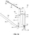
- FIG. 16 is an enlarged isometric view of parts at the base 202 of the wheel chock handling unit 200 in FIG. 15 .
- FIG. 17 is an enlarged side view of parts at the base 202 of the wheel chock handling unit 200 in FIG. 2 when set at a storage position.
- FIG. 18 is a top view of the wheel chock handling unit 200 in FIG. 12 . As can be seen, the follower 270 is now out of engagement with the fixed portion 212.
- FIGS. 19 to 21 are side views showing the wheel chock handling unit 200 in FIG. 2 at various positions.
- the wheel chock 100 is set at a proximal position A in FIG. 19 .
- the lever 252 then causes the extension spring 240 to be at a steeper angle than that if the bottom end of the extension spring 240 would simply be attached to the top edge of the base 202.
- FIG. 20 shows an example when the wheel chock 100 is set at a midway position B.
- FIG. 21 shows an example when the wheel chock 100 is set at a distal position C, for instance at a position where the arm assembly 204 is fully extended.
- the extension spring 240 is at an angle of about 24 degrees with reference to the vertical.
- the angles are 39 degrees and 62 degrees, respectively. Other configurations and arrangements are possible.
- the return force exerted by the main spring assembly 206 on the wheel chock 100 has a vertical component that tends to somewhat lift at least a part of it off the base plate 106. It also has a horizontal component that tends to pull the whole wheel chock 100 sideways off the base plate 106, thus in a transversal direction that is perpendicular to the longitudinal axis 108.
- the wheel 102 ( FIG. 15 ) of the vehicle next the wheel chock 100 can transfer some vibrations to it and the wheel can also slightly move back and forth on various occasions.
- the force-compensation mechanism 250 of the first illustrated example counterbalances the horizontal component by directing at least some of the spring force from the main spring assembly 206 to the side of the movable portion 214. This force-compensation mechanism 250 can also automatically reduce the spring force when the wheel chock 100 is moved sideways.
- FIGS. 22 and 23 are front views showing the wheel chock handling unit 200 when set in the positions depicted in FIGS. 19 and 21 , respectively.
- FIGS. 24 and 25 are enlarged top views of parts at the base 202 of the wheel chock handling unit 200 when set in the positions depicted in FIGS. 19 and 21 , respectively.
- FIG. 24 shows the relative angle between the fixed portion 212 and the movable portion 214 when the wheel chock 100 is set at or near the proximal end of the base pate 106.
- FIG. 25 shows the relative angle between the fixed portion 212 and the and the movable portion 214 when the wheel chock 100 is set at or near the distal end of the base plate 106. As can be seen, the relative angles are not the same.
- the follower 270 being located on the side opposite to that of the base plate 106, governs the angle of the lever 252 and because the movable portion 214 pivots about the vertical pivot axis 215, the angle of the lever 252 changes when the movable portion 214 pivots away from a perpendicular position.
- the second end of the lever 252 is lower in FIG. 24 than in FIG. 25 and lowering the second end decreases the tension in the extension spring 240.
- force-compensation mechanism 250 could be provided as a retrofit kit on an existing articulated spring-assisted device, for instance the ones as suggested in U.S. Pat. Ser. Nos. 7,032,720 and 7,264,092 , as well as U.S. patent application publication No. 2016/0272168 A1 .
- FIG. 26 is an enlarged isometric view of parts at the base 202 of wheel chock handling unit 200 when set at the extended position depicted in FIG. 21 .
- FIG. 27 is a top view of an example of a left-sided wheel chock handling unit 200 when set at an extended position.
- FIG. 28 is an enlarged top view of parts at the base 202 of the wheel chock handling unit 200 in FIG. 27 .
- This implementation is essentially a mirror image of the one shown in FIG. 2 .
- FIG. 29 is a side view showing a wheel chock handling unit 200 similar to that of FIG. 2 but having an additional positioning arrangement 290 at the bottom.
- FIG. 30 is an enlarged side view of the parts at the base 202 of the wheel chock handling unit 200 in FIG. 29 .
- this positioning arrangement 290 includes a chain 292 extending between a bottom extension 294 of the proximal arm 220 and a flange 296 rigidly attached to the fixed swivel portion 212 in this example.
- the flange 296 is located on the same side as that of the follower 270.
- the wheel chock handling unit 200 is in a storage position in FIGS. 29 and 30 , and the chain 292 is under tension to prevent the base 202 from pivoting towards the vehicle.
- the positioning arrangement 290 can also be used to mitigate or even prevent the wheel chock 100 from hitting the fixed swivel portion 212 or the surrounding wall 112 in some implementations. Other configurations and arrangements are possible. Among other things, one or more of the parts of the positioning arrangement 290 can be constructed and/or positioned differently. The positioning arrangement 290 can also be omitted in some implementations. Other variants are possible as well.
- FIG. 31 is a side view showing the wheel chock handling unit 200 in FIG. 29 when the wheel chock 100 is set at a proximal position on the base plate 106.
- FIG. 32 is an enlarged side view of parts of the wheel chock handling unit 200 in FIG. 31 .
- the chain 292 becomes loose when the proximal arm 220 is pivoted away from the substantially vertical position it has in the example when the wheel chock handling unit 200 is in a storage position.
- FIG. 33 is a front view showing the wheel chock handling unit 200 in FIG. 31 .
- FIG. 34 is an enlarged front view of parts at the base 202 of the wheel chock handling unit 200 in FIG. 33 .
- FIG. 35 is a view similar to FIG. 34 but including a schematic illustration of a generic vehicle door 105 for the sake of explanation.
- This door 105 can be one of the doors at the back of the cargo compartment 114 of the vehicle 104 illustrated in FIG. 1 .
- Some doors, like the door 105 schematically illustrated in FIG. 35 may have flanges or the like projecting laterally from the top interior surface thereof. These projecting parts will extend laterally when the door 105 is open.
- the wheel chock handling unit 200 is very similar to the one shown in FIG. 2 .
- the length of the arms 220, 222 and the shape of the top connector member 242 were dimensioned and shaped to fit right under the flange so as to mitigate contact between the flange and the top end of the arm assembly 204.
- the angle of the top portion of the top connector member 242 also contributes to the lower clearance.
- Other configurations and arrangements as possible Among other things, some vehicles may have different kinds of doors and/or some of the doors may not necessarily have flanges near the top edge. Constructing the arm assembly 204 so as to remain below possible obstacles is essentially for the convenience of the end users and such design can be omitted in some implementations. Other variants are possible as well.
- FIG. 36 is an isometric view showing another example of a wheel chock handling unit 200 based on the proposed concept.
- This example is relatively similar to the one shown in FIG. 2 .
- the shape and configuration of the top connector member 242 are different, and there is no bottom connected member since the bottom end of the extension spring 240 is pivotally attached directly to the top end of the lever 252.
- the movable portion 214 of the base 202 is slightly different since the proximal arm 220 will enter the space at the front end of the movable portion 214 at the storage position.
- Other configurations and arrangements are possible.
- one or more of these features can be implemented in the example shown in FIGS. 2 to 35 and/or one or more of the features absent from the example shown in FIG. 36 can be implemented. Other variants are possible as well.
- FIG. 37 is an isometric view showing another example of a wheel chock handling unit 200 based on the proposed concept.
- FIG. 38 is an enlarged isometric view of parts at the base 202 of the wheel chock handling unit 200 in FIG. 37 .
- the force-compensation mechanism 250 includes a counterbalancing spring assembly 300 urging the second end of the leading section 254 of the lever 252 to pivot away from the arm assembly 204.
- the force-compensation mechanism 250 of this illustrated example does not include, among other things, a follower engaging a contact surface.
- the counterbalancing spring assembly 300 includes a compression spring 302, for instance a helical spring, mounted between the lever 252 and the base 202. The top end of the compression spring 302 engages a bracket 304 projecting in front of the lever 252. Other configurations and arrangements are possible.
- the compression spring 302 can be positioned elsewhere and/or be replaced by a similar mechanism, such as a resilient element made of an elastomeric material or the like.
- Other variants include using one or more torsion springs set between the lever 252 and the base 202. Additional variants can be devised as well.
- the lever 252 in the illustrated example includes a forwardly-bended top portion at the end of which the bottom end of the main spring assembly 206 is pivotally mounted.
- the forwardly-bended top portion of this lever 252 thus positions the bottom end of the main spring assembly 206 further away from the wall 112.
- This feature could be implemented in other examples. Nevertheless, variants are possible, and the feature can also be omitted in some implementations.
- moving the arm assembly 204 from the storage position towards the extended position changes the relative position of the opposite ends of the main spring assembly 206 and the orientation of the force vector applied by the main spring assembly 206 on the lever 252.
- the angular position of the lever 252 will change to modify the force coming from the main spring assembly 206.
- the return force exerted by the compression spring 302 will vary based on the angular position of the lever 252 and, in general, will increase as the lever 252 pivots forward.
- the stiffness of the compression spring 302 can be selected to create the desired response.
- the lever 252 can have an unrestricted motion or almost unrestricted motion in some implementations.
- the force-compensation mechanism 250 can include one or more stoppers to limit the angular position of the lever 252 in the forward or the rearward direction, or both.
- a stopper can be a physical element against which the lever 252 abuts or can be the compression spring 302 when fully compressed. Other variants are possible.
- FIG. 37 shows another example for the top connector member 242.
- This model is Y-shaped near the top portion to pass around the top end of the arms 220, 222.
- This top connector member 242 is not necessarily specific to the illustrated example and could be used in other implementations.
- FIG. 39 is an isometric view showing another example of a wheel chock handling unit 200 based on the proposed concept.
- FIG. 40 is an enlarged isometric view of parts at the base 202 of the wheel chock handling unit 200 in FIG. 39 .
- FIG. 41 is an isometric view showing another example of a wheel chock handling unit 200 based on the proposed concept.
- FIG. 42 is an enlarged isometric view of parts at the base 202 of the wheel chock handling unit 200 in FIG. 41 .
Landscapes
- Engineering & Computer Science (AREA)
- Mechanical Engineering (AREA)
- General Engineering & Computer Science (AREA)
- Transportation (AREA)
- Handcart (AREA)
Description
- The technical field relates generally to the handling of wheel chocks used for preventing vehicles from moving away in an unauthorized or accidental manner when they are parked, for instance at a loading area, at a loading dock, in a parking lot, or in any other suitable kinds of driveways or locations.
- Wheels chocks are devices that can be positioned immediately in front of a wheel of a parked vehicle to act as an obstacle in the event of an unauthorized or accidental departure. This event can happen as a result, for instance, of an error or because someone is trying to steal the vehicle. Many other situations exist, including ones where the vehicle movements are caused by other factors, such as trailer creep where motion of a lift truck entering and exiting a trailer can cause separation between the trailer and the dock leveler. Other situations are possible as well.
- Various wheel chock arrangements have been suggested over the years. Examples can be found, for instance, in
EP 2404795 A1, published 11 Jan. 2012 , inU.S. patent application publication No. 2016/0272168 A1 published 22 Sep 2016 and inU.S. patent application publication No. 2018/0086320 A1 published 29 Mar. 2018 . The underside of the wheel chocks can include a plurality of teeth engaging corresponding teeth or other kinds of blocking elements provided on a ground-anchored base plate on which the wheel chocks are set to create an obstacle for vehicles in a departure direction. Other kinds of wheel chocks, arrangements and configurations exist as well. -
U.S. Pat. Ser. Nos. 7,032,720 and7,264,092 , as well asU.S. patent application publication No. 2016/0272168 A1 , include examples of articulated spring-assisted devices for use with wheel chocks. Such devices counterbalance at least part of the weight of the corresponding wheel chock connected at their free end, thereby helping an operator in positioning the wheel chock by hand on the base plate. The operator may be, for instance, the driver of the vehicle or someone working at the site. The wheel chock is initially at a storage position and out of the way of incoming vehicles. - Because a location such as a loading dock may receive vehicles of different sizes and wheel layouts, the distance over which the wheel chock must be transported from its storage position may vary. For instance, a wheel chock may be installed at about 1.2 meters (4 feet) for one vehicle and the same wheel chock could be installed at about 4.2 meters (14 feet) for another. Other distances are possible.
- When the vehicle is authorized to depart, some operators often simply move the wheel chock to the side of the base plate and omit or forget to bring the wheel chock back to the storage position, for instance against or close to the wall at the bottom of the loading area. It is thus often desirable that an articulated spring-assisted device be provided to bring back the wheel chock automatically towards the storage position over the entire range of operation. However, this goal is usually complicated by the fact that the wheel chock generally rests on the ground when simply moved to the side of the base plate. The articulated spring-assisted device should then generate a pulling force sufficient to overcome the friction of the wheel chock on the ground, even at the maximum extended position, to bring it back to the storage position. On the other hand, an excessive spring force can cause the wheel chock to arrive too fast at its storage position, among other things. An excessive spring force can also make the wheel chock harder to move by hand and may tend to lift a portion of the wheel chock when set at some positions along the base plate.
- While existing articulated spring-assisted devices have been useful for the handling of wheel chocks, they required some compromises during their design and/or installation, and this often leads to a number of challenges. Some articulated spring-assisted devices proposed in the past were difficult to adjust and were not always performing optimally over some parts of their range or under certain conditions, among other things. In general, solving one problem often results in a new one being created.
- Overall, there is still room for further improvements in this area of technology.
- In one aspect, there is provided a wheel chock handling unit according to
claim 1. - In another aspect, there is provided a wheel chock restraint system according to claim 14.
- More details on the various aspects, features and advantages of the proposed concept can be found in the following detailed description and the appended figures.
-
-
FIG. 1 is a semi-schematic side view showing an example of a wheel chock located in front of a wheel of a generic vehicle. -
FIG. 2 is an isometric view showing an example of a wheel chock handling unit based on the proposed concept. -
FIG. 3 is a side view showing the wheel chock handling unit inFIG. 2 . -
FIG. 4 is a front view showing the wheel chock handling unit inFIG. 2 . -
FIG. 5 is an enlarged partially exploded isometric view of some of the parts at the base of the wheel chock handling unit inFIG. 2 . -
FIG. 6 is an enlarged side view of the parts at the base of the wheel chock handling unit inFIG. 2 . -
FIG. 7 is an enlarged isometric view of parts at the top end of the wheel chock handling unit inFIG. 2 . -
FIG. 8 is a partially exploded isometric view of some of the parts illustrated inFIG. 7 . -
FIG. 9 is an end view of the mechanical arrangement provided at the top end of the distal arm inFIGS. 7 and8 . -
FIG. 10 is a longitudinal cross section view of the mechanical arrangement taken along line 10-10 inFIG. 9 . -
FIG. 11 is a side view of the mechanical arrangement inFIG. 9 and depicts examples of two different setting positions. -
FIG. 12 is an isometric view of the mechanical arrangement inFIG. 11 . -
FIGS. 13 and 14 are enlarged isometric views of the parts illustrated inFIG. 7 , each corresponding to one of the positions depicted inFIGS. 11 and 12 . -
FIG. 15 is a side view showing the wheel chock handling unit inFIG. 2 when further extended and also showing the wheel chock positioned in front of a generic wheel of a vehicle. -
FIG. 16 is an enlarged isometric view showing parts at the base of the wheel chock handling unit inFIG. 10 . -
FIG. 17 is an enlarged side view of parts at the base of the wheel chock handling unit inFIG. 2 when set at a storage position. -
FIG. 18 is a top view of the wheel chock handling unit inFIG. 17 . -
FIGS. 19 to 21 are side views showing the wheel chock handling unit inFIG. 2 at various positions. -
FIGS. 22 and 23 are front views showing the wheel chock handling unit when set in the positions depicted inFIGS. 19 and 21 , respectively. -
FIGS. 24 and 25 are enlarged top views of parts at the base of the wheel chock handling unit when set in the positions depicted inFIGS. 19 and 21 , respectively. -
FIG. 26 is an enlarged isometric view of parts at the base of the wheel chock handling unit when set at the extended position depicted inFIG. 21 . -
FIG. 27 is a top view showing an example of a left-sided wheel chock handling unit when set at an extended position. -
FIG. 28 is an enlarged top view of parts at the base of the wheel chock handling unit inFIG. 27 . -
FIG. 29 is a side view showing a wheel chock handling unit similar to that ofFIG. 2 but having an additional positioning arrangement at the bottom. -
FIG. 30 is an enlarged side view of the parts at the base of the wheel chock handling unit inFIG. 29 . -
FIG. 31 is a side view showing the wheel chock handling unit inFIG. 29 when the wheel chock is set at a proximal position on the base plate. -
FIG. 32 is an enlarged side view of parts of the wheel chock handling unit inFIG. 31 . -
FIG. 33 is a front view showing the wheel chock handling unit inFIG. 31 . -
FIG. 34 is an enlarged front view of parts at the base of the wheel chock handling unit inFIG. 33 . -
FIG. 35 is a view similar toFIG. 34 but including a schematic illustration of a generic vehicle door for the sake of explanation. -
FIG. 36 is an isometric view showing another example of a wheel chock handling unit based on the proposed concept. -
FIG. 37 is an isometric view showing another example of a wheel chock handling unit based on the proposed concept. -
FIG. 38 is an enlarged isometric view of parts at the base of the wheel chock handling unit illustrated inFIG. 37 . -
FIG. 39 is an isometric view showing another example of a wheel chock handling unit based on the proposed concept. -
FIG. 40 is an enlarged isometric view of parts at the base of the wheel chock handling unit inFIG. 39 . -
FIG. 41 is an isometric view showing another example of a wheel chock handling unit based on the proposed concept. -
FIG. 42 is an enlarged isometric view of parts at the base of the wheel chock handling unit inFIG. 41 . -
FIG. 1 is a semi-schematic side view showing an example of awheel chock 100 located in front of awheel 102 of ageneric vehicle 104, in this case a truck trailer designed to be hauled by a truck tractor. This is only one among a multitude of possible uses for thewheel chock 100. - The wheel chock 100 is provided for preventing the
vehicle 104 from moving away in an unauthorized or accidental manner. The wheel chock 100 is designed to be positioned directly in front of thewheel 102 over a ground-anchoredbase plate 106. Thewheel chock 100 and thebase plate 106 are part of a wheelchock restraint system 150. The wheel chock 100 is in a tire-blocking position inFIG. 1 and prevents thevehicle 104 from moving in a direction of departure. This direction of departure corresponds to thelongitudinal axis 108 in the illustrated example. It should be noted that the departure direction may not always be the forward direction for all vehicles since some wheel chocks may need to be positioned behind a wheel instead of being positioned in front of it. Thebase plate 106 is rigidly anchored to the ground, for instance using bolts or any other suitable arrangement. Other configurations and arrangements are possible as well. - The wheel chock 100 creates an obstacle that must be removed only at the appropriate moment, for instance by the driver of the
vehicle 104 and after thevehicle 104 was authorized to leave. The wheel chock 100 is otherwise left in position immediately in front of thewheel 102 to block it, thereby preventing thewhole vehicle 104 from moving. In some cases, thewheel chock 100 can be bidirectional and provided to prevent a vehicle from moving in two directions. Thewheel chock 100, whether it is bidirectional or not, can also be useful with a vehicle having a swap body configuration. Such vehicle has two basic parts, namely a chassis and a container that can be detached from the chassis. The container has supporting legs to keep it above the ground when detached from the chassis. The wheel chock 100 can be set to prevent the complete vehicle, i.e., the chassis and the container, to leave. It can also be set to prevent the chassis of the vehicle from backing up, in a rearward travel direction, so as to be under the container. Other situations exist as well. For instance, thewheel chock 100 can be used with vehicles that are not truck trailers, including vehicles unrelated to the transport industry. - The
vehicle 104 in the example ofFIG. 1 is shown as being parked at aloading dock 110 and its rear side is adjacent to thewall 112 located at the end of theloading dock 110. It can rest against a cushion or the like, as shown schematically inFIG. 1 at 113. Thewall 112 can be part of a commercial building, for instance a warehouse, a distribution center or the like. Loading docks are not the only locations where wheel chocks can be provided. For instance, wheel chocks can be used with vehicles located in parking areas, truck stops, etc. Other variants are possible as well. - The
vehicle 104 illustrated inFIG. 1 includes acargo compartment 114. Access into thecargo compartment 114 can be made, for instance, using a rear door, which rear door is positioned in registry with a corresponding garage door on thewall 112 when thevehicle 104 is parked at theloading dock 110. The floor inside thecargo compartment 114 and the floor of the corresponding building are often at the same height or at a similar height so that a lift truck or the like can load or unload the cargo therein. A ramp can also be used between both floors if the height difference is too important. Other configurations and arrangements are possible as well. - The wheel chock 100 can include one or more sensors, for instance a sensor to detect the presence of a wheel next to the
wheel chock 100 during operation. Different types of sensors can be used, such as non-contact sensors (photocells) or the like. Using mechanical arrangements are possible as well. The sensor or sensors can be linked to one or more systems, for instance security and safety systems. These systems can use signals from sensors to trigger different functions and/or prevent other systems from operating unless thewheel chock 100 is properly placed next to a wheel. Triggered functions can include, for instance, issuing audible and/or visual alarm signals if a sensor does not indicate a proper positioning of thewheel chock 100 and someone attempts to initiate a task that must only be done if thewheel chock 100 is properly positioned. Signals from the sensor or sensors can also be sent to other active security or safety systems, such as interlocks, locking systems, barriers, etc. They may require the use of identification (ID) cards and/or rely on biometric sensors, such as retina, fingerprints or others. Many other variants are possible as well. - In the example illustrated in
FIG. 1 , thewheel chock 100 is positioned between thewheel 102 and anadjacent wheel 116 located immediately in front of thewheel 102. Thewheel 102 and theadjacent wheel 116 can be part of a tandem axle arrangement. Other configurations and arrangements are possible as well. - Many truck trailers have a dual wheel arrangement where two wheels positioned side-by-side at each end of each axle. In this case, the word "wheel" used in the context of the
wheel chock 100 refers to the exterior wheel and/or the interior wheel. Most implementations will have thewheel chock 100 in position with only one of the wheels at a time, often the exterior wheel because of its proximity to the side of a vehicle. However, some could position thewheel chock 100 simultaneously in front of the two side-by-side wheels in some situations, or even only in front of the interior wheel in others. It is thus intended that the word "wheel" in a singular form means either only one of the side-by-side wheels or both side-by-side wheels simultaneously in the context of a dual wheel arrangement. -
FIG. 2 is an isometric view showing an example of a wheelchock handling unit 200 based on the proposed concept. The wheelchock handling unit 200 can be a part of a wheelchock restraint system 150 to help handle thewheel chock 100. The wheel chock 100 can be relatively heavy and the wheelchock handling unit 200 can counterbalance at least part of the weight of thewheel chock 100 to help the operator in positioning thewheel chock 100 at the appropriate location on thebase plate 106. Other configurations and arrangements are possible as well. Among other things, the wheelchock handling unit 200 could be considered not to be part of the wheel chockrestraint system 150 in some implementations. Other variants are possible as well. - As can be seen in
FIG. 2 , thebase plate 106 in the illustrated example has an elongated shape and extends linearly along thelongitudinal axis 108. Thebase plate 106 of the illustrated example also includes a plurality ofstoppers 106a transversally disposed thereon and that are spaced apart from one another along thelongitudinal axis 108, for instance regularly spaced individually or in pairs. Thestoppers 106a project from above the top surface of a plurality of plates. They are configured and disposed to cooperate withcorresponding teeth 100a (FIG. 17 ) provided underneath thewheel chock 100 so as to create a latching engagement between them when thewheel chock 100 is pushed forcefully in at least one direction. The illustratedbase plate 106 allows thewheel chock 100 to be placed at various distances from thewall 112 to accommodate vehicles of different sizes and wheel layouts. Other configurations and arrangements are possible as well. Among other things, thebase plate 106 and/or thestoppers 106a could be shaped and constructed differently in other implementations. For instance, eachstopper 106a could be in the form of two or more spaced apart segments instead of extending uninterruptedly across the width of thebase plate 106 as shown. Thebase plate 106 could be much shorter in length and even be provided in spaced-apart sections. Thebase plate 106 may be provided without a peripheral rim or with a rim that is different from the illustrated example. Some implementations could have only one possible position for thewheel chock 100. Still, a base plate could be omitted in some implementations. Other variants are possible as well. - The illustrated wheel
chock handling unit 200 includes abase 202, an articulatedcantilever arm assembly 204 and amain spring assembly 206. - The
base 202 secures the wheelchock handling unit 200 to a fixed location, for instance thewall 112 located at the end of the loading dock 110 (FIG. 1 ). Thebase 202 is generally positioned slightly above the ground and can be attached to thewall 112 using different methods. Other configurations and arrangements are possible as well. Among other things, thewall 112 is only one example of a fixed location and it is possible to secure the wheelchock handling unit 200 to another kind of fixed location. For instance, one can use a stand anchored to the ground or attached to any other suitable location. Furthermore, the term "fixed location" includes any suitable structure capable of holding the wheelchock handling unit 200 during operation. A fixed location can include, for instance, a large concrete block resting on the ground. Although the concrete block could possibly be moved using appropriate tools or equipment, it still constitutes a fixed location in the context. Other variants are possible as well. The following description mainly refers thewall 112 for the sake of simplicity. Hence, the term "wall" is only used herein in a generic and non-limitative way. -
FIGS. 3 and4 are, respectively, a side view and a front view showing the wheelchock handling unit 200 inFIG. 2 .FIG. 5 is an enlarged partially exploded isometric view of some of the parts at thebase 202 of the wheelchock handling unit 200 inFIG. 2 . - Depending on the implementation, the base 202 can be entirely immovable or can include a movable part as shown in the illustrated example. In the example shown in
FIGS. 2 to 5 , thebase 202 includes aswivel support 210 having a fixedportion 212 and amovable portion 214 that is pivotally mounted to the fixedportion 212 for angular displacement about a substantiallyvertical pivot axis 215. The fixedportion 212 can be in the form of a large rectangular plate with a plurality of spaced-apart holes 212a provided near its periphery to receive bolts or other kinds of fasteners, as shown. Themovable portion 214 can include a rigid structure having two spaced apart and parallel lateralvertical plates 214a that are rigidly attached using top and bottomintermediary members 214b in the illustrated example. Theswivel support 210 also includes avertical axle 216 that is part of a hinge mechanically connecting the fixedportion 212 and themovable portion 214. Other configurations and arrangements are possible as well. Among other things, thebase 202, as aforesaid, can be immovable, i.e., static, in some implementations. - The
arm assembly 204 has a first end pivotally mounted to thebase 202 for angular displacement of thearm assembly 204 in a substantially vertical plane between a retracted storage position and an extended position. In the illustrated example, the first end of thearm assembly 204 is pivotally mounted at the bottom of themovable portion 214 using abottom joint 218. The first end of thearm assembly 204 pivots about a substantiallyhorizontal pivot axis 219 located at a bottom distal corner of the base 202 in the illustrated example. The bottom joint 218 can include a sleeve 260 (FIG. 26 ) or the like that is rigidly attached to the side of theproximal arm 220 and a bolt or the like, for instance a bolt with a bushing or a bearing, passes inside the sleeve to pivotally attach the bottom end of theproximal arm 220 to thevertical plates 214a. The bottom front edges of thevertical plates 214a also include a corresponding flanged portion. Other configurations and arrangements are possible. Among other things, the bottom joint 218 can be positioned and constructed differently. Other variants are possible as well. - A
height adjustment arrangement 221 is provided in the illustrated example to fine-tune the vertical position of thebottom joint 218. Parts of theheight adjustment arrangement 221 can be seen inFIG. 5 . The vertical position of each end of the bottom joint 218 can be adjusted by raising or lowering a corresponding one of the side plates. This can be useful, among other things, to align theproximal arm 220 if required. Other configurations and arrangements are possible. This feature can be omitted in some implementations. Other variants are possible. - The distal end of the
arm assembly 204 is mechanically connected to thewheel chock 100. This distal end is the free end of thearm assembly 204, thus the end located away from thebase 202. The wheel chock 100 can be mechanically connected to the side of the second end using a shortrigid linking member 208 or the like, as shown for instance inFIG. 4 . One end of the linkingmember 208 can be rigidly attached to the side of thewheel chock 100, near the top thereof, and the opposite end can be attached to thedistal arm 222 using a ball joint 209 or the like. The ball joint 209 can facilitate the final positioning of thewheel chock 100. Other configurations and arrangements are possible as well. Among other things, thewheel chock 100 can be attached differently to thearm assembly 204. The linking member and/or the ball joint can be positioned or constructed differently. One or even both of them can even be omitted in some implementations. - The illustrated
arm assembly 204 includes aproximal arm 220 and adistal arm 222 that are pivotally attached at a firstupper joint 224. The first upper joint 224 pivots about a substantiallyhorizontal pivot axis 226. Theproximal arm 220 has opposite top and bottom ends and thedistal arm 222 also has opposite top and bottom ends. The bottom end of theproximal arm 220 corresponds to the first end of thearm assembly 204 and the bottom end of thedistal arm 222 corresponds to the second end of thearm assembly 204. Also, in the illustrated example, theproximal arm 220 and thedistal arm 222 are each in the form of an elongated single beam member, for instance one having a substantially square or rectangular cross section. They are made of a rigid material, such as a metal, and are rectilinear. Thedistal arm 222 is slightly smaller in length than theproximal arm 220. Other materials, configurations and arrangements are possible as well. Among other things, thearms - In the illustrated example, the first upper joint 224 is positioned slightly below the top end of the
distal arm 222, namely at a first location on thedistal arm 222 that is slightly offset from the top end of thedistal arm 222. Variants are possible. - The
main spring assembly 206 extends generally between the top end of thearm assembly 204 and the top side of thebase 202. Themain spring assembly 206 is the mechanism that generates the forces to counterbalance at least part of the weight of thewheel chock 100 and to bring the wheel chock back towards thewall 112 when thewheel chock 100 is removed from thebase plate 106 once the vehicle is authorized to depart. Themain spring assembly 206 urges thearm assembly 204 towards its storage position, namely the position where thewheel chock 100 is brought back towards thewall 112 and where botharms - To move the
arm assembly 204 away from the storage position, the operator can grab one of thehandles 223 located on the side of thedistal arm 222 or thedistal arm 222 itself and walk towards the setting point of thewheel chock 100, thereby moving in a general direction that is substantially parallel to thelongitudinal axis 108. This will extend thearm assembly 204 and change the elongation of themain spring assembly 206. Extending themain spring assembly 206 increases the return force it generates. The wheel chock 100 is often entirely above the ground when thearm assembly 204 is moved by hand by the operator but this is not the only possible method and, among other things, thewheel chock 100 can partially contact the ground when carried by the operator. Other methods are possible as well. Thehandles 223 can be positioned differently, and they can even be omitted in some implementations. Other variants are possible as well. - The illustrated
main spring assembly 206 has a top end pivotally mounted to thedistal arm 222 at a second location within a portion extending from the first location to the top end of thedistal arm 222. It is pivotally attached through a second upper joint 246, and it can pivot about a substantiallyhorizontal pivot axis 248. Nevertheless, one can also attach the top end of themain spring assembly 206 to theproximal arm 220 in some implementations. Other configurations and arrangements are possible as well. - In the illustrated example, the
main spring assembly 206 includes asingle extension spring 240, for instance a helical spring. Other configurations and arrangements are possible as well. For instance, some implementations can include two or more springs provided side-by-side. Other kinds of springs can be used. - The
extension spring 240 is shorter than the overall length of themain spring assembly 206 in the illustrated example and themain spring assembly 206 includes atop connector member 242. The top end of theextension spring 240 is pivotally attached to the bottom end of thetop connector member 242, and the top end of thetop connector member 242 is pivotally attached to the secondupper joint 246. The bottom end of theextension spring 240 in the illustrated example is pivotally attached to abottom connector member 243, for instance using an eyelet through a transversal bolt or axle. Thisbottom connector member 243 includes a turnbuckle in the illustrated example to fine-tune the tension from theextension spring 240. Other configurations and arrangements are possible. For instance, thetop connector member 242 and/or thebottom connector member 243 can be omitted in some implementations. The turnbuckle could be provided on thetop connector member 242 or even be omitted in some implementations. Other kinds of pivot connectors are possible. Other variants are possible as well. - In the illustrated example, the
top connector member 242 is substantially L-shaped near its top end and is substantially U-shaped in cross section at least near to top end to prevent it from interfering with theproximal arm 220 and thedistal arm 222 when thearm assembly 204 is at or near the storage position. Variants are possible as well. For instance, thetop connector member 242 can include two side portions that are positioned on the sides of thearm assembly 204 when it is at or near the storage position. Other configurations and arrangements are possible as well. - A
resilient spacer 244 is provided on thewheel chock 100 of the illustrated example, as shown inFIG. 3 . Thisspacer 244 can be made of rubber or of another suitable material. It is positioned and disposed to keep thewheel chock 100 slightly away from a wheel so as to mitigate the risks of having thewheel chock 100 becoming stuck under the wheel due to the weight of the vehicle increasing as it is loaded. Other configurations and arrangements are possible. Among other things, thespacer 244 can be omitted in some implementations. Other variants are possible as well. - A resilient bumper 245 (
FIG. 5 ) can be provided on the bottom front side of theproximal arm 220 of the illustrated example, as shown. Thisbumper 245 can be useful for preventing a direct contact between the corresponding main surfaces of the twoarms arm assembly 204 gets to the storage position. Other configurations and arrangements are possible. Among other things, theresilient bumper 245 can be positioned or constructed differently. It can also be omitted in some implementations. Other variants are possible as well. - The wheel
chock handling unit 200 further includes a force-compensation mechanism 250. This force-compensation mechanism 250 includes alever 252 that is pivotally mounted to thebase 202 for angular displacement in a plane that is substantially parallel to that of thearm assembly 204. In the illustrated example, thelever 252 is pivotally mounted to themovable portion 214 of theswivel support 210 and pivots about a substantiallyhorizontal pivot axis 253. Thelever 252 can also be provided on a base 202 that is immovable. Other configurations and arrangements are possible. - A
bracket 258 is attached to theproximal arm 220. Thisbracket 258 projects from one edge of theproximal arm 220 towards thedistal arm 222, more precisely from the edge that is opposite to the side from which thewheel chock 100 extends. Because thearm assembly 204 generally supports at least some of the weight of thewheel chock 100, if not the entire weight thereof, when it is in the storage position, thebracket 258 helps keep the twoarms -
FIG. 6 is an enlarged side view of the parts at thebase 202 of the wheelchock handling unit 200 inFIG. 2 - The force-
compensation mechanism 250 of the wheelchock handling unit 200 can be implemented in different ways. In the example shown for instance inFIGS. 2 to 6 , thelever 252 includes an elongated leadingsection 254 interposed between the bottom of themain spring assembly 206 and thebase 202. This leadingsection 254 has opposite first and second ends. The first end of the leadingsection 254 is pivotally mounted to thebase 202. The bottom of themain spring assembly 206 is pivotally mounted to thelever 252 at or about the second end of the leadingsection 254, thus located away from the first end. The second end of the leadingsection 254 is vertically higher than the top edge of thebase 202. Other configurations and arrangements are possible. Among other things, the bottom end of themain spring assembly 206 does not necessarily need to be at the top extremity of thelever 252. The second end of the leadingsection 254 can be a location that is more or less distant from the top end of thelever 252. One can also provide multiple possible positions for receiving the bottom end of themain spring assembly 206, each at a slightly different height, for obtaining the settings. Each of these positions, in the context, would still fit within the meaning of the second end. Other variants are possible as well. - The
lever 252 in the illustrated example includes anelongated trailing section 256 in addition to the leadingsection 254. The trailingsection 256 has opposite first and second ends, the first end being located next to the first end of the leadingsection 254. The trailingsection 256 includes an upper portion and a bottom portion. In the illustrated example, the leadingsection 254 and an upper portion of the trailingsection 256 are in registry with one another. They are also made integral with one another. Other configurations and arrangements are possible. - Still, in the illustrated example, the bottom portion of the trailing
section 256 is substantially L-shaped near the bottom, thus near the second end of the trailingsection 256. This second end is oriented towards thewall 112 and it corresponds to the bottommost end of thelever 252. Other configurations and arrangements are possible as well. - The force-
compensation mechanism 250 shown inFIGS. 2 to 6 includes afollower 270 mounted to thelever 252 at the second end of the trailingsection 256 or close to it. Thefollower 270 projecting towards acontact surface 272 located on the fixedportion 212 of theswivel support 210. Alternatively, thecontact surface 272 can be located adjacent to the fixedportion 212 or be provided on both the fixedportion 212 and an adjacent location. Thecontact surface 272 is the area that can be engaged by the free end of thefollower 270. Thecontact surface 272 can be machined or not. It can be, as illustrated, simply the outer flat surface of the fixedportion 212. Variants are possible. - The
follower 270 of the illustrated example includes a threaded bolt having a head portion and a threaded shank. The threaded shank is mounted into a corresponding threaded element, for instance a nut secured to thelever 252, or into a corresponding threaded hole provided at the bottom end of thelever 252. The head portion of the bolt has a smooth hemispheric outer surface, and thefollower 270 engages thecontact surface 272 through this outer surface. Thefollower 270 is adjustable in length to fine-tune the settings. Other configurations and arrangements are possible. For instance, thefollower 270 could be made non-adjustable in some implementations. Thefollower 270 can also be formed, in some implementations, directly by the free end at the bottom of thelever 252 engaging thecontact surface 272. - The
base 202 of the wheelchock handling unit 200 in the illustrated example includes aswivel support 210 and thefollower 270 is only located on either a left side or a right side of theswivel support 210, namely on the side opposite to that of thebase plate 106. Thefollower 270 engages thecontact surface 272 at least when thearm assembly 204 is out of the storage position to press on thecontact surface 272. Then, pivoting thearm assembly 204 will also change the position of thefollower 270 on thecontact surface 272. Some implementations can be configured or set so that thefollower 270 remains engaged with thecontact surface 272 at the storage position. Other configurations and arrangements are possible. - The
lever 252 can be double sided, as shown in the illustrated example. One side is located on the right side of theswivel support 210 and the other side is located on the left side of theswivel support 210. This double-sided lever 252 includes a first transversal member extending between the two sides of thelever 252 and to which themain spring assembly 206 is attached, a second transversal member extending between the two sides and through which thelever 252 is pivotally attached to thebase 202, and a third transversal member extending between the bottom ends of the two sides. Other configurations and arrangements are possible. - The
lever 252 of the force-compensation mechanism 250 shown inFIGS. 2 to 6 is designed to pivot, when thearm assembly 204 is at or close to the storage position, so as to disengage thefollower 270 from thecontact surface 272. This can be implemented in different ways. One is to have alever 252 where the trailingsection 256 at the bottom is made heavier than the leadingsection 254 at the top. Gravity will tend to pivot thelever 252 when the spring force from themain spring assembly 206 becomes relatively low. The direction of the force is another factor and thelever 252 can be forced to pivot, even if the spring force remains relatively high, if the spring force vector moves in front of the pivot point of thelever 252. Other configurations and arrangements are possible as well. Among other things, one could use a return spring for specifically pivoting thelever 252 when thearm assembly 204 is at or close to the storage position. The trailingsection 256 could a length equal or shorter than that of the leadingsection 254. Other variants are possible as well. - As can be appreciated, the
follower 270 of the illustrated example, among other things, helps keep the proper orientation of thearm assembly 204 and, in use, can mitigate or even prevent the spring force from moving thewheel chock 100 sideways, particularly when there are small back-and-forth motions of thewheel 102, for instance when moving cargo inside the vehicle. These small movements, combined with the spring force, tend to bring thewheel chock 100 to the side. However, because thefollower 270 pushes on the fixedportion 212 at a location on the bottom side of thevertical axle 216, which side is opposite to the one where thewheel chock 100 is located, thearms follower 270 would be placed on the other side if thewheel chock 100 is provided on the other side at the end of thedistal arm 222. -
FIG. 7 is an enlarged isometric view of parts at the top end of the wheelchock handling unit 200 inFIG. 2 .FIG. 7 shows, among other things, anadjustable stopper 228 to limit the relative angle between theproximal arm 220 and thedistal arm 222 when thearm assembly 204 is at the fully extended position. The illustrated example shows that thestopper 228 includes a bolt that is generally parallel to theproximal arm 220 and that is threaded in a holdingmember 229 attached over theproximal arm 220. The parts are configured and disposed so that the top end of thedistal arm 222 engages the head of the bolt of thestopper 228 at the fully extended position. Changing the position of the bolt of thestopper 228 allows increasing or decreasing this maximum distance between thewheel chock 100 and thewall 112. Other configurations and arrangements are possible. Among other things, thestopper 228 can be constructed differently and/or positioned elsewhere. It may not necessarily adjustable in all implementations and may also be omitted in others. Other variants are possible as well. -
FIG. 7 also shows an example of amechanical arrangement 230 for adjusting the position of the secondupper joint 246. Themechanical arrangement 230 is attached at the top end of thedistal arm 222 inFIG. 7 and the first and secondupper joints mechanical arrangement 230 can be bolted or otherwise attached to thedistal arm 222 and, in the context, can be considered to be a part of thedistal arm 222 itself. Other configurations and arrangements are possible. For instance, one can omit the mechanical arrangement entirely in some implementations or use a completely different method for mounting theupper joints -
FIG. 8 is a partially exploded isometric view of some of the parts illustrated inFIG. 7 . The illustratedmechanical arrangement 230 includes two oppositecomplementary members transversal axle 233 extending at the end of thetop connector member 242 can be pivotally supported. Thebottom member 232 fits into anelongated guide 234 extending at the top end of thedistal arm 222. The position of thebottom member 232 within theelongated guide 234 can be changed using abolt 235. Thetop member 231 can be attached onto thebottom member 232 usingfasteners 236. Aguide bolt 237 extends through a corresponding slot made at the bottom of theguide 234. Thismechanical arrangement 230 can be useful to fine-tune the wheelchock handling unit 200 from one installation to another. Other configurations and arrangements are possible. For instance, different kinds of adjustment mechanisms can be used instead of the ones being shown. Themechanical arrangement 230 can also be omitted entirely in some implementations. Other variants are possible as well. - As can be seen, the first upper joint 224 includes a
sleeve 238 that is rigidly attached to a laterally projectingmember 239. Themember 239 provides the horizontal spacing for the twoarms -
FIG. 8 shows that thearm assembly 204 can include asafety cable 280 extending between the twoarms cable 280 is provided in the illustrated example in the event someone mishandles thewheel chock 100 and creates an unlikely situation where thewheel chock 100 is grabbed by thevehicle 104 as it departs, thereby causing the twoarms proximal arm 220 from returning forcefully towards the storage position. Generally, if such rupture of thearm assembly 204 occurs, the loud noise associated with the parts breaking is noticed by the driver andvehicle 104 is then immediately stopped. A similar cable can be provided between thewheel chock 100 and thedistal arm 222. Other configurations and arrangements are possible. Among other things, thecable 280 can be positioned or constructed differently. It can also be omitted in some implementations. Other variants are possible as well. -
FIG. 9 is an end view of themechanical arrangement 230 provided at the top end of thedistal arm 222 inFIGS. 7 and8 .FIG. 10 is a longitudinal cross section view of themechanical arrangement 230 taken along line 10-10 inFIG. 9 . -
FIG. 11 is a side view of themechanical arrangement 230 inFIG. 9 and depicts examples of two different setting positions.FIG. 12 is an isometric view of themechanical arrangement 230 inFIG. 11 .FIGS. 13 and 14 are enlarged isometric views of the parts illustrated inFIG. 7 , each corresponding to one of the positions depicted inFIGS. 11 and 12 . -
FIG. 15 is a side view shows the wheelchock handling unit 200 inFIG. 2 when further extended and also showing thewheel chock 100 positioned in front of ageneric wheel 102 of a vehicle. It shows, among other things, thewheel 102 engaging thespacer 244. Thecable 280 can also be seen. -
FIG. 16 is an enlarged isometric view of parts at thebase 202 of the wheelchock handling unit 200 inFIG. 15 . -
FIG. 17 is an enlarged side view of parts at thebase 202 of the wheelchock handling unit 200 inFIG. 2 when set at a storage position.FIG. 18 is a top view of the wheelchock handling unit 200 inFIG. 12 . As can be seen, thefollower 270 is now out of engagement with the fixedportion 212. -
FIGS. 19 to 21 are side views showing the wheelchock handling unit 200 inFIG. 2 at various positions. As can be seen, thewheel chock 100 is set at a proximal position A inFIG. 19 . Thelever 252 then causes theextension spring 240 to be at a steeper angle than that if the bottom end of theextension spring 240 would simply be attached to the top edge of thebase 202.FIG. 20 shows an example when thewheel chock 100 is set at a midway position B.FIG. 21 shows an example when thewheel chock 100 is set at a distal position C, for instance at a position where thearm assembly 204 is fully extended. InFIG. 19 , theextension spring 240 is at an angle of about 24 degrees with reference to the vertical. InFIGS. 20 and 21 , the angles are 39 degrees and 62 degrees, respectively. Other configurations and arrangements are possible. - When the
wheel chock 100 is on thebase plate 106 at a relatively short distance from its storage position, the return force exerted by themain spring assembly 206 on thewheel chock 100 has a vertical component that tends to somewhat lift at least a part of it off thebase plate 106. It also has a horizontal component that tends to pull the whole wheel chock 100 sideways off thebase plate 106, thus in a transversal direction that is perpendicular to thelongitudinal axis 108. Moreover, the wheel 102 (FIG. 15 ) of the vehicle next thewheel chock 100 can transfer some vibrations to it and the wheel can also slightly move back and forth on various occasions. These small repetitive movements can originate from the suspension of the vehicle due to weight variations and/or a lift truck entering and exiting the interior of the vehicle. These factors could bring thewheel chock 100 progressively off thebase plate 106, particularly if thewheel chock 100 was not suitably positioned by the operator. The force-compensation mechanism 250 of the first illustrated example counterbalances the horizontal component by directing at least some of the spring force from themain spring assembly 206 to the side of themovable portion 214. This force-compensation mechanism 250 can also automatically reduce the spring force when thewheel chock 100 is moved sideways. -
FIGS. 22 and 23 are front views showing the wheelchock handling unit 200 when set in the positions depicted inFIGS. 19 and 21 , respectively. -
FIGS. 24 and 25 are enlarged top views of parts at thebase 202 of the wheelchock handling unit 200 when set in the positions depicted inFIGS. 19 and 21 , respectively.FIG. 24 shows the relative angle between the fixedportion 212 and themovable portion 214 when thewheel chock 100 is set at or near the proximal end of thebase pate 106.FIG. 25 shows the relative angle between the fixedportion 212 and the and themovable portion 214 when thewheel chock 100 is set at or near the distal end of thebase plate 106. As can be seen, the relative angles are not the same. - The
follower 270, being located on the side opposite to that of thebase plate 106, governs the angle of thelever 252 and because themovable portion 214 pivots about thevertical pivot axis 215, the angle of thelever 252 changes when themovable portion 214 pivots away from a perpendicular position. The second end of thelever 252 is lower inFIG. 24 than inFIG. 25 and lowering the second end decreases the tension in theextension spring 240. - It should be noted that the force-
compensation mechanism 250 could be provided as a retrofit kit on an existing articulated spring-assisted device, for instance the ones as suggested inU.S. Pat. Ser. Nos. 7,032,720 and7,264,092 , as well asU.S. patent application publication No. 2016/0272168 A1 . -
FIG. 26 is an enlarged isometric view of parts at thebase 202 of wheelchock handling unit 200 when set at the extended position depicted inFIG. 21 . -
FIG. 27 is a top view of an example of a left-sided wheelchock handling unit 200 when set at an extended position.FIG. 28 is an enlarged top view of parts at thebase 202 of the wheelchock handling unit 200 inFIG. 27 . This implementation is essentially a mirror image of the one shown inFIG. 2 . -
FIG. 29 is a side view showing a wheelchock handling unit 200 similar to that ofFIG. 2 but having anadditional positioning arrangement 290 at the bottom.FIG. 30 is an enlarged side view of the parts at thebase 202 of the wheelchock handling unit 200 inFIG. 29 . As can be seen, thispositioning arrangement 290 includes achain 292 extending between abottom extension 294 of theproximal arm 220 and aflange 296 rigidly attached to the fixedswivel portion 212 in this example. Theflange 296 is located on the same side as that of thefollower 270. The wheelchock handling unit 200 is in a storage position inFIGS. 29 and 30 , and thechain 292 is under tension to prevent the base 202 from pivoting towards the vehicle. This can prevent, for instance, the wheelchock handling unit 200 from becoming stuck or damaged by the rear end of a vehicle because the vehicle is very large and/or it is not properly aligned with the loading dock and thearm assembly 204 was pivoted towards the vehicle, notwithstanding the presence of strong guarding elements or protectors secured to thewall 112. Thepositioning arrangement 290 can also be used to mitigate or even prevent the wheel chock 100 from hitting the fixedswivel portion 212 or the surroundingwall 112 in some implementations. Other configurations and arrangements are possible. Among other things, one or more of the parts of thepositioning arrangement 290 can be constructed and/or positioned differently. Thepositioning arrangement 290 can also be omitted in some implementations. Other variants are possible as well. -
FIG. 31 is a side view showing the wheelchock handling unit 200 inFIG. 29 when thewheel chock 100 is set at a proximal position on thebase plate 106.FIG. 32 is an enlarged side view of parts of the wheelchock handling unit 200 inFIG. 31 . As can be seen, thechain 292 becomes loose when theproximal arm 220 is pivoted away from the substantially vertical position it has in the example when the wheelchock handling unit 200 is in a storage position. -
FIG. 33 is a front view showing the wheelchock handling unit 200 inFIG. 31 .FIG. 34 is an enlarged front view of parts at thebase 202 of the wheelchock handling unit 200 inFIG. 33 . -
FIG. 35 is a view similar toFIG. 34 but including a schematic illustration of ageneric vehicle door 105 for the sake of explanation. Thisdoor 105 can be one of the doors at the back of thecargo compartment 114 of thevehicle 104 illustrated inFIG. 1 . Some doors, like thedoor 105 schematically illustrated inFIG. 35 , may have flanges or the like projecting laterally from the top interior surface thereof. These projecting parts will extend laterally when thedoor 105 is open. InFIG. 35 , the wheelchock handling unit 200 is very similar to the one shown inFIG. 2 . The length of thearms top connector member 242 were dimensioned and shaped to fit right under the flange so as to mitigate contact between the flange and the top end of thearm assembly 204. The angle of the top portion of thetop connector member 242 also contributes to the lower clearance. Other configurations and arrangements as possible. Among other things, some vehicles may have different kinds of doors and/or some of the doors may not necessarily have flanges near the top edge. Constructing thearm assembly 204 so as to remain below possible obstacles is essentially for the convenience of the end users and such design can be omitted in some implementations. Other variants are possible as well. -
FIG. 36 is an isometric view showing another example of a wheelchock handling unit 200 based on the proposed concept. This example is relatively similar to the one shown inFIG. 2 . However, the shape and configuration of thetop connector member 242 are different, and there is no bottom connected member since the bottom end of theextension spring 240 is pivotally attached directly to the top end of thelever 252. Also, themovable portion 214 of thebase 202 is slightly different since theproximal arm 220 will enter the space at the front end of themovable portion 214 at the storage position. Other configurations and arrangements are possible. Among other things, one or more of these features can be implemented in the example shown inFIGS. 2 to 35 and/or one or more of the features absent from the example shown inFIG. 36 can be implemented. Other variants are possible as well. -
FIG. 37 is an isometric view showing another example of a wheelchock handling unit 200 based on the proposed concept.FIG. 38 is an enlarged isometric view of parts at thebase 202 of the wheelchock handling unit 200 inFIG. 37 . - In the example shown in
FIGS. 37 and38 , the force-compensation mechanism 250 includes a counterbalancingspring assembly 300 urging the second end of the leadingsection 254 of thelever 252 to pivot away from thearm assembly 204. The force-compensation mechanism 250 of this illustrated example does not include, among other things, a follower engaging a contact surface. The counterbalancingspring assembly 300 includes acompression spring 302, for instance a helical spring, mounted between thelever 252 and thebase 202. The top end of thecompression spring 302 engages abracket 304 projecting in front of thelever 252. Other configurations and arrangements are possible. For instance, thecompression spring 302 can be positioned elsewhere and/or be replaced by a similar mechanism, such as a resilient element made of an elastomeric material or the like. Other variants include using one or more torsion springs set between thelever 252 and thebase 202. Additional variants can be devised as well. - The
lever 252 in the illustrated example includes a forwardly-bended top portion at the end of which the bottom end of themain spring assembly 206 is pivotally mounted. The forwardly-bended top portion of thislever 252 thus positions the bottom end of themain spring assembly 206 further away from thewall 112. This feature could be implemented in other examples. Nevertheless, variants are possible, and the feature can also be omitted in some implementations. - In use, moving the
arm assembly 204 from the storage position towards the extended position changes the relative position of the opposite ends of themain spring assembly 206 and the orientation of the force vector applied by themain spring assembly 206 on thelever 252. The angular position of thelever 252 will change to modify the force coming from themain spring assembly 206. The return force exerted by thecompression spring 302 will vary based on the angular position of thelever 252 and, in general, will increase as thelever 252 pivots forward. The stiffness of thecompression spring 302 can be selected to create the desired response. Thelever 252 can have an unrestricted motion or almost unrestricted motion in some implementations. Alternatively, the force-compensation mechanism 250 can include one or more stoppers to limit the angular position of thelever 252 in the forward or the rearward direction, or both. A stopper can be a physical element against which thelever 252 abuts or can be thecompression spring 302 when fully compressed. Other variants are possible. -
FIG. 37 shows another example for thetop connector member 242. This model is Y-shaped near the top portion to pass around the top end of thearms top connector member 242 is not necessarily specific to the illustrated example and could be used in other implementations. -
FIG. 39 is an isometric view showing another example of a wheelchock handling unit 200 based on the proposed concept.FIG. 40 is an enlarged isometric view of parts at thebase 202 of the wheelchock handling unit 200 inFIG. 39 . -
FIG. 41 is an isometric view showing another example of a wheelchock handling unit 200 based on the proposed concept.FIG. 42 is an enlarged isometric view of parts at thebase 202 of the wheelchock handling unit 200 inFIG. 41 . - Overall, implementing the proposed concept results in wheel chock handling
units 200 that are more versatile and that can perform much better over the entire range of operation than ever before. -
- 100
- wheel chock
- 100a
- tooth (under the wheel chock)
- 102
- wheel
- 104
- vehicle
- 105
- door (of the vehicle)
- 106
- base plate
- 106a
- stopper (on the base plate)
- 108
- longitudinal axis
- 110
- loading dock
- 112
- wall
- 113
- cushion
- 114
- cargo compartment
- 116
- adjacent wheel
- 150
- wheel chock restraint system
- 200
- wheel chock handling unit
- 202
- base
- 204
- articulated cantilever arm assembly
- 206
- main spring assembly
- 208
- linking member
- 209
- ball joint
- 210
- swivel support
- 212
- fixed portion (of swivel support)
- 212a
- hole
- 214
- movable portion (of swivel support)
- 214a
- vertical plate (of movable portion)
- 214b
- top and bottom intermediary member (of movable portion)
- 215
- vertical pivot axis
- 216
- vertical axle (of swivel support)
- 218
- bottom joint
- 219
- horizontal pivot axis (of bottom joint)
- 220
- proximal arm
- 221
- height adjustment arrangement
- 222
- distal arm
- 223
- handle
- 224
- first upper joint
- 226
- horizontal pivot axis (of first upper joint)
- 228
- stopper
- 229
- holding member
- 230
- mechanical arrangement
- 231
- top member
- 232
- bottom member
- 233
- transversal axis
- 234
- elongated guide
- 235
- bolt
- 236
- fastener
- 237
- guide bolt
- 238
- sleeve
- 239
- laterally projecting member
- 240
- extension spring
- 242
- top connector member
- 243
- bottom connector member
- 244
- resilient spacer
- 245
- resilient bumper
- 246
- second upper joint
- 248
- horizontal pivot axis (of second upper joint)
- 250
- force-compensation mechanism
- 252
- lever
- 253
- horizontal pivot axis (of lever)
- 254
- leading section
- 256
- trailing section
- 258
- bracket
- 260
- sleeve
- 270
- follower
- 272
- contact surface
- 280
- cable
- 290
- positioning arrangement
- 292
- chain
- 294
- bottom extension
- 296
- flange
- 300
- counterbalancing spring assembly
- 302
- compression spring (of counterbalancing spring assembly)
- 304
- bracket
- 306
- stopper
- 308
- elongated member
Claims (15)
- A wheel chock handling unit (200) for use with a wheel chock (100), the wheel chock handling unit (200) including:a base (202);an articulated cantilever arm assembly (204) having opposite first and second ends, the first end being pivotally mounted to the base (202) for angular displacement of the arm assembly (204) in a substantially vertical plane between a storage position and an extended position;a main spring assembly (206) extending between the arm assembly (204) and the base (202); and being characterized in that it further comprises:
a force-compensation mechanism (250) including a lever (252) having at least an elongated leading section (254) interposed between the main spring assembly (206) and the base (202), the leading section (254) having opposite first and second ends, the first end of the leading section (254) being pivotally mounted to the base (202) for angular displacement of the lever (252) in a plane that is substantially parallel to that of the arm assembly (204), the main spring assembly (206) being pivotally mounted to the lever (252) at or about the second end of the leading section (254). - The wheel chock handling unit (200) as defined in claim 1, wherein the second end of the leading section (254) of the lever (252) is located above the base (202).
- The wheel chock handling unit (200) as defined in claim 1 or 2, wherein the arm assembly (204) includes a proximal arm (220) and a distal arm (222) that are pivotally attached at an upper joint (224), the proximal arm (220) having opposite top and bottom ends and the distal arm (222) having opposite top and bottom ends, the first end of the arm assembly (204) corresponding to the bottom end of the proximal arm (220) and the second end of the arm assembly (204) corresponding to the bottom end of the distal arm (222).
- The wheel chock handling unit (200) as defined in claim 3, wherein the upper joint (224) is positioned between the top end of the proximal arm (220) and a first location on the distal arm (222) that is offset with reference to the top end of the distal arm (222), the main spring assembly (206) having a top end pivotally mounted to the distal arm (222) at a second location within a portion extending beyond the first location to the top end of the distal arm (222).
- The wheel chock handling unit (200) as defined in claim 3 or 4, wherein the proximal arm (220) and the distal arm (222) are each an elongated single beam member.
- The wheel chock handling unit (200) as defined in any one of claims 1 to 5, wherein the base (202) includes a swivel support (210) having a fixed portion (212) and a movable portion (214) that is pivotally mounted to the fixed portion (212) for angular displacement about a substantially vertical axis, the first end of the arm assembly (204) being pivotally mounted to the movable portion (214) of the swivel support (210), the first end of the lever (252) being pivotally mounted to the movable portion (214) of the swivel support (210).
- The wheel chock handling unit (200) as defined in claim 6, wherein the lever (252) includes an elongated trailing section (256) having opposite first and second ends, the first end of the trailing section (256) being located next to the first end of the leading section (254), the force-compensation mechanism (250) further including a follower (270) mounted to the lever (252) at or about the second end of the trailing section (256), the follower (270) projecting towards a contact surface (272) located on or adjacent to the fixed portion (212) of the swivel support (210), the follower (270) being located on either a left side or a right side of the swivel support (210) and engaging the contact surface (272) at least when the arm assembly (204) is out of the storage position to press on the contact surface (272).
- The wheel chock handling unit (200) as defined in claim 7, wherein the lever (252) is double sided, one side being located on the right side of the swivel support (210) and another side being located on the left side of the swivel support (210).
- The wheel chock handling unit (200) as defined in claim 8, wherein the double-sided lever (252) includes a first transversal member extending between the two sides of the lever (252) and to which the main spring assembly (206) is attached, and a second transversal member extending between the two sides and through which the lever (252) is pivotally attached to the base (202).
- The wheel chock handling unit (200) as defined in any one of claims 6 to 9, wherein the wheel chock handling unit (200) further includes at least one of the following features:the leading section (254) and an upper portion of the trailing section (256) of the lever (252) are in registry with one another;the trailing section (256) of the lever (252) has an L-shaped bottom portion;the second end of the trailing section (256) corresponds to a bottommost end of the lever (252);the contact surface (272) is located on the fixed portion (212) of the swivel support (210);the follower (270) includes a threaded bolt, the bolt having a head portion and the bolt engaging the contact surface (272) at the head portion;the follower (270) is adjustable in length.
- The wheel chock handling unit (200) as defined in any one of claims 1 to 10, wherein the wheel chock handling unit (200) further includes at least one of the following features:the main spring assembly (206) includes an extension spring (240);the main spring assembly (206) includes a top connector member (242).
- The wheel chock handling unit (200) as defined in any one of claims 1 to 5, wherein the force-compensation mechanism (250) includes a counterbalancing spring assembly (300) urging the second end of the leading section (254) of the lever (252) to pivot away from the arm assembly (204).
- The wheel chock handling unit (200) as defined in claim 12, wherein the counterbalancing spring assembly (300) includes a compression spring (302) mounted between the lever (252) and the base (202).
- A wheel chock restraint system (150) including:a wheel chock (100); andthe wheel chock handling unit (200) as defined in any one of claims 1 to 13.
- The wheel chock restraint system (150) as defined in claim 14, further including:
an elongated base plate (106) extending along a longitudinal axis (108), the base plate (106) having a plurality of stoppers (106a) transversally disposed on the base plate (106) and that are spaced apart from one another along the longitudinal axis (108), the stoppers (106a) being configured and disposed to cooperate with corresponding teeth (100a) provided underneath the wheel chock (100).
Applications Claiming Priority (2)
| Application Number | Priority Date | Filing Date | Title |
|---|---|---|---|
| US201862758305P | 2018-11-09 | 2018-11-09 | |
| PCT/CA2019/051607 WO2020093178A1 (en) | 2018-11-09 | 2019-11-12 | Wheel chock handling unit and method |
Publications (4)
| Publication Number | Publication Date |
|---|---|
| EP3877222A1 EP3877222A1 (en) | 2021-09-15 |
| EP3877222A4 EP3877222A4 (en) | 2022-01-05 |
| EP3877222C0 EP3877222C0 (en) | 2023-06-07 |
| EP3877222B1 true EP3877222B1 (en) | 2023-06-07 |
Family
ID=70610685
Family Applications (1)
| Application Number | Title | Priority Date | Filing Date |
|---|---|---|---|
| EP19881539.1A Active EP3877222B1 (en) | 2018-11-09 | 2019-11-12 | Wheel chock handling unit |
Country Status (5)
| Country | Link |
|---|---|
| US (3) | US12420748B2 (en) |
| EP (1) | EP3877222B1 (en) |
| CA (1) | CA3119201A1 (en) |
| ES (1) | ES2961336T3 (en) |
| WO (1) | WO2020093178A1 (en) |
Families Citing this family (11)
| Publication number | Priority date | Publication date | Assignee | Title |
|---|---|---|---|---|
| CA2931849C (en) | 2013-11-29 | 2021-08-24 | 9172-9863 Quebec Inc. | Wheel chock and method |
| WO2019051599A1 (en) | 2017-09-14 | 2019-03-21 | 9172-9863 Québec Inc. | Wheel chock with locking mechanism |
| CA3119201A1 (en) | 2018-11-09 | 2020-05-14 | 9172-9863 Quebec Inc. | Wheel chock handling unit and method |
| USD1001047S1 (en) * | 2019-08-25 | 2023-10-10 | QINGDAO RUNBELL Co.,Ltd. | Vehicle brake |
| US11702304B2 (en) * | 2020-05-14 | 2023-07-18 | Blue Giant Equipment Corporation | Loading-dock signaling system incorporating a wheel chock having an illuminated signal |
| WO2022016265A1 (en) * | 2020-07-20 | 2022-01-27 | 9172-9863 Québec Inc. | Universal joint for a wheel chock |
| US12297062B1 (en) * | 2020-09-21 | 2025-05-13 | The Chamberlain Group Llc. | System and method for restraining a vehicle proximate a loading dock |
| USD995394S1 (en) | 2021-03-22 | 2023-08-15 | 9172-9863 Québec Inc. | Wheel chock |
| USD987542S1 (en) | 2021-03-22 | 2023-05-30 | 9172-9863 Québec Inc. | Wheel chock |
| CA3194624C (en) | 2022-03-31 | 2025-05-13 | 9172-9863 Quebec Inc. | Wheel chock with longitudinal extension |
| US20250326378A1 (en) * | 2022-12-21 | 2025-10-23 | 9172-9863 Quebec Inc. | Wheel chock positioning arrangement |
Family Cites Families (305)
| Publication number | Priority date | Publication date | Assignee | Title |
|---|---|---|---|---|
| US918276A (en) | 1908-07-11 | 1909-04-13 | S S White Dental Mfg Co | Adjustable wall-bracket. |
| US1496965A (en) | 1922-05-06 | 1924-06-10 | Nat Lock Co | Phonograph-lid support |
| US2090439A (en) | 1932-07-04 | 1937-08-17 | Carwardine George | Equipoising mechanism |
| DE609179C (en) | 1933-03-16 | 1935-02-09 | Fritz Schleifenbaum Dr | Device for determining load on the floor of transport vehicles |
| DE633272C (en) | 1933-09-08 | 1936-07-23 | Jean Krug Basse | Foldable ramp |
| US2345251A (en) | 1939-08-29 | 1944-03-28 | Edwin E Foster | Ironing device |
| US2316178A (en) | 1941-03-03 | 1943-04-13 | Jr Otto Morgensen | Airplane wheel chock |
| US2413744A (en) | 1945-07-09 | 1947-01-07 | Carter Clarence | Mechanical floor chock |
| US2465551A (en) | 1947-03-13 | 1949-03-29 | Harold O Otterness | Wheel anchor |
| US2548146A (en) | 1947-04-03 | 1951-04-10 | Oilgear Co | Hydraulic transmission, including one pump and a plurality of motors |
| US2480864A (en) | 1947-04-30 | 1949-09-06 | Grinnell Corp | Spring support |
| US2535305A (en) | 1949-09-02 | 1950-12-26 | Grinnell Corp | Spring support |
| US2680311A (en) | 1949-09-20 | 1954-06-08 | Edwin E Foster | Supporting linkage for irons |
| US2644255A (en) | 1951-03-22 | 1953-07-07 | Majik Ironers Inc | Iron supporting linkage |
| US2648146A (en) | 1951-04-13 | 1953-08-11 | Majik Ironers Inc | Jointed supporting arms for flatirons |
| US2700524A (en) | 1951-06-22 | 1955-01-25 | Ritter Co Inc | Counterbalanced supporting arm |
| US2697494A (en) | 1952-02-19 | 1954-12-21 | Joseph W Parks | Wheel chock unit |
| US2771162A (en) | 1952-04-14 | 1956-11-20 | Eastern Rotorcraft Corp | Adjustable wheel chock |
| US2712425A (en) | 1953-01-07 | 1955-07-05 | Ruemelin Richard | Hose support for fume and dust collectors |
| US2834568A (en) | 1953-07-17 | 1958-05-13 | Majik Ironers Inc | Jointed supporting arms for flatirons |
| US2896888A (en) | 1953-10-07 | 1959-07-28 | Gen Spring Corp | Spring support |
| GB774550A (en) | 1954-09-14 | 1957-05-08 | Hugh Quentin Alleyne Reeves | Improvements in silencing equipment for the engine testing of jet-engined aircraft when stationary on the ground |
| GB779681A (en) | 1955-02-08 | 1957-07-24 | Sylvia Reeves | Wheel-holding chocks for aircraft |
| US2835349A (en) | 1955-05-03 | 1958-05-20 | Calumet Steel Castings Corp | Wheel block |
| US2903213A (en) | 1955-12-23 | 1959-09-08 | Bergen Pipesupport Corp | Constant support device |
| US2858905A (en) | 1956-06-29 | 1958-11-04 | Fahland Frank | Adjustable wheel block |
| US2939229A (en) | 1957-05-06 | 1960-06-07 | Majik Ironers Inc | Iron supporting linkage |
| US2995326A (en) | 1957-06-19 | 1961-08-08 | Gen Spring Corp | Compact adjustable spring support |
| LU37759A1 (en) | 1958-04-16 | |||
| US2954101A (en) | 1959-01-19 | 1960-09-27 | William E Corson | Vehicle wheel chock |
| US3074569A (en) | 1959-01-28 | 1963-01-22 | Albert I Kegan | Side-load and unload structure for railway-carried highway trailers |
| US2946547A (en) | 1959-03-03 | 1960-07-26 | Nat Valve & Mfg Company | Constant support hanger |
| US3065827A (en) | 1960-08-22 | 1962-11-27 | Lawrence J Timbers | Wheel chock |
| US3119466A (en) | 1960-10-24 | 1964-01-28 | Norman F Gilson | Wheel blocking device |
| US3077247A (en) | 1961-01-31 | 1963-02-12 | Coast Engineer & Supply Co | Stationary airplane wheel chock |
| US3120292A (en) | 1962-03-22 | 1964-02-04 | Harry F Rambat | Vehicle wheel chock |
| US3157194A (en) | 1962-09-21 | 1964-11-17 | Gas Tools Inc | Interlock mechanism |
| US3179362A (en) | 1963-01-10 | 1965-04-20 | Blaw Knox Co | Constant load support |
| US3258088A (en) | 1963-05-27 | 1966-06-28 | William D Bowen | Spring action wheel chock |
| US3189127A (en) | 1963-07-30 | 1965-06-15 | Karnow Paul | Universal wheel chock |
| US3305049A (en) | 1965-05-06 | 1967-02-21 | Donald A Willey | Power operated wheel blocks |
| US3321046A (en) | 1966-05-02 | 1967-05-23 | Arley E Cooper | Wheel blocking system |
| US3426190A (en) | 1966-11-07 | 1969-02-04 | P N Luminous Equipment Co | Support arms for lamps and the like |
| US3395503A (en) | 1967-01-13 | 1968-08-06 | Jesse J. Greenburg | Spring mounted adjustable boom construction |
| NL157042B (en) | 1967-09-29 | 1978-06-15 | Uniroyal | PROCESS FOR THE PREPARATION OF THERMOPLASTIC MIXTURES AND FORMED PRODUCTS MANUFACTURED FROM THIS. |
| US3425517A (en) | 1967-11-22 | 1969-02-04 | Charles D Speir | Automatic wheel chock |
| LU57084A1 (en) | 1968-10-14 | 1970-04-14 | ||
| US3542157A (en) | 1969-02-13 | 1970-11-24 | Frederick G Noah | Automatic dock wheel chock for trailers |
| US3581846A (en) | 1969-07-14 | 1971-06-01 | Julian A Janus | Safety locking block device for wheeled vehicles |
| US3664466A (en) | 1970-08-26 | 1972-05-23 | Central Specialties Co | Wheel wedge |
| US3666119A (en) | 1970-09-25 | 1972-05-30 | Ward H Parsons | Automatic loading and signaling system for driver operated vehicles |
| US3695394A (en) | 1970-10-08 | 1972-10-03 | Walter C Carpenter | Locking wheel chocks for tandem wheel vehicles |
| US3700077A (en) | 1971-07-13 | 1972-10-24 | Abraham Harder | Chock for a tandem wheeled trailer |
| US3734241A (en) | 1971-08-30 | 1973-05-22 | C Hale | Drive on no slip block |
| US3774873A (en) | 1971-11-24 | 1973-11-27 | Jacobsen As J | Equipoised arm assembly |
| DE2249211C2 (en) | 1972-10-07 | 1974-10-10 | Jean Walterscheid Gmbh, 5204 Lohmar | Brake wedge for wheeled vehicles |
| US3845844A (en) | 1973-03-19 | 1974-11-05 | J Woerner | Wheel chocks for tandem wheels |
| US3907072A (en) | 1974-08-22 | 1975-09-23 | Lawrence Peska Ass Inc | Chock-lock block |
| JPS5258284A (en) | 1975-10-28 | 1977-05-13 | Jacobsen As J | Arm with balance spring |
| US4160536A (en) | 1976-10-27 | 1979-07-10 | Jac. Jacobsen A/S | Counterbalanced arm |
| US4082244A (en) | 1976-11-01 | 1978-04-04 | Groff Leroy K | Counterbalancing supporting device |
| US4155523A (en) | 1977-03-23 | 1979-05-22 | Dave Heerboth | Aircraft landing gear assembly |
| US4191503A (en) | 1978-02-01 | 1980-03-04 | Rite-Hite Corporation | Device for releasably securing one unit against a second unit |
| US4155429A (en) | 1978-02-06 | 1979-05-22 | Schessl Ronald G | Adjustable wheel chock assembly |
| US4221353A (en) | 1978-08-04 | 1980-09-09 | Clark Equipment Company | Vehicle and boom assembly |
| US4207019A (en) | 1978-09-11 | 1980-06-10 | Cone Malcolm S | Truck dock wheel safety chock system |
| US4217831A (en) | 1978-12-01 | 1980-08-19 | General Motors Corporation | Chock device for a transporting vehicle |
| US4266747A (en) | 1979-07-26 | 1981-05-12 | Positioning Devices, Incorporated | Equipoised articulated support arm |
| US4277044A (en) | 1979-09-07 | 1981-07-07 | American Optical Corporation | Mechanical counterbalance |
| FR2464860A1 (en) | 1979-09-07 | 1981-03-20 | Venissieux Atel | INDEPENDENT BODY FOR VEHICLE WHEEL |
| DE3126788A1 (en) | 1981-07-07 | 1983-01-27 | Ludwig 7340 Geislingen Weber | Device for the automatic opening and closing of pivotably mounted forcing-frame windows and the like |
| US4441586A (en) | 1981-10-19 | 1984-04-10 | Bernier Jean P | Device for immobilizing a wheeled vehicle |
| US4399893A (en) | 1981-10-29 | 1983-08-23 | The Aldon Company | Locking wheel block |
| US4555211A (en) | 1982-06-11 | 1985-11-26 | Metz Donald L | Truck locking device |
| US4676344A (en) | 1983-06-13 | 1987-06-30 | Locicero Frank J | Self-locking chocks for a semi-trailer |
| FR2547782A1 (en) | 1983-06-21 | 1984-12-28 | Lohr Sa | RETRACTABLE LOAD FOR THE IMMOBILIZATION OF AUTOMOTIVE CARS IN LOAD ON A ROAD TRANSPORT VEHICLE |
| FR2565153B1 (en) | 1984-05-29 | 1986-09-26 | Ecole Centrale Arts Manufactur | DEVICE FOR BALANCING THE WEIGHTS FORCES IN A ROBOTIC ARM |
| US4582176A (en) | 1984-07-23 | 1986-04-15 | Burlington Industries, Inc. | Lockable chock for dual wheels of vehicle |
| FR2573373B1 (en) | 1984-11-19 | 1988-04-15 | Lohr Sa | DEVICE FOR GRIPPING AND SUPPORTING VEHICLES BY WHEELS, PARTICULARLY APPLICABLE TO THE TRANSPORT OF MOTOR VEHICLES |
| US4641994A (en) | 1985-01-24 | 1987-02-10 | Hankison Paul M | Parking guide |
| US4674929A (en) | 1985-10-18 | 1987-06-23 | Thrall Car Manufacturing Company | Railroad car with chock block apparatus for securing vehicles being transported |
| US4784567A (en) | 1985-11-20 | 1988-11-15 | Kelley Company Inc. | Vehicle restraint utilizing a fluid cylinder |
| FR2597042B1 (en) | 1986-04-14 | 1991-02-08 | Lohr Sa | DEFORMABLE LOADING PLAN FOR CAR CAR VEHICLE |
| US4739863A (en) | 1986-07-11 | 1988-04-26 | Stauffer Richard L | Vat wheel lock |
| US4781271A (en) | 1986-07-15 | 1988-11-01 | Arthur Wokeck | Wheel chock blocks |
| DE3689478T2 (en) | 1986-10-23 | 1994-07-21 | Witco Corp | PARTICULATE EMULSIBLE HAIR CONDITIONER. |
| FR2609671B1 (en) | 1987-01-16 | 1989-05-05 | Lohr Sa | RETRACTABLE ELEMENT FOR SUPPORTING A VEHICLE BY ITS WHEELS FOR USE IN PAIRS, ESPECIALLY ON A CAR CAR VEHICLE |
| FR2612853B1 (en) | 1987-03-26 | 1991-05-17 | Lohr Sa | SELF-LOCKING PIVOT HOLDER FOR THE IMMOBILIZATION OF A MOTOR VEHICLE ON A LOADING PLAN |
| US4833442A (en) | 1987-06-19 | 1989-05-23 | Robert Von Heck | Wheel immobilizer-chock w/integral latch and alarm |
| US4852842A (en) | 1987-09-24 | 1989-08-01 | Lucasey Manufacturing Company, Inc. | Appliance support apparatus |
| FR2627718A1 (en) | 1988-02-26 | 1989-09-01 | Oppermann Rene | FORCE BALANCING DEVICE, ESPECIALLY WEIGHING, ACTING ON A ROBOT ARM OR THE LIKE |
| DE3806688A1 (en) | 1988-03-02 | 1989-09-14 | Messerschmitt Boelkow Blohm | OPENING DEVICE FOR AN AIRCRAFT FREIGHT GATE |
| WO1989009709A1 (en) | 1988-04-14 | 1989-10-19 | Viktor Rossmann | Safety wheel-chock or dragshoe for lorries and passenger cars, provided with all types of anti-slip profiles |
| US4804070A (en) | 1988-07-29 | 1989-02-14 | Bohler Gerard M | Lockable vehicle wheel chock device |
| US4846434A (en) | 1988-08-04 | 1989-07-11 | Jac Jacobsen Industrier A.S. | Counterbalanced arm assembly |
| US4969792A (en) | 1988-09-01 | 1990-11-13 | Kelley Company Inc. | Truck supporting device |
| US4963068A (en) | 1989-01-23 | 1990-10-16 | Systems, Inc. | Trailer restraint |
| FR2643623B1 (en) | 1989-02-24 | 1991-06-07 | Glomot Gilles | AUTOMATIC DEVICE FOR IMMOBILIZING A VEHICLE ON AN AREA, PARTICULARLY OF A TRUCK IN FRONT OF A LOADING DOCK |
| US4955459A (en) | 1989-02-28 | 1990-09-11 | Consolidated Rail Corporation | Strapless wheel chocking assembly |
| US4934489A (en) | 1989-03-15 | 1990-06-19 | Jackson Carl E | Tandem tire brake |
| US5025877A (en) | 1989-07-21 | 1991-06-25 | Daniel Assh | Load distribution system for road vehicles having wheel axles supported by pneumatic suspension |
| SE8902831D0 (en) | 1989-08-25 | 1989-08-25 | Siemens Elema Ab | VIKTUTJAEMNINGSANORDNING |
| US4973213A (en) | 1989-09-21 | 1990-11-27 | Kelley Company Inc. | Truck actuated vehicle restraint having a pivotable inclined surface |
| FR2652340B1 (en) | 1989-09-28 | 1992-01-10 | Chateauneuf La Foret Papeterie | DEVICE FOR SETTING UP A FOLDING HOLDER IN PARTICULAR IN FRONT OF AT LEAST ONE WHEEL OF A TRUCK. |
| US5004394A (en) | 1989-12-08 | 1991-04-02 | Cedarapids, Inc. | Vehicle positioning methods and apparatus with impact damper |
| USD326254S (en) | 1990-03-12 | 1992-05-19 | Ziaylek Jr Theodore | Vehicle wheel block |
| US5173018A (en) | 1991-03-12 | 1992-12-22 | Kissel James L | Security system for wheeled vehicles residing on a moving deck |
| US5096021A (en) | 1991-05-08 | 1992-03-17 | Charles Tart | Tire chock interlock system for a gas truck |
| US5170975A (en) | 1991-06-06 | 1992-12-15 | Alan Chadwick | Articulated arm with spring for counterbalancing |
| FR2682343A1 (en) | 1991-10-09 | 1993-04-16 | Rvr | INSTALLATION FOR IMMOBILIZING A TRANSPORT VEHICLE IN A PREDETERMINED TRANSHIPMENT POSITION. |
| US5302063A (en) | 1992-02-28 | 1994-04-12 | Holden America Inc. | Vehicle wheel chock |
| FR2689845B1 (en) | 1992-04-14 | 1996-08-14 | Serge Coquel | DEVICE FOR LOCKING THE MOVEMENT OF A VEHICLE IN A PREDETERMINED DIRECTION. |
| US5249905A (en) | 1992-07-22 | 1993-10-05 | Kelley Company, Inc. | Automatic wheel chocking apparatus having an improved drive mechanism |
| US5375965C1 (en) | 1993-01-25 | 2001-09-11 | Rite Hite Holding Corp | Vehicle restraining device |
| US5348437A (en) | 1993-05-17 | 1994-09-20 | Overhead Door Corporation | Vehicle restraining apparatus |
| FR2706980B1 (en) | 1993-06-24 | 1995-09-15 | Trophy Radiologie | |
| US5410897A (en) | 1993-07-13 | 1995-05-02 | Edmondson; Jack M. | Vehicle wheel locking and anti-theft device |
| FR2709106B1 (en) | 1993-08-16 | 1996-02-02 | Bras Alvaro | Chocking device for a truck cornered at a loading dock. |
| US5381680A (en) | 1993-09-23 | 1995-01-17 | Rauch, Jr.; Joseph J. | Retractable wheel lock assembly |
| US5368134A (en) | 1993-10-20 | 1994-11-29 | Rickman; Harold | Tandem wheel block apparatus |
| NL9302280A (en) | 1993-12-28 | 1995-07-17 | Stertil Bv | Wheel lock. |
| US5392880A (en) | 1994-01-25 | 1995-02-28 | Christian; Melvin L. | Tire clock for tandem wheels |
| ATE293078T1 (en) | 1994-03-07 | 2005-04-15 | Rite Hite Holding Corp | BRAKE WEDGE POSITIONING DEVICE ACTIVATED BY THE VEHICLE |
| US5427209A (en) | 1994-03-14 | 1995-06-27 | Tannehill; William B. | Vehicle washing aid |
| GB2290590B (en) | 1994-06-27 | 1998-04-22 | Trevor Paul Bickerton | A device for preventing or hindering rolling movement of a vehicle wheel |
| US5531557A (en) | 1994-07-01 | 1996-07-02 | Rite-Hite Corporation | Drive screw system with nested mobile supports |
| US5435418A (en) | 1994-08-11 | 1995-07-25 | Transtech Resources, Inc. | Emergency brake system for wheeled vehicles |
| US5762459A (en) | 1994-10-21 | 1998-06-09 | Rite-Hite Corporation | Wheel-activated vehicle restraint system |
| DE69510359T2 (en) | 1994-10-21 | 1999-12-30 | Rite-Hite Holding Corp., Milwaukee | WHEEL ACTIVATED VEHICLE RESTRAINT DEVICE |
| FR2727346B1 (en) | 1994-11-25 | 1997-01-10 | Loriot Jean Marc | FORCE BALANCING DEVICE ACTING ON AN ARM LOADED BY A LOAD |
| US5743697A (en) | 1994-11-29 | 1998-04-28 | United Dominion Ind., Inc. | Automatic wheel chock |
| US5547045A (en) | 1995-04-11 | 1996-08-20 | Stutzman; Jay | Adjustable wheel chocks for tandem wheeled vehicles |
| US5520034A (en) | 1995-05-01 | 1996-05-28 | Edmondson; Jack M. | Trailer wheel locking and anti-theft device |
| DE19516219A1 (en) | 1995-05-03 | 1996-11-21 | Samy Dipl Ing Kamal | Ironing device |
| IT235864Y1 (en) | 1995-05-19 | 2000-07-18 | Mec Migliore Livio Off | WEDGE FOR BLOCKING OF SICUREWWA VEHICLE WITH ROUND AND PIPES AS ELEMENTS OF CONTACT WITH THE TIRE TO INCREASE THE FRICTION OF |
| FR2736336B1 (en) | 1995-07-04 | 1997-09-19 | Roux Michel | INSTALLATION FOR MONITORING THE IMMOBILIZATION OF A UTILITY VEHICLE IN RELATION TO A TRANSHIPMENT LOCATION |
| US5709518A (en) | 1995-11-27 | 1998-01-20 | United Dominion Industries | Automatic wheel chock system |
| CA2164738C (en) | 1995-12-08 | 2009-03-10 | Renee Chartier | Wedge support |
| CA2164737A1 (en) | 1995-12-08 | 1997-06-09 | Renee Chartier | Anti-wedging device |
| US5878940A (en) | 1996-01-16 | 1999-03-09 | Deere & Company | Method of fabricating sheet metal structures by welding and structure formed thereby |
| DE19603657B4 (en) | 1996-02-01 | 2007-04-26 | Tripus Gmbh Kunststoff- Und Elektrotechnik | Safety accessories for vehicles |
| DE29606353U1 (en) | 1996-03-27 | 1997-01-09 | Spanset Inter Ag, Oetwil Am See | Lashing device |
| GB2311922A (en) | 1996-04-09 | 1997-10-15 | Benest Eng Ltd | Controlling the movement of a boom on an agriculturtal implement |
| US5683219A (en) | 1996-06-07 | 1997-11-04 | Pioneer Manufacturing, Inc. | Mechanical truck restraint |
| DE29610922U1 (en) | 1996-06-21 | 1996-09-05 | Van Wijk Nederland B.V., Lelystad | Holding device for the wheels of a vehicle |
| FR2750123B1 (en) | 1996-06-24 | 1998-08-21 | Expresso France Sarl | DEVICE FOR AXIAL POSITIONING OF A VEHICLE AND FOR SETTING AT LEAST ONE REAR WHEEL |
| CA2259361A1 (en) | 1996-06-27 | 1997-12-31 | Jack L. Sherard | Wheel chocking device and method for using the same |
| US6250432B1 (en) | 1996-06-27 | 2001-06-26 | Kelley Company, Inc. | Wheel chocking device and method for using the same |
| US5934857A (en) | 1996-11-21 | 1999-08-10 | United Dominion Ind., Inc | Automatic wheel chock system |
| DE19706326C1 (en) | 1997-02-18 | 1998-10-01 | Grunewald Hans Joachim | Automatic lock type anti-theft device e.g. for lorry |
| US6648148B1 (en) | 1997-09-04 | 2003-11-18 | Gear Up Technologies Corporation | Device for supporting a bicycle |
| US6082952A (en) | 1997-12-12 | 2000-07-04 | United Dominion Ind., Inc. | Automatic wheel chock system |
| US6095344A (en) | 1998-01-07 | 2000-08-01 | White; Kenneth D. | Overhead storage system |
| US6092970A (en) | 1998-01-09 | 2000-07-25 | Rite-Hite Holding Corporation | Manually positioned wheel chocking apparatus |
| US6112353A (en) | 1998-02-05 | 2000-09-05 | Overhead Door Corporation | Dock leveler lip actuating mechanism |
| US5901816A (en) | 1998-02-19 | 1999-05-11 | Camilleri; Tony C. | Air cylinder-driven wheel chock |
| IT1299375B1 (en) | 1998-03-10 | 2000-03-16 | Giovanni Ferrara | DEVICES IN VARIATION TO THE IMPROVED IRONING EQUIPMENT WITH SUSPENDED IRON WITH ASSISTED LIFTING WITH SUPPORT |
| WO2000064715A1 (en) | 1999-04-22 | 2000-11-02 | Larry George Van De Walker | Wheel chock assembly |
| USD422960S (en) | 1999-05-17 | 2000-04-18 | Henry Stephen K | Wheel chock |
| US6368043B1 (en) | 1999-09-08 | 2002-04-09 | Rite-Hite Holding Corporation | Low-profile truck leveler |
| US6425465B1 (en) | 1999-09-14 | 2002-07-30 | Norco Industries, Inc. | Locking wheel chock apparatus for single tire |
| EP1095880A1 (en) | 1999-10-25 | 2001-05-02 | Kelley Company, Inc. | Powered wheel chocking device |
| NL1013747C2 (en) | 1999-12-03 | 2001-06-25 | Stertil Bv | Vehicle blocking device. |
| US6357987B1 (en) | 1999-12-29 | 2002-03-19 | Kelley Company, Inc. | Powered wheel chock with folding supports |
| US6366043B1 (en) | 2000-01-27 | 2002-04-02 | General Motors Corporation | Dynamic torque reference limiting in torque-controlled permanent magnet motor drives |
| NL1014228C2 (en) | 2000-01-28 | 2001-07-31 | Stertil Bv | Device for locking a vehicle. |
| NL1015514C2 (en) | 2000-06-23 | 2001-12-28 | Stertil Bv | Device for stopping trucks. |
| US6401992B1 (en) | 2000-08-24 | 2002-06-11 | Unipress Corporation | Short sleeve shirt press adapter |
| US6505713B1 (en) | 2000-08-24 | 2003-01-14 | Rite-Hite Holding Corporation | Tire locating wheel restraint |
| US8831970B2 (en) | 2000-08-24 | 2014-09-09 | Martin Herman Weik, III | Virtual attendant system and parking management system |
| US6987865B1 (en) | 2000-09-09 | 2006-01-17 | Microsoft Corp. | System and method for extracting reflection and transparency layers from multiple images |
| DE10051892A1 (en) | 2000-10-19 | 2002-04-25 | Zeiss Carl | Pivot mounting assembly |
| CA2324516A1 (en) | 2000-10-26 | 2002-04-26 | Jimmy Lambert | Trailer restraint |
| US6290029B1 (en) | 2000-12-26 | 2001-09-18 | Tyler Wilson Gubler | Compact adjustable wheel chock assembly for retainment of multi-size wheels |
| US6336527B1 (en) | 2001-01-05 | 2002-01-08 | Donald Metz | Wheel chock with handle and tire sensing device |
| CA2334087A1 (en) | 2001-02-02 | 2002-08-02 | The Auto Chock | Dual action auto-chock |
| US6773221B2 (en) | 2001-07-05 | 2004-08-10 | Rite-Hite Holding Corporation | Positive locking mechanism for a wheel-activated vehicle restraint |
| US6550734B1 (en) | 2001-10-15 | 2003-04-22 | Lbp Communications, Inc. | Cantilevered support for wired device |
| FR2832113B1 (en) | 2001-11-13 | 2004-03-19 | Guillet Sa | MODULAR WHEEL CHOCK FOR HEAVY-DUTY VEHICLE |
| US6752381B2 (en) | 2002-02-06 | 2004-06-22 | Tri-Lynx Corporation | Wheel positional restraint device and method for using the same |
| US7032720B2 (en) * | 2002-02-25 | 2006-04-25 | Gaetan Jette | Wheel chock restraint system |
| US6725979B1 (en) | 2002-07-05 | 2004-04-27 | Kenneth G. Snook | Tire stop lock |
| US7168527B2 (en) | 2002-08-05 | 2007-01-30 | Garrett W. Bateman | Adjustable wheel torque assisting device with anti-slip teeth |
| DE10255843B4 (en) | 2002-11-29 | 2012-06-06 | Caljan Rite-Hite Aps | Telescopic conveyor |
| US20040108172A1 (en) | 2002-12-04 | 2004-06-10 | Norco Industries, Inc. | Wheel locking chock |
| US6896230B2 (en) | 2002-12-30 | 2005-05-24 | Sava Cvek | Equipoise arm assembly |
| US6835034B2 (en) | 2003-01-02 | 2004-12-28 | Robert Winsor | Method and system for restraining road vehicle on a transport vehicle |
| SE524657C2 (en) * | 2003-01-10 | 2004-09-14 | Bengt-Olov Eriksson | Blokeringsanordning |
| US6938734B2 (en) | 2003-03-26 | 2005-09-06 | Richard Curl | Universal wheel locking system |
| US6863481B2 (en) | 2003-07-21 | 2005-03-08 | Pingel Enterprise, Inc. | Wheel chock mounting plate assembly |
| US6948593B2 (en) | 2003-08-13 | 2005-09-27 | Horton Steven K | Wheel chock |
| US6926480B2 (en) | 2003-08-20 | 2005-08-09 | Zeftek, Inc. | Supplemental restraint for auto-rack railroad car restraint system |
| AU2004268989A1 (en) | 2003-08-25 | 2005-03-10 | Proequipment, Llc | Vehicle restraint system |
| US6851523B1 (en) | 2003-10-06 | 2005-02-08 | Ivan Gaster | Shock absorbing vehicle wheel chock |
| US20050133315A1 (en) | 2003-12-23 | 2005-06-23 | Hoofard Richard K. | Vehicle restraint system and method |
| US7226265B2 (en) | 2004-03-11 | 2007-06-05 | Hendrickson Usa, L L.C. | Tire-detecting wheel chock apparatus |
| FR2869578B1 (en) | 2004-04-28 | 2006-06-23 | Michel Milet | REMOTELY CONTROLLED MOTOR SAFETY DEVICE DEVICE FOR HEAVYWEIGHT VEHICLE VEHICLE |
| US7044698B2 (en) | 2004-05-11 | 2006-05-16 | 4294661 Canada Inc. | Catcher tire abutment device for restraining road vehicle on a transport vehicle |
| US7000740B2 (en) | 2004-07-16 | 2006-02-21 | Blitz U.S.A., Inc. | Combination tandem axle wheel chock and trailer tongue stand |
| FR2873351B1 (en) | 2004-07-23 | 2006-10-13 | Airbus France Sas | AIRCRAFT WHEEL BEARING, WHEEL LOCKING DEVICE OF A LANDING TRAINER AND METHOD OF USING THE SAME. |
| SE0402169L (en) | 2004-09-10 | 2005-07-26 | Car O Liner Ab | Combined ramp and pallet block construction |
| US7036637B1 (en) | 2004-11-10 | 2006-05-02 | Randy Wiens | Tire chocking apparatus |
| US7837674B2 (en) | 2005-01-24 | 2010-11-23 | Intuitive Surgical Operations, Inc. | Compact counter balance for robotic surgical systems |
| US7586401B2 (en) | 2005-02-18 | 2009-09-08 | Payne Robert L | System and method for vehicle theft-prevention |
| GB2425517A (en) | 2005-04-29 | 2006-11-01 | Castell Safety Internat Ltd | Device for immobilising a vehicle |
| US7284641B1 (en) | 2005-07-01 | 2007-10-23 | Spence Iii James E | Wheel locking system |
| US20080124203A1 (en) | 2005-07-26 | 2008-05-29 | Advanced Systems, Inc. | Integrated vehicle docking system and related method |
| FR2890951A1 (en) | 2005-09-19 | 2007-03-23 | Procedes De Manutention Soc Re | VEHICLE WHEEL BLOCK DEVICE |
| US8342467B2 (en) | 2005-10-04 | 2013-01-01 | Eric Ronald Stachowski | Apparatus for hand control, pressure amplification, and stabilization of medical and industrial devices |
| US7299902B2 (en) | 2005-10-21 | 2007-11-27 | Jim Thorpe | Wheel chock for tandem wheeled vehicles |
| WO2008008390A2 (en) | 2006-07-10 | 2008-01-17 | Progress Mfg. Inc. | Over-center clamping wheel chocks |
| US7748666B2 (en) | 2006-09-15 | 2010-07-06 | Innovative Office Products, Inc. | Extension arm with moving clevis |
| FR2909364B1 (en) | 2006-12-01 | 2009-12-25 | Schardes Eurl | WHEEL TIMING SHOE AND MOTORIZED TIMING INSTALLATION |
| US7632052B2 (en) | 2007-01-17 | 2009-12-15 | Portec Rail Products Inc. | Vehicle tire tie-down system and method |
| DE102007007599A1 (en) | 2007-02-13 | 2008-08-14 | Slift Hebezeuge Gmbh & Co. Kg | Loading device and method for transport goods |
| NL1033702C2 (en) | 2007-04-17 | 2008-10-20 | Askove Bv | Immobilization device for a vehicle wheel and method for immobilizing a vehicle wheel. |
| US20080277211A1 (en) | 2007-05-09 | 2008-11-13 | Wolfram Stephen D | Wheel chock |
| US7958973B2 (en) | 2007-07-19 | 2011-06-14 | Brad Swasand | Wheel chock |
| US8307956B2 (en) | 2007-07-25 | 2012-11-13 | Rite-Hite Holding Corporation | Wheel chock system |
| US8047751B2 (en) | 2007-07-31 | 2011-11-01 | Midwest Precision Products, Inc. | Wheel chock with restraint |
| US8006811B2 (en) | 2007-09-07 | 2011-08-30 | Rite-Hite Holding Corporation | Loading dock wheel restraint comprising a flexible elongate member |
| US7513725B1 (en) | 2007-10-15 | 2009-04-07 | Robert Lee Bullock | Low-profile wheel chock assembly |
| US20090169298A1 (en) | 2007-12-31 | 2009-07-02 | Christopher Allen Lane | Road plate securing assembly |
| US8179286B2 (en) | 2008-01-29 | 2012-05-15 | Qualcomm Incorporated | System and method for sensing cargo loads and trailer movement |
| US8562264B2 (en) | 2008-01-30 | 2013-10-22 | Holden America, Inc. | Restraint device for a tire |
| US8905198B2 (en) | 2008-02-05 | 2014-12-09 | Rite-Hite Holding Corporation | Manual wheel chocks with enhanced bracing upon deployment |
| US8499897B2 (en) | 2008-02-05 | 2013-08-06 | Rite-Hite Holding Corporation | Manual wheel chocks with enhanced bracing upon deployment |
| US8590673B2 (en) | 2008-02-05 | 2013-11-26 | Rite-Hite Holding Corporation | Manual wheel chocks with automatic positive locking |
| US8464846B2 (en) | 2008-03-04 | 2013-06-18 | Rite-Hite Holding Corporation | Restraining arms for wheel chocks |
| FR2930533B1 (en) | 2008-04-28 | 2010-04-23 | Glomot Penot Systemes | SAFETY EQUIPMENT FOR LOADING OR UNLOADING GOODS |
| US7914042B2 (en) | 2008-05-13 | 2011-03-29 | Rite-Hite Holding Corporation | Support frame vehicle restraints |
| FR2932162B1 (en) | 2008-06-10 | 2010-12-24 | Blue Green Technology | FIXING BRACKET FOR INSTALLING EQUIPMENT ON AN AIRCRAFT LANDING TRAIN, USE OF SUCH A FASTENING BRACKET AND ASSEMBLY COMPRISING A MONITORING DEVICE AND SUCH A FIXING BRACKET |
| CA2729670C (en) | 2008-06-30 | 2015-01-27 | Cardinal Equipment Co., Inc. | Chock apparatus |
| US7936637B2 (en) | 2008-06-30 | 2011-05-03 | Micron Technology, Inc. | System and method for synchronizing asynchronous signals without external clock |
| FR2933920B1 (en) | 2008-07-17 | 2010-08-27 | Lohr Ind | CABLE MOVABLE ALONG A PROFILE AND PAVILABLE BY PIVOTING AGAINST IT FOR EACH TIRE OF A ROAD VEHICLE CARRIED BY A TRANSPORT UNIT |
| FR2935965B1 (en) | 2008-09-15 | 2010-09-17 | A Fermetures As | DOCKING DEVICE OF A TRANSPORT VEHICLE FOR LOADING AND UNLOADING AND INSTALLATION COMPRISING IT. |
| US8365875B2 (en) | 2008-11-24 | 2013-02-05 | Norco Industries, Inc. | Tire chock |
| FR2944003A1 (en) | 2009-04-02 | 2010-10-08 | Expresso France | DEVICE FOR IMMOBILIZING GOODS TRANSPORT VEHICLE, METHOD AND USE THEREOF |
| FR2943988B1 (en) | 2009-04-03 | 2011-06-10 | Dcns | ANCHORING HARPO FOR EXAMPLE OF AN AIRCRAFT AND ANCHORING SYSTEM COMPRISING SUCH A HARPOON. |
| US8465245B2 (en) | 2009-04-08 | 2013-06-18 | Rite-Hite Holding Corporation | Wheel restraint systems |
| CA2767964A1 (en) | 2009-08-18 | 2011-02-24 | Sinclair Systems International, Llc | Manually operated produce labeler tethered to an articulating, weight bearing boom and label supply |
| FR2949217B1 (en) | 2009-08-20 | 2012-02-24 | Expresso France | TRUCK LOCK AND HIS MEANS OF HOUSING |
| CA2686022C (en) | 2009-11-16 | 2014-09-30 | Donald Bowman | Wheel restraint system |
| CA2723636C (en) | 2009-12-01 | 2014-04-15 | 4Front Engineered Solutions, Inc. | Wheel chocks and associated methods and systems |
| US8528929B2 (en) | 2010-01-21 | 2013-09-10 | Midwest Industrial Door, Inc. | Trailer docking repositionable support |
| ES2363618B1 (en) | 2010-01-29 | 2012-06-19 | Amiserru, S.L | VARIABLE WIDTH CENTER SYSTEM WITH REVERSE BLOCK AND TRUCK ADVANCE FOR LOAD SPRINGS. |
| CA2694436A1 (en) * | 2010-02-23 | 2011-08-23 | 9172-9863 Quebec Inc. | Improved chock system |
| FR2957068B1 (en) | 2010-03-06 | 2012-03-30 | A Fermetures As | DOCKING DEVICE OF A GOODS TRANSPORT VEHICLE AND INSTALLATION COMPRISING SAME |
| NL2004466C2 (en) | 2010-03-29 | 2011-10-03 | Stertil Bv | DEVICE AND METHOD FOR BLOCKING A VEHICLE AND A LOADING UNLOADING STATE. |
| US9126775B2 (en) | 2010-03-31 | 2015-09-08 | Rite-Hite Holding Corporation | Latching mechanisms for removable chocks |
| DE102010018240A1 (en) | 2010-04-23 | 2011-10-27 | Nani Verladetechnik Gmbh & Co. Kg | Device and method for blocking a truck |
| WO2011139918A2 (en) | 2010-05-03 | 2011-11-10 | Jonathan Roberts | System and method for an automatically adjusting force engine and assisted storage |
| MX2012013357A (en) | 2010-05-19 | 2013-04-22 | Midwest Ind Door Inc | Trailer stabilizer. |
| US8443945B2 (en) | 2010-05-25 | 2013-05-21 | Toyota Motor Engineering & Manufacturing North America, Inc. | Vehicle chocking systems and methods of using the same |
| USD633850S1 (en) | 2010-06-09 | 2011-03-08 | Portec Rail Products Inc. | Wheel chock |
| US8286757B2 (en) | 2010-07-09 | 2012-10-16 | Rite-Hite Holding Corporation | Wheel chock system |
| KR101114406B1 (en) | 2010-11-10 | 2012-02-22 | 정연석 | High-growth tree for car having light emitting part |
| USD644159S1 (en) | 2011-05-09 | 2011-08-30 | Lloyd Marcum | Vehicle chock with cable guide |
| FR2982225B1 (en) | 2011-11-07 | 2013-12-20 | Serv Trayvou Interverrouillage | ROTATING DEVICE FOR A WHEEL HAVING LOCKING MEANS IN THE TIMING POSITION |
| FR2988058B1 (en) | 2012-03-15 | 2014-10-03 | A Fermetures As | VEHICLE DOCKING DEVICE FOR CARRYING GOODS |
| WO2013148352A1 (en) | 2012-03-30 | 2013-10-03 | Ergotron, Inc. | Counterbalancing lift mechanisms and methods |
| US8826963B2 (en) | 2012-05-01 | 2014-09-09 | Rite-Hite Holding Corporation | Safety barrier systems for loading docks |
| NL2009050C2 (en) | 2012-06-21 | 2013-12-24 | Stertil Bv | BLOCKING DEVICE FOR A VEHICLE, METHOD FOR IT AND A LOADING UNION PROVIDED THEREOF. |
| DE102012218762A1 (en) | 2012-09-06 | 2014-03-06 | Burg Silvergreen Gmbh | DEVICE FOR SECURING LOADEGUT |
| CN203111202U (en) | 2013-01-24 | 2013-08-07 | 上海铁路站场调速技术中心有限公司 | Cam-shaped lifting type wheel block |
| US9079523B2 (en) | 2013-03-04 | 2015-07-14 | Holland, L.P. | Low profile wheel chocking system and chock construction |
| US9139384B2 (en) | 2013-03-05 | 2015-09-22 | Rite-Hite Holding Corporation | Track-mounted wheel restraint systems |
| EP2796395B1 (en) | 2013-04-24 | 2019-10-16 | Hörmann Alkmaar BV | Device for the blocking of the wheel of a truck at a positioning place near a facade with a loading and unloading platform |
| FR3009291B1 (en) | 2013-07-31 | 2015-08-21 | Expresso France | VEHICLE IMMOBILIZATION DEVICE ITS INSTALLATION METHOD AND USE |
| FR3010990B1 (en) | 2013-09-24 | 2015-10-09 | Glomot Penot Systemes | VEHICLE IMMOBILIZATION BLOCK DEVICE |
| CA2931849C (en) * | 2013-11-29 | 2021-08-24 | 9172-9863 Quebec Inc. | Wheel chock and method |
| FR3019808B1 (en) | 2014-04-10 | 2017-10-06 | Glomot-Penot Systemes | VEHICLE IMMOBILIZATION BLOCK DEVICE |
| GB2528380B (en) | 2014-06-18 | 2021-05-19 | Stertil Bv | Dock guard for blocking entrance to a loading-unloading station, docking station and distribution center provided therewith, and method there for |
| US10179572B2 (en) | 2014-07-07 | 2019-01-15 | Dl Manufacturing | Convex wheel chock and chock extractor |
| USD720278S1 (en) | 2014-08-08 | 2014-12-30 | Shawn Pinkall | Wheel chock |
| NL1041083B1 (en) | 2014-12-05 | 2016-10-11 | Hörmann Alkmaar B V | Device for manually blocking the wheel of a truck on a roadway in front of a facade with a loading and unloading platform. |
| CA3011385C (en) | 2015-01-14 | 2022-10-25 | Iguane Technologies Inc. | Wheel chock device |
| US9909851B2 (en) | 2015-02-27 | 2018-03-06 | Mi-Jack Products, Inc. | Automatically aligning chassis guides |
| FR3035387B1 (en) | 2015-04-21 | 2017-05-19 | Johan Hammann | DEVICE FOR LOCKING A UTILITY VEHICLE BEFORE A TRANSHIPMENT WHARF |
| WO2016191882A1 (en) | 2015-06-03 | 2016-12-08 | 9172-9863 Québec Inc. | Bidirectional wheel chock restraint system |
| FR3039528B1 (en) | 2015-07-31 | 2017-09-01 | A S A Fermetures | DEVICE FOR IMMOBILIZING A VEHICLE SUCH AS A TRAILER BEFORE A LOADING DOCK |
| DE102015118023A1 (en) | 2015-10-22 | 2017-04-27 | Alfred Arnold Eingetragener Kaufmann Verladesysteme | Safety device, system comprising such a stability device and method for stabilizing a truck or semi-trailer |
| NL2015971B1 (en) | 2015-12-16 | 2017-06-30 | Stertil Bv | Blocking device and method for blocking a vehicle and/or entrance to a loading-unloading station, and a dock and distribution center provided therewith. |
| ES1154234Y (en) | 2016-02-29 | 2016-07-11 | Quero Juan Burgos | MECHANICAL DEVICE FOR THE SHOOTING OF VEHICLES AND TRAILERS IN LOADING AND UNLOADING SPRINGS |
| GB2551846B (en) | 2016-07-01 | 2019-02-20 | Ford Motor Co | Chock assembly |
| FR3055008B1 (en) | 2016-08-10 | 2018-08-31 | A S A Fermetures | VISUAL OCCULTATION DEVICE FROM A VEHICLE BEFORE A TRANSHIPMENT WHARF |
| USD830280S1 (en) | 2017-01-04 | 2018-10-09 | B. Erickson Manufacturing Ltd. | Wheel chock |
| FR3066187B1 (en) | 2017-05-12 | 2024-11-01 | Expresso France | GUIDE BEAM OR RAIL, TRANSSHIPMENT INSTALLATION AND IMPLEMENTATION METHOD |
| WO2019051599A1 (en) | 2017-09-14 | 2019-03-21 | 9172-9863 Québec Inc. | Wheel chock with locking mechanism |
| DK179819B1 (en) | 2017-11-07 | 2019-07-10 | Jvj Maskinteknik Aps | System for preventing semitrailer collisions with a loading ramp |
| USD855005S1 (en) | 2017-11-17 | 2019-07-30 | Camco Manufacturing, Inc. | Curved wheel leveler |
| USD892706S1 (en) | 2017-12-11 | 2020-08-11 | Rite-Hite Holding Corporation | Wheel chock |
| US11007920B2 (en) | 2018-04-16 | 2021-05-18 | Trinity Rail Group, Llc | Vehicle restraint system for grated driving surfaces |
| US20190329994A1 (en) | 2018-04-25 | 2019-10-31 | Icontrols Inc. | Wheel chock with magnetic lock |
| PL241544B1 (en) | 2018-08-20 | 2022-10-24 | Chawchunowicz Lukasz | Wheel lock set |
| USD873196S1 (en) | 2018-09-13 | 2020-01-21 | Sean Farrell Harrington | Wheel chock |
| CA3119201A1 (en) | 2018-11-09 | 2020-05-14 | 9172-9863 Quebec Inc. | Wheel chock handling unit and method |
| US12024411B2 (en) | 2019-04-05 | 2024-07-02 | Leum Engineering, Inc. | Vehicle leveler with wheel chock |
| FR3095644B1 (en) | 2019-04-30 | 2021-07-30 | A S A Fermetures | VEHICLE LOCKING DEVICE IN FRONT OF A LOADING DOCK |
| FR3095811A1 (en) | 2019-05-10 | 2020-11-13 | A.S.A. Fermetures | MOBILE BALL LOADING DOCK STOP SYSTEM |
| US20210031736A1 (en) | 2019-07-29 | 2021-02-04 | Mark Perozzo | Wheel chock apparatus |
| DK180646B1 (en) | 2019-10-17 | 2021-11-11 | Jvj Maskinteknik Aps | System for preventing semitrailer collisions with a loading ramp |
| US11618418B2 (en) | 2019-12-06 | 2023-04-04 | Checkers Industrial Products, Llc | Lightweight wheel chock |
| WO2022016265A1 (en) | 2020-07-20 | 2022-01-27 | 9172-9863 Québec Inc. | Universal joint for a wheel chock |
| US11046298B1 (en) | 2020-12-04 | 2021-06-29 | Altec Industries, Inc. | Load sensing wheel chocks |
-
2019
- 2019-11-12 CA CA3119201A patent/CA3119201A1/en active Pending
- 2019-11-12 WO PCT/CA2019/051607 patent/WO2020093178A1/en not_active Ceased
- 2019-11-12 ES ES19881539T patent/ES2961336T3/en active Active
- 2019-11-12 EP EP19881539.1A patent/EP3877222B1/en active Active
-
2021
- 2021-05-07 US US17/314,859 patent/US12420748B2/en active Active
-
2024
- 2024-05-17 US US18/667,366 patent/US12128865B2/en active Active
-
2025
- 2025-09-23 US US19/336,844 patent/US20260014965A1/en active Pending
Also Published As
| Publication number | Publication date |
|---|---|
| US20210261101A1 (en) | 2021-08-26 |
| US12128865B2 (en) | 2024-10-29 |
| EP3877222C0 (en) | 2023-06-07 |
| EP3877222A1 (en) | 2021-09-15 |
| CA3119201A1 (en) | 2020-05-14 |
| US20260014965A1 (en) | 2026-01-15 |
| WO2020093178A1 (en) | 2020-05-14 |
| US12420748B2 (en) | 2025-09-23 |
| ES2961336T3 (en) | 2024-03-11 |
| US20240300455A1 (en) | 2024-09-12 |
| EP3877222A4 (en) | 2022-01-05 |
Similar Documents
| Publication | Publication Date | Title |
|---|---|---|
| US12128865B2 (en) | Wheel chock handling unit | |
| US12447934B2 (en) | Universal joint for a wheel chock | |
| US5375965A (en) | Vehicle restraining device | |
| US8662535B2 (en) | Support frame vehicle restraints | |
| US7043790B2 (en) | Vertically-storing dock leveler apparatus and method | |
| WO1994010073A1 (en) | Lip extension and control device for dock levelers | |
| EP2956391A1 (en) | A loading bay docking system | |
| CA3011904C (en) | Bumpers for use at loading docks | |
| US20110243693A1 (en) | Downwardly insertable vehicle restraints | |
| US20250326378A1 (en) | Wheel chock positioning arrangement | |
| NL2020246B1 (en) | Self-propelled blocking device and method for blocking a vehicle, and a dock and distribution center provided therewith | |
| US20250368461A1 (en) | Bumpers for use at loading docks | |
| CA2276512A1 (en) | Resilient vehicle guide rail assembly | |
| WO2026050840A1 (en) | Apparatus for positioning a trailer stand underneath a trailer |
Legal Events
| Date | Code | Title | Description |
|---|---|---|---|
| STAA | Information on the status of an ep patent application or granted ep patent |
Free format text: STATUS: THE INTERNATIONAL PUBLICATION HAS BEEN MADE |
|
| PUAI | Public reference made under article 153(3) epc to a published international application that has entered the european phase |
Free format text: ORIGINAL CODE: 0009012 |
|
| STAA | Information on the status of an ep patent application or granted ep patent |
Free format text: STATUS: REQUEST FOR EXAMINATION WAS MADE |
|
| 17P | Request for examination filed |
Effective date: 20210609 |
|
| AK | Designated contracting states |
Kind code of ref document: A1 Designated state(s): AL AT BE BG CH CY CZ DE DK EE ES FI FR GB GR HR HU IE IS IT LI LT LU LV MC MK MT NL NO PL PT RO RS SE SI SK SM TR |
|
| A4 | Supplementary search report drawn up and despatched |
Effective date: 20211206 |
|
| RIC1 | Information provided on ipc code assigned before grant |
Ipc: B60P 3/079 20060101ALI20211130BHEP Ipc: B60P 3/077 20060101ALI20211130BHEP Ipc: B60P 3/075 20060101ALI20211130BHEP Ipc: B60P 3/073 20060101ALI20211130BHEP Ipc: B65G 69/34 20060101ALI20211130BHEP Ipc: B60T 3/00 20060101AFI20211130BHEP |
|
| DAV | Request for validation of the european patent (deleted) | ||
| DAX | Request for extension of the european patent (deleted) | ||
| GRAP | Despatch of communication of intention to grant a patent |
Free format text: ORIGINAL CODE: EPIDOSNIGR1 |
|
| STAA | Information on the status of an ep patent application or granted ep patent |
Free format text: STATUS: GRANT OF PATENT IS INTENDED |
|
| INTG | Intention to grant announced |
Effective date: 20221028 |
|
| GRAS | Grant fee paid |
Free format text: ORIGINAL CODE: EPIDOSNIGR3 |
|
| GRAA | (expected) grant |
Free format text: ORIGINAL CODE: 0009210 |
|
| STAA | Information on the status of an ep patent application or granted ep patent |
Free format text: STATUS: THE PATENT HAS BEEN GRANTED |
|
| AK | Designated contracting states |
Kind code of ref document: B1 Designated state(s): AL AT BE BG CH CY CZ DE DK EE ES FI FR GB GR HR HU IE IS IT LI LT LU LV MC MK MT NL NO PL PT RO RS SE SI SK SM TR |
|
| REG | Reference to a national code |
Ref country code: GB Ref legal event code: FG4D |
|
| REG | Reference to a national code |
Ref country code: CH Ref legal event code: EP Ref country code: AT Ref legal event code: REF Ref document number: 1574094 Country of ref document: AT Kind code of ref document: T Effective date: 20230615 |
|
| REG | Reference to a national code |
Ref country code: DE Ref legal event code: R096 Ref document number: 602019030789 Country of ref document: DE |
|
| U01 | Request for unitary effect filed |
Effective date: 20230706 |
|
| U07 | Unitary effect registered |
Designated state(s): AT BE BG DE DK EE FI FR IT LT LU LV MT NL PT SE SI Effective date: 20230717 |
|
| REG | Reference to a national code |
Ref country code: LT Ref legal event code: MG9D |
|
| PG25 | Lapsed in a contracting state [announced via postgrant information from national office to epo] |
Ref country code: NO Free format text: LAPSE BECAUSE OF FAILURE TO SUBMIT A TRANSLATION OF THE DESCRIPTION OR TO PAY THE FEE WITHIN THE PRESCRIBED TIME-LIMIT Effective date: 20230907 |
|
| PG25 | Lapsed in a contracting state [announced via postgrant information from national office to epo] |
Ref country code: RS Free format text: LAPSE BECAUSE OF FAILURE TO SUBMIT A TRANSLATION OF THE DESCRIPTION OR TO PAY THE FEE WITHIN THE PRESCRIBED TIME-LIMIT Effective date: 20230607 Ref country code: HR Free format text: LAPSE BECAUSE OF FAILURE TO SUBMIT A TRANSLATION OF THE DESCRIPTION OR TO PAY THE FEE WITHIN THE PRESCRIBED TIME-LIMIT Effective date: 20230607 Ref country code: GR Free format text: LAPSE BECAUSE OF FAILURE TO SUBMIT A TRANSLATION OF THE DESCRIPTION OR TO PAY THE FEE WITHIN THE PRESCRIBED TIME-LIMIT Effective date: 20230908 |
|
| U20 | Renewal fee for the european patent with unitary effect paid |
Year of fee payment: 5 Effective date: 20231031 |
|
| PG25 | Lapsed in a contracting state [announced via postgrant information from national office to epo] |
Ref country code: SK Free format text: LAPSE BECAUSE OF FAILURE TO SUBMIT A TRANSLATION OF THE DESCRIPTION OR TO PAY THE FEE WITHIN THE PRESCRIBED TIME-LIMIT Effective date: 20230607 |
|
| PG25 | Lapsed in a contracting state [announced via postgrant information from national office to epo] |
Ref country code: IS Free format text: LAPSE BECAUSE OF FAILURE TO SUBMIT A TRANSLATION OF THE DESCRIPTION OR TO PAY THE FEE WITHIN THE PRESCRIBED TIME-LIMIT Effective date: 20231007 |
|
| PG25 | Lapsed in a contracting state [announced via postgrant information from national office to epo] |
Ref country code: SM Free format text: LAPSE BECAUSE OF FAILURE TO SUBMIT A TRANSLATION OF THE DESCRIPTION OR TO PAY THE FEE WITHIN THE PRESCRIBED TIME-LIMIT Effective date: 20230607 Ref country code: SK Free format text: LAPSE BECAUSE OF FAILURE TO SUBMIT A TRANSLATION OF THE DESCRIPTION OR TO PAY THE FEE WITHIN THE PRESCRIBED TIME-LIMIT Effective date: 20230607 Ref country code: RO Free format text: LAPSE BECAUSE OF FAILURE TO SUBMIT A TRANSLATION OF THE DESCRIPTION OR TO PAY THE FEE WITHIN THE PRESCRIBED TIME-LIMIT Effective date: 20230607 Ref country code: IS Free format text: LAPSE BECAUSE OF FAILURE TO SUBMIT A TRANSLATION OF THE DESCRIPTION OR TO PAY THE FEE WITHIN THE PRESCRIBED TIME-LIMIT Effective date: 20231007 Ref country code: CZ Free format text: LAPSE BECAUSE OF FAILURE TO SUBMIT A TRANSLATION OF THE DESCRIPTION OR TO PAY THE FEE WITHIN THE PRESCRIBED TIME-LIMIT Effective date: 20230607 |
|
| PG25 | Lapsed in a contracting state [announced via postgrant information from national office to epo] |
Ref country code: PL Free format text: LAPSE BECAUSE OF FAILURE TO SUBMIT A TRANSLATION OF THE DESCRIPTION OR TO PAY THE FEE WITHIN THE PRESCRIBED TIME-LIMIT Effective date: 20230607 |
|
| REG | Reference to a national code |
Ref country code: DE Ref legal event code: R097 Ref document number: 602019030789 Country of ref document: DE |
|
| REG | Reference to a national code |
Ref country code: ES Ref legal event code: FG2A Ref document number: 2961336 Country of ref document: ES Kind code of ref document: T3 Effective date: 20240311 |
|
| PLBE | No opposition filed within time limit |
Free format text: ORIGINAL CODE: 0009261 |
|
| STAA | Information on the status of an ep patent application or granted ep patent |
Free format text: STATUS: NO OPPOSITION FILED WITHIN TIME LIMIT |
|
| 26N | No opposition filed |
Effective date: 20240308 |
|
| PG25 | Lapsed in a contracting state [announced via postgrant information from national office to epo] |
Ref country code: MC Free format text: LAPSE BECAUSE OF FAILURE TO SUBMIT A TRANSLATION OF THE DESCRIPTION OR TO PAY THE FEE WITHIN THE PRESCRIBED TIME-LIMIT Effective date: 20230607 |
|
| PG25 | Lapsed in a contracting state [announced via postgrant information from national office to epo] |
Ref country code: MC Free format text: LAPSE BECAUSE OF FAILURE TO SUBMIT A TRANSLATION OF THE DESCRIPTION OR TO PAY THE FEE WITHIN THE PRESCRIBED TIME-LIMIT Effective date: 20230607 |
|
| REG | Reference to a national code |
Ref country code: IE Ref legal event code: MM4A |
|
| PG25 | Lapsed in a contracting state [announced via postgrant information from national office to epo] |
Ref country code: IE Free format text: LAPSE BECAUSE OF NON-PAYMENT OF DUE FEES Effective date: 20231112 |
|
| PG25 | Lapsed in a contracting state [announced via postgrant information from national office to epo] |
Ref country code: IE Free format text: LAPSE BECAUSE OF NON-PAYMENT OF DUE FEES Effective date: 20231112 |
|
| U20 | Renewal fee for the european patent with unitary effect paid |
Year of fee payment: 6 Effective date: 20241114 |
|
| PGFP | Annual fee paid to national office [announced via postgrant information from national office to epo] |
Ref country code: CH Payment date: 20241201 Year of fee payment: 6 |
|
| PG25 | Lapsed in a contracting state [announced via postgrant information from national office to epo] |
Ref country code: CY Free format text: LAPSE BECAUSE OF FAILURE TO SUBMIT A TRANSLATION OF THE DESCRIPTION OR TO PAY THE FEE WITHIN THE PRESCRIBED TIME-LIMIT; INVALID AB INITIO Effective date: 20191112 |
|
| PG25 | Lapsed in a contracting state [announced via postgrant information from national office to epo] |
Ref country code: HU Free format text: LAPSE BECAUSE OF FAILURE TO SUBMIT A TRANSLATION OF THE DESCRIPTION OR TO PAY THE FEE WITHIN THE PRESCRIBED TIME-LIMIT; INVALID AB INITIO Effective date: 20191112 |
|
| PG25 | Lapsed in a contracting state [announced via postgrant information from national office to epo] |
Ref country code: TR Free format text: LAPSE BECAUSE OF FAILURE TO SUBMIT A TRANSLATION OF THE DESCRIPTION OR TO PAY THE FEE WITHIN THE PRESCRIBED TIME-LIMIT Effective date: 20230607 |
|
| U20 | Renewal fee for the european patent with unitary effect paid |
Year of fee payment: 7 Effective date: 20251110 |
|
| PGFP | Annual fee paid to national office [announced via postgrant information from national office to epo] |
Ref country code: GB Payment date: 20251021 Year of fee payment: 7 |
|
| PGFP | Annual fee paid to national office [announced via postgrant information from national office to epo] |
Ref country code: ES Payment date: 20251202 Year of fee payment: 7 |