EP3876886B1 - Pansement avec couche en saillie permettant le nettoyage de macro-déformations de lit de plaie - Google Patents
Pansement avec couche en saillie permettant le nettoyage de macro-déformations de lit de plaie Download PDFInfo
- Publication number
- EP3876886B1 EP3876886B1 EP19836102.4A EP19836102A EP3876886B1 EP 3876886 B1 EP3876886 B1 EP 3876886B1 EP 19836102 A EP19836102 A EP 19836102A EP 3876886 B1 EP3876886 B1 EP 3876886B1
- Authority
- EP
- European Patent Office
- Prior art keywords
- dressing
- contact layer
- holes
- tissue
- layer
- Prior art date
- Legal status (The legal status is an assumption and is not a legal conclusion. Google has not performed a legal analysis and makes no representation as to the accuracy of the status listed.)
- Active
Links
- 239000012530 fluid Substances 0.000 claims description 63
- 239000006260 foam Substances 0.000 claims description 40
- 239000011148 porous material Substances 0.000 claims description 18
- 230000002829 reductive effect Effects 0.000 claims description 5
- 230000000295 complement effect Effects 0.000 claims description 4
- 210000001519 tissue Anatomy 0.000 description 153
- 238000002560 therapeutic procedure Methods 0.000 description 62
- 239000011159 matrix material Substances 0.000 description 48
- 239000000243 solution Substances 0.000 description 32
- 208000027418 Wounds and injury Diseases 0.000 description 29
- 206010052428 Wound Diseases 0.000 description 28
- 239000000463 material Substances 0.000 description 27
- 229920000642 polymer Polymers 0.000 description 20
- 238000011282 treatment Methods 0.000 description 20
- 239000003795 chemical substances by application Substances 0.000 description 16
- 238000001804 debridement Methods 0.000 description 16
- 238000000034 method Methods 0.000 description 15
- 230000008602 contraction Effects 0.000 description 14
- 230000037361 pathway Effects 0.000 description 10
- 230000008569 process Effects 0.000 description 10
- 230000001225 therapeutic effect Effects 0.000 description 8
- 239000004433 Thermoplastic polyurethane Substances 0.000 description 7
- 230000007423 decrease Effects 0.000 description 7
- 230000001338 necrotic effect Effects 0.000 description 7
- 229920002725 thermoplastic elastomer Polymers 0.000 description 7
- 229920002803 thermoplastic polyurethane Polymers 0.000 description 7
- 230000008901 benefit Effects 0.000 description 6
- 210000004027 cell Anatomy 0.000 description 6
- 238000009826 distribution Methods 0.000 description 6
- 210000000416 exudates and transudate Anatomy 0.000 description 6
- 239000000945 filler Substances 0.000 description 6
- 230000035876 healing Effects 0.000 description 6
- 208000015181 infectious disease Diseases 0.000 description 6
- 230000000699 topical effect Effects 0.000 description 6
- 239000011800 void material Substances 0.000 description 6
- 206010051814 Eschar Diseases 0.000 description 5
- PEDCQBHIVMGVHV-UHFFFAOYSA-N Glycerine Chemical compound OCC(O)CO PEDCQBHIVMGVHV-UHFFFAOYSA-N 0.000 description 5
- 239000011248 coating agent Substances 0.000 description 5
- 238000000576 coating method Methods 0.000 description 5
- 239000004020 conductor Substances 0.000 description 5
- 238000010168 coupling process Methods 0.000 description 5
- 238000005859 coupling reaction Methods 0.000 description 5
- 238000005520 cutting process Methods 0.000 description 5
- 230000003247 decreasing effect Effects 0.000 description 5
- 231100000333 eschar Toxicity 0.000 description 5
- 208000014674 injury Diseases 0.000 description 5
- 230000003647 oxidation Effects 0.000 description 5
- 238000007254 oxidation reaction Methods 0.000 description 5
- 102000016911 Deoxyribonucleases Human genes 0.000 description 4
- 108010053770 Deoxyribonucleases Proteins 0.000 description 4
- 229920002201 Oxidized cellulose Polymers 0.000 description 4
- 230000015572 biosynthetic process Effects 0.000 description 4
- 230000010261 cell growth Effects 0.000 description 4
- 230000008878 coupling Effects 0.000 description 4
- 239000002274 desiccant Substances 0.000 description 4
- 230000000694 effects Effects 0.000 description 4
- 230000002255 enzymatic effect Effects 0.000 description 4
- 229940107304 oxidized cellulose Drugs 0.000 description 4
- 239000002562 thickening agent Substances 0.000 description 4
- 230000008733 trauma Effects 0.000 description 4
- 238000013022 venting Methods 0.000 description 4
- 108010088842 Fibrinolysin Proteins 0.000 description 3
- 229920000954 Polyglycolide Polymers 0.000 description 3
- 229920001247 Reticulated foam Polymers 0.000 description 3
- 208000025865 Ulcer Diseases 0.000 description 3
- 230000009471 action Effects 0.000 description 3
- 239000000853 adhesive Substances 0.000 description 3
- 230000001070 adhesive effect Effects 0.000 description 3
- 230000001580 bacterial effect Effects 0.000 description 3
- 230000009286 beneficial effect Effects 0.000 description 3
- 230000008859 change Effects 0.000 description 3
- 210000002615 epidermis Anatomy 0.000 description 3
- 239000004744 fabric Substances 0.000 description 3
- 229940001501 fibrinolysin Drugs 0.000 description 3
- 239000000499 gel Substances 0.000 description 3
- 230000001788 irregular Effects 0.000 description 3
- 230000000670 limiting effect Effects 0.000 description 3
- 239000007788 liquid Substances 0.000 description 3
- 230000033001 locomotion Effects 0.000 description 3
- 239000000203 mixture Substances 0.000 description 3
- 239000004633 polyglycolic acid Substances 0.000 description 3
- 238000003860 storage Methods 0.000 description 3
- -1 styrene ethylene butylene styrene Chemical class 0.000 description 3
- 239000000126 substance Substances 0.000 description 3
- 231100000397 ulcer Toxicity 0.000 description 3
- 230000029663 wound healing Effects 0.000 description 3
- 102000008186 Collagen Human genes 0.000 description 2
- 108010035532 Collagen Proteins 0.000 description 2
- 206010063560 Excessive granulation tissue Diseases 0.000 description 2
- 206010017533 Fungal infection Diseases 0.000 description 2
- 208000031888 Mycoses Diseases 0.000 description 2
- 229920005830 Polyurethane Foam Polymers 0.000 description 2
- 239000004372 Polyvinyl alcohol Substances 0.000 description 2
- 239000004365 Protease Substances 0.000 description 2
- 229920000297 Rayon Polymers 0.000 description 2
- VYPSYNLAJGMNEJ-UHFFFAOYSA-N Silicium dioxide Chemical compound O=[Si]=O VYPSYNLAJGMNEJ-UHFFFAOYSA-N 0.000 description 2
- OSGAYBCDTDRGGQ-UHFFFAOYSA-L calcium sulfate Chemical compound [Ca+2].[O-]S([O-])(=O)=O OSGAYBCDTDRGGQ-UHFFFAOYSA-L 0.000 description 2
- 239000001913 cellulose Substances 0.000 description 2
- 229920002678 cellulose Polymers 0.000 description 2
- 238000001311 chemical methods and process Methods 0.000 description 2
- 229920001436 collagen Polymers 0.000 description 2
- 239000000356 contaminant Substances 0.000 description 2
- 230000006378 damage Effects 0.000 description 2
- 238000010586 diagram Methods 0.000 description 2
- 229910003460 diamond Inorganic materials 0.000 description 2
- 239000010432 diamond Substances 0.000 description 2
- WFPZPJSADLPSON-UHFFFAOYSA-N dinitrogen tetraoxide Chemical compound [O-][N+](=O)[N+]([O-])=O WFPZPJSADLPSON-UHFFFAOYSA-N 0.000 description 2
- 238000005553 drilling Methods 0.000 description 2
- 235000011187 glycerol Nutrition 0.000 description 2
- 238000005469 granulation Methods 0.000 description 2
- 230000003179 granulation Effects 0.000 description 2
- 210000001126 granulation tissue Anatomy 0.000 description 2
- 230000012010 growth Effects 0.000 description 2
- 230000000025 haemostatic effect Effects 0.000 description 2
- 230000002209 hydrophobic effect Effects 0.000 description 2
- WQYVRQLZKVEZGA-UHFFFAOYSA-N hypochlorite Chemical compound Cl[O-] WQYVRQLZKVEZGA-UHFFFAOYSA-N 0.000 description 2
- 125000000468 ketone group Chemical group 0.000 description 2
- 239000006193 liquid solution Substances 0.000 description 2
- 238000004519 manufacturing process Methods 0.000 description 2
- 229910052751 metal Inorganic materials 0.000 description 2
- 239000002184 metal Substances 0.000 description 2
- 150000002739 metals Chemical class 0.000 description 2
- 239000004626 polylactic acid Substances 0.000 description 2
- 229920001296 polysiloxane Polymers 0.000 description 2
- 239000011496 polyurethane foam Substances 0.000 description 2
- 229920002451 polyvinyl alcohol Polymers 0.000 description 2
- 230000010349 pulsation Effects 0.000 description 2
- 239000002964 rayon Substances 0.000 description 2
- 239000004627 regenerated cellulose Substances 0.000 description 2
- 239000000741 silica gel Substances 0.000 description 2
- 229910002027 silica gel Inorganic materials 0.000 description 2
- SQGYOTSLMSWVJD-UHFFFAOYSA-N silver(1+) nitrate Chemical compound [Ag+].[O-]N(=O)=O SQGYOTSLMSWVJD-UHFFFAOYSA-N 0.000 description 2
- 238000001356 surgical procedure Methods 0.000 description 2
- 239000004753 textile Substances 0.000 description 2
- 238000003466 welding Methods 0.000 description 2
- NIXOWILDQLNWCW-UHFFFAOYSA-N Acrylic acid Chemical compound OC(=O)C=C NIXOWILDQLNWCW-UHFFFAOYSA-N 0.000 description 1
- 229920001817 Agar Polymers 0.000 description 1
- 108010088751 Albumins Proteins 0.000 description 1
- 102000009027 Albumins Human genes 0.000 description 1
- 241000193738 Bacillus anthracis Species 0.000 description 1
- 208000035143 Bacterial infection Diseases 0.000 description 1
- 229940123208 Biguanide Drugs 0.000 description 1
- 108010004032 Bromelains Proteins 0.000 description 1
- 244000132059 Carica parviflora Species 0.000 description 1
- 235000014653 Carica parviflora Nutrition 0.000 description 1
- 240000008886 Ceratonia siliqua Species 0.000 description 1
- 235000013912 Ceratonia siliqua Nutrition 0.000 description 1
- 102000029816 Collagenase Human genes 0.000 description 1
- 108060005980 Collagenase Proteins 0.000 description 1
- RYGMFSIKBFXOCR-UHFFFAOYSA-N Copper Chemical compound [Cu] RYGMFSIKBFXOCR-UHFFFAOYSA-N 0.000 description 1
- 244000303965 Cyamopsis psoralioides Species 0.000 description 1
- 102000007260 Deoxyribonuclease I Human genes 0.000 description 1
- 108010008532 Deoxyribonuclease I Proteins 0.000 description 1
- 108090000790 Enzymes Proteins 0.000 description 1
- 102000004190 Enzymes Human genes 0.000 description 1
- 206010017711 Gangrene Diseases 0.000 description 1
- 108010010803 Gelatin Proteins 0.000 description 1
- 108090000526 Papain Proteins 0.000 description 1
- 239000002202 Polyethylene glycol Substances 0.000 description 1
- 239000004721 Polyphenylene oxide Substances 0.000 description 1
- 239000004820 Pressure-sensitive adhesive Substances 0.000 description 1
- BQCADISMDOOEFD-UHFFFAOYSA-N Silver Chemical compound [Ag] BQCADISMDOOEFD-UHFFFAOYSA-N 0.000 description 1
- FAPWRFPIFSIZLT-UHFFFAOYSA-M Sodium chloride Chemical compound [Na+].[Cl-] FAPWRFPIFSIZLT-UHFFFAOYSA-M 0.000 description 1
- 229920002125 Sokalan® Polymers 0.000 description 1
- 208000003589 Spider Bites Diseases 0.000 description 1
- 229920002472 Starch Polymers 0.000 description 1
- 108010023197 Streptokinase Proteins 0.000 description 1
- NINIDFKCEFEMDL-UHFFFAOYSA-N Sulfur Chemical compound [S] NINIDFKCEFEMDL-UHFFFAOYSA-N 0.000 description 1
- ATJFFYVFTNAWJD-UHFFFAOYSA-N Tin Chemical compound [Sn] ATJFFYVFTNAWJD-UHFFFAOYSA-N 0.000 description 1
- 108090000631 Trypsin Proteins 0.000 description 1
- 102000004142 Trypsin Human genes 0.000 description 1
- XSQUKJJJFZCRTK-UHFFFAOYSA-N Urea Chemical compound NC(N)=O XSQUKJJJFZCRTK-UHFFFAOYSA-N 0.000 description 1
- 229920001938 Vegetable gum Polymers 0.000 description 1
- 239000002253 acid Substances 0.000 description 1
- 239000003522 acrylic cement Substances 0.000 description 1
- 230000001154 acute effect Effects 0.000 description 1
- 210000000577 adipose tissue Anatomy 0.000 description 1
- 239000008272 agar Substances 0.000 description 1
- SNAAJJQQZSMGQD-UHFFFAOYSA-N aluminum magnesium Chemical compound [Mg].[Al] SNAAJJQQZSMGQD-UHFFFAOYSA-N 0.000 description 1
- 210000003484 anatomy Anatomy 0.000 description 1
- 230000000844 anti-bacterial effect Effects 0.000 description 1
- 230000003466 anti-cipated effect Effects 0.000 description 1
- 229940030225 antihemorrhagics Drugs 0.000 description 1
- 239000007864 aqueous solution Substances 0.000 description 1
- 208000022362 bacterial infectious disease Diseases 0.000 description 1
- 230000004888 barrier function Effects 0.000 description 1
- 150000004283 biguanides Chemical class 0.000 description 1
- 230000005540 biological transmission Effects 0.000 description 1
- 230000000740 bleeding effect Effects 0.000 description 1
- 230000017531 blood circulation Effects 0.000 description 1
- 210000000988 bone and bone Anatomy 0.000 description 1
- 235000019835 bromelain Nutrition 0.000 description 1
- BRPQOXSCLDDYGP-UHFFFAOYSA-N calcium oxide Chemical compound [O-2].[Ca+2] BRPQOXSCLDDYGP-UHFFFAOYSA-N 0.000 description 1
- 239000000292 calcium oxide Substances 0.000 description 1
- ODINCKMPIJJUCX-UHFFFAOYSA-N calcium oxide Inorganic materials [Ca]=O ODINCKMPIJJUCX-UHFFFAOYSA-N 0.000 description 1
- 239000001506 calcium phosphate Substances 0.000 description 1
- 229910000389 calcium phosphate Inorganic materials 0.000 description 1
- 235000011010 calcium phosphates Nutrition 0.000 description 1
- 239000004202 carbamide Substances 0.000 description 1
- 150000001720 carbohydrates Chemical group 0.000 description 1
- 229960001631 carbomer Drugs 0.000 description 1
- 150000004649 carbonic acid derivatives Chemical class 0.000 description 1
- 125000002843 carboxylic acid group Chemical group 0.000 description 1
- 210000000845 cartilage Anatomy 0.000 description 1
- 125000002091 cationic group Chemical group 0.000 description 1
- 230000001413 cellular effect Effects 0.000 description 1
- 238000012412 chemical coupling Methods 0.000 description 1
- 230000001684 chronic effect Effects 0.000 description 1
- 235000020971 citrus fruits Nutrition 0.000 description 1
- 229960002424 collagenase Drugs 0.000 description 1
- 230000003750 conditioning effect Effects 0.000 description 1
- 210000002808 connective tissue Anatomy 0.000 description 1
- 229920001577 copolymer Polymers 0.000 description 1
- 229910052802 copper Inorganic materials 0.000 description 1
- 239000010949 copper Substances 0.000 description 1
- 238000000354 decomposition reaction Methods 0.000 description 1
- 230000007547 defect Effects 0.000 description 1
- 230000002950 deficient Effects 0.000 description 1
- 230000002542 deteriorative effect Effects 0.000 description 1
- 238000011161 development Methods 0.000 description 1
- 206010012601 diabetes mellitus Diseases 0.000 description 1
- 201000010099 disease Diseases 0.000 description 1
- 208000037265 diseases, disorders, signs and symptoms Diseases 0.000 description 1
- 238000001035 drying Methods 0.000 description 1
- 230000002500 effect on skin Effects 0.000 description 1
- 229940088598 enzyme Drugs 0.000 description 1
- 210000002919 epithelial cell Anatomy 0.000 description 1
- 210000000981 epithelium Anatomy 0.000 description 1
- 239000000835 fiber Substances 0.000 description 1
- 239000010408 film Substances 0.000 description 1
- 238000005187 foaming Methods 0.000 description 1
- 239000008273 gelatin Substances 0.000 description 1
- 229920000159 gelatin Polymers 0.000 description 1
- 235000019322 gelatine Nutrition 0.000 description 1
- 235000011852 gelatine desserts Nutrition 0.000 description 1
- 150000004676 glycans Chemical class 0.000 description 1
- 239000000416 hydrocolloid Substances 0.000 description 1
- 239000000017 hydrogel Substances 0.000 description 1
- 230000002706 hydrostatic effect Effects 0.000 description 1
- 125000004356 hydroxy functional group Chemical group O* 0.000 description 1
- 125000002887 hydroxy group Chemical group [H]O* 0.000 description 1
- 230000003100 immobilizing effect Effects 0.000 description 1
- 230000006872 improvement Effects 0.000 description 1
- 238000001727 in vivo Methods 0.000 description 1
- 230000002458 infectious effect Effects 0.000 description 1
- 230000028709 inflammatory response Effects 0.000 description 1
- 238000001746 injection moulding Methods 0.000 description 1
- 230000002262 irrigation Effects 0.000 description 1
- 238000003973 irrigation Methods 0.000 description 1
- 239000000644 isotonic solution Substances 0.000 description 1
- 230000029774 keratinocyte migration Effects 0.000 description 1
- 150000002596 lactones Chemical class 0.000 description 1
- 238000003698 laser cutting Methods 0.000 description 1
- 239000010410 layer Substances 0.000 description 1
- 210000003041 ligament Anatomy 0.000 description 1
- 238000005259 measurement Methods 0.000 description 1
- 230000007246 mechanism Effects 0.000 description 1
- 230000008018 melting Effects 0.000 description 1
- 238000002844 melting Methods 0.000 description 1
- 239000012528 membrane Substances 0.000 description 1
- 230000000813 microbial effect Effects 0.000 description 1
- 230000005012 migration Effects 0.000 description 1
- 238000013508 migration Methods 0.000 description 1
- 238000003801 milling Methods 0.000 description 1
- 230000004048 modification Effects 0.000 description 1
- 238000012986 modification Methods 0.000 description 1
- 238000000465 moulding Methods 0.000 description 1
- 210000003205 muscle Anatomy 0.000 description 1
- 238000009581 negative-pressure wound therapy Methods 0.000 description 1
- 230000001537 neural effect Effects 0.000 description 1
- 230000003287 optical effect Effects 0.000 description 1
- 229920000620 organic polymer Polymers 0.000 description 1
- 206010033675 panniculitis Diseases 0.000 description 1
- 229940055729 papain Drugs 0.000 description 1
- 235000019834 papain Nutrition 0.000 description 1
- 239000006072 paste Substances 0.000 description 1
- 229920001277 pectin Polymers 0.000 description 1
- 230000002093 peripheral effect Effects 0.000 description 1
- 229940021222 peritoneal dialysis isotonic solution Drugs 0.000 description 1
- 230000035699 permeability Effects 0.000 description 1
- 230000004962 physiological condition Effects 0.000 description 1
- 229920000747 poly(lactic acid) Polymers 0.000 description 1
- 239000004417 polycarbonate Substances 0.000 description 1
- 229920000515 polycarbonate Polymers 0.000 description 1
- 229920000570 polyether Polymers 0.000 description 1
- 229920001223 polyethylene glycol Polymers 0.000 description 1
- 229920000098 polyolefin Polymers 0.000 description 1
- 229920001282 polysaccharide Polymers 0.000 description 1
- 239000005017 polysaccharide Substances 0.000 description 1
- 229920002635 polyurethane Polymers 0.000 description 1
- 239000004814 polyurethane Substances 0.000 description 1
- 229920006264 polyurethane film Polymers 0.000 description 1
- 125000000075 primary alcohol group Chemical group 0.000 description 1
- 238000012545 processing Methods 0.000 description 1
- 230000035755 proliferation Effects 0.000 description 1
- 102000004169 proteins and genes Human genes 0.000 description 1
- 108090000623 proteins and genes Proteins 0.000 description 1
- 235000021251 pulses Nutrition 0.000 description 1
- 238000003385 ring cleavage reaction Methods 0.000 description 1
- 229910002028 silica xerogel Inorganic materials 0.000 description 1
- 229910052709 silver Inorganic materials 0.000 description 1
- 239000004332 silver Substances 0.000 description 1
- 229910001961 silver nitrate Inorganic materials 0.000 description 1
- 238000004513 sizing Methods 0.000 description 1
- 210000003491 skin Anatomy 0.000 description 1
- 239000011780 sodium chloride Substances 0.000 description 1
- 239000007787 solid Substances 0.000 description 1
- 239000008247 solid mixture Substances 0.000 description 1
- 125000006850 spacer group Chemical group 0.000 description 1
- 235000019698 starch Nutrition 0.000 description 1
- 229960004533 streptodornase Drugs 0.000 description 1
- 229960005202 streptokinase Drugs 0.000 description 1
- 210000004304 subcutaneous tissue Anatomy 0.000 description 1
- BDHFUVZGWQCTTF-UHFFFAOYSA-M sulfonate Chemical compound [O-]S(=O)=O BDHFUVZGWQCTTF-UHFFFAOYSA-M 0.000 description 1
- 239000011593 sulfur Substances 0.000 description 1
- 229910052717 sulfur Inorganic materials 0.000 description 1
- 210000002435 tendon Anatomy 0.000 description 1
- 229910052718 tin Inorganic materials 0.000 description 1
- 239000011135 tin Substances 0.000 description 1
- 230000008467 tissue growth Effects 0.000 description 1
- 231100000419 toxicity Toxicity 0.000 description 1
- 230000001988 toxicity Effects 0.000 description 1
- 239000003053 toxin Substances 0.000 description 1
- 231100000765 toxin Toxicity 0.000 description 1
- 108700012359 toxins Proteins 0.000 description 1
- 230000000472 traumatic effect Effects 0.000 description 1
- QORWJWZARLRLPR-UHFFFAOYSA-H tricalcium bis(phosphate) Chemical compound [Ca+2].[Ca+2].[Ca+2].[O-]P([O-])([O-])=O.[O-]P([O-])([O-])=O QORWJWZARLRLPR-UHFFFAOYSA-H 0.000 description 1
- 239000012588 trypsin Substances 0.000 description 1
- 229960001322 trypsin Drugs 0.000 description 1
- 238000011144 upstream manufacturing Methods 0.000 description 1
- 229940045136 urea Drugs 0.000 description 1
- 230000008016 vaporization Effects 0.000 description 1
- 230000002792 vascular Effects 0.000 description 1
- 201000002282 venous insufficiency Diseases 0.000 description 1
- 239000002699 waste material Substances 0.000 description 1
- XLYOFNOQVPJJNP-UHFFFAOYSA-N water Chemical compound O XLYOFNOQVPJJNP-UHFFFAOYSA-N 0.000 description 1
- 230000003313 weakening effect Effects 0.000 description 1
- 229920001285 xanthan gum Polymers 0.000 description 1
Images


Classifications
-
- A61F13/05—
-
- A—HUMAN NECESSITIES
- A61—MEDICAL OR VETERINARY SCIENCE; HYGIENE
- A61B—DIAGNOSIS; SURGERY; IDENTIFICATION
- A61B17/00—Surgical instruments, devices or methods, e.g. tourniquets
- A61B17/32—Surgical cutting instruments
-
- A—HUMAN NECESSITIES
- A61—MEDICAL OR VETERINARY SCIENCE; HYGIENE
- A61F—FILTERS IMPLANTABLE INTO BLOOD VESSELS; PROSTHESES; DEVICES PROVIDING PATENCY TO, OR PREVENTING COLLAPSING OF, TUBULAR STRUCTURES OF THE BODY, e.g. STENTS; ORTHOPAEDIC, NURSING OR CONTRACEPTIVE DEVICES; FOMENTATION; TREATMENT OR PROTECTION OF EYES OR EARS; BANDAGES, DRESSINGS OR ABSORBENT PADS; FIRST-AID KITS
- A61F13/00—Bandages or dressings; Absorbent pads
- A61F13/02—Adhesive plasters or dressings
- A61F13/0203—Adhesive plasters or dressings having a fluid handling member
- A61F13/0206—Adhesive plasters or dressings having a fluid handling member the fluid handling member being absorbent fibrous layer, e.g. woven or nonwoven absorbent pad, island dressings
-
- A—HUMAN NECESSITIES
- A61—MEDICAL OR VETERINARY SCIENCE; HYGIENE
- A61M—DEVICES FOR INTRODUCING MEDIA INTO, OR ONTO, THE BODY; DEVICES FOR TRANSDUCING BODY MEDIA OR FOR TAKING MEDIA FROM THE BODY; DEVICES FOR PRODUCING OR ENDING SLEEP OR STUPOR
- A61M1/00—Suction or pumping devices for medical purposes; Devices for carrying-off, for treatment of, or for carrying-over, body-liquids; Drainage systems
- A61M1/90—Negative pressure wound therapy devices, i.e. devices for applying suction to a wound to promote healing, e.g. including a vacuum dressing
- A61M1/91—Suction aspects of the dressing
- A61M1/915—Constructional details of the pressure distribution manifold
-
- A—HUMAN NECESSITIES
- A61—MEDICAL OR VETERINARY SCIENCE; HYGIENE
- A61B—DIAGNOSIS; SURGERY; IDENTIFICATION
- A61B17/00—Surgical instruments, devices or methods, e.g. tourniquets
- A61B2017/00535—Surgical instruments, devices or methods, e.g. tourniquets pneumatically or hydraulically operated
- A61B2017/00561—Surgical instruments, devices or methods, e.g. tourniquets pneumatically or hydraulically operated creating a vacuum
-
- A—HUMAN NECESSITIES
- A61—MEDICAL OR VETERINARY SCIENCE; HYGIENE
- A61F—FILTERS IMPLANTABLE INTO BLOOD VESSELS; PROSTHESES; DEVICES PROVIDING PATENCY TO, OR PREVENTING COLLAPSING OF, TUBULAR STRUCTURES OF THE BODY, e.g. STENTS; ORTHOPAEDIC, NURSING OR CONTRACEPTIVE DEVICES; FOMENTATION; TREATMENT OR PROTECTION OF EYES OR EARS; BANDAGES, DRESSINGS OR ABSORBENT PADS; FIRST-AID KITS
- A61F13/00—Bandages or dressings; Absorbent pads
- A61F2013/00089—Wound bandages
- A61F2013/0017—Wound bandages possibility of applying fluid
- A61F2013/00174—Wound bandages possibility of applying fluid possibility of applying pressure
-
- A—HUMAN NECESSITIES
- A61—MEDICAL OR VETERINARY SCIENCE; HYGIENE
- A61F—FILTERS IMPLANTABLE INTO BLOOD VESSELS; PROSTHESES; DEVICES PROVIDING PATENCY TO, OR PREVENTING COLLAPSING OF, TUBULAR STRUCTURES OF THE BODY, e.g. STENTS; ORTHOPAEDIC, NURSING OR CONTRACEPTIVE DEVICES; FOMENTATION; TREATMENT OR PROTECTION OF EYES OR EARS; BANDAGES, DRESSINGS OR ABSORBENT PADS; FIRST-AID KITS
- A61F13/00—Bandages or dressings; Absorbent pads
- A61F2013/00089—Wound bandages
- A61F2013/00314—Wound bandages with surface treatments
- A61F2013/00327—Wound bandages with surface treatments to create projections or depressions in surface
-
- A—HUMAN NECESSITIES
- A61—MEDICAL OR VETERINARY SCIENCE; HYGIENE
- A61M—DEVICES FOR INTRODUCING MEDIA INTO, OR ONTO, THE BODY; DEVICES FOR TRANSDUCING BODY MEDIA OR FOR TAKING MEDIA FROM THE BODY; DEVICES FOR PRODUCING OR ENDING SLEEP OR STUPOR
- A61M1/00—Suction or pumping devices for medical purposes; Devices for carrying-off, for treatment of, or for carrying-over, body-liquids; Drainage systems
- A61M1/84—Drainage tubes; Aspiration tips
- A61M1/85—Drainage tubes; Aspiration tips with gas or fluid supply means, e.g. for supplying rinsing fluids or anticoagulants
-
- A—HUMAN NECESSITIES
- A61—MEDICAL OR VETERINARY SCIENCE; HYGIENE
- A61M—DEVICES FOR INTRODUCING MEDIA INTO, OR ONTO, THE BODY; DEVICES FOR TRANSDUCING BODY MEDIA OR FOR TAKING MEDIA FROM THE BODY; DEVICES FOR PRODUCING OR ENDING SLEEP OR STUPOR
- A61M1/00—Suction or pumping devices for medical purposes; Devices for carrying-off, for treatment of, or for carrying-over, body-liquids; Drainage systems
- A61M1/90—Negative pressure wound therapy devices, i.e. devices for applying suction to a wound to promote healing, e.g. including a vacuum dressing
- A61M1/92—Negative pressure wound therapy devices, i.e. devices for applying suction to a wound to promote healing, e.g. including a vacuum dressing with liquid supply means
Definitions
- the invention set forth in the appended claims relates generally to tissue treatment systems and more particularly, but without limitation, to debridement dressings.
- dressings are generally known in the art for use in treating a wound or other disruption of tissue. Such wounds may be the result of trauma, surgery, or disease, and may affect skin or other tissues. In general, dressings may control bleeding, absorb wound exudate, ease pain, protect wound tissue from infection, or otherwise promote healing and protect the wound from further damage.
- Debriding tissue can also be beneficial for wound healing. For example, removing necrotic tissue, biofilm, slough, eschar, and other debris from a wound can improve the efficacy and efficiency of various treatments and dressings, and reduce the risk of infection.
- Negative-pressure therapy may provide a number of benefits, including migration of epithelial and subcutaneous tissues, improved blood flow, and micro-deformation of tissue at a wound site. Together, these benefits can increase development of granulation tissue and reduce healing times.
- a wound can be washed out with a stream of liquid solution, or a cavity can be washed out using a liquid solution for therapeutic purposes.
- These practices are commonly referred to as “irrigation” and “lavage” respectively.
- “Instillation” is another practice that generally refers to a process of slowly introducing fluid to a tissue site and leaving the fluid for a prescribed period of time before removing the fluid.
- instillation of topical treatment solutions over a wound bed can be combined with negative-pressure therapy to further promote wound healing by loosening soluble contaminants in a wound bed and removing infectious material. As a result, soluble bacterial burden can be decreased, contaminants removed, and the wound cleansed.
- US2015/320434 A1 discloses a dressing with a contact layer with holes and a retainer layer. By application of negative pressure tissue is drawn into the holes to form nodules.
- Dressings for treating tissue in a negative-pressure therapy environment are set forth in the appended claims. Illustrative embodiments are also provided to enable a person skilled in the art to make and use the claimed subject matter.
- a dressing for treating a tissue site with negative pressure.
- the dressing comprises a contact layer, which comprises a first manifold having a plurality of holes through the first manifold.
- the dressing also comprises a retainer layer comprising a second manifold having a plurality of projections, at least some of the projections protruding, without the application of reduced pressure, into at least some of the plurality of holes.
- the second manifold may be more compressible than the first manifold.
- the plurality of projections may be complementary to the plurality of holes in some embodiments.
- at least some projections may have a size and profile that is complementary to that of at least some holes, or fill at least some holes partially (for example, at least 50% or 90%).
- Figure 1 is a simplified functional block diagram of an example embodiment of a therapy system 100 that can provide negative-pressure therapy with instillation of topical treatment solutions to a tissue site in accordance with this specification.
- tissue site in this context broadly refers to a wound, defect, or other treatment target located on or within tissue, including but not limited to, bone tissue, adipose tissue, muscle tissue, neural tissue, dermal tissue, vascular tissue, connective tissue, cartilage, tendons, or ligaments.
- a wound may include chronic, acute, traumatic, subacute, and dehisced wounds, partial-thickness burns, ulcers (such as diabetic, pressure, or venous insufficiency ulcers), flaps, and grafts, for example.
- tissue site may also refer to areas of any tissue that are not necessarily wounded or defective, but are instead areas in which it may be desirable to add or promote the growth of additional tissue. For example, negative pressure may be applied to a tissue site to grow additional tissue that may be harvested and transplanted.
- the therapy system 100 may include a source or supply of negative pressure, such as a negative-pressure source 105, a dressing 110, a fluid container, such as a container 115, and a regulator or controller, such as a controller 120, for example. Additionally, the therapy system 100 may include sensors to measure operating parameters and provide feedback signals to the controller 120 indicative of the operating parameters. As illustrated in Figure 1 , for example, the therapy system 100 may include a first sensor 125, a second sensor 130, or both, coupled to the controller 120. As illustrated in the example of Figure 1 , the dressing 110 may comprise or consist essentially of some combination of a debriding matrix 135, a contact layer 140, a retainer layer 145, and a cover layer 150.
- the therapy system 100 may also include a source of instillation solution.
- a solution source 165 may be fluidly coupled to the dressing 110, as illustrated in the example embodiment of Figure 1 .
- the solution source 165 may be fluidly coupled to a positive-pressure source such as the positive-pressure source 155, a negative-pressure source such as the negative-pressure source 105, or both in some embodiments.
- a regulator, such as an instillation regulator 160, may also be fluidly coupled to the solution source 165 and the dressing 110 to ensure proper dosage of instillation solution (e.g., saline) to a tissue site.
- the instillation regulator 160 may comprise a piston that can be pneumatically actuated by the negative-pressure source 105 to draw instillation solution from the solution source during a negative-pressure interval and to instill the solution to a dressing during a venting interval.
- the controller 120 may be coupled to the negative-pressure source 105, the positive-pressure source 155, or both, to control dosage of instillation solution to a tissue site.
- the instillation regulator 160 may also be fluidly coupled to the negative-pressure source 105 through the dressing 110, as illustrated in the example of Figure 1 .
- the fluid mechanics of using a negative-pressure source to reduce pressure in another component or location, such as within a sealed therapeutic environment, can be mathematically complex.
- the basic principles of fluid mechanics applicable to negative-pressure therapy and instillation are generally well-known to those skilled in the art, and the process of reducing pressure may be described illustratively herein as "delivering,” “distributing,” or “generating” negative pressure, for example.
- exudates and other fluids flow toward lower pressure along a fluid path.
- downstream typically implies something in a fluid path relatively closer to a source of negative pressure or further away from a source of positive pressure.
- upstream implies something relatively further away from a source of negative pressure or closer to a source of positive pressure.
- fluid inlet or “outlet” in such a frame of reference. This orientation is generally presumed for purposes of describing various features and components herein.
- the fluid path may also be reversed in some applications (such as by substituting a positive-pressure source for a negative-pressure source) and this descriptive convention should not be construed as a limiting convention.
- Some components of the therapy system 100 may be housed within or used in conjunction with other components, such as sensors, processing units, alarm indicators, memory, databases, software, display devices, or user interfaces that further facilitate therapy.
- the negative-pressure source 105 may be combined with the solution source 165, the controller 120 and other components into a therapy unit.
- components of the therapy system 100 may be coupled directly or indirectly.
- the negative-pressure source 105 may be directly coupled to the container 115, and may be indirectly coupled to the dressing 110 through the container 115. Coupling may include fluid, mechanical, thermal, electrical, or chemical coupling (such as a chemical bond), or some combination of coupling in some contexts.
- the negative-pressure source 105 may be electrically coupled to the controller 120, and may be fluidly coupled to one or more distribution components to provide a fluid path to a tissue site.
- components may also be coupled by virtue of physical proximity, being integral to a single structure, or being formed from the same piece of material.
- a distribution component may be detachable, or may be disposable, reusable, or recyclable.
- the dressing 110 and the container 115 are illustrative of distribution components.
- a fluid conductor is another illustrative example of a distribution component.
- a tube is an elongated, cylindrical structure with some flexibility, but the geometry and rigidity may vary.
- some fluid conductors may be molded into or otherwise integrally combined with other components.
- Distribution components may also include or comprise interfaces or fluid ports to facilitate coupling and de-coupling other components.
- a dressing interface may facilitate coupling a fluid conductor to the dressing 110.
- such a dressing interface may be a SENSAT.R.A.C. TM Pad available from KCI of San Antonio, Texas.
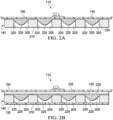
- Figures 2A-2B are schematic section views of an example of the dressing 110, illustrating additional details that may be associated with some embodiments.
- Figure 2A includes an example of the contact layer 140 and an example of the retainer layer 145.
- the cover layer 150 may be disposed over one or more other layers.
- the contact layer 140 can be generally adapted to partially or fully contact a tissue site.
- the contact layer 140 may take many forms, and may have many sizes, shapes, or thicknesses depending on a variety of factors, such as the type of treatment being implemented or the nature and size of a tissue site.
- the size and shape of the contact layer 140 may be adapted to the contours of deep and irregular shaped tissue sites.
- any or all of the surfaces of the contact layer 140 may have projections or an uneven, course, or jagged profile that can induce strains and stresses on a tissue site, which can promote granulation at the tissue site.
- the contact layer 140 may be a manifold.
- a "manifold" in this context generally includes any substance or structure providing a plurality of pathways adapted to collect or distribute fluid across a tissue site under pressure.
- a manifold may be adapted to receive negative pressure from a source and distribute negative pressure through multiple apertures across a tissue site, which may have the effect of collecting fluid from across a tissue site and drawing the fluid toward the source.
- the fluid path may be reversed or a secondary fluid path may be provided to facilitate delivering fluid such as from a source of instillation solution across a tissue site.
- a manifold may be a porous material having interconnected cells or pores.
- cellular foam, open-cell foam, reticulated foam, porous tissue collections, and other porous material such as gauze or felted mat generally include pores, edges, and/or walls adapted to form interconnected fluid channels.
- Liquids, gels, and other foams may also include or be cured to include apertures and fluid pathways.
- perforated, closed-cell foam may be suitable.
- some embodiments of the contact layer 140 may comprise or consist of closed-cell, cross-linked polyolefin foam with holes.
- a manifold may additionally or alternatively comprise projections that form interconnected fluid pathways.
- a manifold may be molded to provide surface projections that define interconnected fluid pathways.
- the average cell size of foam may vary according to needs of a prescribed therapy.
- the contact layer 140 may be foam having pore sizes in a range of 400-600 microns.
- the tensile strength of the contact layer 140 may also vary according to needs of a prescribed therapy. For example, the tensile strength of foam may be increased for instillation of topical treatment solutions.
- the contact layer 140 may be reticulated polyurethane foam such as found in GRANUFOAM TM dressing or V.A.C. VERAFLO TM dressing, both available from KCI of San Antonio, Texas.
- the contact layer 140 may be formed from material that is mechanically or chemically compressed to increase density at ambient pressure.
- the contact layer 140 may comprise or consist of a compressible material, such as a foam that has been compressed.
- Compressed foam may be characterized by a firmness factor that is defined as a ratio of the density of foam in a compressed state to the density of the same foam in an uncompressed state.
- the contact layer 140 may have a firmness factor of about 1 to about 10.
- compressed foam having a density that is five times greater than a density of the same foam in an uncompressed state may be characterized as having a firmness factor of 5.
- the contact layer 140 may comprise or consist of compressed reticulated polyurethane foam, and may have a density of about 0.03 grams per centimeters (g/cm3) in its uncompressed state. If the foam is compressed to have a firmness factor of 5, the foam may be compressed until the density of the foam is about 0.15g/cm3. In some embodiments, the contact layer 140 may comprise or consist of a compressed foam have a thickness between about 4 millimeters to about 15 millimeters, and more specifically, about 8 millimeters at ambient pressure.
- compressed foam exhibits less deformation under negative pressure than a similar uncompressed foam.
- the decrease in deformation may be caused by the increased stiffness as reflected by the firmness factor.
- compressed foam may flatten less than uncompressed foam of similar material.
- the thickness of the contact layer 140 is about 8 millimeters at ambient pressure, the contact layer 140 may have a thickness between about 1 millimeter and about 5 millimeters under therapeutic levels of negative pressure, and, generally, greater than about 3 millimeters.
- the stiffness of compressed foam in the direction parallel to the thickness of the foam may allow the foam to be more compliant or compressible in other directions, such as directions perpendicular to the thickness.
- the contact layer 140 may be either hydrophobic or hydrophilic. In an example in which the contact layer 140 may be hydrophilic, the contact layer 140 may also wick fluid away from a tissue site, while continuing to distribute negative pressure to the tissue site. The wicking properties of the contact layer 140 may draw fluid away from a tissue site by capillary flow or other wicking mechanisms.
- a hydrophilic foam is a polyvinyl alcohol, open-cell foam such as V.A.C. WHITEFOAM TM dressing available from KCI of San Antonio, Texas. Other hydrophilic foams may include those made from polyether. Other foams that may exhibit hydrophilic characteristics include hydrophobic foams that have been treated or coated to provide hydrophilicity.
- the contact layer 140 may further promote granulation at a tissue site when pressure within the sealed therapeutic environment is reduced.
- any or all of the surfaces of the contact layer 140 may have an uneven, coarse, or jagged profile that can induce microstrains and stresses at a tissue site if negative pressure is applied through the contact layer 140.
- the contact layer 140 may be constructed from resorbable or bioresorbable materials.
- resorbable or “bioresorbable” are synonymous and refer to the ability of at least a portion of a material to disintegrate, degrade, or dissolve upon exposure to physiological fluids or processes such that at least a portion of the material may be absorbed or assimilated, for example, at a tissue site or in vivo in a mammalian body. Resorbability or bioresorbability may be exhibited as a result of a chemical process or condition, a physical process or condition, or combinations thereof.
- Suitable bioresorbable materials may include, without limitation, a polymeric blend of polylactic acid (PLA) and polyglycolic acid (PGA).
- the polymeric blend may also include without limitation polycarbonates, polyfumarates, and capralactones.
- the contact layer 140 may further serve as a scaffold for new cell-growth, or a scaffold material may be used in conjunction with the contact layer 140 to promote cell-growth.
- a scaffold is generally a substance or structure used to enhance or promote the growth of cells or formation of tissue, such as a three-dimensional porous structure that provides a template for cell growth.
- Illustrative examples of scaffold materials include calcium phosphate, collagen, PLA/PGA, coral hydroxy apatites, carbonates, or processed allograft materials.
- the contact layer 140 may be formed from thermoplastic elastomers (TPE), such as styrene ethylene butylene styrene (SEBS) copolymers, or thermoplastic polyurethane (TPU).
- TPE thermoplastic elastomers
- SEBS styrene ethylene butylene styrene
- TPU thermoplastic polyurethane
- the contact layer 140 may be formed by combining sheets of TPE or TPU.
- the sheets of TPE or TPU may be bonded, welded, adhered, or otherwise coupled to one another.
- the sheets of TPE or TPU may be welded using radiant heat, radio-frequency welding, or laser welding.
- Supracor, Inc., Hexacor, Ltd., Hexcel Corp., and Econocorp, Inc. may produce suitable TPE or TPU sheets for the formation of the contact layer 140.
- sheets of TPE or TPU having a thickness between about 0.2 mm and about 2.0 mm may be used to form a structure suitable for the contact layer 140.
- the contact layer 140 may be formed from a 3D textile, also referred to as a spacer fabric. Suitable 3D textiles may be produced by Heathcoat Fabrics, Ltd., Baltex, and Mueller Textil Group.
- the contact layer 140 can also be formed from felted foam, polyurethane, silicone, polyvinyl alcohol, and metals, such as copper, tin, silver or other beneficial metals.
- the contact layer 140 may have a substantially uniform thickness.
- a thickness between about 5.0 mm to about 20 mm or about 5.0 mm to about 20 mm may be suitable for some configurations.
- some embodiments of the contact layer 140 may have a thickness of about 8 millimeters.
- the thickness may not be strictly uniform.
- a tolerance of about 2 millimeters may be suitable for some embodiments.
- the contact layer 140 may have one or more holes, cavities, or recesses.
- the holes 205 may extend through the contact layer 140.
- the contact layer 140 has one or more holes 205, which may extend through the contact layer.
- a height or depth of between 1 mm to 40 mm and a width of between 1 mm to 30 mm may be suitable for some examples.
- a depth of about 8 mm may be suitable for some embodiments.
- one or more or all of the holes 205 may be a through-hole that extends through the contact layer 140 from a first surface 210 to a second surface 215.
- the holes 205 may be formed by perforating the contact layer 140 or injection molding.
- the holes 205 may be formed by walls 220 of the contact layer 140.
- one or more of the holes 205 may be a blind hole or other recess, which does not pass completely through the contact layer 140.
- one or more of the holes may extend into the contact layer 140 from the first surface 210 and have a depth that is less than the thickness of the contact layer 140.
- the holes 205 may be defined by walls 220 in the contact layer 140.
- an interior surface of the walls 220 may be generally perpendicular to the first surface 210 and the second surface 215 of the contact layer 140.
- the walls 220 may have a substantially smooth surface between the first surface 210 and the second surface 215 of the contact layer 140.
- the holes 205 may be tapered, and may have conical, pyramidal, or other irregular geometries.
- the holes 205 may be formed so that a central axis of each of the holes 205 is orthogonal to the first surface 210, the second surface 215, or both.
- one or more of the holes 205 may be formed so that the central axis is oblique to the first surface 210, the second surface 215, or both.
- the retainer layer 145 may have one or more projections, protrusions, nodules, or protuberances. As illustrated in the example of Figure 2A , the retainer layer 145 may have projections 225 protruding or configured to protrude into one or more of the holes 205 of the contact layer 140.
- the retainer layer 145 may be made of a foam, such as a reticulated foam. In some examples, the retainer layer 145 may be made of an open-cell foam having relatively larger pore size. An average pore size of between 10 and 80 pores per inch may be suitable for some examples.
- the retainer layer 145 may be flexible, semi-rigid, or rigid.
- the retainer layer 145 may be more flexible or compressible than the contact layer 140. In additional embodiments, the retainer layer 145 may be less dense than the contact layer 140. In certain embodiments, the retainer layer 145 may have a thickness less than the contact layer 140.
- the projections 225 may be formed as an integral portion extending from the retainer layer 145. In other examples, the projections 225 may be coupled to the retainer layer 145.
- the projections 225 may be made of foam, such as reticulated foam. In some embodiments, the projections 225 may protrude from the retainer layer 145 into the holes 205. In some examples, the depth of the projections 225 is less than the depth of the holes 205.
- the projections 225 may have a depth of about 6 millimeters if the holes 205 have a depth of about 8 millimeters. A depth of between 1 mm to 30 mm may be suitable for some embodiments.
- the projections 225 may have a diameter of between 1 to 30 mm (for example, 10 mm). Additionally or alternatively, the projections 225 may have a shape that is complementary to a shape of the holes 205 in the contact layer 140. In non-limiting exemplary embodiments, the projections 225 may have a shape such as a triangle, trapezoid, ellipse, diamond, rectangle, oval, square, circle, octagon, or other suitable shape.
- the projections 225 may at least partially fill some or all of the holes 205. Alternatively, the projections 225 may substantially fill some or all of the holes 205. For example, at least some of the projections 225 can have a tapered end disposed within the holes 205. In some embodiments, there may be a space 230 between the projections 225 and the contact layer 140. In some examples, the projections 225 may have an even or uneven outer surface, such as a ragged outer surface.
- the cover layer 150 may be disposed adjacent to the retainer layer 145, as illustrated in the example of Figure 2A .
- the cover layer 150 may provide a bacterial barrier and protection from physical trauma.
- the cover layer 150 may also be constructed from a material that can reduce evaporative losses and provide a fluid seal between two components or two environments, such as between a therapeutic environment and a local external environment.
- the cover layer 150 may be, for example, an elastomeric film or membrane that can provide a seal adequate to maintain a negative pressure at a tissue site for a given negative-pressure source.
- the cover layer 150 may have a high moisture-vapor transmission rate (MVTR) in some applications.
- MVTR moisture-vapor transmission rate
- the MVTR may be at least 300 g/m2 per twenty-four hours in some embodiments.
- the cover layer 150 may be a polymer drape, such as a polyurethane film, that is permeable to water vapor but impermeable to liquid. Such drapes typically have a thickness in the range of 25-50 microns. For permeable materials, the permeability generally should be low enough that a desired negative pressure may be maintained.
- the contact layer 140 and the retainer layer 145 may be integrated into one component or an integral layer, and may be inseparable.
- the retainer layer 145 may be laminated to the contact layer 140 in some embodiments.
- additional layers or components may be present in the dressing.
- at least one further layer or component may be present between the contact layer 140 and the debriding matrix 135, at least one further layer or component may be present adjacent to a surface of the debriding matrix 135 opposed to a surface of the debriding matrix 135 adjacent to the contact layer 140, and/or at least one further layer or component may be present adjacent to a surface of the contact layer 140 opposed to a surface of contact layer 140 adjacent to the debriding matrix 135.
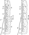
- Figure 2B is a schematic view of another example of the dressing 110 in which the cover layer 150 is not directly coupled to the retainer layer 145.
- a filler layer 235 may be optionally disposed between the retainer layer 145 and the cover layer 150.
- the filler layer 235 may be disposed adjacent to the retainer layer 145 to increase the depth of the dressing 110.
- the debriding matrix 135 can be optionally disposed adjacent to or adhered to a surface of the contact layer 140 in some embodiments.
- the debriding matrix 135 may be in the form of a continuous or non-continuous coating, film, gel, layer and/or sheeting, which may be adhered, fixed, fastened, or joined on the contact layer 140.
- the debriding matrix 135 may be a coating on at least a portion of a surface of the contact layer 140, for example, the debriding matrix 135 may be coated on at least about 10%, at least about 25%, at least about 50%, at least about 75% or at least about 95% of a surface of the contact layer 140.
- the debriding matrix 135 may be a coating on substantially an entire surface of the contact layer 140, for example, the debriding matrix 135 may be coated on at least about 99%, 99.9% or about 100% of a surface of the contact layer 140.
- the debriding matrix 135 may only cover a portion of the holes 205, thus at least a portion of the holes 205 may not be covered by the debriding matrix 135.
- the debriding matrix 135 may be a solid sheet, covering the holes 205 as illustrated in the example of Figure 2B .
- the debriding matrix 135 may at least partially fill at least a portion of the holes 205 or at least partially fill substantially all of the holes 205.
- the debriding matrix 135 may substantially fill at least a portion of the holes 205 or substantially fill substantially all of the holes 205.
- the debriding matrix 135 may be at least partially removable or separable from the contact layer 140. For example, the debriding matrix 135 can be removed from the contact layer 140 and applied directly to a tissue site.
- the thickness of the debriding matrix 135 may vary. A thickness in a range of about 1.0 mm to about 10 mm, about 1.0 mm to about 5.0 mm, or about 1.0 mm to about 3.0 mm may be suitable for some embodiments.
- the debriding matrix 135 may be porous, or may have holes, slits, fenestrations, fluid pathways or other means for fluid flow through the debriding matrix 135.
- the debriding matrix 135 may comprise at least one debriding agent and a polymer.
- the debriding matrix 135 may have a pH of about 2 to about 10 or a lower pH, for example, a pH of about 1.0 to about 6.0 a pH of about 2.0 to about 5.0, or a pH of about 2.5 to about 4.0, wherein a lower pH may further aid in wound healing.
- the debriding agent may be any enzyme capable of debriding a tissue site or wound.
- the term “debriding” or “debridement” refers to the softening, weakening, removal, detachment and/or disruption of tissue and/or cells, such as necrotic tissue, biofilm, slough, eschar, and other debris from a tissue site, for example a wound, which can promote healing and/or reduce risk of infection.
- the debriding agent advantageously may be active (i.e., causing debridement or disruption of tissue) across a broad pH range, for example, a pH of about 2 to about 12, or about 2 to about 10, for example, within a tissue site or wound.
- the debriding agent may be present in varying concentrations and/or United States Pharmacopeia units (USP units) of activity, for example, about 0.25 USP units to about 1,000 USP units, about 0.25 USP units to about 500 USP units, about 0.25 USP units to about 300 USP units or about 30 USP units to about 300 USP units.
- the debriding agent may present in advantageously higher concentrations and/or USP units of activity for enhanced debridement.
- the debriding agent may be selected from the group consisting of papain, urea, streptokinase, streptodornase, trypsin, collagenase, fibrinolysin, deoxyribonuclease (DNase), fibrinolysin with DNase (fibrinolysin/DNase), bromelain, and a combination thereof.
- the polymer may be any suitable organic polymer for immobilizing the debriding agent therein. Additionally, the polymer may be biodegradable. As used herein, the term “biodegradable” refers to a material that is capable of chemically and/or physically deteriorating or breaking down, for example, upon exposure to a tissue site and/or physiological fluids or processes. "Biodegrading” includes tearing, breaking, severing, fracturing, dissolving, dissociating, and the like. Terms such as “soluble,” “dissolvable,” “dissociable,” “tearable,” “breakable,” “severable,” “fracturable,” “disruptable” and the like, may be used and refer to materials that are capable of biodegrading.
- Biodegrading may be exhibited as a result of a chemical process or condition, a physical process or condition, or combinations thereof.
- suitable polymers include, but are not limited to polysaccharides (e.g., citrus fruit pectin, starches, fecula, agar), proteins (e.g., collagen, gelatin, albumin), vegetable gums (e.g., xantham gum, locust bean, guar), and combinations thereof. Additionally or alternatively, the polymer may be bioresorbable.
- the polymer may have a soluble solid composition of at least about 10%, for example, from about 10% to about 90% or 10% to about 70%.
- at least about 10% of the polymer may be soluble in an aqueous solution, for example, having a pH of about 2 to about 10.
- the polymer and/or the debriding matrix 135 may be capable of biodegrading or dissolving during use, for example, when contacted with a tissue site to release the debriding agent, which may debride the tissue site. Complete biodegrading or dissolving of the polymer is not necessary for debriding of the tissue site to occur.
- debriding of the tissue site may occur during one of more of the following: when the debriding matrix 135 initially contacts a tissue site; while the polymer biodegrades or dissolves; once the polymer ceases biodegrading or dissolving; and after the polymer has substantially biodegraded or dissolved.
- the debriding agent and any remaining polymer can be advantageously washed away, for example during instillation therapy at desired time intervals, along with any wound debris.
- the polymer and/or the debriding matrix 135 may dissolve at varying rates, for example, as quickly or as slowly as desired.
- the polymer and/or the debriding matrix 135 may dissolve in a matter of minutes (e.g., 1, 2, 3, 4, 5 minutes, etc.), for example during one therapy cycle, or the polymer and/or the debriding matrix 135 may dissolve over the course of one or more days, for example until an endpoint in therapy.
- minutes e.g. 1, 2, 3, 4, 5 minutes, etc.
- the debriding matrix 135 may further comprise one or more of a drying agent, a thickening agent, and slow release agent in varying amounts.
- drying agents include, but are not limited to silica gel (e.g., silica xerogel, silica gel fibers), magnesium aluminum silicate, calcium oxide, calcium sulfate, a sulfonate, and combinations thereof.
- suitable thickening agents include, but are not limited to glycerol, glycerin, a carbomer, polyethylene glycol and combinations thereof.
- drying and/or thickening agents can aid in disrupting, removing or detaching wound debris by exerting a superficial desiccating and/or denaturing action.
- desiccating and/or denaturing activity along with mechanical action of the dressing can exhibit co-action or synergy in disrupting, removing or detaching wound debris.
- the debriding matrix 135 may further comprise oxidized cellulose.
- oxidized cellulose refers to any material produced by the oxidation of cellulose, for example with dinitrogen tetroxide. Such oxidation converts primary alcohol groups on the saccharide residues to carboxylic acid groups, forming uronic acid residues within the cellulose chain. The oxidation generally does not proceed with complete selectivity, and as a result hydroxyl groups on carbons 2 and 3 are occasionally converted to the keto form. These keto units introduce an alkali-labile link, which at pH 7 or higher initiates the decomposition of the polymer via formation of a lactone and sugar ring cleavage.
- oxidized cellulose is biodegradable and resorbable or bioresorbable under physiological conditions.
- oxidized cellulose present in the debriding matrix 135 may be oxidized regenerated cellulose (ORC), which may be prepared by oxidation of a regenerated cellulose, such as rayon. It has been known that ORC has haemostatic properties. ORC has been available as a haemostatic fabric called SURGICEL ® (Johnson & Johnson Medical, Inc.) since 1950. This product may be produced by the oxidation of a knitted rayon material.
- the debriding matrix 135 may be operatively coupled to the contact layer 140.
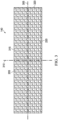
- Figure 3 is a plan view of an example of the contact layer 140, illustrating additional details that may be associated with some embodiments.
- some embodiments of the holes 205 may have a circular cross-section as illustrated in Figure 3 .
- the holes 205 may have an average diameter of greater than about 2.0 mm, greater than about 4.0 mm, greater than about 6.0 mm, greater than about 10 mm or an average diameter between about 5 mm and about 20 mm, and in some embodiments, the average diameter of the holes 205 may be about 10 mm, or in the range of about 5 mm to about 15 mm.
- the contact layer 140 may have a first orientation line 305 and a second orientation line 310 that is perpendicular to the first orientation line 305.
- the first orientation line 305 and the second orientation line 310 may be lines of symmetry through the contact layer 140.
- the contact layer 140 has a generally rectangular shape with longitudinal edges 315 and latitudinal edges 320.
- the first orientation line 305 may be parallel to the longitudinal edges 315.
- the longitudinal edges 315 and the latitudinal edges 320 of the contact layer 140 may not be straight edges.
- one or more of the holes 205 may overlap the longitudinal edges 315 or the latitudinal edges 320, causing the edge to have a non-linear profile, which may reduce the disruption of keratinocyte migration and enhance re-epithelialization while negative pressure is applied to the dressing 110.
- the contact layer 140 may also have a variety of other suitable shapes.
- the contact layer 140 may have a diamond, square, or circular shape.
- the shape of the contact layer 140 may be selected to accommodate the shape or type of a tissue site.
- the contact layer 140 may have an oval or circular shape to accommodate an oval or circular tissue site.
- Figure 4 is a detail view of one of the holes 205 of Figure 3 , illustrating additional details that may be associated with some embodiments.
- one or more of the holes 205 may include a center 405 and a perimeter 410.
- Each of the holes 205 may also be characterized by a shape factor.
- the shape factor may represent an orientation of each of the holes 205 relative to the first orientation line 305 and the second orientation line 310.
- the shape factor is a ratio of 1 ⁇ 2 a maximum dimension that is parallel to the desired direction of contraction to 1 ⁇ 2 a maximum dimension that is perpendicular to the desired direction of contraction.
- the desired direction of contraction in Figure 4 may be parallel to the second orientation line 310, as indicated by vector 415 as the direction of a lateral force.
- a first axis 420 may pass through the center 405 parallel to the first orientation line 305, and a second axis 425 may extend through the center 405 parallel to the second orientation line 310.
- the shape factor of each of the holes 205 may be defined as a ratio of a first line segment 430 on the second axis 425 extending from the center 405 to the perimeter 410, to a second line segment 435 on the first axis 420 extending from the center 405 to the perimeter 410.
- the shape factor would be 1.
- the holes 205 may have other shapes and orientations, for example, oval, hexagonal, elliptical, circular, square, triangular, conical, or amorphous or irregular or a combination thereof and be oriented relative to the first orientation line 305 and the second orientation line 310 so that the shape factor may range from about 0.5 to about 1.10.
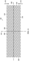
- Figure 5 is a detail view of a portion of the holes 205 of Figure 3 , illustrating additional details that may be associated with some embodiments.
- the holes 205 may be aligned in parallel rows, for example two or more parallel rows, to form an array, as illustrated in the example of Figure 5 .
- an array of the holes 205 may include a first row 505, a second row 510, and a third row 515.
- a width of the walls 220 between the perimeter 410 of two or more of the holes 205 in a row, such as the first row 505 may be about 5 millimeters.
- the center 405 of each of the holes 205 in adjacent rows may be characterized as being offset along the first orientation line 305.
- a strut line 520 passing through the center 405 of each of the holes 205 in adjacent rows may define a strut angle 525 with the first orientation line 305.
- the strut angle 525 may be less than about 90°.
- the strut angle 525 may be between about 30° and about 70°.
- the strut angle 525 may be about 66°.
- a stiffness of the contact layer 140 in a direction parallel to the first orientation line 305 may increase. Increasing the stiffness of the contact layer 140 parallel to the first orientation line 305 may increase the compressibility of the contact layer 140 perpendicular to the first orientation line 305.
- the center 405 of each of the holes 205 in alternating rows may be spaced apart parallel to the second orientation line 310 by a length 530.
- the length 530 may be greater than an effective diameter of the holes 205. In some embodiments, the length 530 may be between about 7 mm and about 25 mm.
- the contact layer 140 may additionally or alternatively be characterized by a void-space percentage, which reflects a ratio of the void space in the first surface 210 created by the holes 205 to the area defined by the perimeter of the contact layer 140 as shown in Figure 1 .
- the void-space percentage can be designed to achieve a desirable balance between handling characteristics and flexibility. For example, increasing the void-space percentage may increase the contraction characteristics of the holes 205, and may also decrease the handling characteristics of the contact layer 140.
- a void-space percentage between about 40% and about 75% may be suitable for some embodiments. For example, some embodiments may have a void-space percentage of about 55%.
- the holes 205 may have an effective diameter between about 3 millimeters and about 20 millimeters.
- An effective diameter of a non-circular area is a diameter of a circular area having the same surface area as the non-circular area.
- one or more of the holes 205 have a non-circular cross-section with an effective diameter of about 3.5 mm.
- the holes 205 may have an effective diameter between about 5 mm and about 20 mm.
- the holes 205 are not formed by a foaming process, and can be distinguished from pores or cells of material forming the contact layer 140.
- a single pore or cell of the material is generally not large enough to extend completely through the contact layer 140.
- An effective diameter of the holes 205 may be an order of magnitude larger than the effective diameter of the pores or cells of a material forming the contact layer 140.
- the effective diameter of the holes may be larger than about 1 mm, while the material of the contact layer 140 may be foam having a pore size less than about 600 microns.
- the holes 205 may be formed during molding of the contact layer 140. In other embodiments, the holes 205 may be formed by cutting, melting, drilling, or vaporizing the contact layer 140 after the contact layer 140 is formed. For example, a through-hole may be formed by reaming, drilling, or milling a hole completely through the contact layer 140. Additionally or alternatively, the holes 205 may be laser-cut into the contact layer 140.
- formation of the holes 205 may thermoform the material of the contact layer 140, causing the interior surface of the holes 205 to be nonporous. For example, laser-cutting the holes 205 into the contact layer 140 may plastically deform the material of the contact layer 140, closing any pores on the interior surfaces of the holes 205.
- a smooth interior surface of the holes 205 may be formed by a applying or coating a smooth material to the holes 205. In some embodiments, a smooth interior surface may limit or otherwise inhibit ingrowth of tissue into the contact layer 140 through the holes 205.
- the shape of the holes 205 may vary in different embodiments of the contact layer 140 to vary the concentration of stresses.
- Figure 6 is a plan view of another embodiment of the contact layer 140, illustrating additional details in which the holes 205 have a hexagonal cross-section, which can cause a lateral force 415.
- Figure 7 is a plan view of another example of the contact layer 140, illustrating additional details in which the holes 205 have an elliptical or oval cross-section and a lateral force 415.
- Figure 8 is a plan view of another example of the contact layer 140, illustrating additional details in which the holes 205 have a triangular cross-section and a lateral force 415.
- a negative-pressure supply such as the negative-pressure source 105, may be a reservoir of air at a negative pressure, or may be a manual or electrically-powered device, such as a vacuum pump, a suction pump, a wall suction port available at many healthcare facilities, or a micro-pump, for example.
- Negative pressure generally refers to a pressure less than a local ambient pressure, such as the ambient pressure in a local environment external to a sealed therapeutic environment. In many cases, the local ambient pressure may also be the atmospheric pressure at which a tissue site is located. Alternatively, the pressure may be less than a hydrostatic pressure associated with tissue at the tissue site. Unless otherwise indicated, values of pressure stated herein are gauge pressures.
- references to increases in negative pressure typically refer to a decrease in absolute pressure, while decreases in negative pressure typically refer to an increase in absolute pressure. While the amount and nature of negative pressure applied to a tissue site may vary according to therapeutic requirements, the pressure is generally a low vacuum, also commonly referred to as a rough vacuum, between -5 mm Hg (-667 Pa) and -500 mm Hg (-66.7 kPa). Common therapeutic ranges are between -50 mm Hg (-6.7 kPa) and -300 mm Hg (-39.9 kPa).
- the container 115 is representative of a container, canister, pouch, or other storage component, which can be used to manage exudates and other fluids withdrawn from a tissue site.
- a rigid container may be preferred or required for collecting, storing, and disposing of fluids.
- fluids may be properly disposed of without rigid container storage, and a re-usable container could reduce waste and costs associated with negative-pressure therapy.
- a controller such as the controller 120, may be a microprocessor or computer programmed to operate one or more components of the therapy system 100, such as the negative-pressure source 105.
- the controller 120 may be a microcontroller, which generally comprises an integrated circuit containing a processor core and a memory programmed to directly or indirectly control one or more operating parameters of the therapy system 100. Operating parameters may include the power applied to the negative-pressure source 105, the pressure generated by the negative-pressure source 105, or the pressure distributed to the contact layer 140, for example.
- the controller 120 may be configured to receive one or more input signals, such as a feedback signal, and programmed to modify one or more operating parameters based on the input signals.
- Sensors such as the first sensor 125 or the second sensor 130, are generally known in the art as any apparatus operable to detect or measure a physical phenomenon or property, and generally provide a signal indicative of the phenomenon or property that is detected or measured.
- the first sensor 125 and the second sensor 130 may be configured to measure one or more operating parameters of the therapy system 100.
- the first sensor 125 may be a transducer configured to measure pressure in a pneumatic pathway and convert the measurement to a signal indicative of the pressure measured.
- the first sensor 125 may be a piezoresistive strain gauge.
- the second sensor 130 may optionally measure operating parameters of the negative-pressure source 105, such as the voltage or current, in some embodiments.
- the signals from the first sensor 125 and the second sensor 130 are suitable as an input signal to the controller 120, but some signal conditioning may be appropriate in some embodiments.
- the signal may need to be filtered or amplified before it can be processed by the controller 120.
- the signal is an electrical signal, but may be represented in other forms, such as an optical signal.
- An attachment device may be used to attach the cover layer 150 to an attachment surface, such as undamaged epidermis, a gasket, or another cover.
- the attachment device may take many forms.
- an attachment device may be a medically-acceptable, pressure-sensitive adhesive configured to the cover layer 150 to epidermis around a tissue site.
- the cover layer 150 may be coated with an adhesive, such as an acrylic adhesive, which may have a coating weight between 25-65 grams per square meter (g.s.m.). Thicker adhesives, or combinations of adhesives, may be applied in some embodiments to improve the seal and reduce leaks.
- Other example embodiments of an attachment device may include a double-sided tape, paste, hydrocolloid, hydrogel, silicone gel, or organogel.
- the solution source 165 may also be representative of a container, canister, pouch, bag, or other storage component, which can provide a solution for instillation therapy.
- Compositions of solutions may vary according to a prescribed therapy, but examples of solutions that may be suitable for some prescriptions include hypochlorite-based solutions, silver nitrate (0.5%), sulfur-based solutions, biguanides, cationic solutions, and isotonic solutions.
- a method for debriding a tissue site may comprise positioning a dressing, such as the dressing 110, adjacent to a tissue site.
- the contact layer 140 may be positioned on or over the tissue site.
- the debriding matrix may be positioned on the tissue site.
- the debriding matrix 135 and the contact layer 140 may be positioned separately or together, such that the debriding matrix 135 may be adjacent to the tissue site and the contact layer 140 may be adjacent to the debriding matrix.
- a separate debriding matrix or a debriding matrix which has been separated from a contact layer may be positioned adjacent to the tissue site, followed by positioning of the contact layer adjacent to the debriding matrix.
- the dressing 110 with the debriding matrix 135 operatively coupled to the contact layer 140 may be positioned adjacent to the tissue site.
- Negative pressure may be supplied to the dressing 110 for treatment of the tissue site.
- negative pressure may be delivered to the tissue site through the contact layer 140 or through the contact layer 140 and the debriding matrix 135.
- the debriding matrix 135 may be porous, or may have holes, slits, fenestrations or other fluid pathways through which fluid may be delivered to the tissue site.
- the debriding matrix 135 may be at least partially biodegraded or dissolved by one or more of exudate, instillation solution, and negative pressure, which can create fluid pathways. At least a portion of debriding matrix 135 may biodegrade or dissolve and continue to biodegrade or dissolve throughout treatment.
- substantially all of the debriding matrix may biodegrade or dissolve during treatment.
- One or more debriding agents may contact the tissue site and advantageously debride, for example, through enzymatic debridement, at least a portion of the tissue site including debris present therein.
- debridement may only comprise enzymatic debridement.
- time between dressing changes can be increased, for example, by controlling the rate at which the debriding matrix 135 biodegrades or dissolves.
- the dressing may remain adjacent to a tissue site for greater than 1 day, greater than 3, greater than 5 days, or greater than 7 days, before a dressing change.
- the dressing may remain adjacent to a tissue for about 1 to 7 days or about 3 to 5 days.
- use of instillation therapy during these intervals between dressing changes can advantageously remove at least a portion of a debriding agent from the tissue site so that toxicity to the tissue site can be minimized.
- FIG 9A is a schematic view of the dressing 110 of Figure 2A , illustrating additional details that may be associated with some embodiments of using the dressing 110 to treat a tissue site 900.
- the tissue site 900 may include debris.
- the debris may comprise one or more of biofilms, necrotic tissue, lacerated tissue, devitalized tissue, contaminated tissue, damaged tissue, infected tissue, exudate, highly viscous exudate, and fibrinous slough.
- the debris may cover all or a portion of the tissue site.
- biofilms can comprise a microbial infection that can cover the tissue site and impair healing of the tissue site. Biofilms can also lower the effectiveness of topical antibacterial treatments by preventing the topical treatments from reaching the tissue site.
- necrotic tissue may be dead tissue resulting from infection, toxins, or trauma that caused the tissue to die faster than the tissue can be removed by the normal body processes that regulate the removal of dead tissue.
- necrotic tissue may be in the form of slough, which may include viscous liquid mass of tissue.
- slough is produced by bacterial and fungal infections that stimulate an inflammatory response in the tissue. Slough may be a creamy yellow color and may also be referred to as pus.
- Necrotic tissue may also include eschar. Eschar may be a portion of necrotic tissue that has become dehydrated and hardened. Eschar may be the result of a burn injury, gangrene, ulcers, fungal infections, spider bites, or anthrax, and can be difficult to remove.
- the dressing 110 may be placed in or on a tissue site, and the cover layer 150 may be sealed to an attachment surface, such as epidermis peripheral to a tissue site.
- the geometry and dimensions of the retainer layer 145, the filler layer 235, or the cover layer 150 may vary to suit a particular application or anatomy.
- the geometry or dimensions of the cover layer 150 may be adapted to provide an effective and reliable seal at or around a tissue site.
- the dimensions may be modified to increase the surface area for the dressing 110 to enhance the movement and proliferation of epithelial cells at or around a tissue site and reduce the likelihood of granulation tissue ingrowth.
- the dressing 110 optionally may be customized prior to positioning adjacent to the tissue site.
- Customizing may include cutting and/or sizing the dressing 110 as needed for use with the tissue site.
- the contact layer 140 and the retaining layer 145 may be customized either separately or together as needed and then positioned on the tissue site.
- the filler layer 235 optionally may be positioned over or adjacent to the retainer layer 145 such that the filler layer 235 may be disposed between the cover layer 150 and the retainer layer 145.
- a negative-pressure source can be fluidly coupled to a sealed environment through the cover layer 150 and the tissue site.
- a fluid conductor 905 may have a first end coupled to the filler layer 235 or the retainer layer 145 and a second end coupled to the negative-pressure source 105.
- the negative-pressure source can reduce the pressure in the sealed environment.
- negative pressure may be supplied to the sealed environment until the pressure in the sealed environment reaches a predetermined therapy pressure.
- Negative pressure may be supplied to the sealed environment for any suitable amount of time, for example, at least about 10 minutes, at least about 30 minutes or less than about 60 minutes.
- the therapy period may be longer or shorter as needed to supply appropriate negative-pressure therapy to a tissue site.
- Figure 9B illustrates the dressing 110 of Figure 9A with negative pressure applied.
- the contact layer 140 can contract under negative pressure.
- the space 230 may decrease or be eliminated, and slough or other tissue can be drawn into the holes 205.
- the contact layer 140 may be configured to substantially retain its shape under negative pressure, which can encourage tissue to be drawn into the holes or recesses.
- the contact layer 140 may have a density or a thickness greater than that of the retainer layer 145.
- portions of the tissue site 900 are drawn into contact with the projections 225, which can debride or remove the slough or other tissues in the holes 205 of the contact layer 140.
- the retainer layer 145, the projections 225, or both may be drawn down under negative pressure.
- the projections 225 may be drawn into contact with tissue drawn up through the holes 205 in some embodiments of the contact layer 140.
- the projections 225 may be formed to a predetermined size, a predetermined shape, or a predetermined firmness factor, which can depend on prescribed treatment factors.
- treatment factors may include uniformity or aggressiveness of contact with tissue.
- the size of the projections 225 may be selected based on the firmness factor and shape of the projections 225, magnitude of negative pressure in the sealed environment, the dimensions of the holes 205, the firmness factor of the retainer layer 145, and the shape and size of the tissue drawn into the holes 205 to provide a debriding force for the tissue drawn into the holes 205.
- the projections 225 may have a depth, size, shape, and thickness selected to create a debriding force applied to tissues drawn into the holes 205 under a negative pressure.
- the firmness factor of the projections 225 and the retainer layer 145 can be selected to control the depth of the projections 225 into the holes 205 under a negative pressure.
- the projections 225 may have a firmness factor equal to or less than that of the contact layer 140.
- the projection 225 may be configured to be exposed to the tissue or nodules inside the holes 205 and may be used as a cutting edge to disrupt the tissue or nodules when under negative pressure.
- the projection 225 may contact at least a portion of the outer surface of the holes 205 to debride in the negative pressure therapy.
- the dressing 110 is under negative pressure, some portions of the large pores of the retainer layer 145, especially of the projections 225, may be compressed against the macro-deformation of a tissue site, such as a wound bed. If the negative pressure is held on a tissue site, the large pores of the retainer layer 145 may accept slough and allow macro-deformation to form. The large pore size of the retainer layer 145 may also help apply micro-strain to the top portions of the macro-deformation on a tissue site.
- the therapy system 100 may vent the environment.
- the therapy system 100 may fluidly couple the sealed environment to the atmosphere, allowing the sealed environment to return to ambient pressure.
- the therapy system 100 may vent the sealed environment for about 1 minute, for example, by maintaining the sealed environment at ambient pressure.
- the therapy system 100 may vent the sealed environment for longer or shorter periods.
- the negative-pressure source 105 may begin another negative-pressure therapy cycle. In some embodiments, negative pressure may be supplied to the sealed environment for about 1 minute and the sealed environment may be vented for about 1 minute.
- negative-pressure treatment may be provided cyclically, alternately applying and venting negative pressure in the sealed environment, for example, via the therapy system 100.
- Figure 10 is a view of the contact layer 140 contracting under negative pressure, illustrating additional details that may be associated some embodiments of the dressing 110.
- the first orientation line 305 and the second orientation line 310 may be used to orient the desired directions of contraction of the contact layer 140.
- the desired direction of contraction may be parallel to the second orientation line 310 and perpendicular to the first orientation line 305.
- the desired direction of contraction may be parallel to the first orientation line 305 and perpendicular to the second orientation line 310.
- the desired direction of contraction may be at an oblique angle to both the first orientation line 305 and the second orientation line 310.
- the contact layer 140 may not have a desired direction of contraction.
- the holes 205 may contract, which can disrupt the debris.
- the edges of the holes 205 may form cutting edges that can disrupt the debris.
- the cutting edges may be defined by the perimeter 410 of each of the holes 205.
- negative pressure may be supplied for a few seconds and then vented for a few seconds, causing a pulsation of negative pressure in a sealed environment.
- the pulsation of the negative pressure can pulse the nodules, which can cause further disruption of the debris.
- Such contraction of the contact layer 140 and holes 205 in combination with the action of the one or more debriding agents at the tissue site can not only advantageously allow for increased debridement at the tissue site but also advantageously result in co-action or synergy in debriding the tissue site and debris.
- Contraction can refer to both vertical contraction and lateral contraction.
- the material, the void space percentage, the perforation shape factor, the firmness factor, the dimensions of the holes 205, and the strut angle may influence or control the direction of contraction.
- one or more of the void space percentage, the perforation shape factor, or the strut angle can cause the contact layer 140 to contract along the second orientation line 310 perpendicular to the first orientation line 305 as shown in Figure 6 . If the contact layer 140 is positioned on a tissue site, the contact layer 140 may contract in the direction of the lateral force 415 toward the first orientation line 305.
- the holes 205 may be circular, the strut angle may be approximately 37°, the void space percentage may be about 54%, the firmness factor may be about 5, the shape factor may be about 1, and the diameter may be about 5 millimeters. If the contact layer 140 is subjected to a negative pressure of about -125 mmHg, the contact layer 140 can assert a lateral force 415 in the direction of approximately 11.9 N. If the diameter of the holes 205 is increased to about 20 millimeters, the void space percentage changed to about 52%, the strut angle changed to about 52°, and the perforation shape factor and the firmness factor remain the same, the lateral force can be decreased to about 6.5 N.
- dimensions of the holes 205 may be selected to permit flow of particulates through the holes 205.
- the effective diameter of the holes 205 may be selected based on an anticipated size of solubilized debris to be lifted from a tissue site. Dimensions may also be selected to allow larger debris and block smaller debris. In some examples, some or all of the debris may be drawn through the holes 205 and collected in the container 115.
- the size of the holes 205 may differ on successive applications of the dressing 110. For example, the dimensions of the holes 205 may be decreased as the size of the debris decreases. Sequentially decreasing size of the holes 205 may also aid in fine tuning a level of tissue disruption to the debris during the treatment of a tissue site.
- the dimensions of the holes 205 can also influence fluid movement in the contact layer 140 and the dressing 110.
- the contact layer 140 can channel fluid in the dressing 110 toward the holes 205 to aid in the disruption of the debris on the tissue site.
- Variation of the dimensions of the holes 205 can vary how fluid is moved through the dressing 110 with respect to both the removal of fluid and the application of negative pressure.
- stresses on the debris may be focused at the vertices of the holes 205.
- Suitable characteristics of the contact layer 140 of Figure 7 may include a strut angle of approximately 66°, a void space percentage of about 55%, a firmness factor of about 5, a perforation shape factor of about 1.07, and an effective diameter of about 5 millimeters. If the contact layer 140 of Figure 7 is subjected to a negative pressure of about -125 mmHg, the lateral force 415 of the contact layer 140 may be about 13.3 N. If the effective diameter of the holes 205 is increased to 10 millimeters, the lateral force 415 may be decreased to about 7.5 N.
- the debris can be removed from a surface of the tissue site during dressing changes.
- the contact layer 140 may be removed and disrupted debris may be removed by wiping away the debris.
- the contact layer 140 may disrupt the debris so that the debris can be removed by negative pressure.
- instillation therapy may be combined with negative-pressure therapy.
- the solution source 165 may be fluidly coupled to the contact layer 140 in some embodiments. Following a period of negative-pressure therapy, the therapy system 100 may operate the solution source 165 to provide fluid to the sealed environment. In some embodiments, the solution source 165 may provide fluid while the sealed environment is vented. In other embodiments, the sealed environment may not be vented, and the negative pressure in the sealed environment may draw instillation fluid from the solution source 165 into the sealed environment.
- the fluid removed may also comprise one or more of at least a portion of one or more debriding agents, at least a portion of the polymer and at least a portion of any further components, such as thickening agents and/or drying agents, of the debriding matrix.
- the solution source 165 may provide a volume of fluid to the sealed environment.
- the volume of fluid may be the same as a volume of the sealed environment. In other embodiments, the volume of fluid may be smaller or larger than the sealed environment. Instilling solution into the sealed environment can increase pressure above ambient pressure, for example to between about 0 mmHg and about 15 mmHg and, more specifically, about 5 mmHg.
- fluid provided by the solution source 165 may remain in the sealed environment for a prescribed dwell time. In some embodiments, the dwell time may be about 5 minutes. In other embodiments, the dwell time may be longer or shorter as prescribed. For example, the dwell time may be zero.
- the negative-pressure source 105 may be operated to draw the instillation fluid into the container 115, completing a cycle of therapy.
- negative pressure may also be supplied to the sealed environment, starting another cycle of therapy.
- the methods described herein may be used in conjunction with other tissue removal and debridement techniques.
- further mechanical and/or enzymatic debridement process may be used to remove further portions of the debris, for example, before positioning of the dressing 110 and/or after supplying negative pressure and/or fluid to the tissue site.
- sharp debridement may also be used as necessary for removal at least a portion of the debris, for example, before positioning of the dressing 110 and/or after supplying negative pressure and/or fluid to the tissue site.
- Sharp debridement may include, but is not limited to the use of a scalpel, scissor or other sharp instrument in debriding a tissue site.
- the therapy system 100 can provide mechanical movement and debriding agents in combination with negative pressure, instillation solution, or both, to solubilize, debride, and/or remove the debris.
- mechanical debridement and enzymatic debridement may be provided in combination.
- cyclical application of instillation therapy and negative pressure therapy may cause the contact layer 140 to float and change position relative to the debris.
- negative pressure may be applied to the sealed environment during a negative-pressure therapy cycle.
- instillation fluid may be supplied during the instillation therapy cycle.
- the instillation fluid may cause the contact layer 140 to float relative to the debris.
- the position change may cause the contact layer 140 to engage a slightly different portion of the debris during the next negative-pressure therapy cycle, aiding disruption of the debris.
- the dressing 110 may allow more thorough slough removal.
- the dressing 110 may allow improved slough removal through improved contact of the dressing 110 with a tissue site, e.g., a wound bed, under negative pressure.
- the dressing 110 may provide a solution to de-sloughing the tops of macro-deformation formed on the wound bed during negative pressure therapy.
- the retainer layer 145 may be omitted in some embodiments.
- the holes 205 may be recesses in the contact layer 140, and tissue can be drawn into the recesses under negative pressure. Projections can be disposed within recesses in some examples.
Landscapes
- Health & Medical Sciences (AREA)
- Heart & Thoracic Surgery (AREA)
- Life Sciences & Earth Sciences (AREA)
- Veterinary Medicine (AREA)
- Engineering & Computer Science (AREA)
- Biomedical Technology (AREA)
- Animal Behavior & Ethology (AREA)
- General Health & Medical Sciences (AREA)
- Public Health (AREA)
- Vascular Medicine (AREA)
- Surgery (AREA)
- Nuclear Medicine, Radiotherapy & Molecular Imaging (AREA)
- Medical Informatics (AREA)
- Molecular Biology (AREA)
- Anesthesiology (AREA)
- Hematology (AREA)
- Media Introduction/Drainage Providing Device (AREA)
Claims (13)
- Pansement pour le traitement d'un site tissulaire avec une pression négative, avant l'application d'une pression réduite, le pansement comprenant :une couche de contact (140) comprenant un premier collecteur ayant une pluralité de trous (205) à travers le premier collecteur ; etune couche de retenue (145) comprenant un second collecteur ayant une pluralité de saillies (225), au moins l'une des saillies (225) faisant saillie, sans application de pression réduite, dans au moins l'un de la pluralité de trous (205).
- Pansement selon la revendication 1, dans lequel le second collecteur est plus compressible que le premier collecteur.
- Pansement selon la revendication 1 ou 2, dans lequel la pluralité de saillies (225) sont complémentaires de la pluralité de trous (205).
- Pansement selon la revendication 1, 2 ou 3, dans lequel au moins certaines de la pluralité de saillies (225) ont une extrémité effilée disposée à l'intérieur de la pluralité de trous (205).
- Pansement selon la revendication 1 ou l'une quelconque des revendications 2 à 4, dans lequel le premier collecteur ou le second collecteur comprend une mousse à cellules ouvertes.
- Pansement selon la revendication 1 ou l'une quelconque des revendications 2 à 5, dans lequel une ou plusieurs de la pluralité de saillies (225) ont une surface externe à structure.
- Pansement selon la revendication 1 ou l'une quelconque des revendications 2 à 6, dans lequel au moins l'un de la pluralité de trous (205) a un diamètre compris entre 1 et 30 mm et une hauteur comprise entre 1 mm et 30 mm.
- Pansement selon la revendication 1 ou l'une quelconque des revendications 2 à 7, dans lequel la couche de retenue (145) comprend une mousse ayant une taille moyenne de pore comprise entre 10 et 80 pores par pouce.
- Pansement selon la revendication 1 ou l'une quelconque des revendications 2 à 8, dans lequel la couche de contact (140) et la couche de retenue (145) sont reliées en tant que couche intégrale.
- Pansement selon la revendication 1 ou l'une quelconque des revendications 2 à 9, dans lequel le pansement comprend en outre une couche de couverture (150) conçue pour être positionnée adjacente à la couche de retenue (145).
- Pansement selon la revendication 1 ou l'une quelconque des revendications 2 à 10, dans lequel la pluralité de trous (205) sont conçus pour s'affaisser d'une position détendue à une position contractée en réponse à une pression négative.
- Pansement selon la revendication 1 ou l'une quelconque des revendications 2 à 11, dans lequel le pansement est conçu pour être accouplé fluidiquement à une source de pression négative (105).
- Pansement selon la revendication 1 ou l'une quelconque des revendications 2 à 12, dans lequel le pansement est conçu pour être accouplé fluidiquement à une source de fluide (165).
Applications Claiming Priority (2)
| Application Number | Priority Date | Filing Date | Title |
|---|---|---|---|
| US201862757503P | 2018-11-08 | 2018-11-08 | |
| PCT/US2019/060479 WO2020097467A1 (fr) | 2018-11-08 | 2019-11-08 | Pansement avec couche en saillie permettant le nettoyage de macro-déformations de lit de plaie |
Publications (2)
| Publication Number | Publication Date |
|---|---|
| EP3876886A1 EP3876886A1 (fr) | 2021-09-15 |
| EP3876886B1 true EP3876886B1 (fr) | 2023-09-27 |
Family
ID=69160137
Family Applications (1)
| Application Number | Title | Priority Date | Filing Date |
|---|---|---|---|
| EP19836102.4A Active EP3876886B1 (fr) | 2018-11-08 | 2019-11-08 | Pansement avec couche en saillie permettant le nettoyage de macro-déformations de lit de plaie |
Country Status (5)
| Country | Link |
|---|---|
| US (2) | US20200146896A1 (fr) |
| EP (1) | EP3876886B1 (fr) |
| JP (1) | JP2022506830A (fr) |
| CN (2) | CN117838434A (fr) |
| WO (1) | WO2020097467A1 (fr) |
Families Citing this family (12)
| Publication number | Priority date | Publication date | Assignee | Title |
|---|---|---|---|---|
| GB0808376D0 (en) | 2008-05-08 | 2008-06-18 | Bristol Myers Squibb Co | Wound dressing |
| GB201020236D0 (en) | 2010-11-30 | 2011-01-12 | Convatec Technologies Inc | A composition for detecting biofilms on viable tissues |
| US9526816B2 (en) | 2010-12-08 | 2016-12-27 | Convatec Technologies Inc. | Wound exudate monitor accessory |
| WO2012078781A1 (fr) | 2010-12-08 | 2012-06-14 | Convatec Technologies Inc. | Système intégré pour évaluer des exsudats de plaie |
| GB2497406A (en) | 2011-11-29 | 2013-06-12 | Webtec Converting Llc | Dressing with a perforated binder layer |
| KR20150099776A (ko) | 2012-12-20 | 2015-09-01 | 컨바텍 테크놀러지스 인크 | 화학적 개질된 셀룰로스 섬유의 처리 |
| EP3481360B1 (fr) | 2016-07-08 | 2022-03-09 | ConvaTec Technologies Inc. | Détecteur de l'écoulement d'un liquide. |
| WO2018009873A1 (fr) | 2016-07-08 | 2018-01-11 | Convatec Technologies Inc. | Appareil de collecte de fluide |
| ES2882336T3 (es) | 2016-07-08 | 2021-12-01 | Convatec Technologies Inc | Sistema flexible de presión negativa |
| US11331221B2 (en) | 2019-12-27 | 2022-05-17 | Convatec Limited | Negative pressure wound dressing |
| US11771819B2 (en) | 2019-12-27 | 2023-10-03 | Convatec Limited | Low profile filter devices suitable for use in negative pressure wound therapy systems |
| EP4228575A1 (fr) * | 2020-12-01 | 2023-08-23 | KCI Manufacturing Unlimited Company | Collecteur de pansement contractable avec croissance tissulaire réduite |
Family Cites Families (8)
| Publication number | Priority date | Publication date | Assignee | Title |
|---|---|---|---|---|
| US8529528B2 (en) * | 2008-12-24 | 2013-09-10 | Kci Licensing, Inc. | Reduced-pressure wound treatment systems and methods employing microstrain-inducing manifolds |
| ES1070675Y (es) * | 2009-05-20 | 2010-01-14 | Canada Juan Marquez | Aposito de vacio mejorado aplicable como tratamiento de compresion postoperatoria |
| US9358158B2 (en) * | 2010-03-16 | 2016-06-07 | Kci Licensing, Inc. | Patterned neo-epithelialization dressings, systems, and methods |
| WO2012078561A2 (fr) * | 2010-12-07 | 2012-06-14 | Kci Licensing, Inc. | Drap ayant des projections induisant des micro-contraintes pour le traitement d'un site de plaie |
| EP2758086B1 (fr) * | 2011-09-20 | 2018-05-23 | KCI Licensing, Inc. | Systèmes et procédés de traitement de tissu ayant un matériau à déformation macroscopique activé par un stimulus non tactile |
| EP3005997A1 (fr) * | 2011-12-16 | 2016-04-13 | KCI Licensing, Inc. | Champs opératoires médicaux libérables |
| JP6749248B2 (ja) * | 2014-05-09 | 2020-09-02 | ケーシーアイ ライセンシング インコーポレイテッド | 線形組織部位用の収縮層を備えたドレッシング |
| EP3354241B1 (fr) * | 2014-05-09 | 2020-12-30 | 3M Innovative Properties Company | Pansement à effet perturbateur destiné à être utilisé en pression négative et avec instillation de fluide |
-
2019
- 2019-11-08 WO PCT/US2019/060479 patent/WO2020097467A1/fr unknown
- 2019-11-08 CN CN202311614633.7A patent/CN117838434A/zh active Pending
- 2019-11-08 US US16/678,292 patent/US20200146896A1/en active Granted
- 2019-11-08 CN CN201980081696.6A patent/CN113543755B/zh active Active
- 2019-11-08 JP JP2021524439A patent/JP2022506830A/ja active Pending
- 2019-11-08 EP EP19836102.4A patent/EP3876886B1/fr active Active
-
2023
- 2023-12-12 US US18/537,471 patent/US20240099898A1/en active Pending
Also Published As
| Publication number | Publication date |
|---|---|
| WO2020097467A1 (fr) | 2020-05-14 |
| US20240099898A1 (en) | 2024-03-28 |
| CN113543755B (zh) | 2023-12-15 |
| CN117838434A (zh) | 2024-04-09 |
| CN113543755A (zh) | 2021-10-22 |
| JP2022506830A (ja) | 2022-01-17 |
| US20200146896A1 (en) | 2020-05-14 |
| EP3876886A1 (fr) | 2021-09-15 |
Similar Documents
| Publication | Publication Date | Title |
|---|---|---|
| EP3876886B1 (fr) | Pansement avec couche en saillie permettant le nettoyage de macro-déformations de lit de plaie | |
| US11850124B2 (en) | Debridement wound dressings and systems and methods using the same | |
| AU2021232704B2 (en) | Debriding dressing for use with negative pressure and fluid instillation | |
| AU2020203649B2 (en) | Disruptive dressing for use with negative pressure and fluid instillation | |
| EP3876885B1 (fr) | Pansement à support semi-rigide destiné à augmenter la rupture au moyen d'un pansement perforé et d'un traitement de plaie par pression négative | |
| US11752039B2 (en) | Dressings for reduced tissue ingrowth | |
| EP3294158B1 (fr) | Débridement de blessure par irrigation à microbulles activées par ultrasons | |
| US20230000687A1 (en) | Tissue interface for negative-pressure and instillation therapy | |
| US20230000688A1 (en) | Tissue interface for negative pressure and instillation therapy | |
| US20220249291A1 (en) | Antimicrobial/antibacterial disruptive dressing for use with negative pressure and fluid instillation | |
| JP2023536800A (ja) | 組織デブリドマン用の組織インタフェース | |
| WO2021171161A1 (fr) | Pansement pour cavité de plaie permettant le nettoyage de la plaie | |
| WO2021094972A1 (fr) | Dispositifs, systèmes et procédés d'administration d'un matériau fluide destiné à être utilisé en tant que pansement tissulaire | |
| CN116367800A (zh) | 低向内生长组织界面 |
Legal Events
| Date | Code | Title | Description |
|---|---|---|---|
| STAA | Information on the status of an ep patent application or granted ep patent |
Free format text: STATUS: UNKNOWN |
|
| STAA | Information on the status of an ep patent application or granted ep patent |
Free format text: STATUS: THE INTERNATIONAL PUBLICATION HAS BEEN MADE |
|
| PUAI | Public reference made under article 153(3) epc to a published international application that has entered the european phase |
Free format text: ORIGINAL CODE: 0009012 |
|
| STAA | Information on the status of an ep patent application or granted ep patent |
Free format text: STATUS: REQUEST FOR EXAMINATION WAS MADE |
|
| 17P | Request for examination filed |
Effective date: 20210524 |
|
| AK | Designated contracting states |
Kind code of ref document: A1 Designated state(s): AL AT BE BG CH CY CZ DE DK EE ES FI FR GB GR HR HU IE IS IT LI LT LU LV MC MK MT NL NO PL PT RO RS SE SI SK SM TR |
|
| DAV | Request for validation of the european patent (deleted) | ||
| DAX | Request for extension of the european patent (deleted) | ||
| REG | Reference to a national code |
Ref country code: DE Ref legal event code: R079 Ref document number: 602019038356 Country of ref document: DE Free format text: PREVIOUS MAIN CLASS: A61F0013000000 Ipc: A61B0017320000 Ref country code: DE Ref legal event code: R079 |
|
| GRAP | Despatch of communication of intention to grant a patent |
Free format text: ORIGINAL CODE: EPIDOSNIGR1 |
|
| STAA | Information on the status of an ep patent application or granted ep patent |
Free format text: STATUS: GRANT OF PATENT IS INTENDED |
|
| RIC1 | Information provided on ipc code assigned before grant |
Ipc: A61M 1/00 20060101ALI20230601BHEP Ipc: A61F 13/02 20060101ALI20230601BHEP Ipc: A61F 13/00 20060101ALI20230601BHEP Ipc: A61B 17/00 20060101ALI20230601BHEP Ipc: A61B 17/32 20060101AFI20230601BHEP |
|
| INTG | Intention to grant announced |
Effective date: 20230621 |
|
| RIN1 | Information on inventor provided before grant (corrected) |
Inventor name: INGRAM, SHANNON C. Inventor name: CARROLL, CHRISTOPHER ALLEN Inventor name: RICE, JUSTIN |
|
| GRAS | Grant fee paid |
Free format text: ORIGINAL CODE: EPIDOSNIGR3 |
|
| GRAA | (expected) grant |
Free format text: ORIGINAL CODE: 0009210 |
|
| STAA | Information on the status of an ep patent application or granted ep patent |
Free format text: STATUS: THE PATENT HAS BEEN GRANTED |
|
| AK | Designated contracting states |
Kind code of ref document: B1 Designated state(s): AL AT BE BG CH CY CZ DE DK EE ES FI FR GB GR HR HU IE IS IT LI LT LU LV MC MK MT NL NO PL PT RO RS SE SI SK SM TR |
|
| RAP1 | Party data changed (applicant data changed or rights of an application transferred) |
Owner name: 3M INNOVATIVE PROPERTIES COMPANY |
|
| REG | Reference to a national code |
Ref country code: GB Ref legal event code: FG4D |
|
| REG | Reference to a national code |
Ref country code: CH Ref legal event code: EP |
|
| REG | Reference to a national code |
Ref country code: DE Ref legal event code: R096 Ref document number: 602019038356 Country of ref document: DE |
|
| REG | Reference to a national code |
Ref country code: IE Ref legal event code: FG4D |
|
| P01 | Opt-out of the competence of the unified patent court (upc) registered |
Effective date: 20230921 |
|
| REG | Reference to a national code |
Ref country code: LT Ref legal event code: MG9D |
|
| PG25 | Lapsed in a contracting state [announced via postgrant information from national office to epo] |
Ref country code: GR Free format text: LAPSE BECAUSE OF FAILURE TO SUBMIT A TRANSLATION OF THE DESCRIPTION OR TO PAY THE FEE WITHIN THE PRESCRIBED TIME-LIMIT Effective date: 20231228 |
|
| PGFP | Annual fee paid to national office [announced via postgrant information from national office to epo] |
Ref country code: GB Payment date: 20231019 Year of fee payment: 5 |
|
| PG25 | Lapsed in a contracting state [announced via postgrant information from national office to epo] |
Ref country code: SE Free format text: LAPSE BECAUSE OF FAILURE TO SUBMIT A TRANSLATION OF THE DESCRIPTION OR TO PAY THE FEE WITHIN THE PRESCRIBED TIME-LIMIT Effective date: 20230927 Ref country code: RS Free format text: LAPSE BECAUSE OF FAILURE TO SUBMIT A TRANSLATION OF THE DESCRIPTION OR TO PAY THE FEE WITHIN THE PRESCRIBED TIME-LIMIT Effective date: 20230927 Ref country code: NO Free format text: LAPSE BECAUSE OF FAILURE TO SUBMIT A TRANSLATION OF THE DESCRIPTION OR TO PAY THE FEE WITHIN THE PRESCRIBED TIME-LIMIT Effective date: 20231227 Ref country code: LV Free format text: LAPSE BECAUSE OF FAILURE TO SUBMIT A TRANSLATION OF THE DESCRIPTION OR TO PAY THE FEE WITHIN THE PRESCRIBED TIME-LIMIT Effective date: 20230927 Ref country code: LT Free format text: LAPSE BECAUSE OF FAILURE TO SUBMIT A TRANSLATION OF THE DESCRIPTION OR TO PAY THE FEE WITHIN THE PRESCRIBED TIME-LIMIT Effective date: 20230927 Ref country code: HR Free format text: LAPSE BECAUSE OF FAILURE TO SUBMIT A TRANSLATION OF THE DESCRIPTION OR TO PAY THE FEE WITHIN THE PRESCRIBED TIME-LIMIT Effective date: 20230927 Ref country code: GR Free format text: LAPSE BECAUSE OF FAILURE TO SUBMIT A TRANSLATION OF THE DESCRIPTION OR TO PAY THE FEE WITHIN THE PRESCRIBED TIME-LIMIT Effective date: 20231228 Ref country code: FI Free format text: LAPSE BECAUSE OF FAILURE TO SUBMIT A TRANSLATION OF THE DESCRIPTION OR TO PAY THE FEE WITHIN THE PRESCRIBED TIME-LIMIT Effective date: 20230927 |
|
| PGFP | Annual fee paid to national office [announced via postgrant information from national office to epo] |
Ref country code: DE Payment date: 20231019 Year of fee payment: 5 |
|
| REG | Reference to a national code |
Ref country code: NL Ref legal event code: MP Effective date: 20230927 |
|
| REG | Reference to a national code |
Ref country code: AT Ref legal event code: MK05 Ref document number: 1614627 Country of ref document: AT Kind code of ref document: T Effective date: 20230927 |
|
| PG25 | Lapsed in a contracting state [announced via postgrant information from national office to epo] |
Ref country code: NL Free format text: LAPSE BECAUSE OF FAILURE TO SUBMIT A TRANSLATION OF THE DESCRIPTION OR TO PAY THE FEE WITHIN THE PRESCRIBED TIME-LIMIT Effective date: 20230927 |
|
| REG | Reference to a national code |
Ref country code: GB Ref legal event code: 732E Free format text: REGISTERED BETWEEN 20240208 AND 20240214 |
|
| RAP2 | Party data changed (patent owner data changed or rights of a patent transferred) |
Owner name: SOLVENTUM INTELLECTUAL PROPERTIES COMPANY |
|
| REG | Reference to a national code |
Ref country code: DE Ref legal event code: R081 Ref document number: 602019038356 Country of ref document: DE Owner name: SOLVENTUM INTELLECTUAL PROPERTIES CO. (N.D.GES, US Free format text: FORMER OWNER: 3M INNOVATIVE PROPERTIES COMPANY, ST. PAUL, MN, US |
|
| PG25 | Lapsed in a contracting state [announced via postgrant information from national office to epo] |
Ref country code: IS Free format text: LAPSE BECAUSE OF FAILURE TO SUBMIT A TRANSLATION OF THE DESCRIPTION OR TO PAY THE FEE WITHIN THE PRESCRIBED TIME-LIMIT Effective date: 20240127 |
|
| PG25 | Lapsed in a contracting state [announced via postgrant information from national office to epo] |
Ref country code: AT Free format text: LAPSE BECAUSE OF FAILURE TO SUBMIT A TRANSLATION OF THE DESCRIPTION OR TO PAY THE FEE WITHIN THE PRESCRIBED TIME-LIMIT Effective date: 20230927 |
|
| PG25 | Lapsed in a contracting state [announced via postgrant information from national office to epo] |
Ref country code: ES Free format text: LAPSE BECAUSE OF FAILURE TO SUBMIT A TRANSLATION OF THE DESCRIPTION OR TO PAY THE FEE WITHIN THE PRESCRIBED TIME-LIMIT Effective date: 20230927 |
|
| PG25 | Lapsed in a contracting state [announced via postgrant information from national office to epo] |
Ref country code: SM Free format text: LAPSE BECAUSE OF FAILURE TO SUBMIT A TRANSLATION OF THE DESCRIPTION OR TO PAY THE FEE WITHIN THE PRESCRIBED TIME-LIMIT Effective date: 20230927 Ref country code: RO Free format text: LAPSE BECAUSE OF FAILURE TO SUBMIT A TRANSLATION OF THE DESCRIPTION OR TO PAY THE FEE WITHIN THE PRESCRIBED TIME-LIMIT Effective date: 20230927 Ref country code: IS Free format text: LAPSE BECAUSE OF FAILURE TO SUBMIT A TRANSLATION OF THE DESCRIPTION OR TO PAY THE FEE WITHIN THE PRESCRIBED TIME-LIMIT Effective date: 20240127 Ref country code: ES Free format text: LAPSE BECAUSE OF FAILURE TO SUBMIT A TRANSLATION OF THE DESCRIPTION OR TO PAY THE FEE WITHIN THE PRESCRIBED TIME-LIMIT Effective date: 20230927 Ref country code: EE Free format text: LAPSE BECAUSE OF FAILURE TO SUBMIT A TRANSLATION OF THE DESCRIPTION OR TO PAY THE FEE WITHIN THE PRESCRIBED TIME-LIMIT Effective date: 20230927 Ref country code: CZ Free format text: LAPSE BECAUSE OF FAILURE TO SUBMIT A TRANSLATION OF THE DESCRIPTION OR TO PAY THE FEE WITHIN THE PRESCRIBED TIME-LIMIT Effective date: 20230927 Ref country code: AT Free format text: LAPSE BECAUSE OF FAILURE TO SUBMIT A TRANSLATION OF THE DESCRIPTION OR TO PAY THE FEE WITHIN THE PRESCRIBED TIME-LIMIT Effective date: 20230927 Ref country code: SK Free format text: LAPSE BECAUSE OF FAILURE TO SUBMIT A TRANSLATION OF THE DESCRIPTION OR TO PAY THE FEE WITHIN THE PRESCRIBED TIME-LIMIT Effective date: 20230927 Ref country code: PT Free format text: LAPSE BECAUSE OF FAILURE TO SUBMIT A TRANSLATION OF THE DESCRIPTION OR TO PAY THE FEE WITHIN THE PRESCRIBED TIME-LIMIT Effective date: 20240129 |