EP3876666A1 - Power supply unit for aerosol inhaler - Google Patents
Power supply unit for aerosol inhaler Download PDFInfo
- Publication number
- EP3876666A1 EP3876666A1 EP21160986.2A EP21160986A EP3876666A1 EP 3876666 A1 EP3876666 A1 EP 3876666A1 EP 21160986 A EP21160986 A EP 21160986A EP 3876666 A1 EP3876666 A1 EP 3876666A1
- Authority
- EP
- European Patent Office
- Prior art keywords
- potential
- operational amplifier
- power supply
- load
- value
- Prior art date
- Legal status (The legal status is an assumption and is not a legal conclusion. Google has not performed a legal analysis and makes no representation as to the accuracy of the status listed.)
- Granted
Links
- 239000000443 aerosol Substances 0.000 title claims abstract description 133
- 230000005611 electricity Effects 0.000 claims description 6
- 238000012986 modification Methods 0.000 description 39
- 230000004048 modification Effects 0.000 description 39
- 238000004519 manufacturing process Methods 0.000 description 30
- 238000001514 detection method Methods 0.000 description 19
- 238000013461 design Methods 0.000 description 15
- 239000002304 perfume Substances 0.000 description 15
- 230000003321 amplification Effects 0.000 description 13
- 238000003199 nucleic acid amplification method Methods 0.000 description 13
- 238000010586 diagram Methods 0.000 description 7
- 238000010438 heat treatment Methods 0.000 description 6
- 230000004044 response Effects 0.000 description 4
- 241000208125 Nicotiana Species 0.000 description 3
- 235000002637 Nicotiana tabacum Nutrition 0.000 description 3
- DNIAPMSPPWPWGF-UHFFFAOYSA-N Propylene glycol Chemical compound CC(O)CO DNIAPMSPPWPWGF-UHFFFAOYSA-N 0.000 description 3
- 238000000889 atomisation Methods 0.000 description 3
- 230000001186 cumulative effect Effects 0.000 description 3
- 229920000742 Cotton Polymers 0.000 description 2
- PEDCQBHIVMGVHV-UHFFFAOYSA-N Glycerine Chemical compound OCC(O)CO PEDCQBHIVMGVHV-UHFFFAOYSA-N 0.000 description 2
- 238000013459 approach Methods 0.000 description 2
- 239000000919 ceramic Substances 0.000 description 2
- 238000004891 communication Methods 0.000 description 2
- 230000000875 corresponding effect Effects 0.000 description 2
- 230000006870 function Effects 0.000 description 2
- 239000007788 liquid Substances 0.000 description 2
- 239000002994 raw material Substances 0.000 description 2
- 239000011347 resin Substances 0.000 description 2
- 229920005989 resin Polymers 0.000 description 2
- NOOLISFMXDJSKH-UTLUCORTSA-N (+)-Neomenthol Chemical compound CC(C)[C@@H]1CC[C@@H](C)C[C@@H]1O NOOLISFMXDJSKH-UTLUCORTSA-N 0.000 description 1
- NOOLISFMXDJSKH-UHFFFAOYSA-N DL-menthol Natural products CC(C)C1CCC(C)CC1O NOOLISFMXDJSKH-UHFFFAOYSA-N 0.000 description 1
- 241000196324 Embryophyta Species 0.000 description 1
- HBBGRARXTFLTSG-UHFFFAOYSA-N Lithium ion Chemical compound [Li+] HBBGRARXTFLTSG-UHFFFAOYSA-N 0.000 description 1
- 235000006679 Mentha X verticillata Nutrition 0.000 description 1
- 235000002899 Mentha suaveolens Nutrition 0.000 description 1
- 235000001636 Mentha x rotundifolia Nutrition 0.000 description 1
- 230000000903 blocking effect Effects 0.000 description 1
- 239000003990 capacitor Substances 0.000 description 1
- 230000008859 change Effects 0.000 description 1
- 238000006243 chemical reaction Methods 0.000 description 1
- 239000000470 constituent Substances 0.000 description 1
- 230000002596 correlated effect Effects 0.000 description 1
- 239000003814 drug Substances 0.000 description 1
- 238000005485 electric heating Methods 0.000 description 1
- 239000003792 electrolyte Substances 0.000 description 1
- 239000008151 electrolyte solution Substances 0.000 description 1
- 230000005674 electromagnetic induction Effects 0.000 description 1
- 230000005669 field effect Effects 0.000 description 1
- 239000003205 fragrance Substances 0.000 description 1
- 239000011245 gel electrolyte Substances 0.000 description 1
- 239000003365 glass fiber Substances 0.000 description 1
- 235000011187 glycerol Nutrition 0.000 description 1
- 230000006872 improvement Effects 0.000 description 1
- 230000006698 induction Effects 0.000 description 1
- 239000002608 ionic liquid Substances 0.000 description 1
- 229910001416 lithium ion Inorganic materials 0.000 description 1
- 238000005259 measurement Methods 0.000 description 1
- 229940041616 menthol Drugs 0.000 description 1
- 238000000034 method Methods 0.000 description 1
- 238000000465 moulding Methods 0.000 description 1
- 239000002245 particle Substances 0.000 description 1
- 230000002265 prevention Effects 0.000 description 1
- 239000004065 semiconductor Substances 0.000 description 1
- 239000007784 solid electrolyte Substances 0.000 description 1
- 239000000126 substance Substances 0.000 description 1
- 238000012546 transfer Methods 0.000 description 1
- XLYOFNOQVPJJNP-UHFFFAOYSA-N water Substances O XLYOFNOQVPJJNP-UHFFFAOYSA-N 0.000 description 1
Images


Classifications
-
- A—HUMAN NECESSITIES
- A24—TOBACCO; CIGARS; CIGARETTES; SIMULATED SMOKING DEVICES; SMOKERS' REQUISITES
- A24F—SMOKERS' REQUISITES; MATCH BOXES; SIMULATED SMOKING DEVICES
- A24F40/00—Electrically operated smoking devices; Component parts thereof; Manufacture thereof; Maintenance or testing thereof; Charging means specially adapted therefor
- A24F40/50—Control or monitoring
- A24F40/57—Temperature control
-
- H—ELECTRICITY
- H05—ELECTRIC TECHNIQUES NOT OTHERWISE PROVIDED FOR
- H05B—ELECTRIC HEATING; ELECTRIC LIGHT SOURCES NOT OTHERWISE PROVIDED FOR; CIRCUIT ARRANGEMENTS FOR ELECTRIC LIGHT SOURCES, IN GENERAL
- H05B1/00—Details of electric heating devices
- H05B1/02—Automatic switching arrangements specially adapted to apparatus ; Control of heating devices
- H05B1/0227—Applications
-
- A—HUMAN NECESSITIES
- A24—TOBACCO; CIGARS; CIGARETTES; SIMULATED SMOKING DEVICES; SMOKERS' REQUISITES
- A24F—SMOKERS' REQUISITES; MATCH BOXES; SIMULATED SMOKING DEVICES
- A24F40/00—Electrically operated smoking devices; Component parts thereof; Manufacture thereof; Maintenance or testing thereof; Charging means specially adapted therefor
- A24F40/10—Devices using liquid inhalable precursors
-
- A—HUMAN NECESSITIES
- A24—TOBACCO; CIGARS; CIGARETTES; SIMULATED SMOKING DEVICES; SMOKERS' REQUISITES
- A24F—SMOKERS' REQUISITES; MATCH BOXES; SIMULATED SMOKING DEVICES
- A24F40/00—Electrically operated smoking devices; Component parts thereof; Manufacture thereof; Maintenance or testing thereof; Charging means specially adapted therefor
- A24F40/20—Devices using solid inhalable precursors
-
- A—HUMAN NECESSITIES
- A24—TOBACCO; CIGARS; CIGARETTES; SIMULATED SMOKING DEVICES; SMOKERS' REQUISITES
- A24F—SMOKERS' REQUISITES; MATCH BOXES; SIMULATED SMOKING DEVICES
- A24F40/00—Electrically operated smoking devices; Component parts thereof; Manufacture thereof; Maintenance or testing thereof; Charging means specially adapted therefor
- A24F40/30—Devices using two or more structurally separated inhalable precursors, e.g. using two liquid precursors in two cartridges
-
- A—HUMAN NECESSITIES
- A24—TOBACCO; CIGARS; CIGARETTES; SIMULATED SMOKING DEVICES; SMOKERS' REQUISITES
- A24F—SMOKERS' REQUISITES; MATCH BOXES; SIMULATED SMOKING DEVICES
- A24F40/00—Electrically operated smoking devices; Component parts thereof; Manufacture thereof; Maintenance or testing thereof; Charging means specially adapted therefor
- A24F40/50—Control or monitoring
- A24F40/51—Arrangement of sensors
-
- A—HUMAN NECESSITIES
- A24—TOBACCO; CIGARS; CIGARETTES; SIMULATED SMOKING DEVICES; SMOKERS' REQUISITES
- A24F—SMOKERS' REQUISITES; MATCH BOXES; SIMULATED SMOKING DEVICES
- A24F47/00—Smokers' requisites not otherwise provided for
-
- A—HUMAN NECESSITIES
- A61—MEDICAL OR VETERINARY SCIENCE; HYGIENE
- A61M—DEVICES FOR INTRODUCING MEDIA INTO, OR ONTO, THE BODY; DEVICES FOR TRANSDUCING BODY MEDIA OR FOR TAKING MEDIA FROM THE BODY; DEVICES FOR PRODUCING OR ENDING SLEEP OR STUPOR
- A61M15/00—Inhalators
- A61M15/009—Inhalators using medicine packages with incorporated spraying means, e.g. aerosol cans
-
- G—PHYSICS
- G05—CONTROLLING; REGULATING
- G05F—SYSTEMS FOR REGULATING ELECTRIC OR MAGNETIC VARIABLES
- G05F1/00—Automatic systems in which deviations of an electric quantity from one or more predetermined values are detected at the output of the system and fed back to a device within the system to restore the detected quantity to its predetermined value or values, i.e. retroactive systems
- G05F1/10—Regulating voltage or current
- G05F1/46—Regulating voltage or current wherein the variable actually regulated by the final control device is dc
- G05F1/56—Regulating voltage or current wherein the variable actually regulated by the final control device is dc using semiconductor devices in series with the load as final control devices
-
- H—ELECTRICITY
- H01—ELECTRIC ELEMENTS
- H01M—PROCESSES OR MEANS, e.g. BATTERIES, FOR THE DIRECT CONVERSION OF CHEMICAL ENERGY INTO ELECTRICAL ENERGY
- H01M14/00—Electrochemical current or voltage generators not provided for in groups H01M6/00 - H01M12/00; Manufacture thereof
-
- H—ELECTRICITY
- H02—GENERATION; CONVERSION OR DISTRIBUTION OF ELECTRIC POWER
- H02J—CIRCUIT ARRANGEMENTS OR SYSTEMS FOR SUPPLYING OR DISTRIBUTING ELECTRIC POWER; SYSTEMS FOR STORING ELECTRIC ENERGY
- H02J7/00—Circuit arrangements for charging or depolarising batteries or for supplying loads from batteries
- H02J7/0063—Circuit arrangements for charging or depolarising batteries or for supplying loads from batteries with circuits adapted for supplying loads from the battery
-
- H—ELECTRICITY
- H05—ELECTRIC TECHNIQUES NOT OTHERWISE PROVIDED FOR
- H05B—ELECTRIC HEATING; ELECTRIC LIGHT SOURCES NOT OTHERWISE PROVIDED FOR; CIRCUIT ARRANGEMENTS FOR ELECTRIC LIGHT SOURCES, IN GENERAL
- H05B3/00—Ohmic-resistance heating
- H05B3/0019—Circuit arrangements
-
- A—HUMAN NECESSITIES
- A61—MEDICAL OR VETERINARY SCIENCE; HYGIENE
- A61M—DEVICES FOR INTRODUCING MEDIA INTO, OR ONTO, THE BODY; DEVICES FOR TRANSDUCING BODY MEDIA OR FOR TAKING MEDIA FROM THE BODY; DEVICES FOR PRODUCING OR ENDING SLEEP OR STUPOR
- A61M2205/00—General characteristics of the apparatus
- A61M2205/82—Internal energy supply devices
- A61M2205/8206—Internal energy supply devices battery-operated
-
- H—ELECTRICITY
- H05—ELECTRIC TECHNIQUES NOT OTHERWISE PROVIDED FOR
- H05B—ELECTRIC HEATING; ELECTRIC LIGHT SOURCES NOT OTHERWISE PROVIDED FOR; CIRCUIT ARRANGEMENTS FOR ELECTRIC LIGHT SOURCES, IN GENERAL
- H05B2203/00—Aspects relating to Ohmic resistive heating covered by group H05B3/00
- H05B2203/035—Electrical circuits used in resistive heating apparatus
Definitions
- the present invention relates to a power supply unit for an aerosol inhaler.
- Patent Literature 1 JP-T-2017-501805 discloses a circuit that measures a resistance value of a heater in a device that generates an inhalable aerosol.
- An object of the present invention is to provide a power supply unit for an aerosol inhaler capable of detecting a temperature of a load used to generate an aerosol with high accuracy.
- a second aspect of the present invention relates to a power supply unit for an aerosol inhaler.
- the aerosol inhaler includes a power supply configured to discharge electricity to a load which is configured to heat an aerosol generation source and has a correlation between temperature and electric resistance values.
- the power supply unit includes: a first element connected in series to the load and having a first electric resistance value; a second series circuit, which includes a second element having a second electric resistance value, and a third element connected in series to the second element and having a third electric resistance value, the second series circuit being connected in parallel with a first series circuit including the load and the first element; a first operational amplifier, which includes a non-inversion input terminal connected to one of a first connection node between the load and the first element and a second connection node between the second element and the third element, and an inversion input terminal connected indirectly to the other of the first connection node and the second connection node; and a second operational amplifier, which includes: a non-inversion input terminal which is connected to the first connection node or the second connection node connected indirectly to the inversion input terminal; an inversion input terminal where a positive predetermined potential is input; and an output terminal connected to the inversion input terminal of the first operational amplifier.
- An aerosol inhaler 1 is an instrument for inhaling a perfumed aerosol without burning, and has a rod shape extending along a predetermined direction (hereinafter referred to as a longitudinal direction X).
- a power supply unit 10 a first cartridge 20, and a second cartridge 30 are provided in such an order along the longitudinal direction X.
- the first cartridge 20 can be attached to and detached from the power supply unit 10.
- the second cartridge 30 can be attached to and detached from the first cartridge 20. In other words, the first cartridge 20 and the second cartridge 30 are replaceable.
- the power supply unit 10 of the present embodiment accommodates, inside a cylindrical power supply unit case 11, a power supply 12, a charging IC 55A, a micro controller unit (MCU) 50, and various sensors, such as an intake sensor 15.
- the power supply 12 is a rechargeable secondary battery, an electric double layer capacitor or the like, and is preferably a lithium ion secondary battery.
- An electrolyte of the power supply 12 may include one of a gel electrolyte, an electrolytic solution, a solid electrolyte, an ionic liquid, or a combination thereof.
- a discharge terminal 41 is provided on a top portion 11a located on one end side (side of the first cartridge 20) of the power supply unit case 11 in the longitudinal direction X.
- the discharge terminal 41 protrudes from an upper surface of the top portion 11a toward the first cartridge 20, and is configured to be electrically connectable to a load 21 of the first cartridge 20.
- An air supply unit 42 configured to supply air to the load 21 of the first cartridge 20 is provided on the upper surface of the top portion 11a in the vicinity of the discharge terminal 41.
- a charge terminal 43 that is electrically connectable to an external power supply (not shown) capable of charging the power supply 12 is provided on a bottom portion 11b located on the other end side (side opposite to the first cartridge 20) of the power supply unit case 11 in the longitudinal direction X.
- the charge terminal 43 is provided on a side surface of the bottom portion 11b, and is connectable with at least one of a USB (Universal Serial Bus) terminal, a micro USB terminal, and a Lightning (registered trademark) terminal, for example.
- the charge terminal 43 may be a power receiving unit capable of receiving power transmitted from the external power supply in a non-contact manner.
- the charge terminal 43 (power receiving unit) may include a power receiving coil.
- a method for transmitting power in a non-contact manner may be an electromagnetic induction type or a magnetic resonance type.
- the charge terminal 43 may also be a power receiving unit capable of receiving power transmitted from the external power supply in a contactless manner.
- the charge terminal 43 may be connectable with at least one of a USB terminal, a micro USB terminal, and a Lightning terminal, and include the power receiving unit described above.
- An operation portion 14 that can be operated by a user is provided on the power supply unit case 11 so as to face a side opposite to the charge terminal 43 on a side surface of the top unit 11a. More specifically, the operation portion 14 and the charge terminal 43 have a point-symmetric relationship with respect to an intersection of a straight line connecting the operation portion 14 and the charge terminal 43 and a center line of the power supply unit 10 in the longitudinal direction X.
- the operation portion 14 includes a button type switch, a touch panel, or the like. As shown in Fig. 3 , the intake sensor 15 that detects a puff operation is provided in the vicinity of the operation portion 14.
- the charging IC 55A is arranged in proximity to the charge terminal 43, and controls charging of power input from the charge terminal 43 to the power supply 12.
- the charging IC 55A may also be arranged in the vicinity of the MCU 50.
- the MCU 50 is connected to various sensor devices (such as the intake sensor 15 that detects the puff (intake) operation), the operation portion 14, a notification unit 45 to be described below, and a memory 18 that stores the number of times of puff operations, a time of energization to the load 21 or the like so as to perform various types of control of the aerosol inhaler 1.
- the MCU 50 mainly includes a processor 55 (see Fig. 7 ), which will be described below, and further includes storage media, such as a random access memory (RAM) necessary for operations of the processor 55 and a read only memory (ROM) that stores various types of information.
- the processor in the present specification is an electric circuit in which circuit elements such as semiconductor elements are combined.
- the power supply unit case 11 is provided with an air intake port (not shown) configured therein to take in outside air.
- the air intake port may be provided around the operation portion 14, or may be provided around the charge terminal 43.
- the first cartridge 20 includes a reservoir 23 that stores an aerosol source 22, the electric load 21 that atomizes the aerosol source 22, a wick 24 that draws the aerosol source from the reservoir 23 to the load 21, an aerosol flow path 25 through which aerosol generated by the atomization of the aerosol source 22 flows toward the second cartridge 30, and an end cap 26 that accommodates a part of the second cartridge 30.
- the wick 24 is a liquid holding member that draws the aerosol source 22 from the reservoir 23 to the load 21 by utilizing a capillary phenomenon.
- the wick 24 is made of, for example, glass fiber or porous ceramic.
- the load 21 may be any element that can perform atomization by heating the aerosol source 22 to generate the aerosol.
- the load 21 is, for example, a heat generating element.
- the heat generating element include a heat generating resistor, a ceramic heater, an induction heating type heater, and the like.
- an electric resistance value of the load 21 will be referred to as an electric resistance value R HTR .
- a load whose temperature and electric resistance values are correlated is used as the load 21.
- a load having a positive temperature coefficient (PTC) characteristic which causes the electric resistance value to increase as the temperature increases, is used as the load 21.
- the PTC characteristic is also referred to as a positive resistance temperature coefficient characteristic.
- the aerosol flow path 25 is downstream of the load 21 and is provided on a center line L of the power supply unit 10.
- the end cap 26 includes: a cartridge accommodating portion 26a that accommodates a part of the second cartridge 30, and a communication path 26b that connects the aerosol flow path 25 and the cartridge accommodating portion 26a.
- the second cartridge 30 stores a perfume source 31.
- the second cartridge 30 is detachably accommodated in the cartridge accommodating portion 26a provided in the end cap 26 of the first cartridge 20.
- An end portion, which is located on a side opposite to the side of the first cartridge 20, of the second cartridge 30 serves as a user inhale port 32.
- the inhale port 32 is not limited to be formed integrally with the second cartridge 30, and may also be detachable from the second cartridge 30. By forming the inhale port 32 separately from the power supply unit 10 and the first cartridge 20 in this way, the inhale port 32 can be kept hygienic.
- the aerosol generated by atomizing the aerosol source 22 by the load 21 is passed through the perfume source 31 in the second cartridge 30, so that the aerosol is imparted with a perfume.
- Chopped tobacco or a molded body obtained by molding a tobacco raw material into particles can be used as a raw material piece that forms the perfume source 31.
- the perfume source 31 may also be formed of a plant other than tobacco (for example, mint, Chinese herb, or herb).
- the perfume source 31 may also be provided with a fragrance such as menthol.
- the aerosol generation source of the aerosol inhaler 1 is a portion that is replaced and used by the user.
- this portion for example, one first cartridge 20 and one or a plurality of (for example, five) second cartridges 30 are provided to the user as a set.
- a configuration in which the aerosol source 22 and the perfume source 31 are separated from each other a configuration in which the aerosol source 22 and the perfume source 31 are integrally formed, a configuration in which the perfume source 31 is omitted and substances that can be included in the perfume source 31 are added to the aerosol source 22, or a configuration in which a medicine or the like is added to the aerosol source 22 instead of the perfume source 31 may also be employed as the configuration of the aerosol generation source used in the aerosol inhaler 1.
- the aerosol inhaler 1 only includes the aerosol source 22 as the aerosol generation source, for example, one or a plurality of (for example, 20) aerosol generation sources are provided as a set to the user.
- air flowing in from the intake port (not shown) provided in the power supply unit case 11 passes through the vicinity of the load 21 of the first cartridge 20 from the air supply unit 42.
- the load 21 atomizes the aerosol source 22 drawn by the wick 24 from the reservoir 23.
- the aerosol generated by atomization flows through the aerosol flow path 25 together with the air flowing in from the intake port, and is supplied to the second cartridge 30 via the communication path 26b.
- the aerosol supplied to the second cartridge 30 passes through the perfume source 31 so as to be perfumed, and is then supplied to the inhale port 32.
- the aerosol inhaler 1 is provided with the notification unit 45 that notifies various types of information (see Fig. 5 ).
- the notification unit 45 may include a light emitting element, a vibrating element, or a sound output element.
- the notification unit 45 may also be a combination of two or more elements among the light emitting element, the vibrating element, and the sound output element.
- the notification unit 45 may be provided in any one of the power supply unit 10, the first cartridge 20, and the second cartridge 30, and is preferably provided in the power supply unit 10. For example, a configuration in which a periphery of the operation portion 14 is translucent and emits light by a light emitting element such as an LED is employed.
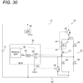
- Fig. 6 is a schematic diagram showing a first embodiment of a circuit configuration of the power supply unit of the aerosol inhaler shown in Fig. 1 .
- the power supply unit 10 includes, as main circuit configurations, the power supply 12, the discharge terminal 41 where the first cartridge 20 including the load 21 is detachably attached, the MCU 50, a low drop out (LDO) regulator 60, a switch 62, a first element 63 having a first electric resistance value R 1 , a second element 64 having a second electric resistance value R 2 and a third element 65 having a third electric resistance value R 3 .
- LDO low drop out
- Each of the first element 63, the second element 64, and the third element 65 is an element having an electric resistance value, for example, a resistor, a diode, or a transistor.
- the first element 63, the second element 64, and the third element 65 are resistors.
- the switch 62 is a switching element such as a transistor that switches between blocking and conduction of a wiring path.
- the switch 62 is a normally-off type insulated gate bipolar transistor (IGBT) that is turned on (conducted) upon receiving a high-level turn-on command signal supplied from the MCU 50 and is turned off (blocked) upon receiving a low-level turn-off command signal supplied from the MCU 50.
- the switch 61 is a normally-off type IGBT, like the switch 62.
- a field effect transistor (FET) may also be used as the switch 61 or the switch 62 instead of the IGBT.
- the LDO regulator 60 and the MCU 50 are connected in series to the power supply 12.
- the LDO regulator 60 steps down and outputs a voltage from the power supply 12.
- An output voltage of the LDO regulator 60 (hereinafter, referred to as a reference voltage V REF ) is supplied to the MCU 50 as an operation voltage of the MCU 50.
- the main positive bus LU is a line on a high potential side
- the main negative bus line LD is a line on a low potential side.
- the main positive bus LU is a line having a highest potential in the electric circuit of the power supply unit 10.
- the main negative bus LD is a line having a lower potential than the main positive bus LU.
- the main negative bus LD is a line having a lowest potential (specifically, 0 V) in the electric circuit of the power supply unit 10.
- the first element 63 and the load 21 are connected in series to form the first series circuit C1.
- the second element 64 and the third element 65 are connected in series to form the second series circuit C2.
- the first series circuit C1 and the second series circuit C2 are connected in parallel between the main positive bus LU and the main negative bus LD. Specifically, a collector of the switch 62 is connected to the main positive bus LU, and the first element 63 and the second element 64 are connected in parallel to an emitter of the switch 62. The load 21 and the third element 65 are connected in parallel to the main negative bus LD. The load 21 is connected to the first element 63, and the third element 65 is connected to the second element 64.
- the first series circuit C1 is connected to the MCU 50. Specifically, in the first series circuit C1, a first connection node between the first element 63 and the load 21 is connected to the MCU 50. An emitter of the switch 61 is connected between the first connection node and the load 21 in the first series circuit C1. A collector of the switch 61 is connected to the main positive bus LU.
- the second series circuit C2 is connected to the MCU 50. Specifically, in the second series circuit C2, a second connection node between the second element 64 and the third element 65 is connected to the MCU 50.
- the MCU 50 includes the first operational amplifier 56, the analog-to-digital converter (ADC) 57, the processor 55, and a second operational amplifier 58 whose amplification factor is 1. In all embodiments, at least one of the first operational amplifier 56, the ADC 57, and the second operational amplifier 58 may be provided outside the MCU 50.
- ADC analog-to-digital converter
- the first operational amplifier 56 includes a non-inversion input terminal (+) and an inversion input terminal (-), amplifies a differential input value obtained by subtracting a potential V- input to the inversion input terminal from a potential V+ input to the non-inversion input terminal by a predetermined amplification factor A and outputs the amplified differential input value.
- the differential input value changes when the electric resistance value of the load 21 changes in accordance with the temperature thereof.
- an output signal of the first operational amplifier 56 changes when the electric resistance value of the load 21 changes in accordance with the temperature thereof.
- the first operational amplifier 56 is treated as an input-output rail-to-rail type operational amplifier.
- the first operational amplifier 56 includes a pair of power supply terminals.
- the reference voltage V REF is supplied from the LDO regulator 60 to the power supply terminal on the high potential side (hereinafter, referred to as a positive power supply terminal).
- the power supply terminal on the low potential side (hereinafter, referred to as a negative power supply terminal) is connected to the main negative bus LD.
- an upper limit value of a range of the differential input value that can be amplified by the first operational amplifier 56 (hereinafter referred to as an amplification range) is a potential of the positive power supply terminal (reference voltage V REF as an example), and a lower limit value of the amplification range is a potential of the negative power supply terminal (0V). Accordingly, when the differential input value is below 0 V, the differential input value is clipped to 0 V (such a phenomenon is referred to as a lower limit clip). Similarly, when the differential input value is above the reference voltage V REF , the differential input value is clipped to the reference voltage V REF (such a phenomenon is referred to as an upper limit clip).
- the first series circuit C1 is connected to the non-inversion input terminal of the first operational amplifier 56. Specifically, the non-inversion input terminal of the first operational amplifier 56 is connected to the first connection node between the first element 63 and the load 21 in the first series circuit C1.
- the second series circuit C2 is connected indirectly to the inversion input terminal of the first operational amplifier 56. Specifically, the inversion input terminal of the first operational amplifier 56 is connected, via the second operational amplifier 58, to the second connection node between the second element 64 and the third element 65 in the second series circuit C2.
- the second operational amplifier 58 functions to lower the lower limit value of the amplification range of the first operational amplifier 56 (that is, the potential of the negative power supply terminal of the first operational amplifier 56) in a pseudo manner. Due to presence of the second operational amplifier 58, the differential input value of the first operational amplifier 56 is raised by the predetermined potential V PSEUDO . As a result, even when a potential of the first connection node between the first element 63 and the load 21 is less than a potential of the second connection node between the second element 64 and the third element 65, it is possible to prevent the occurrence of the lower limit clip, and it is possible to detect the temperature of the load 21 with high accuracy.
- Fig. 7 shows an example of a supply circuit of the predetermined potential V PSEUDO of the power supply unit of a first embodiment shown in Fig. 6 .
- This circuit includes a fourth element 71 which has a fourth electric resistance value R 4 , a fifth element 72 which has a fifth electric resistance value R 5 , and an operational amplifier 73.
- Each of the fourth element 71 and the fifth element 72 is an element having an electric resistance value, for example, a resistor, a diode, or a transistor.
- the fourth element 71 and the fifth element 72 are resistors.
- the fourth element 71 and the fifth element 72 are connected in series.
- a circuit that supplies the reference voltage V REF (for example, the LDO regulator 60) is connected to a terminal, which is located on a side opposite to the side of the fifth element 72, of the fourth element 71.
- the main negative bus LD is connected to a terminal, which is located on a side opposite to the side of the fourth element 71, of the fifth element 72.
- the predetermined potential V PSEUDO can be generated by dividing the reference voltage V REF which serves as an input voltage. According to such a generation circuit, it is easy to set the predetermined potential V PSEUDO to a desired value by adjusting the fourth electric resistance value R 4 and the fifth electric resistance value R 5 . In order to simplify the circuit, it is also possible to directly use the reference voltage V REF as the predetermined potential V PSEUDO .
- the supply circuit of the predetermined potential V PSEUDO is not limited to Fig. 7 , and may also be an LDO regulator or a DC/DC converter that is separate from the LDO regulator 60. That is, the predetermined potential V PSEUDO may also be generated by stepping down the reference voltage V REF serving as the input voltage.
- the ADC 57 converts the output signal of the first operational amplifier 56 into a digital signal and outputs the digital signal.
- the ADC 57 is operated with the reference voltage V REF .
- the MCU 50 includes, as functional blocks implemented by the processor 55 executing programs stored in the ROM, an aerosol generation request detector 51, a temperature detector 52, a power controller 53, and a notification controller 54.
- the aerosol generation request detector 51 detects an aerosol generation request based on an output result of the intake sensor 15.
- the intake sensor 15 is configured to output a value of a pressure (internal pressure) change in the power supply unit 10 caused by inhale of the user through the inhale port 32.
- the intake sensor 15 is, for example, a pressure sensor that outputs an output value (for example, a voltage value or a current value) corresponding to an internal pressure that changes in accordance with a flow rate of air inhaled from the intake port (not shown) toward the inhale port 32 (that is, the puff operation of the user).
- the intake sensor 15 may be constituted by a condenser microphone or the like.
- the intake sensor 15 may output an analog value, or may output a digital value converted from the analog value.
- the temperature detector 52 detects the temperature of the load 21 based on the output signal of the first operational amplifier 56 shown in Fig. 6 .
- the switch 61 is turned off while the switch 62 is turned on, currents flow in the first series circuit C1 and the second series circuit C2 respectively, and the temperature detector 52 detects the temperature of the load 21 based on the output signal of the first operational amplifier 56 at this time.
- the notification controller 54 determines that the second cartridge 30 has been used up (that is, a remaining amount is zero or empty), and notifies the replacement timing of the second cartridge 30.
- the power controller 53 When the temperature of the load 21 detected by the temperature detector 52 exceeds a predetermined upper limit temperature T MAX , the power controller 53 performs control to stop heating of the load 21 (discharge to the load 21). When a temperature of the power supply 12 detected by a thermistor (not shown) or the like is lower than a predetermined lower limit temperature T MIN , the power controller 53 performs control to disallow the heating of the load 21 (discharge to the load 21). When the temperature of the power supply 12 is near the lower limit temperature T MIN or lower than the lower limit temperature T MIN , the temperature of the power supply 12 and the temperature of the load 21 are substantially equal. That is, in the aerosol inhaler 1, the load 21 operates in an operating temperature range that is equal to or higher than the lower limit temperature T MIN and equal to or lower than the upper limit temperature T MAX
- the processor 55 of the MCU 50 Upon detecting the aerosol generation request, the processor 55 of the MCU 50 sends a turn-on command to the switch 61, and sends a turn-off command to the switch 62. In response to such commands, the switch 61 is turned on, and the switch 62 is turned off.
- R HTR electric resistance value
- the processor 55 After a lapse of a predetermined time from a start of the heating of the load 21, the processor 55 sends the turn-off command to the switch 61, and sends the turn-on command to the switch 62.
- the switch 61 When the switch 61 is turned off while the switch 62 is turned on in response to such commands, currents flow to the first series circuit C1 and the second series circuit C2.
- the differential input value is amplified by the first operational amplifier 56, subjected to digital conversion performed by the ADC 57, and input to the processor 55.
- the processor 55 detects the temperature of the load 21 based on an input signal from the ADC 57.
- the processor 55 After detecting the temperature of the load 21, the processor 55 sends the turn-on command to the switch 61, and sends the turn-off command to the switch 62 to start generation of the aerosol again.
- the temperature of the load 21 is detected at high frequency during the generation of the aerosol in response to the aerosol generation request.
- a value of the predetermined potential V PSEUDO is determined in such a manner that the differential input value of the first operational amplifier 56 is larger than the potential of the negative power supply terminal of the first operational amplifier 56 in a state where a potential of the first connection node between the first element 63 and the load 21 is less than a potential of the second connection node between the second element 64 and the third element 65 while the temperature of the load 21 is within the operating temperature range.
- Fig. 8 is a graph showing an example of the differential input value of the first operational amplifier 56 in the power supply unit 10 of the first embodiment shown in Fig. 6 .
- a vertical axis represents a voltage (potential) while a horizontal axis represents the temperature of the load 21.
- a graph denoted by "V+” represents the potential of the first connection node between the first element 63 and the load 21.
- a graph denoted by “V - "' represents the potential of the second connection node between the second element 64 and the third element 65.
- a graph denoted by "V+ - V-' + V PSEUDO " represents the differential input value of the first operational amplifier 56.
- a configuration in which the second connection node and the inversion input terminal of the first operational amplifier 56 are directly connected without the second operational amplifier 58 is described as a first reference circuit configuration.
- a graph denoted by "V+ - V-'" represents the differential input value of the first operational amplifier 56 in the first reference circuit configuration.
- the potential "V+" of the first connection node is less than the potential "V - "' of the second connection node. Therefore, in the first reference circuit configuration, the lower limit clip occurs in the operating temperature range.
- the value of the predetermined potential V PSEUDO is determined in such a manner that the differential input value of the first operational amplifier 56 is larger than 0 V. Further, in the first embodiment shown in Fig. 6 , the value of the predetermined potential V PSEUDO is determined in such a manner that the differential input value of the first operational amplifier 56 is smaller than the potential of the positive power supply terminal (reference voltage V REF ) at the upper limit temperature T MAX of the operating temperature range.
- a configuration in which the potential "V+" of the first connection node is less than the potential "V - "' of the second connection node in the operating temperature range can be adopted as the bridge circuit. Therefore, restrictions on electric resistance values of each element of the bridge circuit can be relaxed, and a degree of freedom in design can be improved.
- the state where the potential "V+” of the first connection node is less than the potential "V - '" of the second connection node may also be caused by a manufacturing error of the electric resistance value R HTR of the load 21.
- the electric resistance value R HTR of the load 21 can generally have a manufacturing error of about ⁇ 10%. Therefore, for example, even when the bridge circuit can be designed in such a manner that the potential "V+” of the first connection node is equal to or higher than the potential "V - '" of the second connection node in the operating temperature range, the state where the potential "V+” of the first connection node is less than the potential "V - "' of the second connection node may still occur due to the manufacturing error. Therefore, it is desirable that the value of the predetermined potential V PSEUDO is determined in consideration of the manufacturing error of the electric resistance value R HTR of the load 21.
- a graph denoted by "V + '" indicates the potential of the first connection node when there is an error of - 10% in the electric resistance value R HTR of the load 21 as compared with a design value.
- the differential input value of the first operational amplifier 56 in the first reference circuit configuration is as shown in a graph "V + ' - V - '" in Fig. 9 , and the lower limit clip occurs in a temperature range Tr2 in the operating temperature range.
- the value of the predetermined potential V PSEUDO is determined in such a manner that the differential input value of the first operational amplifier 56 is larger than 0 V in the temperature range Tr2 in which the potential of the first connection node is less than the potential of the second connection node in the case where there an error of -10% in the electric resistance value R HTR of the load 21 as compared with the design value.
- the value of the predetermined potential V PSEUDO is determined in such a manner that the differential input value of the first operational amplifier 56 is less than the potential of the positive power supply terminal of the first operational amplifier 56.
- a graph shown by "V + '- V - ' + V PSEUDO " shown in Fig. 9 shows the differential input value of the first operational amplifier 56 when there is an error of -10% in the electric resistance value R HTR of the load 21.
- the differential input value of the first operational amplifier 56 is between the potential of the negative power supply terminal and the potential of the positive power supply terminal in the operating temperature range when there is a manufacturing error in the load 21. Therefore, the occurrence of the lower limit clip and the upper limit clip can be prevented in the first operational amplifier 56, and the detection accuracy of the temperature of the load 21 can be improved.
- Fig. 10 is a schematic view showing a first modification of the circuit configuration of the power supply unit 10 of the first embodiment shown in Fig. 6 .
- the power supply unit 10 shown in Fig. 10 is the same as the circuit configuration of Fig. 6 except that a connection relationship between the first operational amplifier 56, the second operational amplifier 58 and the bridge circuit is changed.
- the non-inversion input terminal of the second operational amplifier 58 is connected to the first connection node between the first element 63 and the load 21.
- the non-inversion input terminal of the first operational amplifier 56 is connected to the second connection node between the second element 64 and the third element 65.
- the value of the predetermined potential V PSEUDO is determined in such a manner that the differential input value of the first operational amplifier 56 is larger than the potential of the negative power supply terminal of the first operational amplifier 56 in a state where the potential of the second connection node is less than the potential of the first connection node while the temperature of the load 21 is within the operating temperature range.
- the potential "V+" of the second connection node is less than the potential "V - '" of the first connection node in a temperature range Tr3 in the operating temperature range. Therefore, in the case of the second reference circuit configuration, the lower limit clip occurs in the temperature range Tr3 in the operating temperature range. When there is an error of +10% in the electric resistance value R HTR of the load 21, the lower limit clip does not occur.
- the value of the predetermined potential V PSEUDO is determined in such a manner that the differential input value of the first operational amplifier 56 is larger than 0 V. Further, in the power supply unit 10 shown in Fig. 10 , the value of the predetermined potential V PSEUDO is determined in such a manner that the differential input value of the first operational amplifier 56 is smaller than the potential of the positive power supply terminal (reference voltage V REF ) in a state where there is an error of +10% in the electric resistance value R HTR of the load 21 while the temperature of the load 21 is equal to the lower limit temperature T MIN . Further, in the power supply unit 10 shown in Fig.
- the differential input value of the first operational amplifier 56 is between the potential of the negative power supply terminal and the potential of the positive power supply terminal in the operating temperature range when there is a manufacturing error in the load 21. Therefore, the occurrence of the lower limit clip and the upper limit clip can be prevented in the first operational amplifier 56, and the detection accuracy of the temperature of the load 21 can be improved.
- Fig. 13 is a graph showing an example of the differential input value of the first operational amplifier 56 in the power supply unit 10 shown in Fig. 12 .
- a graph denoted by "V+” represents the potential of the first connection node between the first element 63 and the load 21.
- a graph denoted by “V - "' represents the potential of the second connection node between the second element 64 and the third element 65.
- a graph denoted by "V+ - V-' + V PSEUDO " represents the differential input value of the first operational amplifier 56.
- a configuration in which the second connection node and the inversion input terminal of the first operational amplifier 56 are directly connected without the second operational amplifier 58 is described as a third reference circuit configuration.
- a graph denoted by "V+ - V - '" represents the differential input value of the first operational amplifier 56 in the third reference circuit configuration.
- the electric resistance value R HTR of the load 21 is designed in such a manner that the potential "V+" of the first connection node and the potential "V - "' of the second connection node are equal in a state where the temperature of the load 21 is equal to the upper limit temperature T MAX .
- Fig. 13 shows an example in which there is an error of -10% in the electric resistance value R HTR of the load 21.
- the potential "V+" of the first connection node is less than the potential "V - '" of the second connection node in a temperature range Tr4 in the operating temperature range. Therefore, in the case of the third reference circuit configuration, the lower limit clip occurs in the temperature range Tr4 in the operating temperature range. When there is an error of +10% in the electric resistance value R HTR of the load 21, the lower limit clip does not occur.
- Fig. 14 is a schematic view showing a third modification of the circuit configuration of the power supply unit of the first embodiment shown in Fig. 6 .
- the power supply unit 10 shown in Fig. 14 is the same as the circuit configuration of Fig. 12 except that the connection relationship between the first operational amplifier 56, the second operational amplifier 58 and the bridge circuit is changed.
- the non-inversion input terminal of the second operational amplifier 58 is connected to the first connection node between the first element 63 and the load 21.
- the non-inversion input terminal of the first operational amplifier 56 is connected to the second connection node between the second element 64 and the third element 65.
- Fig. 15 is a graph showing an example of the differential input value of the first operational amplifier 56 in the power supply unit 10 shown in Fig. 14 .
- a graph denoted by "V+” represents the potential of the second connection node between the second element 64 and the third element 65.
- a graph denoted by “V - "' represents the potential of the first connection node between the first element 63 and the load 21.
- a graph denoted by "V+ - V-' + V PSEUDO " represents the differential input value of the first operational amplifier 56.
- a graph denoted by "V+ - V - '" represents the differential input value of the first operational amplifier 56 in the fourth reference circuit configuration.
- the electric resistance value R HTR of the load 21 is designed in such a manner that the potential "V+" of the second connection node and the potential "V - "' of the first connection node are equal in a state where the temperature of the load 21 is equal to the lower limit temperature T MIN .
- Fig. 15 shows an example in which there is an error of +10% in the electric resistance value R HTR of the load 21.
- the potential "V+" of the second connection node is less than the potential "V - '" of the first connection node in a temperature range Tr5 in the operating temperature range. Therefore, in the case of the fourth reference circuit configuration, the lower limit clip occurs in the temperature range Tr5 in the operating temperature range. When there is an error of -10% in the electric resistance value R HTR of the load 21, the lower limit clip does not occur.
- the value of the predetermined potential V PSEUDO is determined in such a manner that the differential input value of the first operational amplifier 56 is smaller than the potential of the positive power supply terminal (reference voltage V REF ) in a state where there is an error of -10% in the electric resistance value R HTR of the load 21 while the temperature of the load 21 is equal to the upper limit temperature T MAX
- the differential input value of the first operational amplifier 56 is between the potential of the negative power supply terminal and the potential of the positive power supply terminal in the operating temperature range when there is a manufacturing error in the load 21. Therefore, the occurrence of the lower limit clip and the upper limit clip can be prevented in the first operational amplifier 56, and the detection accuracy of the temperature of the load 21 can be improved.
- the value of the predetermined potential V PSEUDO may also be a value equal to the potential of the negative power supply terminal of the first operational amplifier 56 in a state where: 1. there is a manufacturing error in the electric resistance value R HTR of the load 21, 2. the temperature of the load 21 is outside the operating temperature range, and 3. a potential of a connection node of a series circuit on a side, which is connected to the non-inversion input terminal of the first operational amplifier 56, of the bridge circuit is less than a potential of a connection node of a series circuit on a side which is connected to the inversion input terminal of the first operational amplifier 56. That is, the occurrence of the lower limit clip in the first operational amplifier 56 may be allowed outside the operating temperature range. In this way, an increase in the value of the predetermined potential V PSEUDO can be prevented, and a size of the circuit can be reduced.
- the rail splitter circuit 59 generates, from the reference voltage V REF (input voltage) generated by the LDO regulator 60, two potentials having the same absolute value and different positive and negative values (a positive potential of (V REF /2) and a negative potential of (-V REF /2)).
- the positive potential (V REF /2) generated by the rail splitter circuit 59 is input to the positive power supply terminal of the first operational amplifier 56
- the negative potential (-V REF /2) generated by the rail splitter circuit 59 is input to the negative power supply terminal of the first operational amplifier 56.
- the absolute value of the generated potential can be adjusted by adjusting at least one of electric resistance values of the resistors 591, 592 and the input voltage.
- the occurrence of the upper limit clip in the first operational amplifier 56 can be prevented in the operating temperature range by determining at least one of the electric resistance values of the resistors 591, 592 and the input voltage in such a manner that the differential input value of the first operational amplifier 56 is smaller than the positive potential generated by the rail splitter circuit 59.
- the potential "V+" of the first connection node is less than the potential "V - "' of the second connection node.
- the value (absolute value) of the negative potential generated by the rail splitter circuit 59 may be determined in such a manner that the differential input value of the first operational amplifier 56 is larger than the potential of the negative power supply terminal (the minimum value that can be acquired by the first operational amplifier 56 in the state where the operational amplifier 56 is not the input-output rail-to-rail type operational amplifier).
- the value (absolute value) of the positive potential generated by the rail splitter circuit 59 may be determined in such a manner that the differential input value of the first operational amplifier 56 is smaller than the potential of the positive power supply terminal (the maximum value that can be acquired by the first operational amplifier 56 in the state where the operational amplifier 56 is not the input-output rail-to-rail type operational amplifier).
- a configuration in which the potential "V+" of the first connection node is less than the potential "V-" of the second connection node in the operating temperature range can be adopted as the bridge circuit. Therefore, the restrictions on the electric resistance values of each element of the bridge circuit can be relaxed, and the degree of freedom in design can be improved.
- the state where the potential "V+" of the first connection node is less than the potential "V-" of the second connection node may be caused by the manufacturing error of the electric resistance value R HTR of the load 21. Therefore, the values of the potentials generated by the rail splitter circuit 59 are desirably designed in consideration of the manufacturing error of the electric resistance value R HTR of the load 21.
- Fig. 18 is a graph showing another example of the differential input value of the first operational amplifier 56 in the power supply unit 10 of the second embodiment shown in Fig. 16 .
- the electric resistance value R HTR of the load 21 is designed in such a manner that the potential "V+" of the first connection node and the potential "V-" of the second connection node are equal in a state where the temperature of the load 21 is equal to the lower limit temperature T MIN .
- a graph denoted by "V+ - V-" represents the differential input value of the first operational amplifier 56 when there is no error in the electric resistance value R HTR of the load 21.
- a graph denoted by "V + "' indicates the potential of the first connection node when there is an error of - 10% in the electric resistance value R HTR of the load 21 as compared with the design value.
- the differential input value of the first operational amplifier 56 is as shown in a graph "V+' - V-" in Fig. 18 .
- the value (absolute value) of the negative potential generated by the rail splitter circuit 59 may be determined in such a manner that the differential input value of the first operational amplifier 56 is larger than the potential of the negative power supply terminal (the minimum value that can be acquired by the first operational amplifier 56 in the state where the operational amplifier 56 is not the input-output rail-to-rail type operational amplifier).
- the value (absolute value) of the positive potential generated by the rail splitter circuit 59 may be determined in such a manner that the differential input value of the first operational amplifier 56 is smaller than the potential of the positive power supply terminal (the maximum value that can be acquired by the first operational amplifier 56 in the state where the operational amplifier 56 is not the input-output rail-to-rail type operational amplifier).
- the potential "V + "' of the first connection node is not less than the potential "V-" of the second connection node in the operating temperature range.
- the values (absolute value) of the potentials generated by the rail splitter circuit 59 may be determined in such a manner that the differential input value of the first operational amplifier 56 is smaller than the potential of the positive power supply terminal (the maximum value that can be acquired by the first operational amplifier 56 in the state where the operational amplifier 56 is not the input-output rail-to-rail type operational amplifier).
- the value of the negative potential generated by the rail splitter circuit 59 is determined in such a manner that the differential input value of the first operational amplifier 56 is larger than the potential of the negative power supply terminal (the minimum value that can be acquired by the first operational amplifier 56 in the state where the operational amplifier 56 is not the input-output rail-to-rail type operational amplifier) in a state where: 1. there is an error of -10% in the electric resistance value R HTR of the load 21, 2. the temperature of the load 21 is within the operating temperature range, and 3. the potential "V+" of the first connection node is less than the potential "V-" of the second connection node.
- the value of the negative potential generated by the rail splitter circuit 59 is determined in such a manner that the differential input value of the first operational amplifier 56 is smaller than the potential of the positive power supply terminal (the maximum value that can be acquired by the first operational amplifier 56 in the state where the operational amplifier 56 is not the input-output rail-to-rail type operational amplifier) in a state where: 1. there is an error of -10% in the electric resistance value R HTR of the load 21, 2. the temperature of the load 21 is within the operating temperature range, and 3. the potential "V+" of the first connection node is equal to or higher than the potential "V-" of the second connection node or a state where: 1.
- the differential input value of the first operational amplifier 56 is between the potential of the negative power supply terminal (or the minimum value) and the potential of the positive power supply terminal (or the maximum value) in the operating temperature range when there is a manufacturing error in the load 21. Therefore, the occurrence of the lower limit clip and the upper limit clip can be prevented in the first operational amplifier 56, and the detection accuracy of the temperature of the load 21 can be improved.
- Fig. 19 is a schematic view showing a first modification of the circuit configuration of the power supply unit 10 of the second embodiment shown in Fig. 16 .
- the power supply unit 10 shown in Fig. 19 is the same as the circuit configuration of Fig. 16 except that a connection relationship between the first operational amplifier 56 and the bridge circuit is changed.
- the inversion input terminal of the first operational amplifier 56 is connected to the first connection node between the first element 63 and the load 21.
- the non-inversion input terminal of the first operational amplifier 56 is connected to the second connection node between the second element 64 and the third element 65.
- Fig. 20 is a graph showing an example of the differential input value of the first operational amplifier 56 in the power supply unit 10 shown in Fig. 19 .
- a graph denoted by "V+” represents the potential of the second connection node between the second element 64 and the third element 65.
- a graph denoted by "V-” represents the potential of the first connection node between the first element 63 and the load 21.
- a graph denoted by "V+ - V-" represents the differential input value of the first operational amplifier 56.
- the electric resistance value R HTR of the load 21 is designed in such a manner that the potential "V+" of the second connection node and the potential "V-" of the first connection node are equal in the state where the temperature of the load 21 is equal to the upper limit temperature T MAX Fig. 20 shows an example in which there is an error of +10% in the electric resistance value R HTR of the load 21.
- the potential "V+" of the first connection node is less than the potential "V-" of the second connection node in a temperature range Tr13 in the operating temperature range.
- the value (absolute value) of the negative potential generated by the rail splitter circuit 59 may be determined in such a manner that the differential input value of the first operational amplifier 56 is larger than the potential of the negative power supply terminal (the minimum value that can be acquired by the first operational amplifier 56 in the state where the operational amplifier 56 is not the input-output rail-to-rail type operational amplifier).
- the value (absolute value) of the positive potential generated by the rail splitter circuit 59 may be determined in such a manner that the differential input value of the first operational amplifier 56 is smaller than the potential of the positive power supply terminal (the maximum value that can be acquired by the first operational amplifier 56 in the state where the operational amplifier 56 is not the input-output rail-to-rail type operational amplifier).
- the values (absolute value) of the potentials generated by the rail splitter circuit 59 may be determined in such a manner that the differential input value of the first operational amplifier 56 is smaller than the potential of the positive power supply terminal (the maximum value that can be acquired by the first operational amplifier 56 in the state where the operational amplifier 56 is not the input-output rail-to-rail type operational amplifier).
- the value of the negative potential generated by the rail splitter circuit 59 is determined in such a manner that the differential input value of the first operational amplifier 56 is larger than the potential of the negative power supply terminal (the minimum value that can be acquired by the first operational amplifier 56 in the state where the operational amplifier 56 is not the input-output rail-to-rail type operational amplifier) in a state where: 1. there is an error of +10% in the electric resistance value R HTR of the load 21, 2. the temperature of the load 21 is within the operating temperature range, and 3. the potential "V+" of the second connection node is less than the potential "V-" of the first connection node.
- the value of the negative potential generated by the rail splitter circuit 59 is determined in such a manner that the differential input value of the first operational amplifier 56 is smaller than the potential of the positive power supply terminal (the maximum value that can be acquired by the first operational amplifier 56 in the state where the operational amplifier 56 is not the input-output rail-to-rail type operational amplifier) in a state where: 1. there is an error of +10% in the electric resistance value R HTR of the load 21, 2. the temperature of the load 21 is within the operating temperature range, and 3. the potential "V+" of the second connection node is equal to or higher than the potential "V-" of the first connection node or a state where: 1.
- the differential input value of the first operational amplifier 56 is between the potential of the negative power supply terminal (or the minimum value) and the potential of the positive power supply terminal (or the maximum value) in the operating temperature range when there is a manufacturing error in the load 21. Therefore, the occurrence of the lower limit clip and the upper limit clip can be prevented in the first operational amplifier 56, and the detection accuracy of the temperature of the load 21 can be improved.
- Fig. 21 is a schematic view showing a second modification of the circuit configuration of the power supply unit 10 of the second embodiment shown in Fig. 16 .
- the power supply unit 10 shown in Fig. 21 is the same as the circuit configuration of Fig. 16 except that the positions of the first element 63 and the load 21 are reversed in the first series circuit C1 while the position of the switch 61 is changed.
- the switch 61 is connected between the first connection node and the main negative bus LD.
- the load 21 is heated when the switch 61 and the switch 62 are both turned on.
- the temperature of the load 21 is detected when the switch 61 is turned off while the switch 62 is turned on.
- Fig. 22 is a graph showing an example of the differential input value of the first operational amplifier 56 in the power supply unit 10 shown in Fig. 21 .
- a graph denoted by "V+” represents the potential of the first connection node between the first element 63 and the load 21.
- a graph denoted by "V-” represents the potential of the second connection node between the second element 64 and the third element 65.
- a graph denoted by "V+ - V-" represents the differential input value of the first operational amplifier 56.
- the electric resistance value R HTR of the load 21 is designed in such a manner that the potential "V+" of the first connection node and the potential "V-" of the second connection node are equal in a state where the temperature of the load 21 is equal to the upper limit temperature T MAX .
- Fig. 22 shows an example in which there is an error of -10% in the electric resistance value R HTR of the load 21.
- the potential "V+" of the first connection node is less than the potential "V-" of the second connection node in a temperature range Tr14 in the operating temperature range.
- the value (absolute value) of the negative potential generated by the rail splitter circuit 59 may be determined in such a manner that the differential input value of the first operational amplifier 56 is larger than the potential of the negative power supply terminal (the minimum value that can be acquired by the first operational amplifier 56 in the state where the operational amplifier 56 is not the input-output rail-to-rail type operational amplifier).
- the value (absolute value) of the positive potential generated by the rail splitter circuit 59 may be determined in such a manner that the differential input value of the first operational amplifier 56 is smaller than the potential of the positive power supply terminal (the maximum value that can be acquired by the first operational amplifier 56 in the state where the operational amplifier 56 is not the input-output rail-to-rail type operational amplifier).
- the values (absolute value) of the potentials generated by the rail splitter circuit 59 may be determined in such a manner that the differential input value of the first operational amplifier 56 is smaller than the potential of the positive power supply terminal (the maximum value that can be acquired by the first operational amplifier 56 in the state where the operational amplifier 56 is not the input-output rail-to-rail type operational amplifier).
- the value of the negative potential generated by the rail splitter circuit 59 is determined in such a manner that the differential input value of the first operational amplifier 56 is larger than the potential of the negative power supply terminal (the minimum value that can be acquired by the first operational amplifier 56 in the state where the operational amplifier 56 is not the input-output rail-to-rail type operational amplifier) in the state where: 1. there is an error of -10% in the electric resistance value R HTR of the load 21, 2. the temperature of the load 21 is within the operating temperature range, and 3. the potential "V+" of the first connection node is less than the potential "V-" of the second connection node.
- the value of the negative potential generated by the rail splitter circuit 59 is determined in such a manner that the differential input value of the first operational amplifier 56 is smaller than the potential of the positive power supply terminal (the maximum value that can be acquired by the first operational amplifier 56 in the state where the operational amplifier 56 is not the input-output rail-to-rail type operational amplifier) in the state where: 1. there is an error of -10% in the electric resistance value R HTR of the load 21, 2. the temperature of the load 21 is within the operating temperature range, and 3. the potential "V+" of the first connection node is equal to or higher than the potential "V-" of the second connection node or the state where: 1.
- the differential input value of the first operational amplifier 56 is between the potential of the negative power supply terminal (or the minimum value) and the potential of the positive power supply terminal (or the maximum value) in the operating temperature range when there is a manufacturing error in the load 21. Therefore, the occurrence of the lower limit clip and the upper limit clip can be prevented in the first operational amplifier 56, and the detection accuracy of the temperature of the load 21 can be improved.
- Fig. 23 is a schematic view showing a third modification of the circuit configuration of the power supply unit of the second embodiment shown in Fig. 16 .
- the power supply unit 10 shown in Fig. 23 is the same as the circuit configuration of Fig. 21 except that the connection relationship between the first operational amplifier 56 and the bridge circuit is changed.
- the inversion input terminal of the first operational amplifier 56 is connected to the first connection node between the first element 63 and the load 21.
- the non-inversion input terminal of the first operational amplifier 56 is connected to the second connection node between the second element 64 and the third element 65.
- Fig. 24 is a graph showing an example of the differential input value of the first operational amplifier 56 in the power supply unit 10 shown in Fig. 23 .
- a graph denoted by "V+” represents the potential of the second connection node between the second element 64 and the third element 65.
- a graph denoted by "V-” represents the potential of the first connection node between the first element 63 and the load 21.
- a graph denoted by "V+ - V-" represents the differential input value of the first operational amplifier 56.
- the electric resistance value R HTR of the load 21 is designed in such a manner that the potential "V+" of the second connection node and the potential "V-" of the first connection node are equal in the state where the temperature of the load 21 is equal to the lower limit temperature T MIN .
- Fig. 24 shows an example in which there is an error of +10% in the electric resistance value R HTR of the load 21.
- the potential "V+" of the second connection node is less than the potential "V-" of the first connection node in a temperature range Tr15 in the operating temperature range.
- the value (absolute value) of the negative potential generated by the rail splitter circuit 59 may be determined in such a manner that the differential input value of the first operational amplifier 56 is larger than the potential of the negative power supply terminal (the minimum value that can be acquired by the first operational amplifier 56 in the state where the operational amplifier 56 is not the input-output rail-to-rail type operational amplifier).
- the value (absolute value) of the positive potential generated by the rail splitter circuit 59 may be determined in such a manner that the differential input value of the first operational amplifier 56 is smaller than the potential of the positive power supply terminal (the maximum value that can be acquired by the first operational amplifier 56 in the state where the operational amplifier 56 is not the input-output rail-to-rail type operational amplifier).
- the values (absolute value) of the potentials generated by the rail splitter circuit 59 may be determined in such a manner that the differential input value of the first operational amplifier 56 is smaller than the potential of the positive power supply terminal (the maximum value that can be acquired by the first operational amplifier 56 in the state where the operational amplifier 56 is not the input-output rail-to-rail type operational amplifier).
- the value of the negative potential generated by the rail splitter circuit 59 is determined in such a manner that the differential input value of the first operational amplifier 56 is larger than the potential of the negative power supply terminal (the minimum value that can be acquired by the first operational amplifier 56 in the state where the operational amplifier 56 is not the input-output rail-to-rail type operational amplifier) in the state where: 1. there is an error of +10% in the electric resistance value R HTR of the load 21, 2. the temperature of the load 21 is within the operating temperature range, and 3. the potential "V+" of the second connection node is less than the potential "V-" of the first connection node.
- the value of the negative potential generated by the rail splitter circuit 59 is determined in such a manner that the differential input value of the first operational amplifier 56 is smaller than the potential of the positive power supply terminal (the maximum value that can be acquired by the first operational amplifier 56 in the state where the operational amplifier 56 is not the input-output rail-to-rail type operational amplifier) in the state where: 1. there is an error of +10% in the electric resistance value R HTR of the load 21, 2. the temperature of the load 21 is within the operating temperature range, and 3. the potential "V+" of the second connection node is equal to or higher than the potential "V-" of the first connection node or the state where: 1.
- the differential input value of the first operational amplifier 56 is between the potential of the negative power supply terminal (or the minimum value) and the potential of the positive power supply terminal (or the maximum value) in the operating temperature range when there is a manufacturing error in the load 21. Therefore, the occurrence of the lower limit clip and the upper limit clip can be prevented in the first operational amplifier 56, and the detection accuracy of the temperature of the load 21 can be improved.
- the values (absolute value) of the potentials generated by the rail splitter circuit 59 may be determined in such a manner that the differential input value is between the maximum value and the minimum value that can be acquired by the first operational amplifier 56.
- Fig. 25 is a schematic diagram showing a third embodiment of the circuit configuration of the power supply unit of the aerosol inhaler shown in Fig. 1 .
- the power supply unit 10 shown in Fig. 25 has the same configuration as that of Fig. 6 except that the inversion input terminal of the first operational amplifier 56 is directly connected to the second connection node between the second element 64 and the third element 65 while a negative power supply 12A that supplies a negative potential ("-V REF2 " whose absolute value is smaller than the reference voltage in the example of Fig. 25 ) is connected to the negative power supply terminal of the first operational amplifier 56.
- the lower limit value of the amplification range of the first operational amplifier 56 can be extended in the negative direction by the negative power supply 12A. Therefore, in a state where the temperature of the load 21 is within the operating temperature range while the potential of the first connection node is less than the potential of the second connection node, the occurrence of the lower limit clip in the first operational amplifier 56 can be prevented in the operating temperature range by determining the potential supplied from the negative power supply 12A in such a manner that the differential input value of the first operational amplifier 56 is larger than the potential of the negative power supply terminal (the minimum value that can be acquired by the first operational amplifier 56 in the state where the operational amplifier 56 is not the input-output rail-to-rail type operational amplifier).
- Fig. 26 is a graph showing an example of the differential input value of the first operational amplifier 56 in the power supply unit 10 of the third embodiment shown in Fig. 25 .
- the vertical axis represents the voltage (potential) while the horizontal axis represents the temperature of the load 21.
- a graph denoted by "V+” represents the potential of the first connection node between the first element 63 and the load 21.
- a graph denoted by “V-” represents the potential of the second connection node between the second element 64 and the third element 65.
- a graph denoted by "V+ - V-" represents the differential input value of the first operational amplifier 56.
- the potential "V+" of the first connection node is less than the potential "V-" of the second connection node.
- the potential of the negative power supply 12A may be determined in such a manner that the differential input value of the first operational amplifier 56 is larger than the potential of the negative power supply terminal (the minimum value that can be acquired by the first operational amplifier 56 in the state where the operational amplifier 56 is not the input-output rail-to-rail type operational amplifier).
- the potential of the positive power supply terminal may be determined in such a manner that the differential input value of the first operational amplifier 56 is smaller than the potential of the positive power supply terminal (the maximum value that can be acquired by the first operational amplifier 56 in the state where the operational amplifier 56 is not the input-output rail-to-rail type operational amplifier).
- the configuration in which the potential "V+" of the first connection node is less than the potential "V-" of the second connection node in the operating temperature range can be adopted as the bridge circuit. Therefore, the restrictions on the electric resistance values of each element of the bridge circuit can be relaxed, and the degree of freedom in design can be improved. A degree of freedom in setting the potential of the positive power supply terminal of the first operational amplifier 56 can also be improved.
- the state where the potential "V+" of the first connection node is less than the potential "V-" of the second connection node may be caused by the manufacturing error of the electric resistance value R HTR of the load 21. Therefore, the value of the potential of the negative power supply 12A is desirably designed in consideration of the manufacturing error of the electric resistance value R HTR of the load 21.
- Fig. 27 is a graph showing another example of the differential input value of the first operational amplifier 56 in the power supply unit 10 of the third embodiment shown in Fig. 25 .
- the electric resistance value R HTR of the load 21 is designed in such a manner that the potential "V+" of the first connection node and the potential "V-" of the second connection node are equal in the state where the temperature of the load 21 is equal to the lower limit temperature T MIN .
- a graph denoted by "V+ - V-" represents the differential input value of the first operational amplifier 56 when there is no error in the electric resistance value R HTR of the load 21.
- a graph denoted by "V + '" indicates the potential of the first connection node when there is an error of - 10% in the electric resistance value R HTR of the load 21 as compared with the design value.
- the differential input value of the first operational amplifier 56 is as shown in a graph "V+' - V-" in Fig. 27 .
- the potential of the negative power supply 12A may be determined in such a manner that the differential input value of the first operational amplifier 56 is larger than the potential of the negative power supply terminal (the minimum value that can be acquired by the first operational amplifier 56 in the state where the operational amplifier 56 is not the input-output rail-to-rail type operational amplifier).
- the differential input value of the first operational amplifier 56 is larger than the potential of the negative power supply terminal (the minimum value that can be acquired by the first operational amplifier 56 in the state where the operational amplifier 56 is not the input-output rail-to-rail type operational amplifier).
- the potential of the positive power supply terminal may be determined in such a manner that the differential input value of the first operational amplifier 56 is smaller than the potential of the positive power supply terminal (the maximum value that can be acquired by the first operational amplifier 56 in the state where the operational amplifier 56 is not the input-output rail-to-rail type operational amplifier).
- the potential of the positive power supply terminal may be determined in such a manner that the differential input value of the first operational amplifier 56 is smaller than the potential of the positive power supply terminal (the maximum value that can be acquired by the first operational amplifier 56 in the state where the operational amplifier 56 is not the input-output rail-to-rail type operational amplifier).
- the value of the potential of the negative power supply 12A is determined in such a manner that the differential input value of the first operational amplifier 56 is larger than the potential of the negative power supply terminal (the minimum value that can be acquired by the first operational amplifier 56 in the state where the operational amplifier 56 is not the input-output rail-to-rail type operational amplifier) in a state where: 1. there is an error of -10% in the electric resistance value R HTR of the load 21, 2. the temperature of the load 21 is within the operating temperature range, and 3. the potential "V+" of the first connection node is less than the potential "V-" of the second connection node.
- the potential of the positive power supply terminal of the first operational amplifier 56 is determined in such a manner that the differential input value of the first operational amplifier 56 is smaller than the potential of the positive power supply terminal (the maximum value that can be acquired by the first operational amplifier 56 in the state where the operational amplifier 56 is not the input-output rail-to-rail type operational amplifier) in the state where: 1. there is an error of -10% in the electric resistance value R HTR of the load 21, 2. the temperature of the load 21 is within the operating temperature range, and 3. the potential "V+" of the first connection node is equal to or higher than the potential "V-" of the second connection node or the state where: 1. there is an error of +10% in the electric resistance value R HTR of the load 21, 2. the temperature of the load 21 is within the operating temperature range, and 3. the potential "V+" of the first connection node is equal to or higher than the potential "V-" of the second connection node.
- the differential input value of the first operational amplifier 56 is between the potential of the negative power supply terminal and the potential of the positive power supply terminal in the operating temperature range when there is a manufacturing error in the load 21. Therefore, the occurrence of the lower limit clip and the upper limit clip can be prevented in the first operational amplifier 56, and the detection accuracy of the temperature of the load 21 can be improved.
- Fig. 28 is a schematic view showing a first modification of the circuit configuration of the power supply unit 10 of the third embodiment shown in Fig. 25 .
- the power supply unit 10 shown in Fig. 28 is the same as the circuit configuration of Fig. 25 except that the connection relationship between the first operational amplifier 56 and the bridge circuit is changed.
- the inversion input terminal of the first operational amplifier 56 is connected to the first connection node between the first element 63 and the load 21.
- the non-inversion input terminal of the first operational amplifier 56 is connected to the second connection node between the second element 64 and the third element 65.
- Fig. 29 is a graph showing an example of the differential input value of the first operational amplifier 56 in the power supply unit 10 shown in Fig. 28 .
- a graph denoted by "V+” represents the potential of the second connection node between the second element 64 and the third element 65.
- a graph denoted by "V-” represents the potential of the first connection node between the first element 63 and the load 21.
- a graph denoted by "V+ - V-" represents the differential input value of the first operational amplifier 56.
- the electric resistance value R HTR of the load 21 is designed in such a manner that the potential "V+" of the second connection node and the potential "V-" of the first connection node are equal in the state where the temperature of the load 21 is equal to the upper limit temperature T MAX Fig. 29 shows an example in which there is an error of +10% in the electric resistance value R HTR of the load 21.
- the potential "V+" of the first connection node is less than the potential "V-" of the second connection node in a temperature range Tr23 in the operating temperature range.
- the potential of the negative power supply 12A may be determined in such a manner that the differential input value of the first operational amplifier 56 is larger than the potential of the negative power supply terminal (the minimum value that can be acquired by the first operational amplifier 56 in the state where the operational amplifier 56 is not the input-output rail-to-rail type operational amplifier).
- the potential of the positive power supply terminal of the first operational amplifier 56 may be determined in such a manner that the differential input value of the first operational amplifier 56 is smaller than the potential of the positive power supply terminal (the maximum value that can be acquired by the first operational amplifier 56 in the state where the operational amplifier 56 is not the input-output rail-to-rail type operational amplifier).
- the potential of the positive power supply terminal of the first operational amplifier 56 may be determined in such a manner that the differential input value of the first operational amplifier 56 is smaller than the potential of the positive power supply terminal (the maximum value that can be acquired by the first operational amplifier 56 in the state where the operational amplifier 56 is not the input-output rail-to-rail type operational amplifier).
- the value of the potential of the negative power supply 12A is determined in such a manner that the differential input value of the first operational amplifier 56 is larger than the potential of the negative power supply terminal (the minimum value that can be acquired by the first operational amplifier 56 in the state where the operational amplifier 56 is not the input-output rail-to-rail type operational amplifier) in the state where: 1. there is an error of +10% in the electric resistance value R HTR of the load 21, 2. the temperature of the load 21 is within the operating temperature range, and 3. the potential "V+" of the second connection node is less than the potential "V-" of the first connection node.
- the value of the potential of the positive power supply terminal of the first operational amplifier 56 is determined in such a manner that the differential input value of the first operational amplifier 56 is smaller than the potential of the positive power supply terminal (the maximum value that can be acquired by the first operational amplifier 56 in the state where the operational amplifier 56 is not the input-output rail-to-rail type operational amplifier) in the state where: 1. there is an error of +10% in the electric resistance value R HTR of the load 21, 2. the temperature of the load 21 is within the operating temperature range, and 3. the potential "V+" of the second connection node is equal to or higher than the potential "V-" of the first connection node or the state where: 1.
- the differential input value of the first operational amplifier 56 is between the potential of the negative power supply terminal and the potential of the positive power supply terminal in the operating temperature range when there is a manufacturing error in the load 21. Therefore, the occurrence of the lower limit clip and the upper limit clip can be prevented in the first operational amplifier 56, and the detection accuracy of the temperature of the load 21 can be improved.
- Fig. 30 is a schematic view showing a second modification of the circuit configuration of the power supply unit 10 of the third embodiment shown in Fig. 25 .
- the power supply unit 10 shown in Fig. 30 is the same as the circuit configuration of Fig. 25 except that the positions of the first element 63 and the load 21 are reversed in the first series circuit C1 while the position of the switch 61 is changed.
- the switch 61 is connected between the first connection node and the main negative bus LD.
- the load 21 is heated when the switch 61 and the switch 62 are both turned on.
- the temperature of the load 21 is detected when the switch 61 is turned off while the switch 62 is turned on.
- Fig. 31 is a graph showing an example of the differential input value of the first operational amplifier 56 in the power supply unit 10 shown in Fig. 30 .
- a graph denoted by "V+” represents the potential of the first connection node between the first element 63 and the load 21.
- a graph denoted by "V-” represents the potential of the second connection node between the second element 64 and the third element 65.
- a graph denoted by "V+ - V-" represents the differential input value of the first operational amplifier 56.
- the electric resistance value R HTR of the load 21 is designed in such a manner that the potential "V+" of the first connection node and the potential "V-" of the second connection node are equal in the state where the temperature of the load 21 is equal to the upper limit temperature T MAX Fig. 31 shows an example in which there is an error of -10% in the electric resistance value R HTR of the load 21.
- the potential "V+" of the first connection node is less than the potential "V-" of the second connection node in a temperature range Tr24 in the operating temperature range.
- the potential of the negative power supply 12A may be determined in such a manner that the differential input value of the first operational amplifier 56 is larger than the potential of the negative power supply terminal (the minimum value that can be acquired by the first operational amplifier 56 in the state where the operational amplifier 56 is not the input-output rail-to-rail type operational amplifier).
- the potential of the positive power supply terminal of the first operational amplifier 56 may be determined in such a manner that the differential input value of the first operational amplifier 56 is smaller than the potential of the positive power supply terminal (the maximum value that can be acquired by the first operational amplifier 56 in the state where the operational amplifier 56 is not the input-output rail-to-rail type operational amplifier).
- the potential "V+" of the first connection node is not less than the potential "V-" of the second connection node in the operating temperature range. Therefore, in the state where the temperature of the load 21 is within the operating temperature range while the potential "V+" of the first connection node is equal to or higher than the potential "V-" of the second connection node, the potential of the positive power supply terminal of the first operational amplifier 56 may be determined in such a manner that the differential input value of the first operational amplifier 56 is smaller than the potential of the positive power supply terminal.
- the value of the potential of the negative power supply 12A is determined in such a manner that the differential input value of the first operational amplifier 56 is larger than the potential of the negative power supply terminal (the minimum value that can be acquired by the first operational amplifier 56 in the state where the operational amplifier 56 is not the input-output rail-to-rail type operational amplifier) in the state where: 1. there is an error of -10% in the electric resistance value R HTR of the load 21, 2. the temperature of the load 21 is within the operating temperature range, and 3. the potential "V+" of the first connection node is less than the potential "V-" of the second connection node.
- the value of the potential of the positive power supply terminal of the first operational amplifier 56 is determined in such a manner that the differential input value of the first operational amplifier 56 is smaller than the potential of the positive power supply terminal (the maximum value that can be acquired by the first operational amplifier 56 in the state where the operational amplifier 56 is not the input-output rail-to-rail type operational amplifier) in the state where: 1. there is an error of -10% in the electric resistance value R HTR of the load 21, 2. the temperature of the load 21 is within the operating temperature range, and 3. the potential "V+" of the first connection node is equal to or higher than the potential "V-" of the second connection node or the state where: 1.
- the differential input value of the first operational amplifier 56 is between the potential of the negative power supply terminal and the potential of the positive power supply terminal in the operating temperature range when there is a manufacturing error in the load 21. Therefore, the occurrence of the lower limit clip and the upper limit clip can be prevented in the first operational amplifier 56, and the detection accuracy of the temperature of the load 21 can be improved.
- Fig. 32 is a schematic view showing a third modification of the circuit configuration of the power supply unit of the second embodiment shown in Fig. 25 .
- the power supply unit 10 shown in Fig. 32 is the same as the circuit configuration of Fig. 30 except that the connection relationship between the first operational amplifier 56 and the bridge circuit is changed.
- the inversion input terminal of the first operational amplifier 56 is connected to the first connection node between the first element 63 and the load 21.
- the non-inversion input terminal of the first operational amplifier 56 is connected to the second connection node between the second element 64 and the third element 65.
- Fig. 33 is a graph showing an example of the differential input value of the first operational amplifier 56 in the power supply unit 10 shown in Fig. 32 .
- a graph denoted by "V+” represents the potential of the second connection node between the second element 64 and the third element 65.
- a graph denoted by "V-” represents the potential of the first connection node between the first element 63 and the load 21.
- a graph denoted by "V+ - V-" represents the differential input value of the first operational amplifier 56.
- the electric resistance value R HTR of the load 21 is designed in such a manner that the potential "V+" of the second connection node and the potential "V-" of the first connection node are equal in the state where the temperature of the load 21 is equal to the lower limit temperature T MIN .
- Fig. 33 shows an example in which there is an error of +10% in the electric resistance value R HTR of the load 21.
- the potential "V+" of the second connection node is less than the potential "V-" of the first connection node in a temperature range Tr25 in the operating temperature range.
- the potential of the negative power supply 12A may be determined in such a manner that the differential input value of the first operational amplifier 56 is larger than the potential of the negative power supply terminal (the minimum value that can be acquired by the first operational amplifier 56 in the state where the operational amplifier 56 is not the input-output rail-to-rail type operational amplifier).
- the potential of the positive power supply terminal of the first operational amplifier 56 may be determined in such a manner that the differential input value of the first operational amplifier 56 is smaller than the potential of the positive power supply terminal (the maximum value that can be acquired by the first operational amplifier 56 in the state where the operational amplifier 56 is not the input-output rail-to-rail type operational amplifier).
- the potential of the positive power supply terminal of the first operational amplifier 56 may be determined in such a manner that the differential input value of the first operational amplifier 56 is smaller than the potential of the positive power supply terminal (the maximum value that can be acquired by the first operational amplifier 56 in the state where the operational amplifier 56 is not the input-output rail-to-rail type operational amplifier).
- the value of the potential of the negative power supply 12A is determined in such a manner that the differential input value of the first operational amplifier 56 is larger than the potential of the negative power supply terminal (the minimum value that can be acquired by the first operational amplifier 56 in the state where the operational amplifier 56 is not the input-output rail-to-rail type operational amplifier) in the state where: 1. there is an error of +10% in the electric resistance value R HTR of the load 21, 2. the temperature of the load 21 is within the operating temperature range, and 3. the potential "V+" of the second connection node is less than the potential "V-" of the first connection node.
- the differential input value of the first operational amplifier 56 is between the potential of the negative power supply terminal and the potential of the positive power supply terminal in the operating temperature range when there is a manufacturing error in the load 21. Therefore, the occurrence of the lower limit clip and the upper limit clip can be prevented in the first operational amplifier 56, and the detection accuracy of the temperature of the load 21 can be improved.
Abstract
Description
- The present invention relates to a power supply unit for an aerosol inhaler.
-
JP-T-2017-501805 - Since an aerosol inhaler is held by a user in a mouth thereof when used, temperature management of a heater used to generate an aerosol is important. Improvement of generation efficiency of the aerosol is also required.
- Although the measurement of the resistance value of the heater is disclosed in
Patent Literature 1, a specific configuration thereof is not disclosed. - An object of the present invention is to provide a power supply unit for an aerosol inhaler capable of detecting a temperature of a load used to generate an aerosol with high accuracy.
- A first aspect of the present invention relates to a power supply unit for an aerosol inhaler. The aerosol inhaler includes a power supply configured to discharge electricity to a load which is configured to heat an aerosol generation source and has a correlation between temperature and electric resistance values. The power supply unit for the aerosol inhaler includes: a first element connected in series to the load and having a first electric resistance value; a second series circuit which includes a second element having a second electric resistance value, and a third element connected in series to the second element and having a third electric resistance value, the second series circuit being connected in parallel with a first series circuit including the load and the first element; a first operational amplifier which includes a non-inversion input terminal connected to one of a first connection node between the load and the first element and a second connection node between the second element and the third element, and an inversion input terminal connected to the other of the first connection node and the second connection node; and a potential adjustment circuit connected to the first operational amplifier and configured to prevent a differential input value of the first operational amplifier from being equal to a potential of a negative power supply terminal of the first operational amplifier or a minimum value acquirable by the first operational amplifier, in a state where a first potential of the first connection node or the second connection node which is connected to the non-inversion input terminal is less than a second potential of the first connection node or the second connection node which is connected to the inversion input terminal.
- A second aspect of the present invention relates to a power supply unit for an aerosol inhaler. The aerosol inhaler includes a power supply configured to discharge electricity to a load which is configured to heat an aerosol generation source and has a correlation between temperature and electric resistance values. The power supply unit includes: a first element connected in series to the load and having a first electric resistance value; a second series circuit, which includes a second element having a second electric resistance value, and a third element connected in series to the second element and having a third electric resistance value, the second series circuit being connected in parallel with a first series circuit including the load and the first element; a first operational amplifier, which includes a non-inversion input terminal connected to one of a first connection node between the load and the first element and a second connection node between the second element and the third element, and an inversion input terminal connected indirectly to the other of the first connection node and the second connection node; and a second operational amplifier, which includes: a non-inversion input terminal which is connected to the first connection node or the second connection node connected indirectly to the inversion input terminal; an inversion input terminal where a positive predetermined potential is input; and an output terminal connected to the inversion input terminal of the first operational amplifier.
- According to the present invention, the temperature of the load used to generate the aerosol can be detected with high accuracy.
- Exemplary embodiments of the present invention will be described in detail based on the following figures, wherein:
-
Fig. 1 is a perspective view of an aerosol inhaler equipped with a power supply unit of one embodiment of the present invention; -
Fig. 2 is another perspective view of the aerosol inhaler shown inFig. 1 ; -
Fig. 3 is a cross-sectional view of the aerosol inhaler shown inFig. 1 ; -
Fig. 4 is a perspective view of the power supply unit of the aerosol inhaler shown inFig. 1 . -
Fig. 5 is a block diagram showing a configuration of a main part the power supply unit of the aerosol inhaler shown inFig. 1 ; -
Fig. 6 is a schematic diagram showing a first embodiment of a circuit configuration of the power supply unit of the aerosol inhaler shown inFig. 1 ; -
Fig. 7 shows an example of a supply circuit of a predetermined potential VPSEUDO of the power supply unit of the first embodiment shown inFig. 6 ; -
Fig. 8 is a graph showing an example of a differential input value of a firstoperational amplifier 56 in apower supply unit 10 of the first embodiment shown inFig. 6 ; -
Fig. 9 is a graph showing another example of the differential input value of the firstoperational amplifier 56 in thepower supply unit 10 of the first embodiment shown inFig. 6 ; -
Fig. 10 is a schematic view showing a first modification of a circuit configuration of thepower supply unit 10 of the first embodiment shown inFig. 6 ; -
Fig. 11 is a graph showing an example of the differential input value of the firstoperational amplifier 56 in thepower supply unit 10 shown inFig. 10 ; -
Fig. 12 is a schematic view showing a second modification of the circuit configuration of thepower supply unit 10 of the first embodiment shown inFig. 6 ; -
Fig. 13 is a graph showing an example of the differential input value of the firstoperational amplifier 56 in thepower supply unit 10 shown inFig. 12 ; -
Fig. 14 is a schematic view showing a third modification of the circuit configuration of the power supply unit of the first embodiment shown inFig. 6 ; -
Fig. 15 is a graph showing an example of the differential input value of the firstoperational amplifier 56 in thepower supply unit 10 shown inFig. 14 ; -
Fig. 16 is a schematic diagram showing a second embodiment of the circuit configuration of the power supply unit of the aerosol inhaler shown inFig. 1 ; -
Fig. 17 is a graph showing an example of the differential input value of the firstoperational amplifier 56 in thepower supply unit 10 of the second embodiment shown inFig. 16 ; -
Fig. 18 is a graph showing another example of the differential input value of the firstoperational amplifier 56 in thepower supply unit 10 of the second embodiment shown inFig. 16 ; -
Fig. 19 is a schematic view showing a first modification of the circuit configuration of thepower supply unit 10 of the second embodiment shown inFig. 16 ; -
Fig. 20 is a graph showing an example of the differential input value of the firstoperational amplifier 56 in thepower supply unit 10 shown inFig. 19 ; -
Fig. 21 is a schematic view showing a second modification of the circuit configuration of thepower supply unit 10 of the second embodiment shown inFig. 16 ; -
Fig. 22 is a graph showing an example of the differential input value of the firstoperational amplifier 56 in thepower supply unit 10 shown inFig. 21 ; -
Fig. 23 is a schematic view showing a third modification of the circuit configuration of the power supply unit of the second embodiment shown inFig. 16 ; -
Fig. 24 is a graph showing an example of the differential input value of the firstoperational amplifier 56 in thepower supply unit 10 shown inFig. 23 ; -
Fig. 25 is a schematic diagram showing a third embodiment of the circuit configuration of the power supply unit of the aerosol inhaler shown inFig. 1 ; -
Fig. 26 is a graph showing an example of the differential input value of the firstoperational amplifier 56 in thepower supply unit 10 of the third embodiment shown inFig. 25 ; -
Fig. 27 is a graph showing another example of the differential input value of the firstoperational amplifier 56 in thepower supply unit 10 of the third embodiment shown inFig. 25 ; -
Fig. 28 is a schematic view showing a first modification of the circuit configuration of thepower supply unit 10 of the third embodiment shown inFig. 25 ; -
Fig. 29 is a graph showing an example of the differential input value of the firstoperational amplifier 56 in thepower supply unit 10 shown inFig. 28 ; -
Fig. 30 is a schematic view showing a second modification of the circuit configuration of thepower supply unit 10 of the third embodiment shown inFig. 25 ; -
Fig. 31 is a graph showing an example of the differential input value of the firstoperational amplifier 56 in thepower supply unit 10 shown inFig. 30 ; -
Fig. 32 is a schematic view showing a third modification of the circuit configuration of the power supply unit of the third embodiment shown inFig. 25 ; and -
Fig. 33 is a graph showing an example of the differential input value of the firstoperational amplifier 56 in thepower supply unit 10 shown inFig. 32 . - Hereinafter, a power supply unit for an aerosol inhaler according to an embodiment of the present invention will be described. First, the aerosol inhaler equipped with the power supply unit will be described with reference to
Figs. 1 and2 . - An
aerosol inhaler 1 is an instrument for inhaling a perfumed aerosol without burning, and has a rod shape extending along a predetermined direction (hereinafter referred to as a longitudinal direction X). In theaerosol inhaler 1, apower supply unit 10, afirst cartridge 20, and asecond cartridge 30 are provided in such an order along the longitudinal direction X. Thefirst cartridge 20 can be attached to and detached from thepower supply unit 10. Thesecond cartridge 30 can be attached to and detached from thefirst cartridge 20. In other words, thefirst cartridge 20 and thesecond cartridge 30 are replaceable. - As shown in
Figs. 3, 4 ,5 and6 , thepower supply unit 10 of the present embodiment accommodates, inside a cylindrical powersupply unit case 11, apower supply 12, acharging IC 55A, a micro controller unit (MCU) 50, and various sensors, such as anintake sensor 15. Thepower supply 12 is a rechargeable secondary battery, an electric double layer capacitor or the like, and is preferably a lithium ion secondary battery. An electrolyte of thepower supply 12 may include one of a gel electrolyte, an electrolytic solution, a solid electrolyte, an ionic liquid, or a combination thereof. - As shown in
Fig. 4 , adischarge terminal 41 is provided on atop portion 11a located on one end side (side of the first cartridge 20) of the powersupply unit case 11 in the longitudinal direction X. Thedischarge terminal 41 protrudes from an upper surface of thetop portion 11a toward thefirst cartridge 20, and is configured to be electrically connectable to aload 21 of thefirst cartridge 20. - An
air supply unit 42 configured to supply air to theload 21 of thefirst cartridge 20 is provided on the upper surface of thetop portion 11a in the vicinity of thedischarge terminal 41. - A
charge terminal 43 that is electrically connectable to an external power supply (not shown) capable of charging thepower supply 12 is provided on abottom portion 11b located on the other end side (side opposite to the first cartridge 20) of the powersupply unit case 11 in the longitudinal direction X. Thecharge terminal 43 is provided on a side surface of thebottom portion 11b, and is connectable with at least one of a USB (Universal Serial Bus) terminal, a micro USB terminal, and a Lightning (registered trademark) terminal, for example. - The
charge terminal 43 may be a power receiving unit capable of receiving power transmitted from the external power supply in a non-contact manner. In such a case, the charge terminal 43 (power receiving unit) may include a power receiving coil. A method for transmitting power in a non-contact manner (wireless power transfer) may be an electromagnetic induction type or a magnetic resonance type. Thecharge terminal 43 may also be a power receiving unit capable of receiving power transmitted from the external power supply in a contactless manner. As another example, thecharge terminal 43 may be connectable with at least one of a USB terminal, a micro USB terminal, and a Lightning terminal, and include the power receiving unit described above. - An
operation portion 14 that can be operated by a user is provided on the powersupply unit case 11 so as to face a side opposite to thecharge terminal 43 on a side surface of thetop unit 11a. More specifically, theoperation portion 14 and thecharge terminal 43 have a point-symmetric relationship with respect to an intersection of a straight line connecting theoperation portion 14 and thecharge terminal 43 and a center line of thepower supply unit 10 in the longitudinal direction X. Theoperation portion 14 includes a button type switch, a touch panel, or the like. As shown inFig. 3 , theintake sensor 15 that detects a puff operation is provided in the vicinity of theoperation portion 14. - The charging
IC 55A is arranged in proximity to thecharge terminal 43, and controls charging of power input from thecharge terminal 43 to thepower supply 12. The chargingIC 55A may also be arranged in the vicinity of theMCU 50. - As shown in
Fig. 5 , theMCU 50 is connected to various sensor devices (such as theintake sensor 15 that detects the puff (intake) operation), theoperation portion 14, anotification unit 45 to be described below, and amemory 18 that stores the number of times of puff operations, a time of energization to theload 21 or the like so as to perform various types of control of theaerosol inhaler 1. Specifically, theMCU 50 mainly includes a processor 55 (seeFig. 7 ), which will be described below, and further includes storage media, such as a random access memory (RAM) necessary for operations of theprocessor 55 and a read only memory (ROM) that stores various types of information. More specifically, the processor in the present specification is an electric circuit in which circuit elements such as semiconductor elements are combined. - The
MCU 50 includes avoltage sensor 16 that measures a power supply voltage of thepower supply 12. Thevoltage sensor 16 may include a firstoperational amplifier 56 and anADC 57, which will be described later below. In theMCU 50, an output signal of thevoltage sensor 16 is input to theprocessor 55. Instead of the configuration of the present embodiment, thevoltage sensor 16 may also be provided outside theMCU 50 and connected to theMCU 50. - The power
supply unit case 11 is provided with an air intake port (not shown) configured therein to take in outside air. The air intake port may be provided around theoperation portion 14, or may be provided around thecharge terminal 43. - As shown in
Fig. 3 , inside acylindrical cartridge case 27, thefirst cartridge 20 includes areservoir 23 that stores anaerosol source 22, theelectric load 21 that atomizes theaerosol source 22, awick 24 that draws the aerosol source from thereservoir 23 to theload 21, anaerosol flow path 25 through which aerosol generated by the atomization of theaerosol source 22 flows toward thesecond cartridge 30, and anend cap 26 that accommodates a part of thesecond cartridge 30. - The
reservoir 23 is partitioned to surround a periphery of theaerosol flow path 25, and stores theaerosol source 22. A porous body, such as a resin web or cotton, may be accommodated in thereservoir 23, and theaerosol source 22 may be impregnated in the porous body. Thereservoir 23 may only store theaerosol source 22 without accommodating the porous body such as the resin web or cotton. Theaerosol source 22 includes a liquid such as glycerin, propylene glycol or water. - The
wick 24 is a liquid holding member that draws theaerosol source 22 from thereservoir 23 to theload 21 by utilizing a capillary phenomenon. Thewick 24 is made of, for example, glass fiber or porous ceramic. - The
load 21 atomizes theaerosol source 22 by heating theaerosol source 22 by power supplied from thepower supply 12 via thedischarge terminal 41 without burning. Theload 21 is formed of an electric heating wire (coil) wound at a predetermined pitch. - The
load 21 may be any element that can perform atomization by heating theaerosol source 22 to generate the aerosol. Theload 21 is, for example, a heat generating element. Examples of the heat generating element include a heat generating resistor, a ceramic heater, an induction heating type heater, and the like. Hereinafter, an electric resistance value of theload 21 will be referred to as an electric resistance value RHTR. - A load whose temperature and electric resistance values are correlated is used as the
load 21. For example, a load having a positive temperature coefficient (PTC) characteristic, which causes the electric resistance value to increase as the temperature increases, is used as theload 21. The PTC characteristic is also referred to as a positive resistance temperature coefficient characteristic. - The
aerosol flow path 25 is downstream of theload 21 and is provided on a center line L of thepower supply unit 10. Theend cap 26 includes: acartridge accommodating portion 26a that accommodates a part of thesecond cartridge 30, and acommunication path 26b that connects theaerosol flow path 25 and thecartridge accommodating portion 26a. - The
second cartridge 30 stores aperfume source 31. Thesecond cartridge 30 is detachably accommodated in thecartridge accommodating portion 26a provided in theend cap 26 of thefirst cartridge 20. An end portion, which is located on a side opposite to the side of thefirst cartridge 20, of thesecond cartridge 30 serves as auser inhale port 32. Theinhale port 32 is not limited to be formed integrally with thesecond cartridge 30, and may also be detachable from thesecond cartridge 30. By forming theinhale port 32 separately from thepower supply unit 10 and thefirst cartridge 20 in this way, theinhale port 32 can be kept hygienic. - The aerosol generated by atomizing the
aerosol source 22 by theload 21 is passed through theperfume source 31 in thesecond cartridge 30, so that the aerosol is imparted with a perfume. Chopped tobacco or a molded body obtained by molding a tobacco raw material into particles can be used as a raw material piece that forms theperfume source 31. Theperfume source 31 may also be formed of a plant other than tobacco (for example, mint, Chinese herb, or herb). Theperfume source 31 may also be provided with a fragrance such as menthol. - According to the
aerosol inhaler 1 of the present embodiment, a perfumed aerosol can be generated by theaerosol source 22, theperfume source 31, and theload 21. That is, theaerosol source 22 and theperfume source 31 constitute an aerosol generation source that generates the aerosol. - The aerosol generation source of the
aerosol inhaler 1 is a portion that is replaced and used by the user. As this portion, for example, onefirst cartridge 20 and one or a plurality of (for example, five)second cartridges 30 are provided to the user as a set. - In addition to a configuration in which the
aerosol source 22 and theperfume source 31 are separated from each other, a configuration in which theaerosol source 22 and theperfume source 31 are integrally formed, a configuration in which theperfume source 31 is omitted and substances that can be included in theperfume source 31 are added to theaerosol source 22, or a configuration in which a medicine or the like is added to theaerosol source 22 instead of theperfume source 31 may also be employed as the configuration of the aerosol generation source used in theaerosol inhaler 1. - In a case where the
aerosol inhaler 1 includes the aerosol generation source in which theaerosol source 22 and theperfume source 31 are integrally formed, for example, one or a plurality of (for example, 20) aerosol generation sources are provided as a set to the user. - In a case where the
aerosol inhaler 1 only includes theaerosol source 22 as the aerosol generation source, for example, one or a plurality of (for example, 20) aerosol generation sources are provided as a set to the user. - According to the
aerosol inhaler 1 configured in this way, as indicated by arrow B inFig. 3 , air flowing in from the intake port (not shown) provided in the powersupply unit case 11 passes through the vicinity of theload 21 of thefirst cartridge 20 from theair supply unit 42. Theload 21 atomizes theaerosol source 22 drawn by thewick 24 from thereservoir 23. The aerosol generated by atomization flows through theaerosol flow path 25 together with the air flowing in from the intake port, and is supplied to thesecond cartridge 30 via thecommunication path 26b. The aerosol supplied to thesecond cartridge 30 passes through theperfume source 31 so as to be perfumed, and is then supplied to theinhale port 32. - The
aerosol inhaler 1 is provided with thenotification unit 45 that notifies various types of information (seeFig. 5 ). Thenotification unit 45 may include a light emitting element, a vibrating element, or a sound output element. Thenotification unit 45 may also be a combination of two or more elements among the light emitting element, the vibrating element, and the sound output element. Thenotification unit 45 may be provided in any one of thepower supply unit 10, thefirst cartridge 20, and thesecond cartridge 30, and is preferably provided in thepower supply unit 10. For example, a configuration in which a periphery of theoperation portion 14 is translucent and emits light by a light emitting element such as an LED is employed. -
Fig. 6 is a schematic diagram showing a first embodiment of a circuit configuration of the power supply unit of the aerosol inhaler shown inFig. 1 . As shown inFig. 6 , thepower supply unit 10 includes, as main circuit configurations, thepower supply 12, thedischarge terminal 41 where thefirst cartridge 20 including theload 21 is detachably attached, theMCU 50, a low drop out (LDO)regulator 60, aswitch 62, afirst element 63 having a first electric resistance value R1, asecond element 64 having a second electric resistance value R2 and athird element 65 having a third electric resistance value R3. - Each of the
first element 63, thesecond element 64, and thethird element 65 is an element having an electric resistance value, for example, a resistor, a diode, or a transistor. In the example ofFig. 6 , thefirst element 63, thesecond element 64, and thethird element 65 are resistors. - The
switch 62 is a switching element such as a transistor that switches between blocking and conduction of a wiring path. In the example ofFig. 6 , theswitch 62 is a normally-off type insulated gate bipolar transistor (IGBT) that is turned on (conducted) upon receiving a high-level turn-on command signal supplied from theMCU 50 and is turned off (blocked) upon receiving a low-level turn-off command signal supplied from theMCU 50. Theswitch 61 is a normally-off type IGBT, like theswitch 62. A field effect transistor (FET) may also be used as theswitch 61 or theswitch 62 instead of the IGBT. - The
LDO regulator 60 and theMCU 50 are connected in series to thepower supply 12. TheLDO regulator 60 steps down and outputs a voltage from thepower supply 12. An output voltage of the LDO regulator 60 (hereinafter, referred to as a reference voltage VREF) is supplied to theMCU 50 as an operation voltage of theMCU 50. Among a main positive bus LU and a main negative bus LD, the main positive bus LU is a line on a high potential side, and the main negative bus line LD is a line on a low potential side. In the example ofFig. 6 , the main positive bus LU is a line having a highest potential in the electric circuit of thepower supply unit 10. The main negative bus LD is a line having a lower potential than the main positive bus LU. In the example ofFig. 6 , the main negative bus LD is a line having a lowest potential (specifically, 0 V) in the electric circuit of thepower supply unit 10. - The
MCU 50 is connected to theLDO regulator 60 and the main negative bus LD that is connected to a negative electrode of thepower supply 12. TheMCU 50 is also connected to theswitch 61 and theswitch 62, and controls on and off of theswitch 61 and theswitch 62. Hereinafter, a voltage applied to a bridge circuit constituted by a first series circuit C1 and a second series circuit C2 in a state where theswitch 61 is turned off while theswitch 62 is turned on and a voltage applied to a connection node between thefirst element 63 and theload 21 in a state where theswitch 61 is turned on while theswitch 62 is turned off will be referred to as a voltage VOUT, respectively. The voltage VOUT may be the same as the reference voltage VREF. - In a state where the
first cartridge 20 is attached to thepower supply unit 10, thefirst element 63 and theload 21 are connected in series to form the first series circuit C1. Thesecond element 64 and thethird element 65 are connected in series to form the second series circuit C2. - The first series circuit C1 and the second series circuit C2 are connected in parallel between the main positive bus LU and the main negative bus LD. Specifically, a collector of the
switch 62 is connected to the main positive bus LU, and thefirst element 63 and thesecond element 64 are connected in parallel to an emitter of theswitch 62. Theload 21 and thethird element 65 are connected in parallel to the main negative bus LD. Theload 21 is connected to thefirst element 63, and thethird element 65 is connected to thesecond element 64. - The first series circuit C1 is connected to the
MCU 50. Specifically, in the first series circuit C1, a first connection node between thefirst element 63 and theload 21 is connected to theMCU 50. An emitter of theswitch 61 is connected between the first connection node and theload 21 in the first series circuit C1. A collector of theswitch 61 is connected to the main positive bus LU. - The second series circuit C2 is connected to the
MCU 50. Specifically, in the second series circuit C2, a second connection node between thesecond element 64 and thethird element 65 is connected to theMCU 50. - The
MCU 50 includes the firstoperational amplifier 56, the analog-to-digital converter (ADC) 57, theprocessor 55, and a secondoperational amplifier 58 whose amplification factor is 1. In all embodiments, at least one of the firstoperational amplifier 56, theADC 57, and the secondoperational amplifier 58 may be provided outside theMCU 50. - The first
operational amplifier 56 includes a non-inversion input terminal (+) and an inversion input terminal (-), amplifies a differential input value obtained by subtracting a potential V- input to the inversion input terminal from a potential V+ input to the non-inversion input terminal by a predetermined amplification factor A and outputs the amplified differential input value. The differential input value changes when the electric resistance value of theload 21 changes in accordance with the temperature thereof. Similarly, an output signal of the firstoperational amplifier 56 changes when the electric resistance value of theload 21 changes in accordance with the temperature thereof. In the following description, unless otherwise specified, the firstoperational amplifier 56 is treated as an input-output rail-to-rail type operational amplifier. - The first
operational amplifier 56 includes a pair of power supply terminals. As an example, the reference voltage VREF is supplied from theLDO regulator 60 to the power supply terminal on the high potential side (hereinafter, referred to as a positive power supply terminal). The power supply terminal on the low potential side (hereinafter, referred to as a negative power supply terminal) is connected to the main negative bus LD. - When the power supply terminal of the first
operational amplifier 56 is connected in this way, an upper limit value of a range of the differential input value that can be amplified by the first operational amplifier 56 (hereinafter referred to as an amplification range) is a potential of the positive power supply terminal (reference voltage VREF as an example), and a lower limit value of the amplification range is a potential of the negative power supply terminal (0V). Accordingly, when the differential input value is below 0 V, the differential input value is clipped to 0 V (such a phenomenon is referred to as a lower limit clip). Similarly, when the differential input value is above the reference voltage VREF, the differential input value is clipped to the reference voltage VREF (such a phenomenon is referred to as an upper limit clip). If the potential (reference voltage VREF) of the positive power supply terminal of the firstoperational amplifier 56 coincides with the voltage VOUT, occurrence of the upper limit clip can be prevented. Therefore, it is particularly important to devise prevention of occurrence of the lower limit clip. - When the first
operational amplifier 56 is not the input-output rail-to-rail type operational amplifier, the upper limit value of the amplification range is lower than that of the input-output rail-to-rail type operational amplifier, and the lower limit value of the amplification range is higher than that of the input-output rail-to-rail type operational amplifier. In other words, the amplification range of the firstoperational amplifier 56 which is not the input-output rail-to-rail type operational amplifier is narrower than the amplification range of the input-output rail-to-rail type firstoperational amplifier 56. Therefore, it should be noted that when the firstoperational amplifier 56 that is not the input-output rail-to-rail type operational amplifier is used, the upper limit clip and the lower limit clip occur easily. - The first series circuit C1 is connected to the non-inversion input terminal of the first
operational amplifier 56. Specifically, the non-inversion input terminal of the firstoperational amplifier 56 is connected to the first connection node between thefirst element 63 and theload 21 in the first series circuit C1. - The second series circuit C2 is connected indirectly to the inversion input terminal of the first
operational amplifier 56. Specifically, the inversion input terminal of the firstoperational amplifier 56 is connected, via the secondoperational amplifier 58, to the second connection node between thesecond element 64 and thethird element 65 in the second series circuit C2. - A non-inversion input terminal of the second
operational amplifier 58 is connected to the second connection node between thesecond element 64 and thethird element 65 in the second series circuit C2. An inversion input terminal of the secondoperational amplifier 58 is connected to a circuit that supplies a predetermined potential VPSEUDO. An output terminal of the secondoperational amplifier 58 is connected to the inversion input terminal of the firstoperational amplifier 56. For example, the reference voltage VREF is supplied to a positive power supply terminal of the secondoperational amplifier 58. A negative power supply terminal of the secondoperational amplifier 58 is connected to, for example, the main negative bus LD. - The second
operational amplifier 58 functions to lower the lower limit value of the amplification range of the first operational amplifier 56 (that is, the potential of the negative power supply terminal of the first operational amplifier 56) in a pseudo manner. Due to presence of the secondoperational amplifier 58, the differential input value of the firstoperational amplifier 56 is raised by the predetermined potential VPSEUDO. As a result, even when a potential of the first connection node between thefirst element 63 and theload 21 is less than a potential of the second connection node between thesecond element 64 and thethird element 65, it is possible to prevent the occurrence of the lower limit clip, and it is possible to detect the temperature of theload 21 with high accuracy. -
Fig. 7 shows an example of a supply circuit of the predetermined potential VPSEUDO of the power supply unit of a first embodiment shown inFig. 6 . This circuit includes afourth element 71 which has a fourth electric resistance value R4, afifth element 72 which has a fifth electric resistance value R5, and anoperational amplifier 73. - Each of the
fourth element 71 and thefifth element 72 is an element having an electric resistance value, for example, a resistor, a diode, or a transistor. In the example ofFig. 7 , thefourth element 71 and thefifth element 72 are resistors. Thefourth element 71 and thefifth element 72 are connected in series. A circuit that supplies the reference voltage VREF (for example, the LDO regulator 60) is connected to a terminal, which is located on a side opposite to the side of thefifth element 72, of thefourth element 71. The main negative bus LD is connected to a terminal, which is located on a side opposite to the side of thefourth element 71, of thefifth element 72. - A connection node between the
fourth element 71 and thefifth element 72 is connected to a non-inversion input terminal of theoperational amplifier 73. An inversion input terminal and an output terminal of theoperational amplifier 73 are connected without going through any element that has an electric resistance value. A connection node between the inversion input terminal and the output terminal of theoperational amplifier 73 is connected to the main negative bus LD. As a result, theoperational amplifier 73 functions as a voltage follower that directly outputs the differential input value without amplification. The predetermined potential VPSEUDO, which is a potential of the output terminal of theoperational amplifier 73 shown inFig. 7 , is expressed by the following formula (A).

- According to the circuit shown in
Fig. 7 , the predetermined potential VPSEUDO can be generated by dividing the reference voltage VREF which serves as an input voltage. According to such a generation circuit, it is easy to set the predetermined potential VPSEUDO to a desired value by adjusting the fourth electric resistance value R4 and the fifth electric resistance value R5. In order to simplify the circuit, it is also possible to directly use the reference voltage VREF as the predetermined potential VPSEUDO. The supply circuit of the predetermined potential VPSEUDO is not limited toFig. 7 , and may also be an LDO regulator or a DC/DC converter that is separate from theLDO regulator 60. That is, the predetermined potential VPSEUDO may also be generated by stepping down the reference voltage VREF serving as the input voltage. - The
ADC 57 converts the output signal of the firstoperational amplifier 56 into a digital signal and outputs the digital signal. TheADC 57 is operated with the reference voltage VREF. - As shown in
Fig. 5 , theMCU 50 includes, as functional blocks implemented by theprocessor 55 executing programs stored in the ROM, an aerosolgeneration request detector 51, atemperature detector 52, apower controller 53, and anotification controller 54. - The aerosol
generation request detector 51 detects an aerosol generation request based on an output result of theintake sensor 15. Theintake sensor 15 is configured to output a value of a pressure (internal pressure) change in thepower supply unit 10 caused by inhale of the user through theinhale port 32. Theintake sensor 15 is, for example, a pressure sensor that outputs an output value (for example, a voltage value or a current value) corresponding to an internal pressure that changes in accordance with a flow rate of air inhaled from the intake port (not shown) toward the inhale port 32 (that is, the puff operation of the user). Theintake sensor 15 may be constituted by a condenser microphone or the like. Theintake sensor 15 may output an analog value, or may output a digital value converted from the analog value. - The
temperature detector 52 detects the temperature of theload 21 based on the output signal of the firstoperational amplifier 56 shown inFig. 6 . When theswitch 61 is turned off while theswitch 62 is turned on, currents flow in the first series circuit C1 and the second series circuit C2 respectively, and thetemperature detector 52 detects the temperature of theload 21 based on the output signal of the firstoperational amplifier 56 at this time. - The
notification controller 54 controls thenotification unit 45 to notify various types of information. For example, thenotification controller 54 controls thenotification unit 45 to notify replacement timing of thesecond cartridge 30 in response to detection of the replacement timing of thesecond cartridge 30. Thenotification controller 54 detects and notifies the replacement timing of thesecond cartridge 30 based on the cumulative number of times of puff operations or cumulative time of energization to theload 21 stored in thememory 18. Thenotification controller 54 is not limited to only notify the replacement timing of thesecond cartridge 30, and may also notify replacement timing of thefirst cartridge 20, replacement timing of thepower supply 12, charging timing of thepower supply 12 and the like. - In a state where one unused
second cartridge 30 is set, when the puff operation is performed a predetermined number of times or when the cumulative time of energization to theload 21 reaches a predetermined value (for example, 120 seconds) due to the puff operation, thenotification controller 54 determines that thesecond cartridge 30 has been used up (that is, a remaining amount is zero or empty), and notifies the replacement timing of thesecond cartridge 30. - When it is determined that all the
second cartridges 30 included in the above one set have been used up, thenotification controller 54 may determine that onefirst cartridge 20 included in the one set has been used up (that is, the remaining amount is zero or empty) and notify the replacement timing of thefirst cartridge 20. - When the aerosol
generation request detector 51 detects the aerosol generation request, thepower controller 53 turns on or off theswitch 61 and theswitch 62 so as to control discharge of thepower supply 12 performed via thedischarge terminal 41. By turning on theswitch 61 and turning off theswitch 62, thepower controller 53 causes a current to flow through theload 21 to discharge electricity to theload 21 so as to generate the aerosol. - When the temperature of the
load 21 detected by thetemperature detector 52 exceeds a predetermined upper limit temperature TMAX, thepower controller 53 performs control to stop heating of the load 21 (discharge to the load 21). When a temperature of thepower supply 12 detected by a thermistor (not shown) or the like is lower than a predetermined lower limit temperature TMIN, thepower controller 53 performs control to disallow the heating of the load 21 (discharge to the load 21). When the temperature of thepower supply 12 is near the lower limit temperature TMIN or lower than the lower limit temperature TMIN, the temperature of thepower supply 12 and the temperature of theload 21 are substantially equal. That is, in theaerosol inhaler 1, theload 21 operates in an operating temperature range that is equal to or higher than the lower limit temperature TMIN and equal to or lower than the upper limit temperature TMAX - An operation of the electric circuit shown in
Fig. 6 will be described. Upon detecting the aerosol generation request, theprocessor 55 of theMCU 50 sends a turn-on command to theswitch 61, and sends a turn-off command to theswitch 62. In response to such commands, theswitch 61 is turned on, and theswitch 62 is turned off. For example, by minimizing the electric resistance value RHTR of theload 21 in the bridge circuit, a large current can flow through theload 21 while a current flowing through thefirst element 63, thesecond element 64, and thethird element 65 becomes zero or substantially zero in a state where theswitch 61 is turned on while theswitch 62 is turned off. As a result, theload 21 is heated to generate the aerosol. - After a lapse of a predetermined time from a start of the heating of the
load 21, theprocessor 55 sends the turn-off command to theswitch 61, and sends the turn-on command to theswitch 62. When theswitch 61 is turned off while theswitch 62 is turned on in response to such commands, currents flow to the first series circuit C1 and the second series circuit C2. The differential input value is amplified by the firstoperational amplifier 56, subjected to digital conversion performed by theADC 57, and input to theprocessor 55. Theprocessor 55 detects the temperature of theload 21 based on an input signal from theADC 57. - After detecting the temperature of the
load 21, theprocessor 55 sends the turn-on command to theswitch 61, and sends the turn-off command to theswitch 62 to start generation of the aerosol again. By repeating the above operations, the temperature of theload 21 is detected at high frequency during the generation of the aerosol in response to the aerosol generation request. - Hereinafter, a configuration capable of improving detection accuracy of the temperature of the
load 21 in the first embodiment shown inFig. 6 will be described. In order to improve the detection accuracy of the temperature of the load, it is required that the upper limit clip and the lower limit clip (in particular, the lower limit clip) do not occur in the operating temperature range of theload 21. - In the
power supply unit 10 of the first embodiment, a value of the predetermined potential VPSEUDO is determined in such a manner that the differential input value of the firstoperational amplifier 56 is larger than the potential of the negative power supply terminal of the firstoperational amplifier 56 in a state where a potential of the first connection node between thefirst element 63 and theload 21 is less than a potential of the second connection node between thesecond element 64 and thethird element 65 while the temperature of theload 21 is within the operating temperature range. -
Fig. 8 is a graph showing an example of the differential input value of the firstoperational amplifier 56 in thepower supply unit 10 of the first embodiment shown inFig. 6 . InFig. 8 , andFigs. 9 ,11 ,13 and15 to be described below, a vertical axis represents a voltage (potential) while a horizontal axis represents the temperature of theload 21. - In
Figs. 8 and9 , a graph denoted by "V+" represents the potential of the first connection node between thefirst element 63 and theload 21. InFigs. 8 and9 , a graph denoted by "V-"' represents the potential of the second connection node between thesecond element 64 and thethird element 65. InFig. 8 , a graph denoted by "V+ - V-' + VPSEUDO" represents the differential input value of the firstoperational amplifier 56. - In the first embodiment shown in
Fig. 6 , a configuration in which the second connection node and the inversion input terminal of the firstoperational amplifier 56 are directly connected without the secondoperational amplifier 58 is described as a first reference circuit configuration. InFig. 8 , a graph denoted by "V+ - V-'" represents the differential input value of the firstoperational amplifier 56 in the first reference circuit configuration. In the example shown inFig. 8 , in a temperature range Tr1 in the operating temperature range, the potential "V+" of the first connection node is less than the potential "V-"' of the second connection node. Therefore, in the first reference circuit configuration, the lower limit clip occurs in the operating temperature range. - Meanwhile, in the first embodiment shown in
Fig. 6 , in the temperature range Tr1, the value of the predetermined potential VPSEUDO is determined in such a manner that the differential input value of the firstoperational amplifier 56 is larger than 0 V. Further, in the first embodiment shown inFig. 6 , the value of the predetermined potential VPSEUDO is determined in such a manner that the differential input value of the firstoperational amplifier 56 is smaller than the potential of the positive power supply terminal (reference voltage VREF) at the upper limit temperature TMAX of the operating temperature range. By determining the predetermined potential VPSEUDO in this way, occurrence of the lower limit clip and the upper limit clip in the firstoperational amplifier 56 is prevented in the operating temperature range. Therefore, the detection accuracy of the temperature of theload 21 can be improved. - According to the first embodiment shown in
Fig. 6 , a configuration in which the potential "V+" of the first connection node is less than the potential "V-"' of the second connection node in the operating temperature range can be adopted as the bridge circuit. Therefore, restrictions on electric resistance values of each element of the bridge circuit can be relaxed, and a degree of freedom in design can be improved. - The state where the potential "V+" of the first connection node is less than the potential "V-'" of the second connection node may also be caused by a manufacturing error of the electric resistance value RHTR of the
load 21. The electric resistance value RHTR of theload 21 can generally have a manufacturing error of about ± 10%. Therefore, for example, even when the bridge circuit can be designed in such a manner that the potential "V+" of the first connection node is equal to or higher than the potential "V-'" of the second connection node in the operating temperature range, the state where the potential "V+" of the first connection node is less than the potential "V-"' of the second connection node may still occur due to the manufacturing error. Therefore, it is desirable that the value of the predetermined potential VPSEUDO is determined in consideration of the manufacturing error of the electric resistance value RHTR of theload 21. -
Fig. 9 is a graph showing another example of the differential input value of the firstoperational amplifier 56 in thepower supply unit 10 of the first embodiment shown inFig. 6 . In the example shown inFig. 9 , it is assumed that the electric resistance value RHTR of theload 21 is designed in such a manner that the potential "V+" of the first connection node and the potential "V-'" of the second connection node are equal in a state where the temperature of theload 21 is equal to the lower limit temperature TMIN. By designing in this way, the amplification factor A of the firstoperational amplifier 56 can be increased, and thus a detection resolution of the temperature of theload 21 can be improved. - In
Fig. 9 , a graph denoted by "V+'" indicates the potential of the first connection node when there is an error of - 10% in the electric resistance value RHTR of theload 21 as compared with a design value. As described above, when there is an error of -10% in the electric resistance value RHTR of theload 21, the differential input value of the firstoperational amplifier 56 in the first reference circuit configuration is as shown in a graph "V+' - V-'" inFig. 9 , and the lower limit clip occurs in a temperature range Tr2 in the operating temperature range. - In the first embodiment, the value of the predetermined potential VPSEUDO is determined in such a manner that the differential input value of the first
operational amplifier 56 is larger than 0 V in the temperature range Tr2 in which the potential of the first connection node is less than the potential of the second connection node in the case where there an error of -10% in the electric resistance value RHTR of theload 21 as compared with the design value. - In the first embodiment, when there is an error of -10% in the electric resistance value RHTR of the
load 21 while the temperature of theload 21 is equal to the upper limit temperature TMAX, the value of the predetermined potential VPSEUDO is determined in such a manner that the differential input value of the firstoperational amplifier 56 is less than the potential of the positive power supply terminal of the firstoperational amplifier 56. A graph shown by "V+'- V-' + VPSEUDO" shown inFig. 9 shows the differential input value of the firstoperational amplifier 56 when there is an error of -10% in the electric resistance value RHTR of theload 21. - As described above, by determining the predetermined potential VPSEUDO in consideration of the manufacturing error of the
load 21, the differential input value of the firstoperational amplifier 56 is between the potential of the negative power supply terminal and the potential of the positive power supply terminal in the operating temperature range when there is a manufacturing error in theload 21. Therefore, the occurrence of the lower limit clip and the upper limit clip can be prevented in the firstoperational amplifier 56, and the detection accuracy of the temperature of theload 21 can be improved. -
Fig. 10 is a schematic view showing a first modification of the circuit configuration of thepower supply unit 10 of the first embodiment shown inFig. 6 . Thepower supply unit 10 shown inFig. 10 is the same as the circuit configuration ofFig. 6 except that a connection relationship between the firstoperational amplifier 56, the secondoperational amplifier 58 and the bridge circuit is changed. In thepower supply unit 10 shown inFig. 10 , the non-inversion input terminal of the secondoperational amplifier 58 is connected to the first connection node between thefirst element 63 and theload 21. The non-inversion input terminal of the firstoperational amplifier 56 is connected to the second connection node between thesecond element 64 and thethird element 65. - In the
power supply unit 10 shown inFig. 10 , the value of the predetermined potential VPSEUDO is determined in such a manner that the differential input value of the firstoperational amplifier 56 is larger than the potential of the negative power supply terminal of the firstoperational amplifier 56 in a state where the potential of the second connection node is less than the potential of the first connection node while the temperature of theload 21 is within the operating temperature range. -
Fig. 11 is a graph showing an example of the differential input value of the firstoperational amplifier 56 in thepower supply unit 10 shown inFig. 10 . InFig. 11 , a graph denoted by "V+" represents the potential of the second connection node between thesecond element 64 and thethird element 65. InFig. 11 , a graph denoted by "V-"' represents the potential of the first connection node between thefirst element 63 and theload 21. InFig. 11 , a graph denoted by "V+ - V-' + VPSEUDO" represents the differential input value of the firstoperational amplifier 56. - In the
power supply unit 10 shown inFig. 10 , a configuration in which the first connection node and the inversion input terminal of the firstoperational amplifier 56 are directly connected without the secondoperational amplifier 58 is described as a second reference circuit configuration. InFig. 11 , a graph denoted by "V+ - V-'" represents the differential input value of the firstoperational amplifier 56 in the second reference circuit configuration. - As an example, in the
power supply unit 10 shown inFig. 10 , the electric resistance value RHTR of theload 21 is designed in such a manner that the potential "V+" of the second connection node and the potential "V-"' of the first connection node are equal in a state where the temperature of theload 21 is equal to the upper limit temperature TMAX.Fig. 11 shows an example in which there is an error of +10% in the electric resistance value RHTR of theload 21. - Since there is an error of +10% in the electric resistance value RHTR of the
load 21, in the example shown inFig. 11 , the potential "V+" of the second connection node is less than the potential "V-'" of the first connection node in a temperature range Tr3 in the operating temperature range. Therefore, in the case of the second reference circuit configuration, the lower limit clip occurs in the temperature range Tr3 in the operating temperature range. When there is an error of +10% in the electric resistance value RHTR of theload 21, the lower limit clip does not occur. - In the
power supply unit 10 shown inFig. 10 , in the temperature range Tr3, the value of the predetermined potential VPSEUDO is determined in such a manner that the differential input value of the firstoperational amplifier 56 is larger than 0 V. Further, in thepower supply unit 10 shown inFig. 10 , the value of the predetermined potential VPSEUDO is determined in such a manner that the differential input value of the firstoperational amplifier 56 is smaller than the potential of the positive power supply terminal (reference voltage VREF) in a state where there is an error of +10% in the electric resistance value RHTR of theload 21 while the temperature of theload 21 is equal to the lower limit temperature TMIN. Further, in thepower supply unit 10 shown inFig. 10 , the value of the predetermined potential VPSEUDO is determined in such a manner that the differential input value of the firstoperational amplifier 56 is smaller than the potential of the positive power supply terminal (reference voltage VREF) in a state where there is an error of -10% in the electric resistance value RHTR of theload 21 while the temperature of theload 21 is equal to the lower limit temperature TMIN. - By determining the predetermined potential VPSEUDO in this way, the differential input value of the first
operational amplifier 56 is between the potential of the negative power supply terminal and the potential of the positive power supply terminal in the operating temperature range when there is a manufacturing error in theload 21. Therefore, the occurrence of the lower limit clip and the upper limit clip can be prevented in the firstoperational amplifier 56, and the detection accuracy of the temperature of theload 21 can be improved. -
Fig. 12 is a schematic view showing a second modification of the circuit configuration of thepower supply unit 10 of the first embodiment shown inFig. 6 . Thepower supply unit 10 shown inFig. 12 is the same as the circuit configuration ofFig. 6 except that positions of thefirst element 63 and theload 21 are reversed in the first series circuit C1 while a position of theswitch 61 is changed. - The
switch 61 is connected between the first connection node and the main negative bus LD. In thepower supply unit 10 shown inFig. 12 , theload 21 is heated when theswitch 61 and theswitch 62 are both turned on. The temperature of theload 21 is detected when theswitch 61 is turned off while theswitch 62 is turned on. - In the
power supply unit 10 shown inFig. 12 , the value of the predetermined potential VPSEUDO is determined in such a manner that the differential input value of the firstoperational amplifier 56 is larger than the potential of the negative power supply terminal of the firstoperational amplifier 56 in a state where the potential of the first connection node is less than the potential of the second connection node while the temperature of theload 21 is within the operating temperature range. -
Fig. 13 is a graph showing an example of the differential input value of the firstoperational amplifier 56 in thepower supply unit 10 shown inFig. 12 . InFig. 13 , a graph denoted by "V+" represents the potential of the first connection node between thefirst element 63 and theload 21. InFig. 13 , a graph denoted by "V-"' represents the potential of the second connection node between thesecond element 64 and thethird element 65. InFig. 13 , a graph denoted by "V+ - V-' + VPSEUDO" represents the differential input value of the firstoperational amplifier 56. - In the
power supply unit 10 shown inFig. 13 , a configuration in which the second connection node and the inversion input terminal of the firstoperational amplifier 56 are directly connected without the secondoperational amplifier 58 is described as a third reference circuit configuration. InFig. 13 , a graph denoted by "V+ - V-'" represents the differential input value of the firstoperational amplifier 56 in the third reference circuit configuration. - As an example, in the
power supply unit 10 shown inFig. 12 , the electric resistance value RHTR of theload 21 is designed in such a manner that the potential "V+" of the first connection node and the potential "V-"' of the second connection node are equal in a state where the temperature of theload 21 is equal to the upper limit temperature TMAX.Fig. 13 shows an example in which there is an error of -10% in the electric resistance value RHTR of theload 21. - Since there is an error of -10% in the electric resistance value RHTR of the
load 21, in the example shown inFig. 13 , the potential "V+" of the first connection node is less than the potential "V-'" of the second connection node in a temperature range Tr4 in the operating temperature range. Therefore, in the case of the third reference circuit configuration, the lower limit clip occurs in the temperature range Tr4 in the operating temperature range. When there is an error of +10% in the electric resistance value RHTR of theload 21, the lower limit clip does not occur. - In the
power supply unit 10 shown inFig. 12 , in the temperature range Tr4, the value of the predetermined potential VPSEUDO is determined in such a manner that the differential input value of the firstoperational amplifier 56 is larger than 0 V. Further, in thepower supply unit 10 shown inFig. 12 , the value of the predetermined potential VPSEUDO is determined in such a manner that the differential input value of the firstoperational amplifier 56 is smaller than the potential of the positive power supply terminal (reference voltage VREF) in a state where there is an error of -10% in the electric resistance value RHTR of theload 21 while the temperature of theload 21 is equal to the lower limit temperature TMIN. Further, in thepower supply unit 10 shown inFig. 12 , the value of the predetermined potential VPSEUDO is determined in such a manner that the differential input value of the firstoperational amplifier 56 is smaller than the potential of the positive power supply terminal (reference voltage VREF) in a state where there is an error of +10% in the electric resistance value RHTR of theload 21 while the temperature of theload 21 is equal to the lower limit temperature TMIN. - By determining the predetermined potential VPSEUDO in this way, the differential input value of the first
operational amplifier 56 is between the potential of the negative power supply terminal and the potential of the positive power supply terminal in the operating temperature range when there is a manufacturing error in theload 21. Therefore, the occurrence of the lower limit clip and the upper limit clip can be prevented in the firstoperational amplifier 56, and the detection accuracy of the temperature of theload 21 can be improved. -
Fig. 14 is a schematic view showing a third modification of the circuit configuration of the power supply unit of the first embodiment shown inFig. 6 . Thepower supply unit 10 shown inFig. 14 is the same as the circuit configuration ofFig. 12 except that the connection relationship between the firstoperational amplifier 56, the secondoperational amplifier 58 and the bridge circuit is changed. In thepower supply unit 10 shown inFig. 14 , the non-inversion input terminal of the secondoperational amplifier 58 is connected to the first connection node between thefirst element 63 and theload 21. The non-inversion input terminal of the firstoperational amplifier 56 is connected to the second connection node between thesecond element 64 and thethird element 65. - In the
power supply unit 10 shown inFig. 14 , the value of the predetermined potential VPSEUDO is determined in such a manner that the differential input value of the firstoperational amplifier 56 is larger than the potential of the negative power supply terminal of the firstoperational amplifier 56 in a state where the potential of the second connection node is less than the potential of the first connection node while the temperature of theload 21 is within the operating temperature range. -
Fig. 15 is a graph showing an example of the differential input value of the firstoperational amplifier 56 in thepower supply unit 10 shown inFig. 14 . InFig. 15 , a graph denoted by "V+" represents the potential of the second connection node between thesecond element 64 and thethird element 65. InFig. 15 , a graph denoted by "V-"' represents the potential of the first connection node between thefirst element 63 and theload 21. InFig. 15 , a graph denoted by "V+ - V-' + VPSEUDO" represents the differential input value of the firstoperational amplifier 56. - In the
power supply unit 10 shown inFig. 14 , the configuration in which the first connection node and the inversion input terminal of the firstoperational amplifier 56 are directly connected without the secondoperational amplifier 58 is described as a fourth reference circuit configuration. InFig. 15 , a graph denoted by "V+ - V-'" represents the differential input value of the firstoperational amplifier 56 in the fourth reference circuit configuration. - As an example, in the
power supply unit 10 shown inFig. 14 , the electric resistance value RHTR of theload 21 is designed in such a manner that the potential "V+" of the second connection node and the potential "V-"' of the first connection node are equal in a state where the temperature of theload 21 is equal to the lower limit temperature TMIN.Fig. 15 shows an example in which there is an error of +10% in the electric resistance value RHTR of theload 21. - Since there is an error of +10% in the electric resistance value RHTR of the
load 21, in the example shown inFig. 15 , the potential "V+" of the second connection node is less than the potential "V-'" of the first connection node in a temperature range Tr5 in the operating temperature range. Therefore, in the case of the fourth reference circuit configuration, the lower limit clip occurs in the temperature range Tr5 in the operating temperature range. When there is an error of -10% in the electric resistance value RHTR of theload 21, the lower limit clip does not occur. - In the
power supply unit 10 shown inFig. 14 , in the temperature range Tr5, the value of the predetermined potential VPSEUDO is determined in such a manner that the differential input value of the firstoperational amplifier 56 is larger than 0 V. Further, in thepower supply unit 10 shown inFig. 14 , the value of the predetermined potential VPSEUDO is determined in such a manner that the differential input value of the firstoperational amplifier 56 is smaller than the potential of the positive power supply terminal (reference voltage VREF) in a state where there is an error of +10% in the electric resistance value RHTR of theload 21 while the temperature of theload 21 is equal to the upper limit temperature TMAX Further, in thepower supply unit 10 shown inFig. 14 , the value of the predetermined potential VPSEUDO is determined in such a manner that the differential input value of the firstoperational amplifier 56 is smaller than the potential of the positive power supply terminal (reference voltage VREF) in a state where there is an error of -10% in the electric resistance value RHTR of theload 21 while the temperature of theload 21 is equal to the upper limit temperature TMAX - By determining the predetermined potential VPSEUDO in this way, the differential input value of the first
operational amplifier 56 is between the potential of the negative power supply terminal and the potential of the positive power supply terminal in the operating temperature range when there is a manufacturing error in theload 21. Therefore, the occurrence of the lower limit clip and the upper limit clip can be prevented in the firstoperational amplifier 56, and the detection accuracy of the temperature of theload 21 can be improved. - In the first embodiment, the value of the predetermined potential VPSEUDO may also be a value equal to the potential of the negative power supply terminal of the first
operational amplifier 56 in a state where: 1. there is a manufacturing error in the electric resistance value RHTR of theload load 21 is outside the operating temperature range, and 3. a potential of a connection node of a series circuit on a side, which is connected to the non-inversion input terminal of the firstoperational amplifier 56, of the bridge circuit is less than a potential of a connection node of a series circuit on a side which is connected to the inversion input terminal of the firstoperational amplifier 56. That is, the occurrence of the lower limit clip in the firstoperational amplifier 56 may be allowed outside the operating temperature range. In this way, an increase in the value of the predetermined potential VPSEUDO can be prevented, and a size of the circuit can be reduced. - Even when the first
operational amplifier 56 is not an input-output rail-to-rail type operational amplifier, the occurrence of the lower limit clip and the upper limit clip can be prevented by setting the predetermined potential VPSEUDO to an appropriate value. In such a case, the lower limit clip may still occur even if the differential input value is larger than the potential of the negative power supply terminal. Similarly, the upper limit clip may still occur even if the differential input value is lower than the potential of the positive power supply terminal. In the following description, the differential input value at which the lower limit clip occurs in the firstoperational amplifier 56 that is not the input-output rail-to-rail type operational amplifier is described as a minimum value that can be acquired by the firstoperational amplifier 56. The differential input value at which the upper limit clip occurs in the firstoperational amplifier 56 that is not the input-output rail-to-rail type operational amplifier is described as a maximum value that can be acquired by the firstoperational amplifier 56. Specifically, in the above-described embodiment, the predetermined potential VPSEUDO may be set in such a manner that the differential input value is larger than the minimum value that can be acquired by the firstoperational amplifier 56. However, it should also be noted that the predetermined potential must be set in such a manner that the differential input value is smaller than the maximum value that can be acquired by the firstoperational amplifier 56. -
Fig. 16 is a schematic diagram showing a second embodiment of the circuit configuration of the power supply unit of the aerosol inhaler shown inFig. 1 . Thepower supply unit 10 shown inFig. 16 has the same configuration as that ofFig. 6 except that: 1. the inversion input terminal of the firstoperational amplifier 56 is directly connected to the second connection node between thesecond element 64 and thethird element rail splitter circuit 59 constituted by aresistor 591, aresistor 592, acondenser 593, and acondenser 594 is added, and 3. a potential is supplied from therail splitter circuit 59 to the two power supply terminals of the firstoperational amplifier 56. - The
rail splitter circuit 59 generates, from the reference voltage VREF (input voltage) generated by theLDO regulator 60, two potentials having the same absolute value and different positive and negative values (a positive potential of (VREF/2) and a negative potential of (-VREF/2)). The positive potential (VREF/2) generated by therail splitter circuit 59 is input to the positive power supply terminal of the firstoperational amplifier 56, and the negative potential (-VREF/2) generated by therail splitter circuit 59 is input to the negative power supply terminal of the firstoperational amplifier 56. In therail splitter circuit 59, the absolute value of the generated potential can be adjusted by adjusting at least one of electric resistance values of theresistors - According to the
power supply unit 10 of the second embodiment shown inFig. 16 , the lower limit value of the amplification range of the firstoperational amplifier 56 can be shifted in a negative direction by therail splitter circuit 59. Therefore, in a state where the temperature of theload 21 is within the operating temperature range while the potential of the first connection node is less than the potential of the second connection node, the occurrence of the lower limit clip in the firstoperational amplifier 56 can be prevented in the operating temperature range by determining at least one of the electric resistance values of theresistors operational amplifier 56 is larger than the negative potential generated by therail splitter circuit 59. - In a state where the temperature of the
load 21 is within the operating temperature range while the potential of the first connection node is equal to or higher than the potential of the second connection node, the occurrence of the upper limit clip in the firstoperational amplifier 56 can be prevented in the operating temperature range by determining at least one of the electric resistance values of theresistors operational amplifier 56 is smaller than the positive potential generated by therail splitter circuit 59. -
Fig. 17 is a graph showing an example of the differential input value of the firstoperational amplifier 56 in thepower supply unit 10 of the second embodiment shown inFig. 16 . InFig. 17 , andFigs. 18 ,20 ,22 and24 to be described below, the vertical axis represents the voltage (potential) while the horizontal axis represents the temperature of theload 21. - In
Figs. 17 and18 , a graph denoted by "V+" represents the potential of the first connection node between thefirst element 63 and theload 21. InFigs. 17 and18 , a graph denoted by "V-" represents the potential of the second connection node between thesecond element 64 and thethird element 65. InFig. 17 , a graph denoted by "V+ - V-" represents the differential input value of the firstoperational amplifier 56. - In the second embodiment shown in
Fig. 16 , in a temperature range Tr11 in the operating temperature range, the potential "V+" of the first connection node is less than the potential "V-"' of the second connection node. In order to prevent the lower limit clip, in the temperature range Tr11, the value (absolute value) of the negative potential generated by therail splitter circuit 59 may be determined in such a manner that the differential input value of the firstoperational amplifier 56 is larger than the potential of the negative power supply terminal (the minimum value that can be acquired by the firstoperational amplifier 56 in the state where theoperational amplifier 56 is not the input-output rail-to-rail type operational amplifier). In the second embodiment shown inFig. 16 , in a range excluding the temperature range Tr11 in the operating temperature range, the value (absolute value) of the positive potential generated by therail splitter circuit 59 may be determined in such a manner that the differential input value of the firstoperational amplifier 56 is smaller than the potential of the positive power supply terminal (the maximum value that can be acquired by the firstoperational amplifier 56 in the state where theoperational amplifier 56 is not the input-output rail-to-rail type operational amplifier). By determining the values of the potentials generated by therail splitter circuit 59 in this way, the occurrence of the lower limit clip and the upper limit clip in the firstoperational amplifier 56 is prevented in the operating temperature range. Therefore, the detection accuracy of the temperature of theload 21 can be improved. - According to the second embodiment shown in
Fig. 16 , a configuration in which the potential "V+" of the first connection node is less than the potential "V-" of the second connection node in the operating temperature range can be adopted as the bridge circuit. Therefore, the restrictions on the electric resistance values of each element of the bridge circuit can be relaxed, and the degree of freedom in design can be improved. - The state where the potential "V+" of the first connection node is less than the potential "V-" of the second connection node may be caused by the manufacturing error of the electric resistance value RHTR of the
load 21. Therefore, the values of the potentials generated by therail splitter circuit 59 are desirably designed in consideration of the manufacturing error of the electric resistance value RHTR of theload 21. -
Fig. 18 is a graph showing another example of the differential input value of the firstoperational amplifier 56 in thepower supply unit 10 of the second embodiment shown inFig. 16 . In the example shown inFig. 18 , it is assumed that the electric resistance value RHTR of theload 21 is designed in such a manner that the potential "V+" of the first connection node and the potential "V-" of the second connection node are equal in a state where the temperature of theload 21 is equal to the lower limit temperature TMIN. InFig. 18 , a graph denoted by "V+ - V-" represents the differential input value of the firstoperational amplifier 56 when there is no error in the electric resistance value RHTR of theload 21. - In
Fig. 18 , a graph denoted by "V+"' indicates the potential of the first connection node when there is an error of - 10% in the electric resistance value RHTR of theload 21 as compared with the design value. As described above, when there is an error of -10% in the electric resistance value RHTR of theload 21, the differential input value of the firstoperational amplifier 56 is as shown in a graph "V+' - V-" inFig. 18 . - In the example of
Fig. 18 , in a temperature range Tr12 in the operating temperature range, the potential "V+"' of the first connection node is less than the potential "V-" of the second connection node. In order to prevent the lower limit clip, in the temperature range Tr12, the value (absolute value) of the negative potential generated by therail splitter circuit 59 may be determined in such a manner that the differential input value of the firstoperational amplifier 56 is larger than the potential of the negative power supply terminal (the minimum value that can be acquired by the firstoperational amplifier 56 in the state where theoperational amplifier 56 is not the input-output rail-to-rail type operational amplifier). In the example ofFig. 18 , in a range excluding the temperature range Tr12 in the operating temperature range, the value (absolute value) of the positive potential generated by therail splitter circuit 59 may be determined in such a manner that the differential input value of the firstoperational amplifier 56 is smaller than the potential of the positive power supply terminal (the maximum value that can be acquired by the firstoperational amplifier 56 in the state where theoperational amplifier 56 is not the input-output rail-to-rail type operational amplifier). - When there is an error of +10% in the electric resistance value RHTR of the
load 21 as compared with the design value, the potential "V+"' of the first connection node is not less than the potential "V-" of the second connection node in the operating temperature range. Therefore, in a state where the temperature of theload 21 is within the operating temperature range while the potential "V+"' of the first connection node is equal to or higher than the potential "V-" of the second connection node, the values (absolute value) of the potentials generated by therail splitter circuit 59 may be determined in such a manner that the differential input value of the firstoperational amplifier 56 is smaller than the potential of the positive power supply terminal (the maximum value that can be acquired by the firstoperational amplifier 56 in the state where theoperational amplifier 56 is not the input-output rail-to-rail type operational amplifier). - In this way, in the
power supply unit 10 of the second embodiment, the value of the negative potential generated by therail splitter circuit 59 is determined in such a manner that the differential input value of the firstoperational amplifier 56 is larger than the potential of the negative power supply terminal (the minimum value that can be acquired by the firstoperational amplifier 56 in the state where theoperational amplifier 56 is not the input-output rail-to-rail type operational amplifier) in a state where: 1. there is an error of -10% in the electric resistance value RHTR of theload load 21 is within the operating temperature range, and 3. the potential "V+" of the first connection node is less than the potential "V-" of the second connection node. In thepower supply unit 10 of the second embodiment, the value of the negative potential generated by therail splitter circuit 59 is determined in such a manner that the differential input value of the firstoperational amplifier 56 is smaller than the potential of the positive power supply terminal (the maximum value that can be acquired by the firstoperational amplifier 56 in the state where theoperational amplifier 56 is not the input-output rail-to-rail type operational amplifier) in a state where: 1. there is an error of -10% in the electric resistance value RHTR of theload load 21 is within the operating temperature range, and 3. the potential "V+" of the first connection node is equal to or higher than the potential "V-" of the second connection node or a state where: 1. there is an error of +10% in the electric resistance value RHTR of theload load 21 is within the operating temperature range, and 3. the potential "V+" of the first connection node is equal to or higher than the potential "V-" of the second connection node. - As described above, by determining the values of the potentials generated by the
rail splitter circuit 59 in consideration of the manufacturing error of theload 21, the differential input value of the firstoperational amplifier 56 is between the potential of the negative power supply terminal (or the minimum value) and the potential of the positive power supply terminal (or the maximum value) in the operating temperature range when there is a manufacturing error in theload 21. Therefore, the occurrence of the lower limit clip and the upper limit clip can be prevented in the firstoperational amplifier 56, and the detection accuracy of the temperature of theload 21 can be improved. -
Fig. 19 is a schematic view showing a first modification of the circuit configuration of thepower supply unit 10 of the second embodiment shown inFig. 16 . Thepower supply unit 10 shown inFig. 19 is the same as the circuit configuration ofFig. 16 except that a connection relationship between the firstoperational amplifier 56 and the bridge circuit is changed. In thepower supply unit 10 shown inFig. 19 , the inversion input terminal of the firstoperational amplifier 56 is connected to the first connection node between thefirst element 63 and theload 21. The non-inversion input terminal of the firstoperational amplifier 56 is connected to the second connection node between thesecond element 64 and thethird element 65. -
Fig. 20 is a graph showing an example of the differential input value of the firstoperational amplifier 56 in thepower supply unit 10 shown inFig. 19 . InFig. 20 , a graph denoted by "V+" represents the potential of the second connection node between thesecond element 64 and thethird element 65. InFig. 20 , a graph denoted by "V-" represents the potential of the first connection node between thefirst element 63 and theload 21. InFig. 20 , a graph denoted by "V+ - V-" represents the differential input value of the firstoperational amplifier 56. - As an example, in the
power supply unit 10 shown inFig. 10 , the electric resistance value RHTR of theload 21 is designed in such a manner that the potential "V+" of the second connection node and the potential "V-" of the first connection node are equal in the state where the temperature of theload 21 is equal to the upper limit temperature TMAXFig. 20 shows an example in which there is an error of +10% in the electric resistance value RHTR of theload 21. - Since there is an error of +10% in the electric resistance value RHTR of the
load 21, in the example shown inFig. 20 , the potential "V+" of the first connection node is less than the potential "V-" of the second connection node in a temperature range Tr13 in the operating temperature range. In order to prevent the lower limit clip, in the temperature range Tr13, the value (absolute value) of the negative potential generated by therail splitter circuit 59 may be determined in such a manner that the differential input value of the firstoperational amplifier 56 is larger than the potential of the negative power supply terminal (the minimum value that can be acquired by the firstoperational amplifier 56 in the state where theoperational amplifier 56 is not the input-output rail-to-rail type operational amplifier). In the example ofFig. 20 , in a range excluding the temperature range Tr13 in the operating temperature range, the value (absolute value) of the positive potential generated by therail splitter circuit 59 may be determined in such a manner that the differential input value of the firstoperational amplifier 56 is smaller than the potential of the positive power supply terminal (the maximum value that can be acquired by the firstoperational amplifier 56 in the state where theoperational amplifier 56 is not the input-output rail-to-rail type operational amplifier). - When there is an error of -10% in the electric resistance value RHTR of the
load 21 as compared with the design value, the potential "V+" of the first connection node is not less than the potential "V-" of the second connection node in the operating temperature range. Therefore, in a state where the temperature of theload 21 is within the operating temperature range while the potential "V+" of the first connection node is equal to or higher than the potential "V-" of the second connection node, the values (absolute value) of the potentials generated by therail splitter circuit 59 may be determined in such a manner that the differential input value of the firstoperational amplifier 56 is smaller than the potential of the positive power supply terminal (the maximum value that can be acquired by the firstoperational amplifier 56 in the state where theoperational amplifier 56 is not the input-output rail-to-rail type operational amplifier). - In this way, in the
power supply unit 10 of the first modification of the second embodiment, the value of the negative potential generated by therail splitter circuit 59 is determined in such a manner that the differential input value of the firstoperational amplifier 56 is larger than the potential of the negative power supply terminal (the minimum value that can be acquired by the firstoperational amplifier 56 in the state where theoperational amplifier 56 is not the input-output rail-to-rail type operational amplifier) in a state where: 1. there is an error of +10% in the electric resistance value RHTR of theload load 21 is within the operating temperature range, and 3. the potential "V+" of the second connection node is less than the potential "V-" of the first connection node. In thepower supply unit 10 of the first modification of the second embodiment, the value of the negative potential generated by therail splitter circuit 59 is determined in such a manner that the differential input value of the firstoperational amplifier 56 is smaller than the potential of the positive power supply terminal (the maximum value that can be acquired by the firstoperational amplifier 56 in the state where theoperational amplifier 56 is not the input-output rail-to-rail type operational amplifier) in a state where: 1. there is an error of +10% in the electric resistance value RHTR of theload load 21 is within the operating temperature range, and 3. the potential "V+" of the second connection node is equal to or higher than the potential "V-" of the first connection node or a state where: 1. there is an error of -10% in the electric resistance value RHTR of theload load 21 is within the operating temperature range, and 3. the potential "V+" of the second connection node is equal to or higher than the potential "V-" of the first connection node. - As described above, by determining the values of the potentials generated by the
rail splitter circuit 59 in consideration of the manufacturing error of theload 21, the differential input value of the firstoperational amplifier 56 is between the potential of the negative power supply terminal (or the minimum value) and the potential of the positive power supply terminal (or the maximum value) in the operating temperature range when there is a manufacturing error in theload 21. Therefore, the occurrence of the lower limit clip and the upper limit clip can be prevented in the firstoperational amplifier 56, and the detection accuracy of the temperature of theload 21 can be improved. -
Fig. 21 is a schematic view showing a second modification of the circuit configuration of thepower supply unit 10 of the second embodiment shown inFig. 16 . Thepower supply unit 10 shown inFig. 21 is the same as the circuit configuration ofFig. 16 except that the positions of thefirst element 63 and theload 21 are reversed in the first series circuit C1 while the position of theswitch 61 is changed. - The
switch 61 is connected between the first connection node and the main negative bus LD. In thepower supply unit 10 shown inFig. 21 , theload 21 is heated when theswitch 61 and theswitch 62 are both turned on. The temperature of theload 21 is detected when theswitch 61 is turned off while theswitch 62 is turned on. -
Fig. 22 is a graph showing an example of the differential input value of the firstoperational amplifier 56 in thepower supply unit 10 shown inFig. 21 . InFig. 22 , a graph denoted by "V+" represents the potential of the first connection node between thefirst element 63 and theload 21. InFig. 22 , a graph denoted by "V-" represents the potential of the second connection node between thesecond element 64 and thethird element 65. InFig. 22 , a graph denoted by "V+ - V-" represents the differential input value of the firstoperational amplifier 56. - As an example, in the
power supply unit 10 shown inFig. 21 , the electric resistance value RHTR of theload 21 is designed in such a manner that the potential "V+" of the first connection node and the potential "V-" of the second connection node are equal in a state where the temperature of theload 21 is equal to the upper limit temperature TMAX.Fig. 22 shows an example in which there is an error of -10% in the electric resistance value RHTR of theload 21. - Since there is an error of -10% in the electric resistance value RHTR of the
load 21, in the example shown inFig. 22 , the potential "V+" of the first connection node is less than the potential "V-" of the second connection node in a temperature range Tr14 in the operating temperature range. In order to prevent the lower limit clip, in the temperature range Tr14, the value (absolute value) of the negative potential generated by therail splitter circuit 59 may be determined in such a manner that the differential input value of the firstoperational amplifier 56 is larger than the potential of the negative power supply terminal (the minimum value that can be acquired by the firstoperational amplifier 56 in the state where theoperational amplifier 56 is not the input-output rail-to-rail type operational amplifier). In the example ofFig. 22 , in a range excluding the temperature range Tr14 in the operating temperature range, the value (absolute value) of the positive potential generated by therail splitter circuit 59 may be determined in such a manner that the differential input value of the firstoperational amplifier 56 is smaller than the potential of the positive power supply terminal (the maximum value that can be acquired by the firstoperational amplifier 56 in the state where theoperational amplifier 56 is not the input-output rail-to-rail type operational amplifier). - When there is an error of +10% in the electric resistance value RHTR of the
load 21 as compared with the design value, the potential "V+" of the first connection node is not less than the potential "V-" of the second connection node in the operating temperature range. Therefore, in a state where the temperature of theload 21 is within the operating temperature range while the potential "V+" of the first connection node is equal to or higher than the potential "V-" of the second connection node, the values (absolute value) of the potentials generated by therail splitter circuit 59 may be determined in such a manner that the differential input value of the firstoperational amplifier 56 is smaller than the potential of the positive power supply terminal (the maximum value that can be acquired by the firstoperational amplifier 56 in the state where theoperational amplifier 56 is not the input-output rail-to-rail type operational amplifier). - In this way, in the
power supply unit 10 of the second modification of the second embodiment, the value of the negative potential generated by therail splitter circuit 59 is determined in such a manner that the differential input value of the firstoperational amplifier 56 is larger than the potential of the negative power supply terminal (the minimum value that can be acquired by the firstoperational amplifier 56 in the state where theoperational amplifier 56 is not the input-output rail-to-rail type operational amplifier) in the state where: 1. there is an error of -10% in the electric resistance value RHTR of theload load 21 is within the operating temperature range, and 3. the potential "V+" of the first connection node is less than the potential "V-" of the second connection node. In thepower supply unit 10 of the second modification of the second embodiment, the value of the negative potential generated by therail splitter circuit 59 is determined in such a manner that the differential input value of the firstoperational amplifier 56 is smaller than the potential of the positive power supply terminal (the maximum value that can be acquired by the firstoperational amplifier 56 in the state where theoperational amplifier 56 is not the input-output rail-to-rail type operational amplifier) in the state where: 1. there is an error of -10% in the electric resistance value RHTR of theload load 21 is within the operating temperature range, and 3. the potential "V+" of the first connection node is equal to or higher than the potential "V-" of the second connection node or the state where: 1. there is an error of +10% in the electric resistance value RHTR of theload load 21 is within the operating temperature range, and 3. the potential "V+" of the first connection node is equal to or higher than the potential "V-" of the second connection node. - As described above, by determining the values of the potentials generated by the
rail splitter circuit 59 in consideration of the manufacturing error of theload 21, the differential input value of the firstoperational amplifier 56 is between the potential of the negative power supply terminal (or the minimum value) and the potential of the positive power supply terminal (or the maximum value) in the operating temperature range when there is a manufacturing error in theload 21. Therefore, the occurrence of the lower limit clip and the upper limit clip can be prevented in the firstoperational amplifier 56, and the detection accuracy of the temperature of theload 21 can be improved. -
Fig. 23 is a schematic view showing a third modification of the circuit configuration of the power supply unit of the second embodiment shown inFig. 16 . Thepower supply unit 10 shown inFig. 23 is the same as the circuit configuration ofFig. 21 except that the connection relationship between the firstoperational amplifier 56 and the bridge circuit is changed. In thepower supply unit 10 shown inFig. 23 , the inversion input terminal of the firstoperational amplifier 56 is connected to the first connection node between thefirst element 63 and theload 21. The non-inversion input terminal of the firstoperational amplifier 56 is connected to the second connection node between thesecond element 64 and thethird element 65. -
Fig. 24 is a graph showing an example of the differential input value of the firstoperational amplifier 56 in thepower supply unit 10 shown inFig. 23 . InFig. 24 , a graph denoted by "V+" represents the potential of the second connection node between thesecond element 64 and thethird element 65. InFig. 24 , a graph denoted by "V-" represents the potential of the first connection node between thefirst element 63 and theload 21. InFig. 24 , a graph denoted by "V+ - V-" represents the differential input value of the firstoperational amplifier 56. - As an example, in the
power supply unit 10 shown inFig. 23 , the electric resistance value RHTR of theload 21 is designed in such a manner that the potential "V+" of the second connection node and the potential "V-" of the first connection node are equal in the state where the temperature of theload 21 is equal to the lower limit temperature TMIN.Fig. 24 shows an example in which there is an error of +10% in the electric resistance value RHTR of theload 21. - Since there is an error of +10% in the electric resistance value RHTR of the
load 21, in the example shown inFig. 24 , the potential "V+" of the second connection node is less than the potential "V-" of the first connection node in a temperature range Tr15 in the operating temperature range. In order to prevent the lower limit clip, in the temperature range Tr15, the value (absolute value) of the negative potential generated by therail splitter circuit 59 may be determined in such a manner that the differential input value of the firstoperational amplifier 56 is larger than the potential of the negative power supply terminal (the minimum value that can be acquired by the firstoperational amplifier 56 in the state where theoperational amplifier 56 is not the input-output rail-to-rail type operational amplifier). In the example ofFig. 24 , in a range excluding the temperature range Tr15 in the operating temperature range, the value (absolute value) of the positive potential generated by therail splitter circuit 59 may be determined in such a manner that the differential input value of the firstoperational amplifier 56 is smaller than the potential of the positive power supply terminal (the maximum value that can be acquired by the firstoperational amplifier 56 in the state where theoperational amplifier 56 is not the input-output rail-to-rail type operational amplifier). - When there is an error of -10% in the electric resistance value RHTR of the
load 21 as compared with the design value, the potential "V+" of the second connection node is not less than the potential "V-" of the first connection node in the operating temperature range. Therefore, in the state where the temperature of theload 21 is within the operating temperature range while the potential "V+" of the second connection node is equal to or higher than the potential "V-" of the first connection node, the values (absolute value) of the potentials generated by therail splitter circuit 59 may be determined in such a manner that the differential input value of the firstoperational amplifier 56 is smaller than the potential of the positive power supply terminal (the maximum value that can be acquired by the firstoperational amplifier 56 in the state where theoperational amplifier 56 is not the input-output rail-to-rail type operational amplifier). - In this way, in the
power supply unit 10 of the third modification of the second embodiment, the value of the negative potential generated by therail splitter circuit 59 is determined in such a manner that the differential input value of the firstoperational amplifier 56 is larger than the potential of the negative power supply terminal (the minimum value that can be acquired by the firstoperational amplifier 56 in the state where theoperational amplifier 56 is not the input-output rail-to-rail type operational amplifier) in the state where: 1. there is an error of +10% in the electric resistance value RHTR of theload load 21 is within the operating temperature range, and 3. the potential "V+" of the second connection node is less than the potential "V-" of the first connection node. In thepower supply unit 10 of the third modification of the second embodiment, the value of the negative potential generated by therail splitter circuit 59 is determined in such a manner that the differential input value of the firstoperational amplifier 56 is smaller than the potential of the positive power supply terminal (the maximum value that can be acquired by the firstoperational amplifier 56 in the state where theoperational amplifier 56 is not the input-output rail-to-rail type operational amplifier) in the state where: 1. there is an error of +10% in the electric resistance value RHTR of theload load 21 is within the operating temperature range, and 3. the potential "V+" of the second connection node is equal to or higher than the potential "V-" of the first connection node or the state where: 1. there is an error of -10% in the electric resistance value RHTR of theload load 21 is within the operating temperature range, and 3. the potential "V+" of the second connection node is equal to or higher than the potential "V-" of the first connection node. - As described above, by determining the values of the potentials generated by the
rail splitter circuit 59 in consideration of the manufacturing error of theload 21, the differential input value of the firstoperational amplifier 56 is between the potential of the negative power supply terminal (or the minimum value) and the potential of the positive power supply terminal (or the maximum value) in the operating temperature range when there is a manufacturing error in theload 21. Therefore, the occurrence of the lower limit clip and the upper limit clip can be prevented in the firstoperational amplifier 56, and the detection accuracy of the temperature of theload 21 can be improved. As described above, when the firstoperational amplifier 56 is not the input-output rail-to-rail type operational amplifier, the values (absolute value) of the potentials generated by therail splitter circuit 59 may be determined in such a manner that the differential input value is between the maximum value and the minimum value that can be acquired by the firstoperational amplifier 56. -
Fig. 25 is a schematic diagram showing a third embodiment of the circuit configuration of the power supply unit of the aerosol inhaler shown inFig. 1 . Thepower supply unit 10 shown inFig. 25 has the same configuration as that ofFig. 6 except that the inversion input terminal of the firstoperational amplifier 56 is directly connected to the second connection node between thesecond element 64 and thethird element 65 while anegative power supply 12A that supplies a negative potential ("-VREF2" whose absolute value is smaller than the reference voltage in the example ofFig. 25 ) is connected to the negative power supply terminal of the firstoperational amplifier 56. - According to the
power supply unit 10 of the third embodiment shown inFig. 25 , the lower limit value of the amplification range of the firstoperational amplifier 56 can be extended in the negative direction by thenegative power supply 12A. Therefore, in a state where the temperature of theload 21 is within the operating temperature range while the potential of the first connection node is less than the potential of the second connection node, the occurrence of the lower limit clip in the firstoperational amplifier 56 can be prevented in the operating temperature range by determining the potential supplied from thenegative power supply 12A in such a manner that the differential input value of the firstoperational amplifier 56 is larger than the potential of the negative power supply terminal (the minimum value that can be acquired by the firstoperational amplifier 56 in the state where theoperational amplifier 56 is not the input-output rail-to-rail type operational amplifier). -
Fig. 26 is a graph showing an example of the differential input value of the firstoperational amplifier 56 in thepower supply unit 10 of the third embodiment shown inFig. 25 . InFig. 26 , andFigs. 27 ,29 ,31 and33 to be described below, the vertical axis represents the voltage (potential) while the horizontal axis represents the temperature of theload 21. - In
Figs. 26 and27 , a graph denoted by "V+" represents the potential of the first connection node between thefirst element 63 and theload 21. InFigs. 26 and27 , a graph denoted by "V-" represents the potential of the second connection node between thesecond element 64 and thethird element 65. InFig. 26 , a graph denoted by "V+ - V-" represents the differential input value of the firstoperational amplifier 56. - In the third embodiment shown in
Fig. 25 , in a temperature range Tr21 in the operating temperature range, the potential "V+" of the first connection node is less than the potential "V-" of the second connection node. In order to prevent the lower limit clip, in the temperature range Tr21, the potential of thenegative power supply 12A may be determined in such a manner that the differential input value of the firstoperational amplifier 56 is larger than the potential of the negative power supply terminal (the minimum value that can be acquired by the firstoperational amplifier 56 in the state where theoperational amplifier 56 is not the input-output rail-to-rail type operational amplifier). In the third embodiment shown inFig. 25 , in a range excluding the temperature range Tr21 in the operating temperature range, the potential of the positive power supply terminal may be determined in such a manner that the differential input value of the firstoperational amplifier 56 is smaller than the potential of the positive power supply terminal (the maximum value that can be acquired by the firstoperational amplifier 56 in the state where theoperational amplifier 56 is not the input-output rail-to-rail type operational amplifier). By determining the values of the potentials of the positive power supply terminal and the negative power supply terminal in this way, the occurrence of the lower limit clip and the upper limit clip in the firstoperational amplifier 56 is prevented in the operating temperature range. Therefore, the detection accuracy of the temperature of theload 21 can be improved. - According to the third embodiment shown in
Fig. 25 , the configuration in which the potential "V+" of the first connection node is less than the potential "V-" of the second connection node in the operating temperature range can be adopted as the bridge circuit. Therefore, the restrictions on the electric resistance values of each element of the bridge circuit can be relaxed, and the degree of freedom in design can be improved. A degree of freedom in setting the potential of the positive power supply terminal of the firstoperational amplifier 56 can also be improved. - The state where the potential "V+" of the first connection node is less than the potential "V-" of the second connection node may be caused by the manufacturing error of the electric resistance value RHTR of the
load 21. Therefore, the value of the potential of thenegative power supply 12A is desirably designed in consideration of the manufacturing error of the electric resistance value RHTR of theload 21. -
Fig. 27 is a graph showing another example of the differential input value of the firstoperational amplifier 56 in thepower supply unit 10 of the third embodiment shown inFig. 25 . In the example shown inFig. 27 , it is assumed that the electric resistance value RHTR of theload 21 is designed in such a manner that the potential "V+" of the first connection node and the potential "V-" of the second connection node are equal in the state where the temperature of theload 21 is equal to the lower limit temperature TMIN. InFig. 27 , a graph denoted by "V+ - V-" represents the differential input value of the firstoperational amplifier 56 when there is no error in the electric resistance value RHTR of theload 21. - In
Fig. 27 , a graph denoted by "V+'" indicates the potential of the first connection node when there is an error of - 10% in the electric resistance value RHTR of theload 21 as compared with the design value. As described above, when there is an error of -10% in the electric resistance value RHTR of theload 21, the differential input value of the firstoperational amplifier 56 is as shown in a graph "V+' - V-" inFig. 27 . - In the example of
Fig. 27 , in a temperature range Tr22 in the operating temperature range, the potential "V+"' of the first connection node is less than the potential "V-" of the second connection node. In order to prevent the lower limit clip, in the temperature range Tr22, the potential of thenegative power supply 12A may be determined in such a manner that the differential input value of the firstoperational amplifier 56 is larger than the potential of the negative power supply terminal (the minimum value that can be acquired by the firstoperational amplifier 56 in the state where theoperational amplifier 56 is not the input-output rail-to-rail type operational amplifier). In the example ofFig. 27 , in a range excluding the temperature range Tr22 in the operating temperature range, the potential of the positive power supply terminal may be determined in such a manner that the differential input value of the firstoperational amplifier 56 is smaller than the potential of the positive power supply terminal (the maximum value that can be acquired by the firstoperational amplifier 56 in the state where theoperational amplifier 56 is not the input-output rail-to-rail type operational amplifier). - When there is an error of +10% in the electric resistance value RHTR of the
load 21 as compared with the design value, the potential "V+"' of the first connection node is not less than the potential "V-" of the second connection node in the operating temperature range. Therefore, in the state where the temperature of theload 21 is within the operating temperature range while the potential "V+"' of the first connection node is equal to or higher than the potential "V-" of the second connection node, the potential of the positive power supply terminal may be determined in such a manner that the differential input value of the firstoperational amplifier 56 is smaller than the potential of the positive power supply terminal (the maximum value that can be acquired by the firstoperational amplifier 56 in the state where theoperational amplifier 56 is not the input-output rail-to-rail type operational amplifier). - In this way, in the
power supply unit 10 of the third embodiment, the value of the potential of thenegative power supply 12A is determined in such a manner that the differential input value of the firstoperational amplifier 56 is larger than the potential of the negative power supply terminal (the minimum value that can be acquired by the firstoperational amplifier 56 in the state where theoperational amplifier 56 is not the input-output rail-to-rail type operational amplifier) in a state where: 1. there is an error of -10% in the electric resistance value RHTR of theload load 21 is within the operating temperature range, and 3. the potential "V+" of the first connection node is less than the potential "V-" of the second connection node. In thepower supply unit 10 of the third embodiment, the potential of the positive power supply terminal of the firstoperational amplifier 56 is determined in such a manner that the differential input value of the firstoperational amplifier 56 is smaller than the potential of the positive power supply terminal (the maximum value that can be acquired by the firstoperational amplifier 56 in the state where theoperational amplifier 56 is not the input-output rail-to-rail type operational amplifier) in the state where: 1. there is an error of -10% in the electric resistance value RHTR of theload load 21 is within the operating temperature range, and 3. the potential "V+" of the first connection node is equal to or higher than the potential "V-" of the second connection node or the state where: 1. there is an error of +10% in the electric resistance value RHTR of theload load 21 is within the operating temperature range, and 3. the potential "V+" of the first connection node is equal to or higher than the potential "V-" of the second connection node. - As described above, by determining the values of the potentials of the positive power supply terminal and the negative power supply terminal of the first
operational amplifier 56 in consideration of the manufacturing error of theload 21, the differential input value of the firstoperational amplifier 56 is between the potential of the negative power supply terminal and the potential of the positive power supply terminal in the operating temperature range when there is a manufacturing error in theload 21. Therefore, the occurrence of the lower limit clip and the upper limit clip can be prevented in the firstoperational amplifier 56, and the detection accuracy of the temperature of theload 21 can be improved. -
Fig. 28 is a schematic view showing a first modification of the circuit configuration of thepower supply unit 10 of the third embodiment shown inFig. 25 . Thepower supply unit 10 shown inFig. 28 is the same as the circuit configuration ofFig. 25 except that the connection relationship between the firstoperational amplifier 56 and the bridge circuit is changed. In thepower supply unit 10 shown inFig. 28 , the inversion input terminal of the firstoperational amplifier 56 is connected to the first connection node between thefirst element 63 and theload 21. The non-inversion input terminal of the firstoperational amplifier 56 is connected to the second connection node between thesecond element 64 and thethird element 65. -
Fig. 29 is a graph showing an example of the differential input value of the firstoperational amplifier 56 in thepower supply unit 10 shown inFig. 28 . InFig. 29 , a graph denoted by "V+" represents the potential of the second connection node between thesecond element 64 and thethird element 65. InFig. 29 , a graph denoted by "V-" represents the potential of the first connection node between thefirst element 63 and theload 21. InFig. 29 , a graph denoted by "V+ - V-" represents the differential input value of the firstoperational amplifier 56. - As an example, in the
power supply unit 10 shown inFig. 28 , the electric resistance value RHTR of theload 21 is designed in such a manner that the potential "V+" of the second connection node and the potential "V-" of the first connection node are equal in the state where the temperature of theload 21 is equal to the upper limit temperature TMAXFig. 29 shows an example in which there is an error of +10% in the electric resistance value RHTR of theload 21. - Since there is an error of +10% in the electric resistance value RHTR of the
load 21, in the example shown inFig. 29 , the potential "V+" of the first connection node is less than the potential "V-" of the second connection node in a temperature range Tr23 in the operating temperature range. In order to prevent the lower limit clip, in the temperature range Tr23, the potential of thenegative power supply 12A may be determined in such a manner that the differential input value of the firstoperational amplifier 56 is larger than the potential of the negative power supply terminal (the minimum value that can be acquired by the firstoperational amplifier 56 in the state where theoperational amplifier 56 is not the input-output rail-to-rail type operational amplifier). In the example ofFig. 29 , in a range excluding the temperature range Tr23 in the operating temperature range, the potential of the positive power supply terminal of the firstoperational amplifier 56 may be determined in such a manner that the differential input value of the firstoperational amplifier 56 is smaller than the potential of the positive power supply terminal (the maximum value that can be acquired by the firstoperational amplifier 56 in the state where theoperational amplifier 56 is not the input-output rail-to-rail type operational amplifier). - When there is an error of -10% in the electric resistance value RHTR of the
load 21 as compared with the design value, the potential "V+" of the first connection node is not less than the potential "V-" of the second connection node in the operating temperature range. Therefore, in the state where the temperature of theload 21 is within the operating temperature range while the potential "V+" of the first connection node is equal to or higher than the potential "V-" of the second connection node, the potential of the positive power supply terminal of the firstoperational amplifier 56 may be determined in such a manner that the differential input value of the firstoperational amplifier 56 is smaller than the potential of the positive power supply terminal (the maximum value that can be acquired by the firstoperational amplifier 56 in the state where theoperational amplifier 56 is not the input-output rail-to-rail type operational amplifier). - In this way, in the
power supply unit 10 of the first modification of the third embodiment, the value of the potential of thenegative power supply 12A is determined in such a manner that the differential input value of the firstoperational amplifier 56 is larger than the potential of the negative power supply terminal (the minimum value that can be acquired by the firstoperational amplifier 56 in the state where theoperational amplifier 56 is not the input-output rail-to-rail type operational amplifier) in the state where: 1. there is an error of +10% in the electric resistance value RHTR of theload load 21 is within the operating temperature range, and 3. the potential "V+" of the second connection node is less than the potential "V-" of the first connection node. In thepower supply unit 10 of the first modification of the third embodiment, the value of the potential of the positive power supply terminal of the firstoperational amplifier 56 is determined in such a manner that the differential input value of the firstoperational amplifier 56 is smaller than the potential of the positive power supply terminal (the maximum value that can be acquired by the firstoperational amplifier 56 in the state where theoperational amplifier 56 is not the input-output rail-to-rail type operational amplifier) in the state where: 1. there is an error of +10% in the electric resistance value RHTR of theload load 21 is within the operating temperature range, and 3. the potential "V+" of the second connection node is equal to or higher than the potential "V-" of the first connection node or the state where: 1. there is an error of -10% in the electric resistance value RHTR of theload load 21 is within the operating temperature range, and 3. the potential "V+" of the second connection node is equal to or higher than the potential "V-" of the first connection node. - As described above, by determining the values of the potentials of the power supply terminals of the first
operational amplifier 56 in consideration of the manufacturing error of theload 21, the differential input value of the firstoperational amplifier 56 is between the potential of the negative power supply terminal and the potential of the positive power supply terminal in the operating temperature range when there is a manufacturing error in theload 21. Therefore, the occurrence of the lower limit clip and the upper limit clip can be prevented in the firstoperational amplifier 56, and the detection accuracy of the temperature of theload 21 can be improved. -
Fig. 30 is a schematic view showing a second modification of the circuit configuration of thepower supply unit 10 of the third embodiment shown inFig. 25 . Thepower supply unit 10 shown inFig. 30 is the same as the circuit configuration ofFig. 25 except that the positions of thefirst element 63 and theload 21 are reversed in the first series circuit C1 while the position of theswitch 61 is changed. - The
switch 61 is connected between the first connection node and the main negative bus LD. In thepower supply unit 10 shown inFig. 30 , theload 21 is heated when theswitch 61 and theswitch 62 are both turned on. The temperature of theload 21 is detected when theswitch 61 is turned off while theswitch 62 is turned on. -
Fig. 31 is a graph showing an example of the differential input value of the firstoperational amplifier 56 in thepower supply unit 10 shown inFig. 30 . InFig. 31 , a graph denoted by "V+" represents the potential of the first connection node between thefirst element 63 and theload 21. InFig. 31 , a graph denoted by "V-" represents the potential of the second connection node between thesecond element 64 and thethird element 65. InFig. 31 , a graph denoted by "V+ - V-" represents the differential input value of the firstoperational amplifier 56. - As an example, in the
power supply unit 10 shown inFig. 30 , the electric resistance value RHTR of theload 21 is designed in such a manner that the potential "V+" of the first connection node and the potential "V-" of the second connection node are equal in the state where the temperature of theload 21 is equal to the upper limit temperature TMAXFig. 31 shows an example in which there is an error of -10% in the electric resistance value RHTR of theload 21. - Since there is an error of -10% in the electric resistance value RHTR of the
load 21, in the example shown inFig. 31 , the potential "V+" of the first connection node is less than the potential "V-" of the second connection node in a temperature range Tr24 in the operating temperature range. In order to prevent the lower limit clip, in the temperature range Tr24, the potential of thenegative power supply 12A may be determined in such a manner that the differential input value of the firstoperational amplifier 56 is larger than the potential of the negative power supply terminal (the minimum value that can be acquired by the firstoperational amplifier 56 in the state where theoperational amplifier 56 is not the input-output rail-to-rail type operational amplifier). In the example ofFig. 31 , in a range excluding the temperature range Tr24 in the operating temperature range, the potential of the positive power supply terminal of the firstoperational amplifier 56 may be determined in such a manner that the differential input value of the firstoperational amplifier 56 is smaller than the potential of the positive power supply terminal (the maximum value that can be acquired by the firstoperational amplifier 56 in the state where theoperational amplifier 56 is not the input-output rail-to-rail type operational amplifier). - When there is an error of +10% in the electric resistance value RHTR of the
load 21 as compared with the design value, the potential "V+" of the first connection node is not less than the potential "V-" of the second connection node in the operating temperature range. Therefore, in the state where the temperature of theload 21 is within the operating temperature range while the potential "V+" of the first connection node is equal to or higher than the potential "V-" of the second connection node, the potential of the positive power supply terminal of the firstoperational amplifier 56 may be determined in such a manner that the differential input value of the firstoperational amplifier 56 is smaller than the potential of the positive power supply terminal. - In this way, in the
power supply unit 10 of the second modification of the third embodiment, the value of the potential of thenegative power supply 12A is determined in such a manner that the differential input value of the firstoperational amplifier 56 is larger than the potential of the negative power supply terminal (the minimum value that can be acquired by the firstoperational amplifier 56 in the state where theoperational amplifier 56 is not the input-output rail-to-rail type operational amplifier) in the state where: 1. there is an error of -10% in the electric resistance value RHTR of theload load 21 is within the operating temperature range, and 3. the potential "V+" of the first connection node is less than the potential "V-" of the second connection node. In thepower supply unit 10 of the second modification of the third embodiment, the value of the potential of the positive power supply terminal of the firstoperational amplifier 56 is determined in such a manner that the differential input value of the firstoperational amplifier 56 is smaller than the potential of the positive power supply terminal (the maximum value that can be acquired by the firstoperational amplifier 56 in the state where theoperational amplifier 56 is not the input-output rail-to-rail type operational amplifier) in the state where: 1. there is an error of -10% in the electric resistance value RHTR of theload load 21 is within the operating temperature range, and 3. the potential "V+" of the first connection node is equal to or higher than the potential "V-" of the second connection node or the state where: 1. there is an error of +10% in the electric resistance value RHTR of theload load 21 is within the operating temperature range, and 3. the potential "V+" of the first connection node is equal to or higher than the potential "V-" of the second connection node. - As described above, by determining the values of the potentials of the power supply terminals of the first
operational amplifier 56 in consideration of the manufacturing error of theload 21, the differential input value of the firstoperational amplifier 56 is between the potential of the negative power supply terminal and the potential of the positive power supply terminal in the operating temperature range when there is a manufacturing error in theload 21. Therefore, the occurrence of the lower limit clip and the upper limit clip can be prevented in the firstoperational amplifier 56, and the detection accuracy of the temperature of theload 21 can be improved. -
Fig. 32 is a schematic view showing a third modification of the circuit configuration of the power supply unit of the second embodiment shown inFig. 25 . Thepower supply unit 10 shown inFig. 32 is the same as the circuit configuration ofFig. 30 except that the connection relationship between the firstoperational amplifier 56 and the bridge circuit is changed. In thepower supply unit 10 shown inFig. 32 , the inversion input terminal of the firstoperational amplifier 56 is connected to the first connection node between thefirst element 63 and theload 21. The non-inversion input terminal of the firstoperational amplifier 56 is connected to the second connection node between thesecond element 64 and thethird element 65. -
Fig. 33 is a graph showing an example of the differential input value of the firstoperational amplifier 56 in thepower supply unit 10 shown inFig. 32 . InFig. 33 , a graph denoted by "V+" represents the potential of the second connection node between thesecond element 64 and thethird element 65. InFig. 33 , a graph denoted by "V-" represents the potential of the first connection node between thefirst element 63 and theload 21. InFig. 33 , a graph denoted by "V+ - V-" represents the differential input value of the firstoperational amplifier 56. - As an example, in the
power supply unit 10 shown inFig. 32 , the electric resistance value RHTR of theload 21 is designed in such a manner that the potential "V+" of the second connection node and the potential "V-" of the first connection node are equal in the state where the temperature of theload 21 is equal to the lower limit temperature TMIN.Fig. 33 shows an example in which there is an error of +10% in the electric resistance value RHTR of theload 21. - Since there is an error of +10% in the electric resistance value RHTR of the
load 21, in the example shown inFig. 33 , the potential "V+" of the second connection node is less than the potential "V-" of the first connection node in a temperature range Tr25 in the operating temperature range. In order to prevent the lower limit clip, in the temperature range Tr25, the potential of thenegative power supply 12A may be determined in such a manner that the differential input value of the firstoperational amplifier 56 is larger than the potential of the negative power supply terminal (the minimum value that can be acquired by the firstoperational amplifier 56 in the state where theoperational amplifier 56 is not the input-output rail-to-rail type operational amplifier). In the example ofFig. 33 , in a range excluding the temperature range Tr25 in the operating temperature range, the potential of the positive power supply terminal of the firstoperational amplifier 56 may be determined in such a manner that the differential input value of the firstoperational amplifier 56 is smaller than the potential of the positive power supply terminal (the maximum value that can be acquired by the firstoperational amplifier 56 in the state where theoperational amplifier 56 is not the input-output rail-to-rail type operational amplifier). - When there is an error of -10% in the electric resistance value RHTR of the
load 21 as compared with the design value, the potential "V+" of the second connection node is not less than the potential "V-" of the first connection node in the operating temperature range. Therefore, in the state where the temperature of theload 21 is within the operating temperature range while the potential "V+" of the second connection node is equal to or higher than the potential "V-" of the first connection node, the potential of the positive power supply terminal of the firstoperational amplifier 56 may be determined in such a manner that the differential input value of the firstoperational amplifier 56 is smaller than the potential of the positive power supply terminal (the maximum value that can be acquired by the firstoperational amplifier 56 in the state where theoperational amplifier 56 is not the input-output rail-to-rail type operational amplifier). - In this way, in the
power supply unit 10 of the third modification of the third embodiment, the value of the potential of thenegative power supply 12A is determined in such a manner that the differential input value of the firstoperational amplifier 56 is larger than the potential of the negative power supply terminal (the minimum value that can be acquired by the firstoperational amplifier 56 in the state where theoperational amplifier 56 is not the input-output rail-to-rail type operational amplifier) in the state where: 1. there is an error of +10% in the electric resistance value RHTR of theload load 21 is within the operating temperature range, and 3. the potential "V+" of the second connection node is less than the potential "V-" of the first connection node. In thepower supply unit 10 of the third modification of the third embodiment, the value of the potential of the positive power supply terminal of the firstoperational amplifier 56 is determined in such a manner that the differential input value of the firstoperational amplifier 56 is smaller than the potential of the positive power supply terminal (the maximum value that can be acquired by the firstoperational amplifier 56 in the state where theoperational amplifier 56 is not the input-output rail-to-rail type operational amplifier) in the state where: 1. there is an error of +10% in the electric resistance value RHTR of theload load 21 is within the operating temperature range, and 3. the potential "V+" of the second connection node is equal to or higher than the potential "V-" of the first connection node or the state where: 1. there is an error of -10% in the electric resistance value RHTR of theload load 21 is within the operating temperature range, and 3. the potential "V+" of the second connection node is equal to or higher than the potential "V-" of the first connection node. - As described above, by determining the values of the potentials of the power supply terminals of the first
operational amplifier 56 in consideration of the manufacturing error of theload 21, the differential input value of the firstoperational amplifier 56 is between the potential of the negative power supply terminal and the potential of the positive power supply terminal in the operating temperature range when there is a manufacturing error in theload 21. Therefore, the occurrence of the lower limit clip and the upper limit clip can be prevented in the firstoperational amplifier 56, and the detection accuracy of the temperature of theload 21 can be improved. As described above, when the firstoperational amplifier 56 is not the input-output rail-to-rail type operational amplifier, the potential of thenegative power supply 12A may be determined in such a manner that the differential input value of the firstoperational amplifier 56 is between the maximum value and the minimum value that can be acquired by the firstoperational amplifier 56. - Although the
first cartridge 20 including theload 21 is detachably attached to thepower supply unit 10 in the above-described embodiments, thefirst cartridge 20 including theload 21 may also be integrated with thepower supply unit 10. - At least the following matters are described in the present specification. Although corresponding constituent elements or the like in the above embodiments are shown in parentheses, the present invention is not limited thereto.
- (1) A power supply unit (power supply unit 10) for an aerosol inhaler (aerosol inhaler 1). The aerosol inhaler includes a power supply (power supply 12) configured to discharge electricity to a load (load 21) which is configured to heat an aerosol generation source and has a correlation between temperature and electric resistance values. The power supply unit for the aerosol inhaler includes:
- a first element (first element 63) connected in series to the load and having a first electric resistance value;
- a second series circuit (second series circuit C2), which includes a second element (second element 64) having a second electric resistance value, and a third element (third element 65) connected in series to the second element and having a third electric resistance value, the second series circuit being connected in parallel with a first series circuit (first series circuit C1) including the load and the first element;
- a first operational amplifier (first operational amplifier 56), which includes a non-inversion input terminal connected to one of a first connection node between the load and the first element and a second connection node between the second element and the third element, and an inversion input terminal connected to the other of the first connection node and the second connection node; and
- a potential adjustment circuit (second
operational amplifier 58,rail splitter circuit 59,negative power supply 12A) connected to the first operational amplifier and configured to prevent a differential input value of the first operational amplifier from being equal to a potential of a negative power supply terminal of the first operational amplifier or a minimum value acquirable by the first operational amplifier, in a state where a first potential of the first connection node or the second connection node which is connected to the non-inversion input terminal is less than a second potential of the first connection node or the second connection node which is connected to the inversion input terminal.
- (2) The power supply unit for the aerosol inhaler according to (1), in which
the potential adjustment circuit includes a second operational amplifier (second operational amplifier 58), and
the second operational amplifier includes: a non-inversion input terminal which is connected to the first connection node or the second connection node which is connected to the inversion input terminal; an inversion input terminal to which a positive predetermined potential is input; and an output terminal connected to the inversion input terminal of the first operational amplifier.
According to (2), the differential input value of the first operational amplifier can be raised by the predetermined potential due to the second operational amplifier. As a result, by setting the predetermined potential to an appropriate value, the differential input value of the first operational amplifier can be prevented from being equal to the potential of the negative power supply terminal of the first operational amplifier or the minimum value that can be acquired by the first operational amplifier, and thus the temperature of the load can be detected with high accuracy. - (3) The power supply unit for the aerosol inhaler according to (2), in which
a value of the predetermined potential is equal to a value of a potential input to a positive power supply terminal of the first operational amplifier, or a value of a voltage applied to the first series circuit and the second series circuit.
According to (3), since a potential used for other purposes in the circuit can be used directly, the differential input value of the first operational amplifier can be raised by the predetermined potential without requiring any complicated circuit. - (4) The power supply unit for the aerosol inhaler according to (2), in which
the predetermined potential is obtained by dividing a potential input to a positive power supply terminal of the first operational amplifier, or a voltage applied to the first series circuit and the second series circuit.
According to (4), since the predetermined potential is generated by dividing or stepping down, it is easy to set the predetermined potential to a desired value. As a result, an appropriate predetermined potential for preventing the differential input value of the first operational amplifier from being equal to the potential of the negative power supply terminal of the first operational amplifier or the minimum value that can be acquired by the first operational amplifier can be provided to the second operational amplifier. - (5) The power supply unit for the aerosol inhaler according to (2), in which
the predetermined potential has a value at which the differential input value of the first operational amplifier is larger than the potential of the negative power supply terminal of the first operational amplifier or the minimum value acquirable by the first operational amplifier in a state where the temperature of the load is equal to or lower than an upper limit temperature (TMAX) while the first potential is less than the second potential, or a state where the temperature of the load is equal to or higher than a lower limit temperature (TMIN) while the first potential is less than the second potential,
the upper limit temperature is an upper limit value of a temperature range in which discharge to the load is performed, and
the lower limit temperature is a lower limit value of the temperature range.
According to (5), since the differential input value of the first operational amplifier is larger than the potential of the negative power supply terminal or the minimum value that can be acquired by the first operational amplifier in the temperature range where the discharge to the load is performed, the temperature of the load can be detected with high accuracy within an operating temperature range of the load. - (6) The power supply unit for the aerosol inhaler according to (2), in which
the predetermined potential has a value at which the differential input value of the first operational amplifier is larger than the potential of the negative power supply terminal of the first operational amplifier or the minimum value acquirable by the first operational amplifier, in a state where:- the electric resistance value of the load has an error of -10% as compared with an assumed electric resistance value of the load assumed in a case where the temperature of the load is equal to a lower limit temperature (TMIN) or an upper limit temperature (TMAX) while the first potential and the second potential are equal,
- the electric resistance value of the load has an error of +10% as compared with the assumed electric resistance value of the load assumed in a case where the temperature of the load is equal to or higher than the lower limit temperature or equal to or lower than the upper limit temperature while the first potential is lower than the second potential or in the case where the temperature of the load is equal to the upper limit temperature or the lower limit temperature while the first potential and the second potential are equal, and
- the temperature of the load is equal to or lower than the upper limit temperature or equal to or higher than the lower limit temperature, and the first potential is less than the second potential,
the lower limit temperature is a lower limit value of the temperature range.
According to (6), since the differential input value of the first operational amplifier is larger than the potential of the negative power supply terminal or the minimum value that can be acquired by the first operational amplifier in the temperature range where the discharge to the load is performed, the temperature of the load can be detected with high accuracy within the operating temperature range of the load even when there is an error in the electric resistance value of the load. - (7) The power supply unit for the aerosol inhaler according to (5) or (6), in which
the predetermined potential has a value at which the differential input value of the first operational amplifier is equal to the potential of the negative power supply terminal of the first operational amplifier or the minimum value acquirable by the first operational amplifier, in a state where the temperature of the load exceeds the upper limit temperature while the first potential is less than the second potential, or a state where the temperature of the load is less than the lower limit temperature while the first potential is less than the second potential.
According to (7), the differential input value of the first operational amplifier is allowed to be equal to the potential of the negative power supply terminal or the minimum value that can be acquired by the first operational amplifier outside the temperature range where the discharge to the load is performed, so that it is not necessary to generate an excessive predetermined potential. As a result, a size of the circuit can be reduced. - (8) The power supply unit for the aerosol inhaler according to (5) or (6), in which
the predetermined potential has a value at which the differential input value of the first operational amplifier is lower than a potential of a positive power supply terminal of the first operational amplifier or a maximum value acquirable by the first operational amplifier, in a state where the temperature of the load is equal to or less than the upper limit temperature while the first potential is less than the second potential, or a state where the temperature of the load is equal to or higher than the lower limit temperature while the first potential is less than the second potential.
According to (8), since the differential input value of the first operational amplifier is smaller than the potential of the positive power supply terminal or the maximum value that can be acquired by the first operational amplifier in the temperature range where the discharge to the load is performed, the temperature of the load can be detected with high accuracy within the operating temperature range of the load. - (9) The power supply unit for the aerosol inhaler according to (1), in which
the potential adjustment circuit includes a rail splitter circuit (rail splitter circuit 59) configured to generate a negative potential from an input voltage and a positive potential having a same absolute value as the negative potential,
the positive potential is input to a positive power supply terminal of the first operational amplifier, and
the negative potential is input to the negative power supply terminal of the first operational amplifier.
According to (9), due to the rail splitter circuit, the differential input value of the first operational amplifier hardly approaches the potential of the negative power supply terminal or the minimum value that can be acquired by the first operational amplifier. Therefore, the differential input value of the first operational amplifier can be effectively prevented from being lower than the potential of the negative power supply terminal of the first operational amplifier or the minimum value that can be acquired by the first operational amplifier, and thus the temperature of the load can be detected with high accuracy. - (10) The power supply unit for the aerosol inhaler according to (9), in which
at least one of a value of the input voltage and an electric resistance value of a resistor included in the rail splitter circuit has a value at which the differential input value of the first operational amplifier is larger than the negative potential in a state where the temperature of the load is equal to or lower than an upper limit temperature (TMAX) while the first potential is less than the second potential, or a state where the temperature of the load is equal to or higher than a lower limit temperature (TMIN) while the first potential is less than the second potential,
the upper limit temperature is an upper limit value of a temperature range in which discharge to the load, and
the lower limit temperature is a lower limit value of the temperature range.
According to (10), since the differential input value of the first operational amplifier is larger than the potential of the negative power supply terminal or the minimum value that can be acquired by the first operational amplifier in the temperature range where the discharge to the load is performed, the temperature of the load can be detected with high accuracy within the operating temperature range of the load. - (11) The power supply unit for the aerosol inhaler according to (9) or (10), in which
at least one of the value of the input voltage and the electric resistance value of the resistor included in the rail splitter circuit has a value at which the differential input value of the first operational amplifier is smaller than the positive potential in a state where the temperature of the load is equal to or lower than an upper limit temperature (TMAX) or a state where the temperature of the load is equal to or higher than a lower limit temperature (TMIN),
the upper limit temperature is an upper limit value of a temperature range in which discharge to the load, and
the lower limit temperature is a lower limit value of the temperature range.
According to (11), since the differential input value of the first operational amplifier is lower than the potential of the positive power supply terminal or the maximum value that can be acquired by the first operational amplifier in the temperature range where the discharge to the load is performed, the temperature of the load can be detected with high accuracy within the operating temperature range of the load. - (12) The power supply unit for the aerosol inhaler according to (1), in which
the potential adjustment circuit includes a negative power supply (negative power supply 12A) configured to generate a negative potential, and
the negative power supply is connected to the negative power supply terminal of the first operational amplifier.
According to (12), due to the negative power supply, the differential input value of the first operational amplifier hardly approaches the potential of the negative power supply terminal or the minimum value that can be acquired by the first operational amplifier. Therefore, the differential input value of the first operational amplifier can be effectively prevented from being lower than the potential of the negative power supply terminal of the first operational amplifier or the minimum value that can be acquired by the first operational amplifier, and thus the temperature of the load can be detected with high accuracy. - (13) The power supply unit for the aerosol inhaler according to (12), in which
the negative potential has a value at which the differential input value of the first operational amplifier is larger than the negative potential in a state where the temperature of the load is equal to or lower than an upper limit temperature (TMAX) while the first potential is less than the second potential, or a state where the temperature of the load is equal to or higher than a lower limit temperature (TMIN) while the first potential is less than the second potential,
the upper limit temperature is an upper limit value of a temperature range in which discharge to the load, and
the lower limit temperature is a lower limit value of the temperature range.
According to (13), since the differential input value of the first operational amplifier is larger than the potential of the negative power supply terminal or the minimum value that can be acquired by the first operational amplifier in the temperature range where the discharge to the load is performed, the temperature of the load can be detected with high accuracy within the operating temperature range of the load. - (14) A power supply unit (power supply unit 10) for an aerosol inhaler (aerosol inhaler 1). The aerosol inhaler includes a power supply (power supply 12) configured to discharge electricity to a load (load 21) which is configured to heat an aerosol generation source and has a correlation between temperature and electric resistance values. The power supply unit for the aerosol inhaler includes:
- a first element (first element 63) connected in series to the load and having a first electric resistance value;
- a second series circuit (second series circuit C2), which includes a second element (second element 64) having a second electric resistance value, and a third element (third element 65) connected in series to the second element and having a third electric resistance value, the second series circuit being connected in parallel with a first series circuit (first series circuit C1) including the load and the first element;
- a first operational amplifier (first operational amplifier 56), which includes a non-inversion input terminal connected to one of a first connection node between the load and the first element and a second connection node between the second element and the third element, and an inversion input terminal connected to the other of the first connection node and the second connection node; and
- a second operational amplifier (second operational amplifier 58), which includes: a non-inversion input terminal which is connected to the first connection node or the second connection node connected indirectly to the inversion input terminal; an inversion input terminal where a positive predetermined potential (predetermined potential VPSEUDO) is input; and an output terminal connected to the inversion input terminal of the first operational amplifier.
- According to (14), the differential input value of the first operational amplifier can be raised by the predetermined potential due to the second operational amplifier. As a result, even when the first potential is less than the second potential, the differential input value of the first operational amplifier is prevented from being lower than the potential of the negative power supply terminal of the first operational amplifier or the minimum value that can be acquired by the first operational amplifier. Therefore, the temperature of the load can be detected with high accuracy based on the output signal of the first operational amplifier.
Claims (13)
- A power supply unit for an aerosol inhaler, the aerosol inhaler including a power supply configured to discharge electricity to a load which is configured to heat an aerosol generation source and has a correlation between temperature and electric resistance values, the power supply unit comprising:a first element connected in series to the load and having a first electric resistance value;a second series circuit which includes a second element having a second electric resistance value, and a third element connected in series to the second element and having a third electric resistance value, the second series circuit being connected in parallel with a first series circuit including the load and the first element;a first operational amplifier which includes a non-inversion input terminal connected to one of a first connection node between the load and the first element and a second connection node between the second element and the third element, and an inversion input terminal connected to the other of the first connection node and the second connection node; anda potential adjustment circuit connected to the first operational amplifier and configured to prevent a differential input value of the first operational amplifier from being equal to a potential of a negative power supply terminal of the first operational amplifier or a minimum value acquirable by the first operational amplifier, in a state where a first potential of the first connection node or the second connection node which is connected to the non-inversion input terminal is less than a second potential of the first connection node or the second connection node which is connected to the inversion input terminal.
- The power supply unit for the aerosol inhaler according to claim 1, wherein
the potential adjustment circuit includes a second operational amplifier, and
the second operational amplifier includes: a non-inversion input terminal which is connected to the first connection node or the second connection node which is connected to the inversion input terminal; an inversion input terminal to which a positive predetermined potential is input; and an output terminal connected to the inversion input terminal of the first operational amplifier. - The power supply unit for the aerosol inhaler according to claim 2, wherein
a value of the predetermined potential is equal to a value of a potential input to a positive power supply terminal of the first operational amplifier, or a value of a voltage applied to the first series circuit and the second series circuit. - The power supply unit for the aerosol inhaler according to claim 2, wherein
the predetermined potential is obtained by dividing or stepping down a potential input to a positive power supply terminal of the first operational amplifier, or a voltage applied to the first series circuit and the second series circuit. - The power supply unit for the aerosol inhaler according to claim 2, wherein
the predetermined potential has a value at which the differential input value of the first operational amplifier is larger than the potential of the negative power supply terminal of the first operational amplifier or the minimum value acquirable by the first operational amplifier, in a state where the temperature of the load is equal to or lower than an upper limit temperature while the first potential is less than the second potential, or a state where the temperature of the load is equal to or higher than a lower limit temperature while the first potential is less than the second potential,
the upper limit temperature is an upper limit value of a temperature range in which discharge to the load is performed, and
the lower limit temperature is a lower limit value of the temperature range. - The power supply unit for the aerosol inhaler according to claim 2, wherein
the predetermined potential has a value at which the differential input value of the first operational amplifier is larger than the potential of the negative power supply terminal of the first operational amplifier or the minimum value acquirable by the first operational amplifier, in a state where:the electric resistance value of the load has an error of -10% as compared with an assumed electric resistance value of the load assumed in a case where the temperature of the load is equal to a lower limit temperature or an upper limit temperature while the first potential and the second potential are equal,the electric resistance value of the load has an error of +10% as compared with the assumed electric resistance value of the load assumed in a case where the temperature of the load is equal to or higher than the lower limit temperature or equal to or lower than the upper limit temperature while the first potential is lower than the second potential or in the case where the temperature of the load is equal to the upper limit temperature or the lower limit temperature while the first potential and the second potential are equal, andthe temperature of the load is equal to or lower than the upper limit temperature or equal to or higher than the lower limit temperature, and the first potential is less than the second potential,the upper limit temperature is an upper limit value of a temperature range in which discharge to the load, and
the lower limit temperature is a lower limit value of the temperature range. - The power supply unit for the aerosol inhaler according to claim 5 or 6, wherein
the predetermined potential has a value at which the differential input value of the first operational amplifier is equal to the potential of the negative power supply terminal of the first operational amplifier or the minimum value acquirable by the first operational amplifier, in a state where the temperature of the load exceeds the upper limit temperature while the first potential is less than the second potential, or a state where the temperature of the load is less than the lower limit temperature while the first potential is less than the second potential. - The power supply unit for the aerosol inhaler according to claim 5 or 6, wherein
the predetermined potential has a value at which the differential input value of the first operational amplifier is lower than a potential of a positive power supply terminal of the first operational amplifier or a maximum value acquirable by the first operational amplifier, in a state where the temperature of the load is equal to or less than the upper limit temperature while the first potential is less than the second potential, or a state where the temperature of the load is equal to or higher than the lower limit temperature while the first potential is less than the second potential. - The power supply unit for the aerosol inhaler according to claim 1, wherein
the potential adjustment circuit includes a rail splitter circuit configured to generate a negative potential from an input voltage and a positive potential having a same absolute value as the negative potential,
the positive potential is input to a positive power supply terminal of the first operational amplifier, and
the negative potential is input to the negative power supply terminal of the first operational amplifier. - The power supply unit for the aerosol inhaler according to claim 9, wherein
at least one of a value of the input voltage and an electric resistance value of a resistor included in the rail splitter circuit has a value at which the differential input value of the first operational amplifier is larger than the negative potential in a state where the temperature of the load is equal to or lower than an upper limit temperature while the first potential is less than the second potential, or a state where the temperature of the load is equal to or higher than a lower limit temperature while the first potential is less than the second potential,
the upper limit temperature is an upper limit value of a temperature range in which discharge to the load is performed, and
the lower limit temperature is a lower limit value of the temperature range. - The power supply unit for the aerosol inhaler according to claim 9 or 10, wherein
at least one of the value of the input voltage and the electric resistance value of the resistor included in the rail splitter circuit has a value at which the differential input value of the first operational amplifier is smaller than the positive potential in a state where the temperature of the load is equal to or lower than an upper limit temperature or a state where the temperature of the load is equal to or higher than a lower limit temperature,
the upper limit temperature is an upper limit value of a temperature range in which discharge to the load is performed, and
the lower limit temperature is a lower limit value of the temperature range. - The power supply unit for the aerosol inhaler according to claim 1, wherein
the potential adjustment circuit includes a negative power supply configured to generate a negative potential, and
the negative power supply is connected to the negative power supply terminal of the first operational amplifier. - The power supply unit for the aerosol inhaler according to claim 12, wherein
the negative potential has a value at which the differential input value of the first operational amplifier is larger than the negative potential in a state where the temperature of the load is equal to or lower than an upper limit temperature while the first potential is less than the second potential, or a state where the temperature of the load is equal to or higher than a lower limit temperature while the first potential is less than the second potential,
the upper limit temperature is an upper limit value of a temperature range in which discharge to the load is performed, and
the lower limit temperature is a lower limit value of the temperature range.
Applications Claiming Priority (1)
| Application Number | Priority Date | Filing Date | Title |
|---|---|---|---|
| JP2020038193A JP6728509B1 (en) | 2020-03-05 | 2020-03-05 | Power supply unit for aerosol inhalers |
Publications (2)
| Publication Number | Publication Date |
|---|---|
| EP3876666A1 true EP3876666A1 (en) | 2021-09-08 |
| EP3876666B1 EP3876666B1 (en) | 2022-08-03 |
Family
ID=71663931
Family Applications (1)
| Application Number | Title | Priority Date | Filing Date |
|---|---|---|---|
| EP21160986.2A Active EP3876666B1 (en) | 2020-03-05 | 2021-03-05 | Power supply unit for aerosol inhaler |
Country Status (5)
| Country | Link |
|---|---|
| US (1) | US11134721B2 (en) |
| EP (1) | EP3876666B1 (en) |
| JP (2) | JP6728509B1 (en) |
| CN (1) | CN113349465B (en) |
| RU (1) | RU2751015C1 (en) |
Families Citing this family (4)
| Publication number | Priority date | Publication date | Assignee | Title |
|---|---|---|---|---|
| JP6865879B1 (en) * | 2020-09-07 | 2021-04-28 | 日本たばこ産業株式会社 | Aerosol generation system, aspirator controller, and power supply |
| JP6887053B1 (en) | 2020-09-30 | 2021-06-16 | 日本たばこ産業株式会社 | Power supply unit of aerosol generator |
| KR102522678B1 (en) * | 2020-12-31 | 2023-04-17 | 주식회사 케이티앤지 | Aerosol generating device |
| WO2022239065A1 (en) * | 2021-05-10 | 2022-11-17 | 日本たばこ産業株式会社 | Power supply unit for aerosol generation device, and method therefor |
Citations (5)
| Publication number | Priority date | Publication date | Assignee | Title |
|---|---|---|---|---|
| JPH0555491U (en) * | 1991-12-26 | 1993-07-23 | 東レ株式会社 | Self-temperature control type heater |
| JPH095284A (en) * | 1995-06-16 | 1997-01-10 | Tokin Corp | Temperature control circuit for exothermic resistor |
| JP2017501805A (en) | 2013-12-23 | 2017-01-19 | パックス ラブズ, インク. | Vaporizer system and method |
| CN208354611U (en) * | 2018-07-03 | 2019-01-11 | 山东华菱电子股份有限公司 | A kind of heating device of electronic cigarette |
| WO2019107446A1 (en) * | 2017-11-30 | 2019-06-06 | Koa株式会社 | Heater temperature control circuit and sensor device using same |
Family Cites Families (13)
| Publication number | Priority date | Publication date | Assignee | Title |
|---|---|---|---|---|
| JPS6118594U (en) * | 1984-07-09 | 1986-02-03 | 保 竹田 | Temperature control device for heating resistor |
| US4944035A (en) * | 1988-06-24 | 1990-07-24 | Honeywell Inc. | Measurement of thermal conductivity and specific heat |
| US5226411A (en) * | 1991-03-07 | 1993-07-13 | Walter Levine | Aerosol nebulizer heater |
| JP2011091572A (en) * | 2009-10-21 | 2011-05-06 | Sanyo Electric Co Ltd | Variable-gain amplifier circuit |
| CA3033086A1 (en) * | 2016-08-05 | 2018-02-08 | Juul Labs, Inc. | Anemometric-assisted control of a vaporizer |
| CN207040890U (en) * | 2017-06-20 | 2018-02-27 | 深圳市合元科技有限公司 | A kind of Electromagnetic Heating electronic cigarette |
| TWI760513B (en) * | 2017-06-30 | 2022-04-11 | 瑞士商菲利浦莫里斯製品股份有限公司 | Aerosol-generating device and aerosol-generating system with inductive heating system with efficient power control |
| RU2764604C2 (en) * | 2017-10-05 | 2022-01-18 | Филип Моррис Продактс С.А. | Electrically controlled aerosol-generating apparatus with continuous power supply adjustment |
| GB201721821D0 (en) * | 2017-12-22 | 2018-02-07 | Nicoventures Holdings Ltd | Electronic aerosol provision system |
| CN111669982B (en) * | 2018-02-02 | 2023-07-28 | 日本烟草产业株式会社 | Power supply unit of suction component generating device |
| JPWO2019239548A1 (en) * | 2018-06-14 | 2021-06-17 | 日本たばこ産業株式会社 | Power supply unit, flavor generator, method and program |
| JP6613008B1 (en) * | 2019-05-31 | 2019-11-27 | 日本たばこ産業株式会社 | Control device for aerosol inhaler and aerosol inhaler |
| CN110250580A (en) * | 2019-06-26 | 2019-09-20 | 西安拓尔微电子有限责任公司 | A kind of High Accuracy Constant Temperature electronic cigarette based on dual power supply |
-
2020
- 2020-03-05 JP JP2020038193A patent/JP6728509B1/en active Active
- 2020-06-29 JP JP2020111503A patent/JP2021136987A/en active Pending
-
2021
- 2021-03-03 RU RU2021105421A patent/RU2751015C1/en active
- 2021-03-04 US US17/191,711 patent/US11134721B2/en active Active
- 2021-03-05 EP EP21160986.2A patent/EP3876666B1/en active Active
- 2021-03-05 CN CN202110243883.9A patent/CN113349465B/en active Active
Patent Citations (5)
| Publication number | Priority date | Publication date | Assignee | Title |
|---|---|---|---|---|
| JPH0555491U (en) * | 1991-12-26 | 1993-07-23 | 東レ株式会社 | Self-temperature control type heater |
| JPH095284A (en) * | 1995-06-16 | 1997-01-10 | Tokin Corp | Temperature control circuit for exothermic resistor |
| JP2017501805A (en) | 2013-12-23 | 2017-01-19 | パックス ラブズ, インク. | Vaporizer system and method |
| WO2019107446A1 (en) * | 2017-11-30 | 2019-06-06 | Koa株式会社 | Heater temperature control circuit and sensor device using same |
| CN208354611U (en) * | 2018-07-03 | 2019-01-11 | 山东华菱电子股份有限公司 | A kind of heating device of electronic cigarette |
Also Published As
| Publication number | Publication date |
|---|---|
| RU2751015C1 (en) | 2021-07-07 |
| US11134721B2 (en) | 2021-10-05 |
| JP2021136987A (en) | 2021-09-16 |
| JP2021136942A (en) | 2021-09-16 |
| US20210274852A1 (en) | 2021-09-09 |
| CN113349465B (en) | 2022-07-26 |
| CN113349465A (en) | 2021-09-07 |
| EP3876666B1 (en) | 2022-08-03 |
| JP6728509B1 (en) | 2020-07-22 |
Similar Documents
| Publication | Publication Date | Title |
|---|---|---|
| EP3876666A1 (en) | Power supply unit for aerosol inhaler | |
| KR102445513B1 (en) | Power supply unit for aerosol inhaler and control method of power supply unit for aerosol inhaler | |
| CN112704265B (en) | Power supply unit for aerosol inhaler | |
| US11311053B2 (en) | Power supply unit for aerosol inhaler | |
| CN113508933B (en) | Aerosol inhaler and power supply unit for aerosol inhaler | |
| KR102338600B1 (en) | A power supply unit for an aerosol inhaler | |
| JP2021065220A (en) | Power supply unit of aerosol aspirator |
Legal Events
| Date | Code | Title | Description |
|---|---|---|---|
| PUAI | Public reference made under article 153(3) epc to a published international application that has entered the european phase |
Free format text: ORIGINAL CODE: 0009012 |
|
| STAA | Information on the status of an ep patent application or granted ep patent |
Free format text: STATUS: REQUEST FOR EXAMINATION WAS MADE |
|
| STAA | Information on the status of an ep patent application or granted ep patent |
Free format text: STATUS: EXAMINATION IS IN PROGRESS |
|
| 17P | Request for examination filed |
Effective date: 20210305 |
|
| AK | Designated contracting states |
Kind code of ref document: A1 Designated state(s): AL AT BE BG CH CY CZ DE DK EE ES FI FR GB GR HR HU IE IS IT LI LT LU LV MC MK MT NL NO PL PT RO RS SE SI SK SM TR |
|
| 17Q | First examination report despatched |
Effective date: 20210818 |
|
| GRAP | Despatch of communication of intention to grant a patent |
Free format text: ORIGINAL CODE: EPIDOSNIGR1 |
|
| STAA | Information on the status of an ep patent application or granted ep patent |
Free format text: STATUS: GRANT OF PATENT IS INTENDED |
|
| INTG | Intention to grant announced |
Effective date: 20220223 |
|
| GRAS | Grant fee paid |
Free format text: ORIGINAL CODE: EPIDOSNIGR3 |
|
| GRAA | (expected) grant |
Free format text: ORIGINAL CODE: 0009210 |
|
| STAA | Information on the status of an ep patent application or granted ep patent |
Free format text: STATUS: THE PATENT HAS BEEN GRANTED |
|
| AK | Designated contracting states |
Kind code of ref document: B1 Designated state(s): AL AT BE BG CH CY CZ DE DK EE ES FI FR GB GR HR HU IE IS IT LI LT LU LV MC MK MT NL NO PL PT RO RS SE SI SK SM TR |
|
| REG | Reference to a national code |
Ref country code: AT Ref legal event code: REF Ref document number: 1509790 Country of ref document: AT Kind code of ref document: T Effective date: 20220815 Ref country code: CH Ref legal event code: EP |
|
| REG | Reference to a national code |
Ref country code: DE Ref legal event code: R096 Ref document number: 602021000257 Country of ref document: DE |
|
| REG | Reference to a national code |
Ref country code: IE Ref legal event code: FG4D |
|
| REG | Reference to a national code |
Ref country code: LT Ref legal event code: MG9D |
|
| REG | Reference to a national code |
Ref country code: NL Ref legal event code: MP Effective date: 20220803 |
|
| PG25 | Lapsed in a contracting state [announced via postgrant information from national office to epo] |
Ref country code: SE Free format text: LAPSE BECAUSE OF FAILURE TO SUBMIT A TRANSLATION OF THE DESCRIPTION OR TO PAY THE FEE WITHIN THE PRESCRIBED TIME-LIMIT Effective date: 20220803 Ref country code: RS Free format text: LAPSE BECAUSE OF FAILURE TO SUBMIT A TRANSLATION OF THE DESCRIPTION OR TO PAY THE FEE WITHIN THE PRESCRIBED TIME-LIMIT Effective date: 20220803 Ref country code: PT Free format text: LAPSE BECAUSE OF FAILURE TO SUBMIT A TRANSLATION OF THE DESCRIPTION OR TO PAY THE FEE WITHIN THE PRESCRIBED TIME-LIMIT Effective date: 20221205 Ref country code: NO Free format text: LAPSE BECAUSE OF FAILURE TO SUBMIT A TRANSLATION OF THE DESCRIPTION OR TO PAY THE FEE WITHIN THE PRESCRIBED TIME-LIMIT Effective date: 20221103 Ref country code: NL Free format text: LAPSE BECAUSE OF FAILURE TO SUBMIT A TRANSLATION OF THE DESCRIPTION OR TO PAY THE FEE WITHIN THE PRESCRIBED TIME-LIMIT Effective date: 20220803 Ref country code: LV Free format text: LAPSE BECAUSE OF FAILURE TO SUBMIT A TRANSLATION OF THE DESCRIPTION OR TO PAY THE FEE WITHIN THE PRESCRIBED TIME-LIMIT Effective date: 20220803 Ref country code: LT Free format text: LAPSE BECAUSE OF FAILURE TO SUBMIT A TRANSLATION OF THE DESCRIPTION OR TO PAY THE FEE WITHIN THE PRESCRIBED TIME-LIMIT Effective date: 20220803 Ref country code: FI Free format text: LAPSE BECAUSE OF FAILURE TO SUBMIT A TRANSLATION OF THE DESCRIPTION OR TO PAY THE FEE WITHIN THE PRESCRIBED TIME-LIMIT Effective date: 20220803 Ref country code: ES Free format text: LAPSE BECAUSE OF FAILURE TO SUBMIT A TRANSLATION OF THE DESCRIPTION OR TO PAY THE FEE WITHIN THE PRESCRIBED TIME-LIMIT Effective date: 20220803 |
|
| PGFP | Annual fee paid to national office [announced via postgrant information from national office to epo] |
Ref country code: FR Payment date: 20221222 Year of fee payment: 3 |
|
| REG | Reference to a national code |
Ref country code: AT Ref legal event code: MK05 Ref document number: 1509790 Country of ref document: AT Kind code of ref document: T Effective date: 20220803 |
|
| PG25 | Lapsed in a contracting state [announced via postgrant information from national office to epo] |
Ref country code: PL Free format text: LAPSE BECAUSE OF FAILURE TO SUBMIT A TRANSLATION OF THE DESCRIPTION OR TO PAY THE FEE WITHIN THE PRESCRIBED TIME-LIMIT Effective date: 20220803 Ref country code: IS Free format text: LAPSE BECAUSE OF FAILURE TO SUBMIT A TRANSLATION OF THE DESCRIPTION OR TO PAY THE FEE WITHIN THE PRESCRIBED TIME-LIMIT Effective date: 20221203 Ref country code: HR Free format text: LAPSE BECAUSE OF FAILURE TO SUBMIT A TRANSLATION OF THE DESCRIPTION OR TO PAY THE FEE WITHIN THE PRESCRIBED TIME-LIMIT Effective date: 20220803 Ref country code: GR Free format text: LAPSE BECAUSE OF FAILURE TO SUBMIT A TRANSLATION OF THE DESCRIPTION OR TO PAY THE FEE WITHIN THE PRESCRIBED TIME-LIMIT Effective date: 20221104 |
|
| PG25 | Lapsed in a contracting state [announced via postgrant information from national office to epo] |
Ref country code: SM Free format text: LAPSE BECAUSE OF FAILURE TO SUBMIT A TRANSLATION OF THE DESCRIPTION OR TO PAY THE FEE WITHIN THE PRESCRIBED TIME-LIMIT Effective date: 20220803 Ref country code: RO Free format text: LAPSE BECAUSE OF FAILURE TO SUBMIT A TRANSLATION OF THE DESCRIPTION OR TO PAY THE FEE WITHIN THE PRESCRIBED TIME-LIMIT Effective date: 20220803 Ref country code: DK Free format text: LAPSE BECAUSE OF FAILURE TO SUBMIT A TRANSLATION OF THE DESCRIPTION OR TO PAY THE FEE WITHIN THE PRESCRIBED TIME-LIMIT Effective date: 20220803 Ref country code: CZ Free format text: LAPSE BECAUSE OF FAILURE TO SUBMIT A TRANSLATION OF THE DESCRIPTION OR TO PAY THE FEE WITHIN THE PRESCRIBED TIME-LIMIT Effective date: 20220803 Ref country code: AT Free format text: LAPSE BECAUSE OF FAILURE TO SUBMIT A TRANSLATION OF THE DESCRIPTION OR TO PAY THE FEE WITHIN THE PRESCRIBED TIME-LIMIT Effective date: 20220803 |
|
| REG | Reference to a national code |
Ref country code: DE Ref legal event code: R097 Ref document number: 602021000257 Country of ref document: DE |
|
| PG25 | Lapsed in a contracting state [announced via postgrant information from national office to epo] |
Ref country code: SK Free format text: LAPSE BECAUSE OF FAILURE TO SUBMIT A TRANSLATION OF THE DESCRIPTION OR TO PAY THE FEE WITHIN THE PRESCRIBED TIME-LIMIT Effective date: 20220803 Ref country code: EE Free format text: LAPSE BECAUSE OF FAILURE TO SUBMIT A TRANSLATION OF THE DESCRIPTION OR TO PAY THE FEE WITHIN THE PRESCRIBED TIME-LIMIT Effective date: 20220803 |
|
| PGFP | Annual fee paid to national office [announced via postgrant information from national office to epo] |
Ref country code: DE Payment date: 20221212 Year of fee payment: 3 |
|
| PLBE | No opposition filed within time limit |
Free format text: ORIGINAL CODE: 0009261 |
|
| STAA | Information on the status of an ep patent application or granted ep patent |
Free format text: STATUS: NO OPPOSITION FILED WITHIN TIME LIMIT |
|
| PG25 | Lapsed in a contracting state [announced via postgrant information from national office to epo] |
Ref country code: AL Free format text: LAPSE BECAUSE OF FAILURE TO SUBMIT A TRANSLATION OF THE DESCRIPTION OR TO PAY THE FEE WITHIN THE PRESCRIBED TIME-LIMIT Effective date: 20220803 |
|
| 26N | No opposition filed |
Effective date: 20230504 |
|
| P01 | Opt-out of the competence of the unified patent court (upc) registered |
Effective date: 20230530 |
|
| PGFP | Annual fee paid to national office [announced via postgrant information from national office to epo] |
Ref country code: IT Payment date: 20230331 Year of fee payment: 3 |
|
| PG25 | Lapsed in a contracting state [announced via postgrant information from national office to epo] |
Ref country code: SI Free format text: LAPSE BECAUSE OF FAILURE TO SUBMIT A TRANSLATION OF THE DESCRIPTION OR TO PAY THE FEE WITHIN THE PRESCRIBED TIME-LIMIT Effective date: 20220803 |
|
| PG25 | Lapsed in a contracting state [announced via postgrant information from national office to epo] |
Ref country code: MC Free format text: LAPSE BECAUSE OF FAILURE TO SUBMIT A TRANSLATION OF THE DESCRIPTION OR TO PAY THE FEE WITHIN THE PRESCRIBED TIME-LIMIT Effective date: 20220803 |
|
| REG | Reference to a national code |
Ref country code: BE Ref legal event code: MM Effective date: 20230331 |
|
| PG25 | Lapsed in a contracting state [announced via postgrant information from national office to epo] |
Ref country code: LU Free format text: LAPSE BECAUSE OF NON-PAYMENT OF DUE FEES Effective date: 20230305 |
|
| REG | Reference to a national code |
Ref country code: IE Ref legal event code: MM4A |
|
| PG25 | Lapsed in a contracting state [announced via postgrant information from national office to epo] |
Ref country code: IE Free format text: LAPSE BECAUSE OF NON-PAYMENT OF DUE FEES Effective date: 20230305 |
|
| PG25 | Lapsed in a contracting state [announced via postgrant information from national office to epo] |
Ref country code: BE Free format text: LAPSE BECAUSE OF NON-PAYMENT OF DUE FEES Effective date: 20230331 |