EP3876459B1 - Verfahren und system zur übertragung von downlink-steuerungsinformationen - Google Patents
Verfahren und system zur übertragung von downlink-steuerungsinformationen Download PDFInfo
- Publication number
- EP3876459B1 EP3876459B1 EP18938553.7A EP18938553A EP3876459B1 EP 3876459 B1 EP3876459 B1 EP 3876459B1 EP 18938553 A EP18938553 A EP 18938553A EP 3876459 B1 EP3876459 B1 EP 3876459B1
- Authority
- EP
- European Patent Office
- Prior art keywords
- ssb
- positions
- control information
- transmitted
- downlink control
- Prior art date
- Legal status (The legal status is an assumption and is not a legal conclusion. Google has not performed a legal analysis and makes no representation as to the accuracy of the status listed.)
- Active
Links
- 238000000034 method Methods 0.000 title claims description 89
- 235000019527 sweetened beverage Nutrition 0.000 claims description 678
- 230000005540 biological transmission Effects 0.000 claims description 38
- 230000015654 memory Effects 0.000 claims description 35
- 238000004590 computer program Methods 0.000 claims description 22
- 238000004891 communication Methods 0.000 description 45
- 238000010586 diagram Methods 0.000 description 28
- 230000008569 process Effects 0.000 description 16
- 238000001228 spectrum Methods 0.000 description 15
- 238000012545 processing Methods 0.000 description 13
- 230000006870 function Effects 0.000 description 10
- 238000013461 design Methods 0.000 description 4
- 230000003993 interaction Effects 0.000 description 4
- 230000008878 coupling Effects 0.000 description 3
- 238000010168 coupling process Methods 0.000 description 3
- 238000005859 coupling reaction Methods 0.000 description 3
- 238000001514 detection method Methods 0.000 description 3
- 238000005516 engineering process Methods 0.000 description 3
- 238000010295 mobile communication Methods 0.000 description 3
- 230000011664 signaling Effects 0.000 description 3
- 230000001413 cellular effect Effects 0.000 description 2
- 230000007774 longterm Effects 0.000 description 2
- 230000003068 static effect Effects 0.000 description 2
- 230000001360 synchronised effect Effects 0.000 description 2
- 230000002776 aggregation Effects 0.000 description 1
- 238000004220 aggregation Methods 0.000 description 1
- 238000010276 construction Methods 0.000 description 1
- 238000011161 development Methods 0.000 description 1
- 230000009977 dual effect Effects 0.000 description 1
- 230000000977 initiatory effect Effects 0.000 description 1
- 230000007246 mechanism Effects 0.000 description 1
- 238000012986 modification Methods 0.000 description 1
- 230000004048 modification Effects 0.000 description 1
- 230000003287 optical effect Effects 0.000 description 1
- 238000006467 substitution reaction Methods 0.000 description 1
Images


Classifications
-
- H—ELECTRICITY
- H04—ELECTRIC COMMUNICATION TECHNIQUE
- H04W—WIRELESS COMMUNICATION NETWORKS
- H04W56/00—Synchronisation arrangements
- H04W56/001—Synchronization between nodes
-
- H—ELECTRICITY
- H04—ELECTRIC COMMUNICATION TECHNIQUE
- H04L—TRANSMISSION OF DIGITAL INFORMATION, e.g. TELEGRAPHIC COMMUNICATION
- H04L5/00—Arrangements affording multiple use of the transmission path
- H04L5/0091—Signaling for the administration of the divided path
- H04L5/0094—Indication of how sub-channels of the path are allocated
-
- H—ELECTRICITY
- H04—ELECTRIC COMMUNICATION TECHNIQUE
- H04L—TRANSMISSION OF DIGITAL INFORMATION, e.g. TELEGRAPHIC COMMUNICATION
- H04L5/00—Arrangements affording multiple use of the transmission path
- H04L5/0001—Arrangements for dividing the transmission path
- H04L5/0003—Two-dimensional division
- H04L5/0005—Time-frequency
- H04L5/0007—Time-frequency the frequencies being orthogonal, e.g. OFDM(A), DMT
- H04L5/001—Time-frequency the frequencies being orthogonal, e.g. OFDM(A), DMT the frequencies being arranged in component carriers
-
- H—ELECTRICITY
- H04—ELECTRIC COMMUNICATION TECHNIQUE
- H04L—TRANSMISSION OF DIGITAL INFORMATION, e.g. TELEGRAPHIC COMMUNICATION
- H04L5/00—Arrangements affording multiple use of the transmission path
- H04L5/003—Arrangements for allocating sub-channels of the transmission path
-
- H—ELECTRICITY
- H04—ELECTRIC COMMUNICATION TECHNIQUE
- H04L—TRANSMISSION OF DIGITAL INFORMATION, e.g. TELEGRAPHIC COMMUNICATION
- H04L5/00—Arrangements affording multiple use of the transmission path
- H04L5/003—Arrangements for allocating sub-channels of the transmission path
- H04L5/0048—Allocation of pilot signals, i.e. of signals known to the receiver
-
- H—ELECTRICITY
- H04—ELECTRIC COMMUNICATION TECHNIQUE
- H04L—TRANSMISSION OF DIGITAL INFORMATION, e.g. TELEGRAPHIC COMMUNICATION
- H04L5/00—Arrangements affording multiple use of the transmission path
- H04L5/003—Arrangements for allocating sub-channels of the transmission path
- H04L5/0053—Allocation of signaling, i.e. of overhead other than pilot signals
-
- H—ELECTRICITY
- H04—ELECTRIC COMMUNICATION TECHNIQUE
- H04W—WIRELESS COMMUNICATION NETWORKS
- H04W72/00—Local resource management
- H04W72/04—Wireless resource allocation
- H04W72/044—Wireless resource allocation based on the type of the allocated resource
- H04W72/0446—Resources in time domain, e.g. slots or frames
-
- H—ELECTRICITY
- H04—ELECTRIC COMMUNICATION TECHNIQUE
- H04W—WIRELESS COMMUNICATION NETWORKS
- H04W72/00—Local resource management
- H04W72/20—Control channels or signalling for resource management
- H04W72/23—Control channels or signalling for resource management in the downlink direction of a wireless link, i.e. towards a terminal
-
- H—ELECTRICITY
- H04—ELECTRIC COMMUNICATION TECHNIQUE
- H04W—WIRELESS COMMUNICATION NETWORKS
- H04W72/00—Local resource management
- H04W72/30—Resource management for broadcast services
-
- H—ELECTRICITY
- H04—ELECTRIC COMMUNICATION TECHNIQUE
- H04L—TRANSMISSION OF DIGITAL INFORMATION, e.g. TELEGRAPHIC COMMUNICATION
- H04L27/00—Modulated-carrier systems
- H04L27/0006—Assessment of spectral gaps suitable for allocating digitally modulated signals, e.g. for carrier allocation in cognitive radio
Definitions
- Embodiments of the present application relate to the field of communications, and more specifically, to a method and device for communicating downlink control information.
- a 5th generation mobile communication technology (5G) system or New Radio (NR) system supports data transmission on an unlicensed spectrum.
- a communication device communicates on an unlicensed spectrum, it needs to be based on the principle of Listen Before Talk (LBT). That is, before sending a signal on a channel in an unlicensed spectrum, it needs to perform channel detection first, and only when a channel detection result is that the channel is idle, the signal can be sent; if the channel detection result on the unlicensed spectrum is that the channel is busy, the signal cannot be sent.
- LBT Listen Before Talk
- SSB Synchronizing Signal/PBCH Block
- 3GPP DRAFT R1-1808235 (“Discussion on Physical DL Channel Design in Unlicensed Spectrum", 3GPP TSG RAN WG1 Meeting #94 ) discloses the design of physical layer DL channels in the unlicensed spectrum.
- 3GPP DRAFT R1-1805920 (“Initial access in NR unlicensed", 3GPP TSG RAN WG1 Meeting #93 ) discloses initial access procedure in NR unlicensed band, which includes the following aspects: SS/PBCH block transmission in both time and frequency domain, channel access mechanism for SS/PBCH block, PRACH design and procedure.
- Embodiments of the present application provides a method and device for transmitting downlink control information, so that a terminal device can effectively obtain the position where the SSB is transmitted on the unlicensed spectrum.
- the invention is set out in the appended set of claims. Embodiments not falling under the scope of the appended claims are to be considered merely as examples suitable for understanding the invention.
- a method for transmitting downlink control information including: determining, by a network device, a first control resource set that is capable of being used by the network device among M control resource sets, where the M control resource sets correspond to Y candidate SSB positions on an unlicensed carrier; and sending, by the network device, first downlink control information on a resource of the first control resource set, where the first downlink control information is used to determine an SSB position where at least one SSB in X SSBs is sent among the Y SSB positions, where M, Y and X are all positive integers, and 1 ⁇ X ⁇ Y, M ⁇ Y.
- a method for receiving downlink control information including: receiving, by a terminal device, a first SSB at a first SSB position among Y candidate SSB positions on an unlicensed carrier, where an RMSI scheduled by a PBCH in the first SSB includes first downlink information; and determining, by the terminal device, according to the first downlink information, an SSB position where at least one SSB in X SSBs is transmitted among the Y SSB positions, where Y and X are both positive integers, and 1 ⁇ X ⁇ Y.
- a network device configured to execute the method in the above first aspect or any implementation of the first aspect.
- the network device may include a functional module for executing the method in the above first aspect or any possible implementation of the first aspect.
- a terminal device configured to execute the method in the above second aspect or any implementation of the second aspect.
- the terminal device may include a functional module for executing the method in the above second aspect or any possible implementation of the second aspect.
- the network device can flexibly indicate the position where the SSB is actually transmitted within the DRS transmission window through the downlink control information, so that the terminal device can obtain the transmission position of the SSB according to the downlink control information, and thereby performing the rate matching of the downlink data reception correctly.
- GSM Global System of Mobile communication
- CDMA Code Division Multiple Access
- WCDMA Wideband Code Division Multiple Access
- GPRS General Packet Radio Service
- LTE Long Term Evolution
- FDD Frequency Division Duplex
- TDD Time Division Duplex
- LTE-A Advanced long term evolution
- NR New Radio
- UMTS Universal Mobile Telecommunication System
- WiMAX Worldwide Interoperability for Microwave Access
- WLAN Wireless Local Area Networks
- Wi-Fi Wireless Fidelity
- the mobile communication system will not only support traditional communication, but also support, for example, Device to Device (D2D) communication, Machine to Machine (M2M) communication, Machine Type Communication (MTC), and Vehicle to Vehicle (V2V) communication, or the like, and embodiments of the present application may also be applied to these communication systems.
- D2D Device to Device
- M2M Machine to Machine
- MTC Machine Type Communication
- V2V Vehicle to Vehicle
- a communication system in the embodiments of the present application may be applied to a Carrier Aggregation (CA) scenario, or may be applied to a Dual Connectivity (DC) scenario, and may also be applied to a Standalone (SA) network construction scenario.
- CA Carrier Aggregation
- DC Dual Connectivity
- SA Standalone
- the wireless communication system 100 may include a network device 110.
- the Network device 110 may be a device communicating with a terminal device.
- the network device 110 may provide communication coverage for a particular geographic area and may communicate with a terminal device located within the coverage area.
- the network device 100 may be a Base Transceiver Station (BTS) in a GSM system or a CDMA system, or may be a NodeB (NB) in a WCDMA system, or may be an Evolutional Node B (eNB or eNodeB) in an LTE system, or a network side device in the NR system, or a wireless controller in a Cloud Radio Access Network (CRAN), or the network device may be a relay station, an access point, a vehicle-mounted device, a wearable device, a network-side device in a next-generation network, or a network device in a future evolved Public Land Mobile Network (PLMN).
- BTS Base Transceiver Station
- NB NodeB
- eNB or eNodeB Evolutional Node B
- LTE Long Term Evolutional Node B
- CRAN Cloud Radio Access Network
- the network device may be a relay station, an access point, a vehicle-mounted device, a wearable device, a network-side device in
- the wireless communication system 100 also includes at least one terminal device 120 located within a coverage of the network device 110.
- the "terminal device” as used herein includes, but is not limited to, connected via a wired line, such as connection via a Public Switched Telephone Networks (PSTN), a Digital Subscriber Line (DSL), a digital cable, a direct cable; and/or another data connection/network; and/or via a wireless interface, such as for a cellular network, a Wireless Local Area Network (WLAN), a digital television network such as a DVB-H network, a satellite network, an AM-FM broadcast transmitter; and/or an apparatus of another terminal device configured to receive/transmit a communication signal; and/or an Internet of Things (IoT) device.
- a terminal device configured to communicate via a radio interface may be referred to as a "wireless communication terminal", “wireless terminal” or "mobile terminal”.
- the terminal device 120 may be mobile or fixed.
- the terminal device 120 may refer to an access terminal, a user equipment (UE), a subscriber unit, a subscriber station, a mobile station, a mobile table, a remote station, a remote terminal, a mobile device, a user terminal, a terminal, a wireless communication device, a user agent, or a user apparatus.
- UE user equipment
- the access terminal may be a cellular phone, a cordless phone, a Session Initiation Protocol (SIP) phone, a Wireless Local Loop (WLL) station, a Personal Digital Assistant (PDA), a handheld device with wireless communication function, a computing device or other processing devices connected to a wireless modem, a vehicle-mounted device, a wearable device, a terminal devices in the future 5G network, or a terminal device in the future evolved PLMN, or the like.
- SIP Session Initiation Protocol
- WLL Wireless Local Loop
- PDA Personal Digital Assistant
- Device to Device D2D communication may be implemented among terminal devices 120.
- the network device 110 may provide a service for a cell, and the terminal device 120 communicates with the network device 110 by using a transmission resource (for example, a frequency domain resource, or a spectrum resource) used by the cell, the cell may be a cell corresponding to the network device 110 (for example, a base station), the cell may belong to a macro base station, or may belong to a base station corresponding to a small cell, and the small cell may include: a metro cell, a micro cell, a pico cell, or a femto cell, or the like. These small cells have features of small coverage and low transmission power, which are suitable for providing a high-speed data transmission service.
- a transmission resource for example, a frequency domain resource, or a spectrum resource
- the cell may be a cell corresponding to the network device 110 (for example, a base station)
- the cell may belong to a macro base station, or may belong to a base station corresponding to a small cell
- the small cell may include: a metro cell,
- FIG. 1 illustratively shows one network device and two terminal devices.
- the wireless communication system 100 may include a plurality of network devices, and other numbers of terminal devices may be included within the coverage of each network device, which is not limited in the embodiments of the present application.
- the wireless communication system 100 may also include other network entities such as a network controller, a mobility management entity, or the like, which is not limited in the embodiment of the present application.
- the number of candidate SSB positions used to transmit the SSB within a DRS transmission window (hereinafter referred to as the DRS window) can be greater than the number of SSB actually sent by the network device.
- the network device can determine which SSB position is used to transmit SSB according to a result of LBT in the DRS port.
- the SSB positions where the SSBs are actually transmitted in different DRS windows may be different. Therefore, the terminal device needs to know the SSB position where the SSB is actually transmitted within the current DRS window.
- the embodiments of this application proposes that the number of SSB positions in a DRS transmission window is greater than the number of SSB actually sent by the network device, the network device can flexibly indicate a position where the SSB is actually transmitted within the DRS transmission window through the downlink control information, so that the terminal device can obtain the transmission position of the SSB according to the downlink control information, and thereby performing the rate matching of the downlink data reception correctly.
- each SSB position can transmit one SSB.
- FIG. 2 is a flow interaction diagram of a method 200 for transmitting downlink control information according to an embodiment of the present application.
- the method described in FIG. 2 can be executed by a network device and a terminal device.
- the terminal device may be, for example, the terminal device 120 shown in FIG. 1 .
- the network device may be, for example, the network device 110 shown in FIG. 1 .
- the method 200 for transmitting downlink control information includes some or all of the following steps.
- the network device determines a first control resource set capable of being used by the network device among M control resource sets.
- the network device sends first Download Control Information (DCI) on a resource of the first control resource set.
- DCI Download Control Information
- the M control resource sets correspond to Y candidate SSB positions on an unlicensed carrier, the first downlink control information is used to determine an SSB position where at least one SSB in X SSBs is sent among the Y SSB positions.
- the terminal device receives the first downlink control information on the resource of the first control resource set in the M control resource sets.
- the terminal device determines, according to the first downlink control information, the SSB position where the at least one SSB in the X SSBs is transmitted among the Y SSB positions.
- M, Y and X are all positive integers, and 1 ⁇ X ⁇ Y, M ⁇ Y.
- the SSB includes a Primary Synchronization Signal (PSS) and a Secondary Synchronization Signal (SSS). Moreover, in an implementation, the SSB also includes at least one of Physical Broadcast Channel (PBCH), control channel resource set scheduling Remaining Minimum System Information (RMSI), RMSI, Channel Status Information Reference Signal (CSI-RS), Other System Information (OSI), and paging message.
- PSS Primary Synchronization Signal
- SSS Secondary Synchronization Signal
- PBCH Physical Broadcast Channel
- RMSI control channel resource set scheduling Remaining Minimum System Information
- RMSI Radio Service
- CSI-RS Channel Status Information Reference Signal
- OSI Other System Information
- the RMSI can also be considered as System Information Block 1 (SIB1).
- SIB1 System Information Block 1
- the first control resource set can be located in either a licensed carrier or an unlicensed carrier.
- the first control resource set is located on an unlicensed carrier used to send SSB, or may be located on another unlicensed carrier not used to send SSB.
- the first control resource set is a control resource set that it is determined that the network device obtains a right to use a channel (for example, determining that a channel on the unlicensed carrier is idle through LBT). After obtaining the right to use the channel, the network device may select one or more control resource sets from the multiple control resource sets obtain the right to use the channel to transmit the first downlink control information.
- the first downlink control information is used to determine the SSB positions used to transmit the X SSBs among the Y SSB positions; if the number K of SSB positions obtain the right to use the channel in the DRS window is less than X, the first downlink control information may indicate the SSB positions used to transmit the K SSBs among the Y SSB positions, then the remaining SSB may not be transmitted or transmitted in the subsequent DRS window. That is to say, the first downlink control information in each DRS window is used to determine the SSB position where the SSB is actually transmitted in the DRS window.
- the M control resource sets are, for example, M Control Resource Sets (CORESETs).
- CORESETs M Control Resource Sets
- a correspondence between the M control resource sets and the Y candidate SSB positions can be preset, for example, agreed in advance by a protocol, or is configured by the network device.
- the network device may also notify the terminal device of the correspondence.
- the M control resource sets include a second control resource set
- the second control resource set corresponds to at least two SSB positions.
- the at least two SSB positions correspond to the second control resource set may be located in a same time unit or different time units.
- the time unit includes, for example, a time slot, a subframe, and a fixed duration such as within 1 ms.
- the Y SSB positions include a second SSB position, where the second SSB position corresponds to at least two control resource sets.
- the control resource set is located on an unlicensed carrier, one SSB position may correspond to multiple control resource sets.
- the network device may transmit the first downlink control information through at least one control resource set of the multiple control resource sets, thereby improving a transmission probability of the first downlink control information.
- M Y
- the M control resource sets have a one-to-one correspondence with the Y SSB positions.
- the correspondence between the M control resource sets and the Y SSB positions may be that each control resource set corresponds to multiple SSB positions; may also be that each control resource set corresponds to one SSB position; may further be that the M control resource sets may include not only a control resource set corresponding to multiple SSB positions, but also include a control resource set corresponding to one SSB position.
- the M control resource sets have a one-to-one correspondence with Y SSB positions, and each control resource set corresponds to its adjacent SSB position.
- each of the M control resource sets corresponds to 4 SSB positions, that is, each control resource set corresponds to SSB positions in a time slot.
- the first control resource set corresponds to 4 SSB positions in a time slot where it is located.
- the SSB sent at each SSB position is not an arbitrary SSB, but an SSB corresponding to the SSB position.
- the candidate SSB position can be agreed by a protocol or configured by the network device.
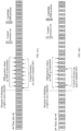
- the candidate SSB positions shown in FIGS. 3(a) and 3(b) are marked with a serial number of the SSB position. SSB positions with the serial same number can be used to send SSBs with QCL relationship.
- the positions with different serial numbers correspond to SSBs with different indexes, where each candidate SSB position is used to send the corresponding SSB.
- SSB position 0 corresponds to SSB#0. Therefore, each SSB position 0 is used to send SSB#0, or in other words, the SSB sent at SSB position 0 has a QCL relationship.
- SSB position 1 corresponds to SSB#1. Therefore, each SSB position 1 is used to send SSB#1, or in other words, the SSB sent on SSB position 1 has a QCL relationship.
- SSB position 2 corresponds to SSB#2.
- each SSB position 2 is used to send SSB#2, or in other words, the SSB sent at SSB position 2 has a QCL relationship.
- SSB position 3, SSB position 4, SSB position 5, SSB position 6, and SSB position 7 correspond to SSB#3, SSB#4, SSB#5, SSB#6, and SSB#7, respectively.
- Such correspondence may be agreed by a protocol or configured by the network device.
- Each SSB is only sent at its corresponding SSB position. Among them, #0 to #7 represent SSB indexes.
- control resource sets can be selected from the control resource sets with the right to use the channel to transmit the first downlink control information.
- the control resource set that obtains the right to use the channel is also referred to as "useable control resource set", which corresponds to "control resource set transmitting DCI” in the following figures.
- the SSB position that obtains the right to use the channel is also referred to as “usable SSB position", which corresponds to the "SSB position transmitting SSB” in the following figures.
- the network device may select the first control resource set from the control resource sets capable of sending DCI shown in FIGS. 3(a) or 3(b) , and send the first downlink control information in the first control resource set.
- X SSBs can be SSBs to be transmitted by the network device.
- the network device may send X SSBs in the current DRS window, or may send part of the X SSBs in the DRS window.
- the network device can be configured with "11 1 1 1 1 1 1” to mean sending all SSBs, or can be configured with "0 0 0 0 1 1 1” to mean sending SSB#4, SSB#5, SSB#6, SSB# 7.
- the method further includes: the network device sends second downlink control information at a first SSB position corresponding to the first control resource set.
- the terminal device receives the second downlink control information at the first SSB position corresponding to the first control resource set.
- the second downlink control information is used by the terminal device to determine the first control resource set.
- the first SSB position may include one or more SSB positions.
- the second downlink control information sent at the first SSB position may indicate a position of the first control resource set used to send the first downlink control information, for example, indicating a time domain position, a frequency domain position, a search space or other parameters of the first control resource set.
- the second downlink control information may be carried on a Physical Broadcast Channel (PBCH) in an SSB transmitted at the first SSB position.
- PBCH Physical Broadcast Channel
- the PBCH transmitted at the first SSB position carries the second downlink control information.
- the second downlink control information is used to indicate the position of the first control resource set corresponding to the first SSB position.
- the resource of the first control resource set are used to transmit the first downlink control information.
- the first downlink control information indicates the SSB position where the SSB is actually transmitted.
- the network device selects the first SSB position with the right to use the channel, and sends the corresponding first SSB on the first SSB.
- the first SSB includes, for example, PSS, SSS, and PBCH.
- the PBCH may indicate the control resource set used to transmit a Physical Downlink Control Channel (PDCCH).
- the PDCCH transmitted through the resource in the control resource set can be used to transmit the first downlink control information.
- the first downlink control information indicates the SSB position actually transmitting the SSB.
- the PDCCH can also be used to schedule PDSCH, the PDSCH carries RMSI information.
- the PDCCH used to schedule the existing RMSI transmission is used to indicate the SSB position actually transmitting the SSB, thereby reducing the complexity of blindly detecting the PDCCH by the terminal device.
- the first downlink control information may include at least one of the following:
- the terminal device can determine which position have transmitted the SSB.
- the M control resource sets have a one-to-one correspondence with Y SSB positions, and each control resource set corresponds to its adjacent SSB position.
- each of the M control resource sets corresponds to 4 SSB positions, that is, each control resource set corresponds to SSB positions in a time slot.
- the 32 SSB positions are divided into 4 groups of SSB positions (denoted as group 0, group 1, group 2 and group 3). Each group of SSB positions includes SSB position 0 to SSB position 7, which can be used to send SSB#0 to SSB#7, respectively.
- SSB positions with the same number can be used to send SSBs with QCL relationship, where the SSB indexes with QCL relationship can be the same or different, which is not limited in the embodiment of the present application.
- SSB position 0 is used to send SSB#0
- SSB position 1 is used to send SSB#1
- SSB position 2 is used to send SSB#2, and so on.
- the first control resource set can be selected from the control resource sets with the right to use the channel to transmit the first downlink control information.
- the first downlink control information may include 5 bits, where 2 bits (for example, the first 2 bits) are used to indicate in which set of SSB positions the first SSB of the X SSBs is transmitted, the remaining 3 bits are used to indicate the first SSB position where the SSB is transmitted in the group of SSB positions. Taking FIGS. 4(a) and 4(b) as an example, it is assumed that the first downlink control information includes 0 10 10.
- the first downlink control information may include 3 bits. These 3 bits are used to indicate an SSB transmitted at first among the X SSBs, and it is assumed that the first SSB position corresponding to the first control resource set is the SSB position where the SSB is actually transmitted. It is assumed that the first downlink control information includes 0 1 0, it means that the SSB transmitted at first is SSB#2, the corresponding SSB position is SSB position 2, and the first SSB position is SSB position 6 in group 1.
- the terminal device can determine that the SSB position where the SSB is actually transmitted includes SSB#2, SSB#3, SSB#4, SSB#5, SSB#6, SSB#7 in group 1 (the group to which the first SSB position belongs) and SSB#0 and SSB#1 in group 2.
- the first downlink control information may include 3 bits. These 3 bits are used to indicate an SSB transmitted at last among the X SSBs, and it is assumed that the first SSB position corresponding to the first control resource set is the SSB position where the SSB is actually transmitted. It is assumed that the first downlink control information includes 0 0 1, it means that the SSB transmitted at last is SSB#1, the corresponding SSB position is SSB position 1, and the first SSB position is SSB position 6 in group 1.
- the terminal device can determine that the SSB position where the SSB is actually transmitted includes SSB#2, SSB#3, SSB#4, SSB#5, SSB#6, SSB#7 in group 1 (the group to which the first SSB position belongs) and SSB#0 and SSB#1 in group 2.
- the first downlink control information may include 3 bits. These 3 bits are used to indicate a position of the SSB transmitted at the first SSB position corresponding to the first control resource set in the at least one SSB.
- the terminal device can determine that the SSB position where SSB is actually transmitted includes SSB#2, SSB#3, SSB#4, SSB#5, SSB#6, SSB#7 in group 1 (the group to which SSB#6 belongs) and SSB#0 and SSB#1 in group 2.
- the first downlink control information indicates the SSB position where the SSB is actually transmitted, but the present application is not limited to this.
- the first downlink control information can also implicitly or indirectly indicate these SSB positions.
- the first downlink control information may indicate a candidate SSB positions where no SSB is transmitted, or indicate the SSB positions used for other downlink transmissions.
- the first downlink control information includes a bitmap
- the bitmap includes Y bits
- the Y bits have a one-to-one correspondence with the Y SSB positions, where a value on each bit is used to indicate whether a candidate SSB position corresponding to each bit is used to send an SSB.
- the first downlink control information is 00000000 00111111 11000000 00000000, it means SSB#2, SSB#3, SSB#4, SSB#5, SSB#6, SSB#7 in group 1, and SSB#0 and SSB#1 in group 2 have transmitted the corresponding SSBs.
- an unused SSB position can be used for other data transmission to improve resource utilization.
- the method further includes: the network device sends third downlink control information.
- the method further includes: the terminal device receives the third downlink control information.
- the terminal device determines the SSB position where the at least one SSB is transmitted among the Y SSB positions according to the first downlink information and the third downlink control information.
- the third downlink control information is used to determine a time slot structure within a Transmission Opportunity (TXOP) to which a first SSB position corresponding to the first control resource set belongs.
- TXOP Transmission Opportunity
- the M control resource sets have a one-to-one correspondence with Y SSB positions, and each control resource set corresponds to a subsequent adjacent SSB position.
- the candidate SSB positions configured by the network device are located in time slot n+4 to time slot n+7, and each SSB candidate position corresponds to a control resource set.
- the third control information can indicate uplink and downlink transmission conditions in time slot n to time slot n+7. For example, it indicates an end position of a downlink subframe. As shown in FIG. 5(b) , when the terminal device receives the third control information, it can determine, according to the third control information, that time slot n to time slot n+4 are configured for downlink transmission, while the time slots n+5 to time slot n+7 are configured for uplink transmission.
- SFI Slot Frame Indication
- the terminal device can determine that the SSB position where the SSB is actually transmitted is 4 SSB positions in time slot n+4, and the network device sends corresponding SSBs at the 4 SSB positions in the time slot n+4, respectively.
- FIG. 6 is a flow interaction diagram of a method 600 for transmitting downlink control information according to another embodiment of the present application.
- the method described in FIG. 6 can be executed by a network device and a terminal device.
- the terminal device may be, for example, the terminal device 120 shown in FIG. 1 .
- the network device may be, for example, the network device 110 shown in FIG. 1 .
- the method 600 for transmitting downlink control information may include some or all of the following steps.
- the network device determines a first SSB position used by the network device among Y candidate SSB positions on an unlicensed carrier.
- the network device sends a first SSB at the first SSB position.
- a Remaining Minimum System Information (RMSI) corresponding to a PBCH in the first SSB includes first downlink information.
- the first downlink information is used to indicate an SSB position where at least one SSB in X SSBs is sent among the Y SSB positions.
- the terminal device receives the first SSB at the first SSB position among the Y candidate SSB positions on the unlicensed carrier.
- the terminal device determines the SSB position where the at least one SSB in the X SSB positions is transmitted among the Y SSB positions.
- Y and X are both positive integers, and 1 ⁇ X ⁇ Y.
- the network device selects the first SSB position with the right to use the channel, and sends the first SSB on the first SSB.
- the first SSB includes, for example, a Primary Synchronization Signal (PSS), a Secondary Synchronization Signal (SSS), a PBCH, and so on.
- the PBCH can indicate the control resource set used to transmit PDCCH, and the PDCCH transmitted through a resource in the control resource set can be used to schedule PDSCH.
- the PDSCH carries RMSI information, and the RMSI information is the RMSI information corresponding to the PBCH.
- the RMSI information includes first downlink information, and the first downlink information indicates an SSB position where at least one SSB is transmitted among the Y SSB positions. According to the RMSI corresponding to the PBCH in the first SSB, the terminal device can obtain the SSB position where the SSB is actually transmitted.
- the existing RMSI is used to indicate the SSB position where the SSB is actually transmitted, which saves the signaling overhead of the downlink control information transmitted on the PDCCH.
- the first downlink information includes at least one of the following information: an SSB position where the at least one SSB is transmitted among the Y SSB positions; a first SSB position where an SSB is transmitted among the Y SSB positions; a last SSB position where an SSB is transmitted among the Y SSB positions; an index of an SSB transmitted at first among the Y SSB positions; an index of an SSB transmitted at last among the Y SSB positions; a position of the SSB transmitted at first in the at least one SSB among the X SSBs among the Y SSB positions; a position of the SSB transmitted at last in the at least one SSB among the X SSBs among the Y SSB positions; and a position of an SSB, which is transmitted at a first SSB position corresponding to the first control resource set, in the at least one SSB among the X SSBs.
- the first downlink information includes a bitmap
- the bitmap includes Y bits
- the Y bits have a one-to-one correspondence with the Y SSB positions, where a value on each bit is used to indicate whether a candidate SSB position corresponding to each bit is used to send an SSB.
- the first downlink control information indicates the SSB position where at least one SSB in the X SSBs is transmitted in the Y candidate SSB positions may make reference to the above related description of the method 200. For brevity, the details are not described herein again.
- the method further includes: the network device sends third downlink control information.
- the method further includes: the terminal device receives the third downlink control information; where in 640, the terminal device determines the SSB position where the at least one SSB is transmitted among the Y SSB positions according to the first downlink information and the third downlink control information.
- the third downlink control information is used to determine a time slot structure within a TXOP to which the first SSB position belongs.
- the third control information may be, for example, SFI information, which is used to indicate the time slot structure within the TXOP to which the first SSB position belongs, that is, uplink and downlink transmission conditions in the TXOP.
- the network device may send the first downlink information in a time slot configured with a downlink transmission. For details, please refer to the above description of FIGS. 5(a) and 5(b) , which will not be repeated here.
- sequence numbers of the above processes do not imply a sequence of executions, and the execution order of the processes should be determined by their functions and an internal logic, and should not constitute any limitation on the implementation process of the embodiments of the present application.
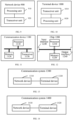
- FIG. 7 is a schematic block diagram of a network device 700 according to an embodiment of the present application.
- the network device 700 includes a processing unit 710 and a transceiver unit 720, where:
- the network device can flexibly indicate the actual position where the SSB is transmitted within the DRS transmission window through the downlink control information, so that the terminal device can obtain the transmission position of the SSB according to the downlink control information, and thereby performing the rate matching of the downlink data reception, and realizing the effective use of SSB.
- M ⁇ Y, the M control resource sets include a second control resource set, and the second control resource set corresponds to at least two SSB positions.
- the at least two SSB positions correspond to the second control resource set are located in a same time unit.
- M Y
- the M control resource sets have a one-to-one correspondence with the Y SSB positions.
- a correspondence between the M control resource sets and the Y SSB positions is preset, or configured by the network device.
- the transceiver unit 720 is further configured to: send second downlink control information at a first SSB position corresponding to the first control resource set, where the second downlink control information is used to determine the first control resource set.
- the second downlink control information is carried on a physical broadcast channel PBCH in an SSB transmitted at the first SSB position.
- the first downlink control information includes at least one of the following information: an SSB position where the at least one SSB is transmitted among the Y SSB positions; a first SSB position where an SSB is transmitted among the Y SSB positions; a last SSB position where an SSB is transmitted among the Y SSB positions; an index of an SSB transmitted at first among the Y SSB positions; an index of an SSB transmitted at last among the Y SSB positions; a position of the SSB transmitted at first in the at least one SSB among the Y SSB positions; a position of the SSB transmitted at last in the at least one SSB among the Y SSB positions; and a position of an SSB, which is transmitted at a first SSB position corresponding to the first control resource set, in the at least one SSB.
- the first downlink control information includes a bitmap
- the bitmap includes Y bits
- the Y bits have a one-to-one correspondence with the Y SSB positions, where a value on each bit is used to indicate whether a candidate SSB position corresponding to each bit is used to send an SSB.
- the transceiver unit 720 is further configured to: send third downlink control information, where the third downlink control information is used to determine a time slot structure within a transmission opportunity TXOP to which a first SSB position corresponding to the first control resource set belongs.
- the network device 700 can perform the corresponding operations performed by the network device in the above method 200. For the sake of brevity, details are not described herein again.
- FIG. 8 is a schematic block diagram of a terminal device 800 according to an embodiment of the present application.
- the terminal device 800 includes a transceiver unit 810 and a processing unit 820, where:
- the network device can flexibly indicate the actual position where the SSB is transmitted within the DRS transmission window through the downlink control information, so that the terminal device can obtain the transmission position of the SSB according to the downlink control information, and thereby performing the rate matching of the downlink data reception, and realizing the effective use of SSB.
- M ⁇ Y, the M control resource sets include a second control resource set, and the second control resource set corresponds to at least two SSB positions.
- the at least two SSB positions corresponding to the second control resource set are located in a same time unit.
- M Y
- the M control resource sets have a one-to-one correspondence with the Y SSB positions.
- a correspondence between the M control resource sets and the Y SSB positions is preset, or configured by the network device.
- the transceiver unit 810 is further configured to: receive second downlink control information at a first SSB position corresponding to the first control resource set, where the second downlink control information is used to determine the first control resource set.
- the second downlink control information is carried on a physical broadcast channel PBCH in an SSB transmitted at the first SSB position.
- the first downlink control information includes at least one of the following information: an SSB position where the at least one SSB is transmitted among the Y SSB positions; a first SSB position where an SSB is transmitted among the Y SSB positions; a last SSB position where an SSB is transmitted among the Y SSB positions; an index of an SSB transmitted at first among the Y SSB positions; an index of an SSB transmitted at last among the Y SSB positions; a position of the SSB transmitted at first in the at least one SSB among the Y SSB positions; a position of the SSB transmitted at last in the at least one SSB among the Y SSB positions; and a position of an SSB, which is transmitted at a first SSB position corresponding to the first control resource set, in the at least one SSB.
- the first downlink control information includes a bitmap
- the bitmap includes Y bits
- the Y bits have a one-to-one correspondence with the Y SSB positions, where a value on each bit is used to indicate whether a candidate SSB position corresponding to each bit is used to transmit an SSB.
- the transceiver unit 810 is further configured to: receive third downlink control information, where the third downlink control information is used to determine a time slot structure within a transmission opportunity TXOP to which a first SSB position corresponding to the first control resource set belongs; the processing unit 820 is specifically configured to: determine the SSB position where the at least one SSB is transmitted among the Y SSB positions according to the first downlink control information and the third downlink control information.
- terminal device 800 can perform the corresponding operations performed by the terminal device in the above method 200. For the sake of brevity, details are not described herein again.
- FIG. 9 is a schematic block diagram of a network device 900 according to another embodiment of the present application.
- the network device 900 includes a processing unit 910 and a transceiver unit 920, where:
- the existing RMSI is used to indicate the SSB position where the SSB is actually transmitted, which saves signaling overhead.
- the first downlink information includes at least one of the following information: an SSB position where the at least one SSB is transmitted among the Y SSB positions; a first SSB position where an SSB is transmitted among the Y SSB positions; a last SSB position where an SSB is transmitted among the Y SSB positions; an index of an SSB transmitted at first among the Y SSB positions; an index of an SSB transmitted at last among the Y SSB positions; a position of the SSB transmitted at first in the at least one SSB among the Y SSB positions; a position of the SSB transmitted at last in the at least one SSB among the Y SSB positions; and a position of an SSB, which is transmitted at the first SSB position, in the at least one SSB.
- the first downlink information includes a bitmap
- the bitmap includes Y bits
- the Y bits have a one-to-one correspondence with the Y SSB positions, where a value on each bit is used to indicate whether a candidate SSB position corresponding to each bit is used to send an SSB.
- the transceiver unit 920 is further configured to: send third downlink control information, where the third downlink control information is used to determine a time slot structure within a transmission opportunity TXOP to which the first SSB position belongs.
- the network device 900 can perform the corresponding operations performed by the network device in the above method 600. For the sake of brevity, details are not described herein again.
- FIG. 10 is a schematic block diagram of a terminal device 1000 according to another embodiment of the present application.
- the terminal device 1000 includes a transceiver unit 1010 and a processing unit 1020, where:
- the existing RMSI is used to indicate the SSB position where the SSB is actually transmitted, which saves signaling overhead.
- the first downlink information includes at least one of the following information: an SSB position where the at least one SSB is transmitted among the Y SSB positions; a first SSB position where an SSB is transmitted among the Y SSB positions; a last SSB position where an SSB is transmitted among the Y SSB positions; an index of an SSB transmitted at first among the Y SSB positions; an index of an SSB transmitted at last among the Y SSB positions; a position of the SSB transmitted at first in the at least one SSB among the Y SSB positions; a position of the SSB transmitted at last in the at least one SSB among the Y SSB positions; and a position of an SSB, which is transmitted at the first SSB position, in the at least one SSB.
- the first downlink information includes a bitmap
- the bitmap includes Y bits
- the Y bits have a one-to-one correspondence with the Y SSB positions, where a value on each bit is used to indicate whether a candidate SSB position corresponding to each bit is used to transmit an SSB.
- the transceiver unit 1010 is further configured to: receive third downlink control information, where the third downlink control information is used to determine a time slot structure within a transmission opportunity TXOP to which the first SSB position belongs; the processing unit 1020 is specifically configured to: determine the SSB position where the at least one SSB is transmitted among the Y SSB positions according to the first downlink information and the third downlink control information.
- terminal device 1000 can perform the corresponding operations performed by the terminal device in the above method 600. For the sake of brevity, details are not described herein again.
- FIG. 11 is a schematic structural diagram of a communication device 1100 according to an embodiment of the present application.
- the communication device may be a terminal.
- the communication device 1100 shown in FIG. 11 includes a processor 1110 which can call and run a computer program from the memory to implement the methods in embodiments of the present application.
- the communication device 1100 may further include a memory 1120.
- the processor 1110 can call and run a computer program from the memory 1120 to implement the methods in embodiments of the present application.
- the memory 1120 may be a separate device independent of the processor 1110 or may be integrated in the processor 1110.
- the communication device 1100 may further include a transceiver 1130, and the processor 1110 can control the transceiver 1130 to communicate with other devices and, in particular, may control the transceiver 1130 to send/receive information or data to/from other devices.
- the processor 1110 can control the transceiver 1130 to communicate with other devices and, in particular, may control the transceiver 1130 to send/receive information or data to/from other devices.
- the transceiver 1130 may include a transmitter and a receiver.
- the transceiver 1130 may further include an antenna, and the number of the antenna may be one or more.
- the communication device 1100 may specifically be the network device in any embodiment of the present application, and the communication device 1100 can implement corresponding processes implemented by the network device in the methods of the embodiments of the present application, which, for conciseness, will not be repeated herein.
- the communication device 1100 may specifically be the terminal device in the embodiments of the present application, and the communication device 1100 can implement corresponding processes implemented by the terminal device in the methods of the embodiments of the present application, which, for the sake of conciseness, will not be repeated herein.
- FIG. 12 is a schematic structural diagram of a chip according to an embodiment of the present application.
- the chip 1200 shown in FIG. 12 includes a processor 1210 which can call and run a computer program from a memory to implement the methods in embodiments of the present application.
- the chip 1200 may further include a memory 1220.
- the processor 1210 can call and run a computer program from the memory 1220 to implement the methods in embodiments of the present application.
- the memory 1220 may be a separate device independent of the processor 1210 or may be integrated in the processor 1210.
- the chip 1200 may also include an input interface 1230.
- the processor 1210 can control the input interface 1230 to communicate with other devices or chips. Specifically, information or data sent by other devices or chips can be acquired.
- the chip 1200 may also include an output interface 1240.
- the processor 1210 can control the output interface 1240 to communicate with other devices or chips. Specifically, information or data can be output to other devices or chips.
- the chip can be applied to the network device in any embodiment of the present application, and the chip can implement corresponding processes implemented by the network device in the methods in the embodiments of the present application, which, for the sake of conciseness, will not be repeated herein.
- the chip can be applied to the terminal device in the embodiments of the present application, and the chip can implement corresponding processes implemented by the terminal device in the methods of the embodiments of the present application, which, for the sake of conciseness, will not be repeated herein.
- the chip mentioned in the embodiment of the present application may also be referred to as a system level chip, a system chip, a chip system or a system on chip, or the like.
- a processor in an embodiment of the present application may be an integrated circuitry chip capable of processing a signal.
- each step of the above method embodiments may be accomplished by an integrated logic circuit of hardware in a processor, or instructions in the form of software.
- the processor may be a general-purpose processor, a digital signal processor (DSP), an application specific integrated circuit (ASIC), a field programmable gate array (FPGA), or other programmable logic devices, discrete gates or transistor logic devices or discrete hardware components.
- DSP digital signal processor
- ASIC application specific integrated circuit
- FPGA field programmable gate array
- the methods, steps, and logical block diagrams disclosed in the embodiments of the present application can be implemented or executed.
- the general purpose processor may be a microprocessor, or the processor may also be any conventional processor or the like.
- the steps of the method disclosed with reference to the embodiments of the present application may be directly embodied as being accomplished by the execution of the hardware decoding processor or by a combination of hardware and software modules in the processor.
- the software module may be located in a storage medium readily available in the art, such as a random access memory, a flash memory, a read only memory, a programmable read only memory or an electrically erasable programmable memory, a register, or the like.
- the storage medium is located in the memory.
- the processor reads information in the memory and accomplishes the steps of the above methods in combination with the hardware.
- the memory in the embodiments of the present application may be a volatile memory or a non-volatile memory, or may include both volatile and non-volatile memories.
- the non-volatile memory may be a read-only memory (ROM), a programmable ROM (PROM), an erasable PROM (EPROM), an electrically EPROM (EEPROM) or a flash memory.
- the volatile memory can be a random access memory (RAM) that acts as an external cache.
- RAM of many forms are available, such as a static RAM (SRAM), a dynamic RAM (DRAM), a synchronous DRAM (SDRAM), a double data rate SDRAM (DDR SDRAM), an enhanced SDRAM (ESDRAM), a synchlink DRAM (SLDRAM) and a direct rambus RAM (DR RAM).
- SRAM static RAM
- DRAM dynamic RAM
- SDRAM synchronous DRAM
- DDR SDRAM double data rate SDRAM
- ESDRAM enhanced SDRAM
- SLDRAM synchlink DRAM
- DR RAM direct rambus RAM
- the memory in the embodiments of the present application may also be a static RAM (SRAM), a dynamic RAM (DRAM), a synchronous DRAM (SDRAM), a double data rate SDRAM (DDR SDRAM), an enhanced SDRAM (ESDRAM), a synchlink DRAM (SLDRAM), a direct rambus RAM (DR RAM), or the like. That is, the memories in the embodiments of the present application are intended to include, rather than being limited to, these and any other suitable types of memories.
- SRAM static RAM
- DRAM dynamic RAM
- SDRAM synchronous DRAM
- DDR SDRAM double data rate SDRAM
- ESDRAM enhanced SDRAM
- SLDRAM synchlink DRAM
- DR RAM direct rambus RAM
- FIG. 13 is a schematic block diagram of a communication system 1300 according to an embodiment of the present application. As shown in FIG. 13 , the communication system 1300 includes a network device 1310 and a terminal device 1320,
- the network device 1310 can be configured to implement the corresponding functions implemented by the network device in the above method 200, and the composition of the network device 1310 can be as shown in the network device 700 in FIG. 7 . For the sake of brevity, details are not described herein again.
- the terminal device 1320 can be configured to implement the corresponding functions implemented by the terminal device in the above method 200, and the composition of the terminal device 1320 can be as shown in the terminal device 800 in FIG. 8 . For the sake of brevity, details are not described herein again.
- FIG. 14 is a schematic block diagram of a communication system 1400 according to an embodiment of the present application.
- the communication system 1400 includes a network device 1410 and a terminal device 1420, where:
- the network device 1410 can be used to implement the corresponding functions implemented by the network device in the above method 600, and the composition of the network device 1410 can be as shown in the network device 900 in FIG. 9 . For the sake of brevity, details are not described herein again.
- the terminal device 1420 can be used to implement the corresponding functions implemented by the terminal device in the above method 600, and the composition of the terminal device 1420 can be as shown in the terminal device 1000 in FIG. 10 . For the sake of brevity, details are not described herein again.
- a computer readable storage medium is also provided by an embodiment of the present application for storing a computer program.
- the computer readable storage medium can be applied to the network device in the embodiments of the present application, and the computer program enables a computer to implement corresponding processes implemented by the network device in the methods in the embodiments of the present application, which, for the sake of conciseness, will not be repeated herein.
- the computer readable storage medium can be applied to the terminal device in the embodiments of the present application, and the computer program enables a computer to implement corresponding processes implemented by the terminal device in the methods in the embodiments of the present application, which, for the sake of conciseness, will not be repeated herein.
- a computer program product is also provided by an embodiment of the present application, including computer program instructions.
- the computer program product can be applied to the network device in the embodiments of the present application, and the computer program instructions enable a computer to implement corresponding processes implemented by the network device in the methods in the embodiments of the present application, which, for the sake of conciseness, will not be repeated herein.
- the computer program product can be applied to the terminal device in the embodiments of the present application, and the computer program instructions enable a computer to implement corresponding processes implemented by the terminal device in the methods in the embodiments of the present application, which, for the sake of conciseness, will not be repeated herein.
- a computer program is also provided by an embodiment of the present application.
- the computer program can be applied to the network device in the embodiments of the present application, and the computer program, when executed on a computer, enables the computer to implement corresponding processes implemented by the network device in the methods in the embodiments of the present application, which, for the sake of conciseness, will not be repeated herein.
- the computer program can be applied to the terminal device in the embodiments of the present application, and the computer program, when executed on a computer, enables the computer to implement corresponding processes implemented by the terminal device in the methods in the embodiments of the present application, which, for the sake of conciseness, will not be repeated herein.
- system and “network” may be used interchangeably.
- and/or merely describes a relation between related objects, representing three possible relations. For instance, A and/or B may represent three cases: A alone, A and B together, and B alone. Additionally, as used herein, the symbol “/” typically means the related objects before and after the symbol are in a "or” relation.
- B corresponding to A indicates that B is associated with A, and B may be determined according to A.
- determining B according to A does not mean that B is only determined according to A, but that B may also be determined based on A and/or other information.
- the units described as separate components may be or may not be physically separated, and the components displayed as units may be or may not be physical units, that is, they may be located in one place, or may be distributed onto multiple network units. Some or all of the units may be selected according to actual needs to implement the purpose of the solution of the present embodiment.
- each functional unit in the embodiments of the present application may be integrated into one processing unit, or each unit may physically exist independently, or two or more of the above units may be integrated into one unit.
- the functions may be stored in a computer readable storage medium if they are implemented in the form of a software functional unit, and sold or used as a standalone product.
- the technical solution of the present application in essence, or the part contributing to the existing technology or the part of the technical solution may be embodied in the form of a software product, and the computer software product is stored in a storage medium and includes several instructions for enabling a computer device (which may be a personal computer, a server, or a network device, or the like) to perform all or part of the steps described in methods in the embodiments of the present application.
- the above storage medium includes various media that may store program codes, such as a U disk, a mobile hard disk, a read-only memory (ROM), a random access memory (RAM), a magnetic disk, or an optical disk.
Landscapes
- Engineering & Computer Science (AREA)
- Signal Processing (AREA)
- Computer Networks & Wireless Communication (AREA)
- Mobile Radio Communication Systems (AREA)
Claims (15)
- Verfahren zur Übertragung von Downlink-Steuerungsinformationen, umfassend:Bestimmen (210), durch eine Netzvorrichtung, eines ersten Steuerressourcensatzes, der in der Lage ist, von der Netzvorrichtung aus M Steuerressourcensätzen verwendet zu werden, wobei die M Steuerressourcensätze Y potenziellen Synchronisationssignalblock (SSB)-Positionen auf einem unlizenzierten Träger entsprechen; undSenden (220), durch die Netzvorrichtung, von ersten Downlink-Steuerungsinformationen auf einer Ressource des ersten Steuerressourcensatzes, wobei die ersten Downlink-Steuerungsinformationen verwendet werden, um eine SSB-Position zu bestimmen, wobei wenigstens ein SSB in X SSBs aus den Y SSB-Positionen gesendet wird, wobei M, Y und X alle positive Ganzzahlen sind, und 1≤X<Y, M≤Y ist.
- Verfahren gemäß Anspruch 1, wobei, wenn M<Y ist, die M Steuerressourcensätze einen zweiten Steuerressourcensatz umfassen, wobei der zweite Steuerressourcensatz wenigstens zwei SSB-Positionen entspricht und sich die wenigstens zwei SSB-Positionen entsprechend dem zweiten Steuerressourcensatz in derselben Zeiteinheit befinden; und
wenn M=Y ist, die M Steuerressourcensätze eine Eins-zu-Eins-Entsprechung mit den Y SSB-Positionen haben. - Verfahren gemäß Anspruch 1 oder 2, ferner umfassend:
Senden, durch die Netzvorrichtung, von zweiten Downlink-Steuerungsinformationen an einer ersten SSB-Position entsprechend dem ersten Steuerressourcensatz, wobei die zweiten Downlink-Steuerungsinformationen verwendet werden, um den ersten Steuerressourcensatz zu bestimmen, wobei die zweiten Downlink-Steuerungsinformationen auf einem physischen Rundsendekanal (Physical Broadcast Channel, PBCH) transportiert werden, in einem SSB, der an der ersten SSB-Position übertragen wird. - Verfahren gemäß einem der Ansprüche 1 bis 3, wobei die ersten Downlink-Steuerungsinformationen wenigstens eine der folgenden Informationen umfassen:eine SSB-Position, an der der wenigstens eine SSB aus den Y SSB-Positionen übertragen wird;eine erste SSB-Position, die verwendet wird, um einen SSB aus den Y SSB-Positionen zu übertragen;eine letzte SSB-Position, die verwendet wird, um einen SSB aus den Y SSB-Positionen zu übertragen;einen Index eines SSB, der zuerst aus den Y SSB-Positionen übertragen wird;einen Index eines SSB, der zuletzt aus den Y SSB-Positionen übertragen wird;eine Position des SSB, der zuerst in dem wenigstens einen SSB aus den Y SSB-Positionen übertragen wird;eine Position des SSB, der zuletzt in dem wenigstens einen SSB aus den Y SSB-Positionen übertragen wird; undeine Position eines SSB, der an einer ersten SSB-Position entsprechend dem ersten Steuerressourcensatz in dem wenigstens einen SSB übertragen wird.
- Verfahren gemäß einem der Ansprüche 1 bis 3, wobei die ersten Downlink-Steuerungsinformationen eine Bitmap umfassen, wobei die Bitmap Y Bits umfasst und die Y Bits eine Eins-zu-Eins-Entsprechung mit den Y SSB-Positionen haben, wobei ein Wert in jedem Bit verwendet wird, um anzugeben, ob eine potenzielle SSB-Position entsprechend jedem Bit verwendet wird, um einen SSB zu senden.
- Verfahren gemäß einem der Ansprüche 1 bis 5, ferner umfassend:
Senden, durch die Netzvorrichtung, von dritten Downlink-Steuerungsinformationen, wobei die dritten Downlink-Steuerungsinformationen verwendet werden, um eine Zeitschlitzstruktur innerhalb einer Übertragungsgelegenheit (Transmission Opportunity, TXOP), zu bestimmen, zu der eine erste SSB-Position entsprechend dem ersten Steuerressourcensatz gehört. - Verfahren zum Empfangen von Downlink-Steuerungsinformationen, umfassend:Empfangen (230), durch eine Endgerätevorrichtung, von ersten Downlink-Steuerungsinformationen auf einer Ressource eines ersten Steuerressourcensatzes in M Steuerressourcensätzen, wobei die M Steuerressourcensätze Y potenziellen Synchronisationssignalblock (SSB)-Positionen auf einem unlizenzierten Träger entsprechen; undBestimmen (240), durch die Endgerätevorrichtung, gemäß den ersten Downlink-Steuerungsinformationen, einer SSB-Position, an der wenigstens ein SSB in X SSBs aus den Y SSB-Positionen übertragen wird, wobei M, Y und X alle positive Ganzzahlen sind und 1≤X<Y, M≤Y ist.
- Verfahren gemäß Anspruch 7, wobei, wenn M<Y ist, die M Steuerressourcensätze einen zweiten Steuerressourcensatz umfassen, wobei der zweite Steuerressourcensatz wenigstens zwei SSB-Positionen entspricht und sich die wenigstens zwei SSB-Positionen entsprechend dem zweiten Steuerressourcensatz in derselben Zeiteinheit befinden; und
wenn M=Y ist, die M Steuerressourcensätze eine Eins-zu-Eins-Entsprechung mit den Y SSB-Positionen haben. - Verfahren gemäß Anspruch 7 oder 8, wobei eine Entsprechung zwischen den M Steuerressourcensätzen und den Y SSB-Positionen voreingestellt oder durch die Netzvorrichtung konfiguriert ist.
- Verfahren gemäß einem der Ansprüche 7 bis 9, ferner umfassend:
Empfangen, durch die Endgerätevorrichtung, von zweiten Downlink-Steuerungsinformationen an einer ersten SSB-Position entsprechend dem ersten Steuerressourcensatz, wobei die zweiten Downlink-Steuerungsinformationen verwendet werden, um den ersten Steuerressourcensatz zu bestimmen, wobei die zweiten Downlink-Steuerungsinformationen auf einem physischen Rundsendekanal (Physical Broadcast Channel, PBCH) transportiert werden, in einem SSB, der an der ersten SSB-Position übertragen wird. - Verfahren gemäß einem der Ansprüche 7 bis 10, wobei die ersten Downlink-Steuerungsinformationen wenigstens eine der folgenden Informationen umfassen:eine SSB-Position, an der der wenigstens eine SSB aus den Y SSB-Positionen übertragen wird;eine erste SSB-Position, an der ein SSB aus den Y SSB-Positionen übertragen wird;eine letzte SSB-Position, an der ein SSB aus den Y SSB-Positionen übertragen wird;einen Index eines SSB, der zuerst aus den Y SSB-Positionen übertragen wird;einen Index eines SSB, der zuletzt aus den Y SSB-Positionen übertragen wird;eine Position des SSB, der zuerst in dem wenigstens einen SSB aus den Y SSB-Positionen übertragen wird;eine Position des SSB, der zuletzt in dem wenigstens einen SSB aus den Y SSB-Positionen übertragen wird; undeine Position eines SSB, der an einer ersten SSB-Position entsprechend dem ersten Steuerressourcensatz in dem wenigstens einen SSB übertragen wird.
- Verfahren gemäß einem der Ansprüche 7 bis 10, wobei die ersten Downlink-Steuerungsinformationen eine Bitmap umfassen, wobei die Bitmap Y Bits umfasst und die Y Bits eine Eins-zu-Eins-Entsprechung mit den Y SSB-Positionen haben, wobei ein Wert in jedem Bit verwendet wird, um anzugeben, ob eine potenzielle SSB-Position entsprechend jedem Bit verwendet wird, um einen SSB zu übertragen.
- Verfahren gemäß einem der Ansprüche 7 bis 12, ferner umfassend:Empfangen, durch die Endgerätevorrichtung, von dritten Downlink-Steuerungsinformationen, wobei die dritten Downlink-Steuerungsinformationen verwendet werden, um eine Zeitschlitzstruktur innerhalb einer Übertragungsgelegenheit (Transmission Opportunity, TXOP), zu bestimmen, zu der eine erste SSB-Position entsprechend dem ersten Steuerressourcensatz gehört;wobei das Bestimmen (240), durch die Endgerätevorrichtung, gemäß den ersten Downlink-Steuerungsinformationen, einer SSB-Position, an der wenigstens ein SSB in X SSBs aus den Y SSB-Positionen übertragen wird, umfasst:
Bestimmen, durch die Endgerätevorrichtung, der SSB-Position, an der der wenigstens ein SSB aus den Y SSB-Positionen gemäß den ersten Downlink-Steuerungsinformationen und den dritten Downlink-Steuerungsinformationen übertragen wird. - Netzvorrichtung, umfassend einen Prozessor und einen Speicher,
wobei der Speicher dafür ausgelegt ist, ein Computerprogramm zu speichern, und der Prozessor dafür ausgelegt ist, das im Speicher gespeicherte Computerprogramm aufzurufen und auszuführen, um das Verfahren gemäß einem der Ansprüche 1 bis 6 durchzuführen. - Endgerätevorrichtung, umfassend einen Prozessor und einen Speicher,
wobei der Speicher dafür ausgelegt ist, ein Computerprogramm zu speichern, und der Prozessor dafür ausgelegt ist, das im Speicher gespeicherte Computerprogramm aufzurufen und auszuführen, um das Verfahren gemäß einem der Ansprüche 7 bis 13 durchzuführen.
Applications Claiming Priority (1)
| Application Number | Priority Date | Filing Date | Title |
|---|---|---|---|
| PCT/CN2018/113831 WO2020087541A1 (zh) | 2018-11-02 | 2018-11-02 | 下行控制信息的传输方法和设备 |
Publications (3)
| Publication Number | Publication Date |
|---|---|
| EP3876459A1 EP3876459A1 (de) | 2021-09-08 |
| EP3876459A4 EP3876459A4 (de) | 2021-12-08 |
| EP3876459B1 true EP3876459B1 (de) | 2023-10-25 |
Family
ID=70463581
Family Applications (1)
| Application Number | Title | Priority Date | Filing Date |
|---|---|---|---|
| EP18938553.7A Active EP3876459B1 (de) | 2018-11-02 | 2018-11-02 | Verfahren und system zur übertragung von downlink-steuerungsinformationen |
Country Status (4)
| Country | Link |
|---|---|
| US (1) | US11856539B2 (de) |
| EP (1) | EP3876459B1 (de) |
| CN (1) | CN113039738A (de) |
| WO (1) | WO2020087541A1 (de) |
Families Citing this family (1)
| Publication number | Priority date | Publication date | Assignee | Title |
|---|---|---|---|---|
| US11751150B2 (en) * | 2020-02-19 | 2023-09-05 | Qualcomm Incorporated | Synchronization signal block indexing schemes |
Family Cites Families (11)
| Publication number | Priority date | Publication date | Assignee | Title |
|---|---|---|---|---|
| US20200205095A1 (en) * | 2017-03-23 | 2020-06-25 | Telefonaktiebolaget Lm Ericsson (Publ) | Network node, wireless communication device, methods and computer programs |
| CN110463327A (zh) * | 2017-04-03 | 2019-11-15 | 瑞典爱立信有限公司 | 在无线通信网络中信令发送下行链路控制信息 |
| CN117793919A (zh) * | 2017-11-17 | 2024-03-29 | 中兴通讯股份有限公司 | 信息发送、接收方法及装置 |
| KR102620038B1 (ko) * | 2018-01-26 | 2024-01-02 | 미쓰비시덴키 가부시키가이샤 | 정보를 구성하는 방법 및 장치, 시간-주파수 위치를 결정하는 방법 및 장치, 및 기지국 |
| CN110351740A (zh) * | 2018-04-04 | 2019-10-18 | 中兴通讯股份有限公司 | 信号信道的发送方法、基站、存储介质、电子装置 |
| CN108513362B (zh) * | 2018-04-04 | 2022-10-21 | 宇龙计算机通信科技(深圳)有限公司 | 一种信道检测方法、装置及基站 |
| EP3609284B1 (de) * | 2018-08-09 | 2024-05-22 | Comcast Cable Communications, LLC | Kanalauswahl über ein listen-before-talk-verfahren |
| CN112567826B (zh) * | 2018-08-10 | 2024-04-23 | 联想(新加坡)私人有限公司 | 识别同步信号/物理广播信道块时机 |
| US11197294B2 (en) * | 2018-08-17 | 2021-12-07 | Qualcomm Incorporated | Synchronization signal block and remaining minimum system information integration in unlicensed systems |
| US11871451B2 (en) * | 2018-09-27 | 2024-01-09 | Interdigital Patent Holdings, Inc. | Sub-band operations in unlicensed spectrums of new radio |
| CN111148232B (zh) * | 2018-11-02 | 2021-10-22 | 维沃移动通信有限公司 | 信息传输方法及通信设备 |
-
2018
- 2018-11-02 EP EP18938553.7A patent/EP3876459B1/de active Active
- 2018-11-02 CN CN201880099262.4A patent/CN113039738A/zh active Pending
- 2018-11-02 WO PCT/CN2018/113831 patent/WO2020087541A1/zh unknown
-
2021
- 2021-05-03 US US17/306,227 patent/US11856539B2/en active Active
Also Published As
| Publication number | Publication date |
|---|---|
| EP3876459A1 (de) | 2021-09-08 |
| WO2020087541A1 (zh) | 2020-05-07 |
| CN113039738A (zh) | 2021-06-25 |
| EP3876459A4 (de) | 2021-12-08 |
| US11856539B2 (en) | 2023-12-26 |
| US20210258901A1 (en) | 2021-08-19 |
Similar Documents
| Publication | Publication Date | Title |
|---|---|---|
| US10588130B2 (en) | Methods and apparatus for user equipment capability exchange | |
| JP7167250B2 (ja) | 時間周波数リソースの伝送方向を構成するための方法、および装置 | |
| EP3751880A1 (de) | Drahtloses kommunikationsverfahren für unlizenziertes spektrum und vorrichtung | |
| CN111935839B (zh) | 上行信号的发送方法和终端设备 | |
| US20210250883A1 (en) | Method and device for transmitting ssb in an unlicensed spectrum | |
| CN112369093B (zh) | 同步信号块ssb传输方式的确定方法、设备、芯片和介质 | |
| US11765743B2 (en) | Downlink channel receiving method and terminal device | |
| US20210385774A1 (en) | Wireless communication method, terminal device and network device | |
| WO2020150957A1 (zh) | 用于非授权频谱的无线通信方法和设备 | |
| US20220352923A1 (en) | Frequency hopping methods, electronic device, and storage medium | |
| US20220330342A1 (en) | Wireless communication method, terminal device, and network device | |
| EP3780859A1 (de) | Signalübertragungsverfahren und kommunikationsvorrichtung | |
| US11856539B2 (en) | Method and device for transmitting downlink control information | |
| CN112119595B (zh) | 一种信号加扰方法及装置、通信设备 | |
| KR20210095699A (ko) | 데이터 송신 방법 및 디바이스 |
Legal Events
| Date | Code | Title | Description |
|---|---|---|---|
| STAA | Information on the status of an ep patent application or granted ep patent |
Free format text: STATUS: THE INTERNATIONAL PUBLICATION HAS BEEN MADE |
|
| PUAI | Public reference made under article 153(3) epc to a published international application that has entered the european phase |
Free format text: ORIGINAL CODE: 0009012 |
|
| STAA | Information on the status of an ep patent application or granted ep patent |
Free format text: STATUS: REQUEST FOR EXAMINATION WAS MADE |
|
| 17P | Request for examination filed |
Effective date: 20210531 |
|
| AK | Designated contracting states |
Kind code of ref document: A1 Designated state(s): AL AT BE BG CH CY CZ DE DK EE ES FI FR GB GR HR HU IE IS IT LI LT LU LV MC MK MT NL NO PL PT RO RS SE SI SK SM TR |
|
| A4 | Supplementary search report drawn up and despatched |
Effective date: 20211109 |
|
| RIC1 | Information provided on ipc code assigned before grant |
Ipc: H04L 27/00 20060101ALN20211103BHEP Ipc: H04W 72/02 20090101ALI20211103BHEP Ipc: H04L 5/00 20060101AFI20211103BHEP |
|
| DAV | Request for validation of the european patent (deleted) | ||
| DAX | Request for extension of the european patent (deleted) | ||
| GRAP | Despatch of communication of intention to grant a patent |
Free format text: ORIGINAL CODE: EPIDOSNIGR1 |
|
| STAA | Information on the status of an ep patent application or granted ep patent |
Free format text: STATUS: GRANT OF PATENT IS INTENDED |
|
| RIC1 | Information provided on ipc code assigned before grant |
Ipc: H04L 27/00 20060101ALN20230613BHEP Ipc: H04W 72/02 20090101ALI20230613BHEP Ipc: H04L 5/00 20060101AFI20230613BHEP |
|
| INTG | Intention to grant announced |
Effective date: 20230630 |
|
| GRAS | Grant fee paid |
Free format text: ORIGINAL CODE: EPIDOSNIGR3 |
|
| GRAA | (expected) grant |
Free format text: ORIGINAL CODE: 0009210 |
|
| STAA | Information on the status of an ep patent application or granted ep patent |
Free format text: STATUS: THE PATENT HAS BEEN GRANTED |
|
| AK | Designated contracting states |
Kind code of ref document: B1 Designated state(s): AL AT BE BG CH CY CZ DE DK EE ES FI FR GB GR HR HU IE IS IT LI LT LU LV MC MK MT NL NO PL PT RO RS SE SI SK SM TR |
|
| REG | Reference to a national code |
Ref country code: GB Ref legal event code: FG4D |
|
| REG | Reference to a national code |
Ref country code: CH Ref legal event code: EP |
|
| REG | Reference to a national code |
Ref country code: DE Ref legal event code: R096 Ref document number: 602018060222 Country of ref document: DE |
|
| REG | Reference to a national code |
Ref country code: IE Ref legal event code: FG4D |
|
| PGFP | Annual fee paid to national office [announced via postgrant information from national office to epo] |
Ref country code: DE Payment date: 20231122 Year of fee payment: 6 |
|
| REG | Reference to a national code |
Ref country code: LT Ref legal event code: MG9D |
|
| P01 | Opt-out of the competence of the unified patent court (upc) registered |
Effective date: 20240110 |
|
| REG | Reference to a national code |
Ref country code: NL Ref legal event code: MP Effective date: 20231025 |
|
| REG | Reference to a national code |
Ref country code: AT Ref legal event code: MK05 Ref document number: 1625784 Country of ref document: AT Kind code of ref document: T Effective date: 20231025 |
|
| PG25 | Lapsed in a contracting state [announced via postgrant information from national office to epo] |
Ref country code: NL Free format text: LAPSE BECAUSE OF FAILURE TO SUBMIT A TRANSLATION OF THE DESCRIPTION OR TO PAY THE FEE WITHIN THE PRESCRIBED TIME-LIMIT Effective date: 20231025 |
|
| PG25 | Lapsed in a contracting state [announced via postgrant information from national office to epo] |
Ref country code: GR Free format text: LAPSE BECAUSE OF FAILURE TO SUBMIT A TRANSLATION OF THE DESCRIPTION OR TO PAY THE FEE WITHIN THE PRESCRIBED TIME-LIMIT Effective date: 20240126 |
|
| PG25 | Lapsed in a contracting state [announced via postgrant information from national office to epo] |
Ref country code: IS Free format text: LAPSE BECAUSE OF FAILURE TO SUBMIT A TRANSLATION OF THE DESCRIPTION OR TO PAY THE FEE WITHIN THE PRESCRIBED TIME-LIMIT Effective date: 20240225 |
|
| PG25 | Lapsed in a contracting state [announced via postgrant information from national office to epo] |
Ref country code: LT Free format text: LAPSE BECAUSE OF FAILURE TO SUBMIT A TRANSLATION OF THE DESCRIPTION OR TO PAY THE FEE WITHIN THE PRESCRIBED TIME-LIMIT Effective date: 20231025 |
|
| PG25 | Lapsed in a contracting state [announced via postgrant information from national office to epo] |
Ref country code: AT Free format text: LAPSE BECAUSE OF FAILURE TO SUBMIT A TRANSLATION OF THE DESCRIPTION OR TO PAY THE FEE WITHIN THE PRESCRIBED TIME-LIMIT Effective date: 20231025 |
|
| PG25 | Lapsed in a contracting state [announced via postgrant information from national office to epo] |
Ref country code: ES Free format text: LAPSE BECAUSE OF FAILURE TO SUBMIT A TRANSLATION OF THE DESCRIPTION OR TO PAY THE FEE WITHIN THE PRESCRIBED TIME-LIMIT Effective date: 20231025 |
|
| PG25 | Lapsed in a contracting state [announced via postgrant information from national office to epo] |
Ref country code: LT Free format text: LAPSE BECAUSE OF FAILURE TO SUBMIT A TRANSLATION OF THE DESCRIPTION OR TO PAY THE FEE WITHIN THE PRESCRIBED TIME-LIMIT Effective date: 20231025 Ref country code: IS Free format text: LAPSE BECAUSE OF FAILURE TO SUBMIT A TRANSLATION OF THE DESCRIPTION OR TO PAY THE FEE WITHIN THE PRESCRIBED TIME-LIMIT Effective date: 20240225 Ref country code: GR Free format text: LAPSE BECAUSE OF FAILURE TO SUBMIT A TRANSLATION OF THE DESCRIPTION OR TO PAY THE FEE WITHIN THE PRESCRIBED TIME-LIMIT Effective date: 20240126 Ref country code: ES Free format text: LAPSE BECAUSE OF FAILURE TO SUBMIT A TRANSLATION OF THE DESCRIPTION OR TO PAY THE FEE WITHIN THE PRESCRIBED TIME-LIMIT Effective date: 20231025 Ref country code: BG Free format text: LAPSE BECAUSE OF FAILURE TO SUBMIT A TRANSLATION OF THE DESCRIPTION OR TO PAY THE FEE WITHIN THE PRESCRIBED TIME-LIMIT Effective date: 20240125 Ref country code: AT Free format text: LAPSE BECAUSE OF FAILURE TO SUBMIT A TRANSLATION OF THE DESCRIPTION OR TO PAY THE FEE WITHIN THE PRESCRIBED TIME-LIMIT Effective date: 20231025 Ref country code: PT Free format text: LAPSE BECAUSE OF FAILURE TO SUBMIT A TRANSLATION OF THE DESCRIPTION OR TO PAY THE FEE WITHIN THE PRESCRIBED TIME-LIMIT Effective date: 20240226 |