EP3876402B1 - Radnabenantrieb mit hochauflösender sensorik - Google Patents
Radnabenantrieb mit hochauflösender sensorik Download PDFInfo
- Publication number
- EP3876402B1 EP3876402B1 EP21160209.9A EP21160209A EP3876402B1 EP 3876402 B1 EP3876402 B1 EP 3876402B1 EP 21160209 A EP21160209 A EP 21160209A EP 3876402 B1 EP3876402 B1 EP 3876402B1
- Authority
- EP
- European Patent Office
- Prior art keywords
- axle
- wheel hub
- hub drive
- sensor
- wheel
- Prior art date
- Legal status (The legal status is an assumption and is not a legal conclusion. Google has not performed a legal analysis and makes no representation as to the accuracy of the status listed.)
- Active
Links
Images

Classifications
-
- H—ELECTRICITY
- H02—GENERATION; CONVERSION OR DISTRIBUTION OF ELECTRIC POWER
- H02K—DYNAMO-ELECTRIC MACHINES
- H02K11/00—Structural association of dynamo-electric machines with electric components or with devices for shielding, monitoring or protection
- H02K11/20—Structural association of dynamo-electric machines with electric components or with devices for shielding, monitoring or protection for measuring, monitoring, testing, protecting or switching
- H02K11/21—Devices for sensing speed or position, or actuated thereby
- H02K11/215—Magnetic effect devices, e.g. Hall-effect or magneto-resistive elements
-
- B—PERFORMING OPERATIONS; TRANSPORTING
- B60—VEHICLES IN GENERAL
- B60K—ARRANGEMENT OR MOUNTING OF PROPULSION UNITS OR OF TRANSMISSIONS IN VEHICLES; ARRANGEMENT OR MOUNTING OF PLURAL DIVERSE PRIME-MOVERS IN VEHICLES; AUXILIARY DRIVES FOR VEHICLES; INSTRUMENTATION OR DASHBOARDS FOR VEHICLES; ARRANGEMENTS IN CONNECTION WITH COOLING, AIR INTAKE, GAS EXHAUST OR FUEL SUPPLY OF PROPULSION UNITS IN VEHICLES
- B60K7/00—Disposition of motor in, or adjacent to, traction wheel
- B60K7/0007—Disposition of motor in, or adjacent to, traction wheel the motor being electric
-
- H—ELECTRICITY
- H02—GENERATION; CONVERSION OR DISTRIBUTION OF ELECTRIC POWER
- H02K—DYNAMO-ELECTRIC MACHINES
- H02K7/00—Arrangements for handling mechanical energy structurally associated with dynamo-electric machines, e.g. structural association with mechanical driving motors or auxiliary dynamo-electric machines
- H02K7/003—Couplings; Details of shafts
-
- H—ELECTRICITY
- H02—GENERATION; CONVERSION OR DISTRIBUTION OF ELECTRIC POWER
- H02K—DYNAMO-ELECTRIC MACHINES
- H02K7/00—Arrangements for handling mechanical energy structurally associated with dynamo-electric machines, e.g. structural association with mechanical driving motors or auxiliary dynamo-electric machines
- H02K7/14—Structural association with mechanical loads, e.g. with hand-held machine tools or fans
-
- B—PERFORMING OPERATIONS; TRANSPORTING
- B60—VEHICLES IN GENERAL
- B60Y—INDEXING SCHEME RELATING TO ASPECTS CROSS-CUTTING VEHICLE TECHNOLOGY
- B60Y2400/00—Special features of vehicle units
- B60Y2400/30—Sensors
- B60Y2400/303—Speed sensors
- B60Y2400/3032—Wheel speed sensors
-
- H—ELECTRICITY
- H02—GENERATION; CONVERSION OR DISTRIBUTION OF ELECTRIC POWER
- H02K—DYNAMO-ELECTRIC MACHINES
- H02K11/00—Structural association of dynamo-electric machines with electric components or with devices for shielding, monitoring or protection
- H02K11/20—Structural association of dynamo-electric machines with electric components or with devices for shielding, monitoring or protection for measuring, monitoring, testing, protecting or switching
- H02K11/25—Devices for sensing temperature, or actuated thereby
-
- H—ELECTRICITY
- H02—GENERATION; CONVERSION OR DISTRIBUTION OF ELECTRIC POWER
- H02K—DYNAMO-ELECTRIC MACHINES
- H02K7/00—Arrangements for handling mechanical energy structurally associated with dynamo-electric machines, e.g. structural association with mechanical driving motors or auxiliary dynamo-electric machines
- H02K7/08—Structural association with bearings
- H02K7/083—Structural association with bearings radially supporting the rotary shaft at both ends of the rotor
-
- H—ELECTRICITY
- H02—GENERATION; CONVERSION OR DISTRIBUTION OF ELECTRIC POWER
- H02K—DYNAMO-ELECTRIC MACHINES
- H02K7/00—Arrangements for handling mechanical energy structurally associated with dynamo-electric machines, e.g. structural association with mechanical driving motors or auxiliary dynamo-electric machines
- H02K7/08—Structural association with bearings
- H02K7/086—Structural association with bearings radially supporting the rotor around a fixed spindle; radially supporting the rotor directly
Definitions
- the invention relates to an electric wheel hub drive with the features of claim 1.
- the invention relates to a small vehicle with such a wheel hub drive.
- a detection device is designed to detect rotational positions and/or a speed of the rotor.
- the detection device has a first sensor element arranged in the receiving space and rotatable with the rotor and a circuit board arranged in the receiving space with a second sensor element.
- the rotational positions and/or the speed of the rotor can be detected by means of the second sensor element in conjunction with the first sensor element.
- the circuit board is held on the cover element.
- document EN 10 2017 216664 A1 discloses a drive comprising a motor with an inner rotor coupled to a rotating axis.
- the drive also comprises a spindle nut and a spindle.
- the spindle is prevented from rotating thanks to an anti-twist device.
- a sensor unit is placed in an interior of the anti-twist device, with the sensor magnet placed on the inside of the rotating axis.
- Electric wheel hub drives are known from the state of the art.
- Sensor systems are used for their operation, such as in EN 10 2010 045 952 A1 described.
- Such sensor systems require rotating, alternating information areas, e.g. magnets, on a not too small circumference as well as an evaluation system. If the information areas are divided sufficiently finely, a high sensor resolution can be achieved, but at the expense of installation space in the axial and radial directions.
- the document US 2009/033166 A1 discloses a wheel hub drive comprising an axial motor.
- a sensor unit is placed near the stator coils, with the wiring of the sensor passing through an interior of the stationary spindle of the motor.
- Hall sensors As a cost-effective and compact alternative, it is common practice to use Hall sensors to directly query the rotor magnets (working magnets). Such systems are used in hoverboard motors or fans, for example. The resolution is lower here. At low speeds, only a relatively rough control of the motor is possible, which can lead to jerking. This makes gentle starting/braking and holding a position problematic.
- the invention is based on the object of improving the accuracy of a wheel hub drive using simple design means. It is desirable that precise driving maneuvers can be carried out even at low speeds.
- a sensor unit for detecting the rotational position or the speed of the wheel element relative to the axle is arranged in the interior.
- the sensor unit has at least one sensor element with a detection area extending in the axial direction.
- the sensor element detects a sensor element that is arranged on the wheel element in a rotationally fixed manner and faces the sensor unit.
- a sensor unit (wheel sensor unit) is arranged in a protected manner within the axle. This allows a particularly compact axial design to be achieved.
- the axle can be designed as a wheel axle, i.e. as an axle for the wheel element.
- the sensor unit is arranged at the axial end of the axle.
- a sensor element of the sensor unit can be, for example, an (absolute) angular Hall encoder, Hall-effect angle sensor, or a multi-turn encoder.
- the transmitter element is in particular designed and determined such that it can interact with the sensor element.
- the transmitter element faces the sensor unit and is arranged at least partially within the detection range of the sensor element.
- the electric motor has a stator and a rotor.
- the stator is rotationally fixedly coupled to the axle and the rotor is rotationally fixedly coupled to the wheel element.
- the rotor is arranged relative to the stator in particular such that the stator can interact with the stator.
- the stator can surround the axle radially outwards and the rotor can surround the stator radially outwards.
- the wheel element can surround the rotor radially outwards.
- the wheel element can also surround the axle, the stator and/or the rotor at least partially axially.
- the wheel element can surround the axle, particularly at its axial end, in such a way that the axial end of the axle is protected from external influences. This means that, for example, no dirt and/or moisture can get directly into/onto the axial end of the axle.
- the sensor element can advantageously have one or more Hall elements, in particular four Hall elements. With several, in particular four Hall elements, a changing magnetic field can be detected particularly precisely. High-resolution commutation of the electric motor is thus possible and precise starting and/or braking can be achieved.
- the sensor element can be designed as a permanent magnet with a north pole and a south pole that determine the direction of magnetization. This is a structurally simple and robust sensor element.
- the permanent magnet can be designed as a ball, rod or disc magnet.
- the permanent magnet can in particular be magnetized diametrically. In other words, the permanent magnet can be magnetized along its diameter. This enables particularly precise angle measurements. Certain deviations in the arrangement of the sensor element relative to the sensor unit have no negative influence on the detection accuracy.
- the permanent magnet can advantageously be arranged on the wheel element in such a way that its magnetization direction is orthogonal to the axial direction of the axle.
- the magnetization direction runs from the north pole to the south pole. This allows the accuracy of the angle measurement to be further optimized.
- the sensor unit, the sensor element, at least one of the Hall elements and/or the transmitter element can be arranged centered along the axial direction of the axis.
- the sensor unit can expediently comprise a temperature sensor and/or a bus element with an interface for connection to a bus system.
- a bus system can, for example, belong to a small vehicle (bus system of the small vehicle).
- the bus element can be designed as a wired interface or as a wireless interface, e.g. an interface that operates via radio.
- the temperature sensor can be used to measure the temperature. Possible temperature-related fluctuations in the accuracy of the angle measurement can be taken into account. This promotes temperature-independent and temperature-stable operation of the electric wheel hub drive.
- the axle has a radial shoulder at the axial end.
- the sensor unit is located on this shoulder. This means that the sensor unit can be protected within the axle and positioned particularly stably.
- the sensor element can be arranged inside the interior.
- the sensor element is thus also arranged in a protected manner inside the axle.
- the sensor element is also arranged on the wheel element.
- the sensor unit comprises a circuit board.
- the sensor element, the temperature sensor and/or the bus element can be arranged on the circuit board.
- the wheel element can be mounted on the axle by means of one or more rolling bearings.
- a different number of rolling bearings can be selected.
- a higher number of rolling bearings can increase the stability of the wheel element.
- the load during operation ie while the wheel element is rotating, is distributed over the various rolling bearings, so that the load and wear on individual bearings can be reduced.
- the wheel element can be designed as a single-part or multi-part wheel.
- the wheel element can form part of a wheel. This can be a rim, for example.
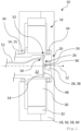
- Figure 1 shows an electric wheel hub drive for a small vehicle, wherein the electric wheel hub drive is designated overall by the reference numeral 10.
- the electric wheel hub drive 10 has an axle 14 that extends along an axial direction 12.
- the axle 14 is designed as a hollow axle 15.
- An electric motor 16 is arranged on the hollow axle 15.
- the electric wheel hub drive 10 further comprises a wheel element 18 which can be driven by the electric motor 16 and which at least partially surrounds the electric motor 16 on the outside.
- the wheel element 18 is rotatably mounted on an axial end 20 of the hollow axle 15.
- axle 14 is designed as a hollow axle 15 in the present case, it is also hollow at the axial end 20 and delimits an interior space 22 radially outward.
- a sensor unit 24 is arranged in the interior 22. This can detect the rotational position, the angle and/or the speed of the wheel element 18 relative to the hollow axle 15.
- the sensor unit 24 has at least one sensor element 26.
- the sensor element 26 has a detection area extending in the axial direction 12.
- the sensor element 26 interacts with a transmitter element 28.
- the transmitter element 28 is rotationally fixed to the wheel element 18. arranged or fixed and facing the sensor unit 26.
- the electric motor 16 has a stator 30 and a rotor 32.
- the stator 30 is coupled to the hollow axle 15 in a rotationally fixed manner.
- the stator 30 is arranged on the outside of the hollow axle 15.
- the rotor 32 is coupled to the wheel element 18 in a rotationally fixed manner.
- the rotor 32 is arranged radially around the stator 30. It is also conceivable that the stator 30 is arranged radially around the rotor 32.
- the stator 30 is energized to operate the electric motor 16.
- electric current is passed through an electrical conductor (not shown) wound in the stator 30 in order to generate a magnetic field.
- This magnetic field is known to be necessary for the operation of an electric motor 16.
- the wheel element 18 is rotatably mounted on the hollow axle 15 by means of two roller bearings 34.
- the wheel element 18 and the rotor 32 can thus rotate about the hollow axle 15.
- the stator 30 is arranged between the two roller bearings 34.
- the load caused by the rotation of the wheel element 18 is distributed between the two roller bearings 34.
- these are designed as separate elements. They can therefore be used independently of one another, for example to removed, exchanged and/or replaced for repair purposes.
- the sensor element 28 is designed as a permanent magnet 38. Such a sensor element 28 is in Figure 2
- the permanent magnet 38 has a north pole 42 and a south pole 44. These provide a magnetization direction 40 that points from the north pole 42 to the south pole 44.
- the magnetic field generated by the permanent magnet 38 extends into the detection range of the sensor element 26.
- the sensor element 26 has at least one Hall element 36 (cf. Fig.1 ). Thus, the magnetic field generated by the permanent magnet 38 can be detected.
- the permanent magnet 38 is arranged centered on the wheel element 18.
- the magnetization direction 40 of the permanent magnet 38 is thus arranged orthogonal to the axial direction 12 of the hollow axle 15.
- the sensor element 26 and the permanent magnet 38 are arranged centered along the axial direction 12 of the hollow shaft 15.
- the permanent magnet 28 rotates with the wheel element 18.
- the rotation of the permanent magnet 28 changes the magnetic field surrounding the permanent magnet 28. These changes in the magnetic field are detected by the sensor unit 26 and in particular by the at least one Hall element 36. The respective rotation position, angle and speed of the permanent magnet 28 and thus of the wheel element 18 can thus be determined.
- the sensor unit 24 further comprises a temperature sensor 48. With the aid of such a temperature sensor 48, the temperature in and/or on the sensor unit 24 and in particular in the interior 22 can be determined. The measured temperature can be used to correct possible measurement fluctuations of the sensor element 26 influenced by the temperature.
- the sensor unit 24 also has a bus element 50 with an interface for connection to a bus system.
- a bus system can belong to a small vehicle.
- Such a connection can be realized by means of the cable 51.
- a design of the bus element with a wireless interface, e.g. via radio, is also possible. conceivable, as explained above.
- the cable 51 runs inside the hollow axle 15. Alternatively or additionally, the cable 51 can be used to transmit electrical energy or to transmit electrical signals to or from the sensor unit 24.
- the sensor unit 24 is arranged on a radial shoulder 52.
- the sensor unit 24 can thus be stably fixed within the hollow axis 15 using simple structural means.
- the permanent magnet 28 projects into the hollow axial end 20 of the hollow shaft 15 in such a way that it is also located in the interior space 22 in a protective manner, at least radially outward.
- the permanent magnet 28 is arranged in the immediate vicinity of the sensor element 26. This results in a compact design, particularly in the axial direction, and also improves the accuracy of the magnetic field measured by the sensor element 26.
- the sensor unit 24 further comprises a circuit board 54.
- the temperature sensor 48, the bus element 50 and the sensor element 26 are arranged on the circuit board 54.
- the circuit board 54 is fixed to the shoulder 52.
- the axial end 20 of the hollow axle 15 is protected by the wheel element 18. This is designed to be closed in the area of the open end 20 of the hollow axle 15. the sensor unit 26 and the permanent magnet 38 are also protected axially outwards.
Landscapes
- Engineering & Computer Science (AREA)
- Power Engineering (AREA)
- Chemical & Material Sciences (AREA)
- Combustion & Propulsion (AREA)
- Transportation (AREA)
- Mechanical Engineering (AREA)
- Microelectronics & Electronic Packaging (AREA)
- Transmission And Conversion Of Sensor Element Output (AREA)
- Arrangement Or Mounting Of Propulsion Units For Vehicles (AREA)
Description
- Die Erfindung betrifft einen elektrischen Radnabenantrieb mit den Merkmalen von Anspruch 1. Zudem betrifft die Erfindung ein Kleinfahrzeug mit einem solchen Radnabenantrieb.
- Aus
EP 3 382 857 A1 ist eine elektrische Maschine bekannt. Zum Erfassen von Drehstellungen und/oder einer Drehzahl des Rotors ist eine Erfassungseinrichtung ausgebildet. Die Erfassungseinrichtung weist ein in dem Aufnahmeraum angeordnetes und mit dem Rotor mitdrehbares erstes Sensorelement und eine in dem Aufnahmeraum angeordnete Leiterplatte mit einem zweiten Sensorelement auf. Mittels des zweiten Sensorelements ist unter Zusammenwirken mit dem ersten Sensorelement die Drehstellungen und/oder die Drehzahl des Rotors erfassbar. Die Leiterplatte ist an dem Deckelelement gehalten. - Dokument
DE 10 2017 216664 A1 offenbart einen Antrieb, der einen Motor mit einem Innenrotor umfasst, der mit einer rotierenden Achse gekoppelt ist. Der Antrieb umfasst außerdem eine Spindelmutter und eine Spindel. Die Spindel wird dank einer Verdrehsicherung an der Drehung gehindert. Eine Sensoreinheit ist in einem Innenraum der Verdrehsicherung platziert, wobei der Sensormagnet auf der Innenseite der rotierenden Achse platziert ist. - Aus dem Stand der Technik sind elektrische Radnabenantriebe bekannt. Für deren Betrieb werden Sensorsysteme verwendet wie bspw. in
DE 10 2010 045 952 A1 beschrieben. Derartige Sensorsysteme erfordern drehende, alternierende Informationsbereiche, bspw. Magnete, auf einem nicht zu kleinen Umfang sowie ein Auswertesystem. Bei ausreichend feiner Teilung der Informationsbereiche kann eine hohe Sensorauflösung erreicht werden, allerdings unter Inkaufnahme von Bauraum in axialer und radialer Richtung. - Das Dokument
US 2009/033166 A1 offenbart einen Radnabenantrieb, der einen Axialmotor umfasst. Eine Sensoreinheit ist in der Nähe der Statorspulen platziert, wobei die Verkabelung des Sensors durch einen Innenraum der stationären Spindel des Motors verläuft. - Als kostengünstige und kompakte Alternative ist es in der Praxis üblich, mittels Hall-Sensoren die Magnete des Rotors (Arbeitsmagnete) direkt abzufragen. Derartige Systeme kommen bspw. in Hoverboard-Motoren oder Lüftern zum Einsatz. Hierbei ist das Auflösungsvermögen geringer. Bei niedrigen Drehzahlen ist nur eine vergleichsweise grobe Regelung des Motors möglich, was zu einem Ruckeln führen kann. Somit sind sanftes Anfahren/Bremsen und das Halten einer Position problematisch.
- Der Erfindung liegt die Aufgabe zugrunde, mit einfachen konstruktiven Mitteln die Genauigkeit eines Radnabenantriebs zu verbessern. Es ist wünschenswert, dass sich auch bei niedrigen Geschwindigkeiten präzise Fahrmanöver umsetzen lassen.
- Die Erfindung löst diese Aufgabe durch einen Radnabenantrieb mit den Merkmalen des Anspruchs 1.Im Innenraum ist eine Sensoreinheit zur Erfassung der Drehstellung oder der Drehzahl des Radelements relativ zur Achse angeordnet. Die Sensoreinheit weist mindestens ein Sensorelement mit einem sich in Axialrichtung erstreckenden Erfassungsbereich auf. Dabei erfasst das Sensorelement ein an dem Radelement drehfest angeordnetes und der Sensoreinheit zugewandtes Geberelement.
- Dabei ist eine Sensoreinheit (Radsensoreinheit) geschützt innerhalb der Achse angeordnet. Es lässt sich eine axial besonders kompakte Bauweise realisieren. Die Achse kann als Radachse, d.h. als Achse für das Radelement, ausgebildet sein. Die Sensoreinheit ist an dem axialen Ende der Achse angeordnet. Ein Sensorelement der Sensoreinheit kann bspw. ein (Absolute)Angular Hall Encoder, Hall-Effect Angle Sensor, oder ein Multiturn-Drehgeber sein.
- Das Geberelement ist insbesondere derart eingerichtet und bestimmt, dass es mit dem Sensorelement zusammenwirken kann. Das Geberelement ist der Sensoreinheit zugewandt und zumindest teilweise innerhalb des Erfassungsbereichs des Sensorelements angeordnet.
- Der Elektromotor weist einen Stator und einen Rotor auf. Dabei ist der Stator drehfest mit der Achse gekoppelt und der Rotor ist drehfest mit dem Radelement gekoppelt.
- Der Rotor ist relativ zum Stator insbesondere derart angeordnet, dass dieser mit dem Stator zusammenwirken kann. Der Stator kann die Achse nach radial außen und der Rotor den Stator nach radial außen umgeben. Das Radelement kann den Rotor nach radial außen umgeben. Das Radelement kann die Achse, den Stator und/oder den Rotor auch zumindest teilweise axial umgeben.
- Das Radelement kann die Achse insbesondere an deren axialen Ende derart umgeben, dass das axiale Ende der Achse vor äußerlichen Einflüssen geschützt ist. Somit kann bspw. kein Schmutz und/oder keine Feuchtigkeit direkt in/an das axiale Ende der Achse gelangen.
- In vorteilhafter Weise kann das Sensorelement ein oder mehrere Hallelemente, insbesondere vier Hallelemente, aufweisen. Bei mehreren, insbesondere bei vier Hallelementen, ist eine Erfassung eines sich ändernden Magnetfelds besonders genau möglich. Eine hochaufgelöste Kommutation des Elektromotors ist somit realisierbar und ein präzises Anfahren und/oder Abbremsen kann erreicht werden.
- In zweckmäßiger Weise kann das Geberelement als ein Permanentmagnet mit einem eine Magnetisierungsrichtung vorgebenden Nordpol und einem Südpol ausgebildet sein. Hierbei handelt es sich um ein konstruktiv einfaches und robustes Geberelement.
- Im Konkreten kann der Permanentmagnet als ein Kugel-, Stab oder Scheibenmagnet ausgebildet sein. Der Permanentmagnet kann insbesondere diametral magnetisiert sein. Mit anderen Worten kann der Permanentmagnet entlang seines Diameters, also Durchmessers, magnetisiert sein. Damit ist eine besonders genaue Winkelmessung möglich. Gewisse Abweichungen in Anordnung des Geberelements relativ zur Sensoreinheit haben keinen negativen Einfluss auf die Erfassungsgenauigkeit.
- In vorteilhafter Weise kann der Permanentmagnet derart an dem Radelement angeordnet sein, dass seine Magnetisierungsrichtung orthogonal zur Axialrichtung der Achse angeordnet ist. Die Magnetisierungsrichtung verläuft vom Nordpol zum Südpol. Dadurch kann die Winkelmessung in der Genauigkeit weiter optimiert werden.
- Im Rahmen einer bevorzugten Ausgestaltung können die Sensoreinheit, das Sensorelement, mindestens eines der Hallelemente und/oder das Geberelement zentriert entlang der Axialrichtung der Achse angeordnet sein. Mit einer solchen axial zentrierten Anordnung der einzelnen Komponenten ist insbesondere eine genauere Winkelmessung bei einer kompakteren Bauweise realisierbar.
- In zweckmäßiger Weise kann die Sensoreinheit einen Temperatursensor und/oder ein Bus-Element mit einer Schnittstelle zum Anschluss an ein Bus-System umfassen. Ein solches Bus-System kann bspw. zu einem Kleinfahrzeug gehören (Bus-System des Kleinfahrzeugs). Die Schnittstelle des Bus-Elements kann als drahtgebundene Schnittstelle oder als drahtlose Schnittstelle ausgebildet sein, bspw. eine mittels Funk arbeitende Schnittstelle.
- Mittels des Temperatursensors kann die Temperatur gemessen werden. Mögliche temperaturbedingte Schwankungen der Genauigkeit der Winkelmessung können berücksichtigt werden. Ein temperaturunabhängiger bzw. -stabiler Betrieb des elektrischen Radnabenantriebs ist damit begünstigt.
- Die Achse weist am axialen Ende einen radialen Absatz auf. An diesem Absatz ist die Sensoreinheit angeordnet. Damit kann die Sensoreinheit innerhalb der Achse geschützt und besonders stabil angeordnet sein.
- Im Rahmen einer bevorzugten Ausgestaltung kann das Geberelement innerhalb des Innenraumes angeordnet sein. Damit ist das Geberelement ebenfalls innerhalb der Achse geschützt angeordnet. Das Geberelement ist weiterhin an dem Radelement angeordnet.
- Die Sensoreinheit umfasst eine Platine. Insbesondere das Sensorelement, der Temperatursensor und/oder das Bus-Element können auf der Platine angeordnet sein.
- In vorteilhafter Weise kann das Radelement mittels einem oder mehreren Wälzlagern drehbar an der Achse gelagert sein. Abhängig von der jeweiligen Anforderung kann eine unterschiedliche Anzahl an Wälzlagern gewählt werden. Eine höhere Anzahl an Wälzlagern kann die Stabilität des Radelements erhöhen. Zudem wird die Belastung während des Betriebes, d. h. während des Rotierens des Radelements, auf die verschiedenen Wälzlager verteilt, so dass Belastung und Verschleiß einzelner Lager reduziert werden kann.
- Im Rahmen einer bevorzugten Ausgestaltung kann das Radelement als ein ein- oder mehrteiliges Rad ausgebildet sein. Das Radelement kann Bestandteil eines Rades bilden. Dies kann bspw. eine Felge sein.
- Die eingangs genannte Aufgabe wird auch durch ein Kleinfahrzeug mit einem Radnabenantrieb mit den oben beschriebenen Merkmalen gelöst. Hinsichtlich der damit erzielbaren Vorteile sei auf die diesbezüglichen Ausführungen zum Radnabenantrieb verwiesen. Zur weiteren Ausgestaltung des Kleinfahrzeugs können die im Zusammenhang mit dem Radnabenantrieb beschriebenen Maßnahmen dienen.
- Die Erfindung wird im Folgenden anhand der Figuren näher erläutert, wobei gleiche oder funktional gleiche Elemente mit identischen Bezugszeichen versehen sind, ggf. jedoch lediglich einmal. Es zeigen:
- Fig.1
- in einer schematischen Schnittansicht eine Ausführungsform eines elektrischen Radnabenantriebs; und
- Fig.2
- in einer schematischen perspektivischen Ansicht ein Geberelement des elektrischen Radnabenantriebs aus
Figur 1 . -
Figur 1 zeigt einen elektrischen Radnabenantrieb für ein Kleinfahrzeug, wobei der elektrische Radnabenantrieb insgesamt mit dem Bezugszeichen 10 bezeichnet ist. - Der elektrische Radnabenantrieb 10 weist eine Achse 14 auf, die sich entlang einer Axialrichtung 12 erstreckt. Vorliegend ist die Achse 14 als Hohlachse 15 ausgestaltet. Auf der Hohlachse 15 ist ein Elektromotor 16 angeordnet.
- Der elektrische Radnabenantrieb 10 umfasst weiter ein Radelement 18, welches durch den Elektromotor 16 antreibbar ist und welches den Elektromotor 16 zumindest teilweise nach außen umgibt. Das Radelement 18 ist an einem axialen Ende 20 der Hohlachse 15 drehbar gelagert.
- Da die Achse 14 vorliegend als Hohlachse 15 ausgebildet ist, ist sie an dem axialen Ende 20 ebenfalls hohl ausgebildet und begrenzt einen Innenraum 22 nach radial außen.
- Im Innenraum 22 ist eine Sensoreinheit 24 angeordnet. Diese kann die Drehstellung, den Winkel und/oder die Drehzahl des Radelements 18 relativ zur Hohlachse 15 erfassen.
- Die Sensoreinheit 24 weist mindestens ein Sensorelement 26 auf. Das Sensorelement 26 weist einen sich in Axialrichtung 12 erstreckenden Erfassungsbereich auf. Das Sensorelement 26 wirkt mit einem Geberelement 28 zusammen. Das Geberelement 28 ist an dem Radelement 18 drehfest angeordnet bzw. befestigt und der Sensoreinheit 26 zugewandt.
- Der Elektromotor 16 weist einen Stator 30 und einen Rotor 32 auf. Der Stator 30 ist drehfest mit der Hohlachse 15 gekoppelt. Vorliegend ist der Stator 30 an der Außenseite der Hohlachse 15 angeordnet. Der Rotor 32 ist drehfest mit dem Radelement 18 gekoppelt. Vorliegend ist der Rotor 32 radial um den Stator 30 angeordnet. Es ist ebenfalls denkbar, dass der Stator 30 radial um den Rotor 32 angeordnet ist.
- Vorliegend wird der Stator 30 zum Betrieb des Elektromotors 16 bestromt. Dabei wird elektrischer Strom durch einen im Stator 30 aufgewickelten elektrischen Leiter (nicht dargestellt) durchgeleitet, um ein magnetisches Feld zu erzeugen. Dieses magnetische Feld ist bekanntermaßen für den Betrieb eines Elektromotors 16 notwendig. Bei einem solchen Bestromen erwärmen sich der Stator 30 und in geringerem Maße auch der Rotor 32.
- Das Radelement 18 ist mittels zwei Wälzlagern 34 drehbar an der Hohlachse 15 gelagert. Somit kann das Radelement 18 und der Rotor 32 um die Hohlachse 15 rotieren. Vorliegend ist zwischen den beiden Wälzlagern 34 der Stator 30 angeordnet.
- Die durch das Rotieren des Radelements 18 entstehende Belastung wird auf die beiden Wälzlager 34 verteilt. Vorliegend sind diese als separate Elemente ausgebildet. Sie können somit unabhängig voneinander bspw. zu Reparationszwecken ausgebaut, ausgetauscht und/oder ersetzt werden.
- Das Geberelement 28 ist vorliegend als Permanentmagnet 38 ausgestaltet. Ein solches Geberelement 28 ist in
Figur 2 gezeigt. Der Permanentmagnet 38 weist einen Nordpol 42 und einen Südpol 44 auf. Diese geben eine Magnetisierungsrichtung 40 vor, die vom Nordpol 42 zum Südpol 44 zeigt. - Im Beispiel ist der Permanentmagnet 38 als Scheibenmagnet 46 ausgeführt. Dieser ist diametral magnetisiert. Mit anderen Worten ist der Scheibenmagnet 46 entlang seines Durchmessers magnetisiert, wie in
Figur 2 gezeigt. InFigur 2 wird der Nordpol 42 durch den Buchstaben N und der Südpol durch den Buchstaben S dargestellt. - Das vom Permanentmagneten 38 erzeugte magnetische Feld erstreckt sich in den Erfassungsbereich des Sensorelements 26.
- Das Sensorelement 26 weist mindestens ein Hallelement 36 auf (vgl.
Fig.1 ). Somit kann das vom Permanentmagneten 38 erzeugte magnetische Feld detektiert werden. - Wie weiter in
Figur 1 gezeigt, ist der Permanentmagnet 38 zentriert am Radelement 18 angeordnet. Damit ist die Magnetisierungsrichtung 40 des Permanentmagneten 38 orthogonal zur Axialrichtung 12 der Hohlachse 15 angeordnet. - Vorliegend sind Sensorelement 26 und der Permanentmagnet 38 zentriert entlang der Axialrichtung 12 der Hohlachse 15 angeordnet.
- Während das Radelement 18 rotiert, rotiert der Permanentmagnet 28 mit dem Radelement 18 mit. Durch die Rotation des Permanentmagneten 28 ändert sich das den Permanentmagneten 28 umgebende magnetische Feld. Diese Veränderungen im Magnetfeld werden von der Sensoreinheit 26 und insbesondere von dem mindestens einen Hallelement 36 detektiert. Somit lässt sich die jeweilige Rotationsposition, -winkel, -geschwindigkeit des Permanentmagneten 28 und somit des Radelements 18 bestimmen.
- Die Sensoreinheit 24 weist weiter einen Temperatursensor 48 auf. Mithilfe eines solchen Temperatursensors 48 lässt sich die Temperatur im und/oder an der Sensoreinheit 24 und insbesondere im Innenraum 22 bestimmen. Die gemessene Temperatur kann dazu verwendet werden, mögliche durch die Temperatur beeinflusste Messungsschwankungen des Sensorelements 26 zu korrigieren.
- Die Sensoreinheit 24 weist zudem ein Bus-Element 50 mit einer Schnittstelle zum Anschluss an ein Bus-System auf. Ein solches Bus-System kann zu einem Kleinfahrzeug gehören. Ein solcher Anschluss kann mittels des Kabels 51 realisiert werden. Eine Ausgestaltung des Bus-Elements mit einer drahtlosen Schnittstelle, bspw. über Funk, ist ebenfalls denkbar, wie oben erläutert. Das Kabel 51 verläuft im Inneren der Hohlachse 15. Alternativ oder ergänzend kann das Kabel 51 zur Übertragung von elektrischer Energie oder zur Übertragung von elektrischen Signalen zur bzw. von der Sensoreinheit 24 dienen.
- Die Sensoreinheit 24 ist an einem radialen Absatz 52 angeordnet. Somit lässt sich die Sensoreinheit 24 innerhalb der Hohlachse 15 mit einfachen baulichen Mitteln stabil fixieren.
- Der Permanentmagnet 28 ragt derart in das hohle axiale Ende 20 der Hohlachse 15, dass dieser ebenfalls sich zumindest nach radial außen schützend im Innenraum 22 befindet.
- Zudem ist der Permanentmagnet 28 in unmittelbarer Nähe des Sensorelements 26 angeordnet. Dadurch wird zum einen eine insbesondere in axialer Richtung kompakte Bauweise erzielt, und zum anderen die Genauigkeit des mittels des Sensorelements 26 gemessenen Magnetfeldes verbessert.
- Die Sensoreinheit 24 umfasst weiter eine Platine 54. Vorliegend sind der Temperatursensor 48, das Bus-Element 50 und das Sensorelement 26 auf der Platine 54 angeordnet. Wie zuvor bereits angedeutet, ist die Platine 54 ist an dem Absatz 52 fixiert.
- Das axiale Ende 20 der Hohlachse 15 wird durch das Radelement 18 geschützt. Dieses ist im Bereich des offenen Endes 20 der Hohlachse 15 geschlossen ausgestaltet. Damit sind auch die Sensoreinheit 26 und der Permanentmagnet 38 ebenfalls nach axial außen hin geschützt.
Claims (10)
- Elektrischer Radnabenantrieb (10), insbesondere für Kleinfahrzeuge, mit einer sich entlang einer Axialrichtung (12) erstreckenden Achse (14), einem auf der Achse (14) angeordneten Elektromotor (16) und einem durch den Elektromotor (16) antreibbaren Radelement (18), welches den Elektromotor (16) zumindest teilweise nach außen umgibt und an einem axialen Ende (20) der Achse (14) drehbar gelagert ist, wobei die Achse (14) zumindest an dem axialen Ende (20) hohl ausgebildet ist und einen Innenraum (22) nach radial außen begrenzt, wobei im Innenraum (22) eine Sensoreinheit (24) zur Erfassung der Drehstellung oder der Drehzahl des Radelements (18) relativ zur Achse (14) angeordnet ist, wobei die Sensoreinheit (24) mindestens ein Sensorelement (26) mit einem sich in Axialrichtung (12) erstreckenden Erfassungsbereich und eine Platine (54) aufweist, wobei das Sensorelement (26) ein an dem Radelement (18) drehfest angeordnetes und der Sensoreinheit (26) zugewandtes Geberelement (28) zumindest teilweise erfasst, wobei der Elektromotor (16) einen Stator (30) und einen Rotor (32) aufweist, wobei der Stator (30) drehfest mit der als Hohlachse (15) ausgebildeten Achse (14) gekoppelt ist und der Rotor (32) drehfest mit dem Radelement (18) gekoppelt ist, wobei die Achse (14) am axialen Ende (20) einen radialen Absatz (52) aufweist, an dem die Platine (54) fixiert ist.
- Elektrischer Radnabenantrieb (10), nach Anspruch 1, dadurch gekennzeichnet, dass das Sensorelement (26) ein oder mehrere Hallelemente (36), insbesondere vier Hallelemente (36), aufweist.
- Elektrischer Radnabenantrieb (10), nach einem der voranstehenden Ansprüche, dadurch gekennzeichnet, dass das Geberelement (28) als ein Permanentmagnet (38) mit einem eine Magnetisierungsrichtung (40) vorgebenden Nordpol (42) und einem Südpol (44) ausgebildet ist.
- Elektrischer Radnabenantrieb (10), nach dem voranstehenden Anspruch, dadurch gekennzeichnet, dass der Permanentmagnet (38) als ein Kugel-, Stab oder Scheibenmagnet (46) ausgebildet ist, der insbesondere diametral magnetisiert ist, und/oder dass der Permanentmagnet (38) derart an dem Radelement (18) angeordnet ist, dass seine Magnetisierungsrichtung (40) orthogonal zur Axialrichtung (12) der Achse (14) angeordnet ist.
- Elektrischer Radnabenantrieb (10), nach einem der voranstehenden Ansprüche, dadurch gekennzeichnet, dass die Sensoreinheit (24), das Sensorelement (26), mindestens eines der Hallelemente (36) und/oder das Geberelement (28) zentriert entlang der Axialrichtung (12) der Achse (14) angeordnet ist/sind.
- Elektrischer Radnabenantrieb (10), nach einem der voranstehenden Ansprüche, dadurch gekennzeichnet, dass die Sensoreinheit (24) einen Temperatursensor (48) und/oder ein Bus-Element (50) mit einer Schnittstelle zum Anschluss an ein Bus-System umfasst.
- Elektrischer Radnabenantrieb (10), nach einem der voranstehenden Ansprüche, dadurch gekennzeichnet, dass das Geberelement (28) innerhalb des Innenraumes (22) angeordnet ist.
- Elektrischer Radnabenantrieb (10), nach einem der voranstehenden Ansprüche, dadurch gekennzeichnet, dass das Sensorelement (26), der Temperatursensor (48) und/oder das Bus-Element (50) auf der Platine (54) angeordnet ist/sind.
- Elektrischer Radnabenantrieb (10), nach einem der voranstehenden Ansprüche, dadurch gekennzeichnet, dass das Radelement (18) mittels einem oder mehreren Wälzlagern (34) drehbar an der Achse (14) gelagert ist und/oder dass das Radelement (18) als ein einteiliges oder mehrteiliges Rad (56) ausgebildet ist oder Bestandteil (58) eines Rades bildet, insbesondere als eine Felge (60).
- Kleinfahrzeug mit einem elektrischen Radnabenantrieb (10) nach einem der voranstehenden Ansprüche.
Applications Claiming Priority (1)
| Application Number | Priority Date | Filing Date | Title |
|---|---|---|---|
| DE102020106063.7A DE102020106063A1 (de) | 2020-03-06 | 2020-03-06 | Radnabenantrieb mit hochauflösender Sensorik |
Publications (3)
| Publication Number | Publication Date |
|---|---|
| EP3876402A1 EP3876402A1 (de) | 2021-09-08 |
| EP3876402C0 EP3876402C0 (de) | 2024-07-24 |
| EP3876402B1 true EP3876402B1 (de) | 2024-07-24 |
Family
ID=74856613
Family Applications (1)
| Application Number | Title | Priority Date | Filing Date |
|---|---|---|---|
| EP21160209.9A Active EP3876402B1 (de) | 2020-03-06 | 2021-03-02 | Radnabenantrieb mit hochauflösender sensorik |
Country Status (2)
| Country | Link |
|---|---|
| EP (1) | EP3876402B1 (de) |
| DE (1) | DE102020106063A1 (de) |
Citations (1)
| Publication number | Priority date | Publication date | Assignee | Title |
|---|---|---|---|---|
| US20090033166A1 (en) * | 2007-07-31 | 2009-02-05 | Seiko Epson Corporation | Brushless motor |
Family Cites Families (9)
| Publication number | Priority date | Publication date | Assignee | Title |
|---|---|---|---|---|
| DE10018728A1 (de) | 2000-04-15 | 2001-10-25 | Stegmann Max Antriebstech | Positionier- und Stellantrieb |
| JP2003264949A (ja) | 2002-03-08 | 2003-09-19 | Tokushu Denso Kk | モータ |
| DE102009036299A1 (de) | 2009-08-06 | 2011-02-10 | Dr. Ing. H.C. F. Porsche Aktiengesellschaft | Fahrwerk für ein Kraftfahrzeug mit einer elektrische Maschinen aufweisenden Portalachse |
| DE102010045952A1 (de) | 2010-09-21 | 2012-03-22 | Schaeffler Technologies Gmbh & Co. Kg | Sensorsystem und Verfahren zur inkrementellen Drehzahlmessung |
| JP2013126279A (ja) * | 2011-12-14 | 2013-06-24 | Ntn Corp | 車両駆動装置 |
| DE102016002417B4 (de) | 2016-03-02 | 2017-12-14 | Infineon Technologies Ag | Winkelsensoranordnung und Elektrofahrrad mit einer solchen Winkelsensoranordnung |
| US10625594B2 (en) * | 2017-02-17 | 2020-04-21 | Nsk Ltd. | Electric vehicle drive device |
| EP3382857A1 (de) * | 2017-03-31 | 2018-10-03 | Siemens Aktiengesellschaft | Elektrische maschine, sowie verfahren zum betreiben einer solchen elektrischen maschine |
| DE102017216664A1 (de) * | 2017-09-20 | 2019-03-21 | Continental Teves Ag & Co. Ohg | Elektrischer Hohlwellenmotor |
-
2020
- 2020-03-06 DE DE102020106063.7A patent/DE102020106063A1/de active Pending
-
2021
- 2021-03-02 EP EP21160209.9A patent/EP3876402B1/de active Active
Patent Citations (1)
| Publication number | Priority date | Publication date | Assignee | Title |
|---|---|---|---|---|
| US20090033166A1 (en) * | 2007-07-31 | 2009-02-05 | Seiko Epson Corporation | Brushless motor |
Also Published As
| Publication number | Publication date |
|---|---|
| EP3876402C0 (de) | 2024-07-24 |
| DE102020106063A1 (de) | 2021-09-09 |
| EP3876402A1 (de) | 2021-09-08 |
Similar Documents
| Publication | Publication Date | Title |
|---|---|---|
| DE69103974T2 (de) | Vorrichtung zur Erfassung der Relativgeschwindigkeit zwischen dem Innen- und dem Aussenring eines Wälzlagers. | |
| EP3685496B1 (de) | Elektrischer hohlwellenmotor | |
| DE60024692T2 (de) | Elektrische Servolenkeinrichtung | |
| DE69103975T2 (de) | Vorrichtung zur Erfassung der Relativgeschwindigkeit zwischen dem Innen- und dem Aussenring eines Wälzlagers. | |
| EP1252491B1 (de) | Sensoranordnung zur erfassung eines drehwinkels und/oder eines drehmoments | |
| EP2929297B1 (de) | Sensorvorrichtung zur bestimmung mindestens einer rotationseigenschaft eines rotierenden elements | |
| DE112012002732T5 (de) | Drehwinkelmessvorrichtung, Steuervorrichtung und Drehmaschinensystem | |
| DE102008060262B4 (de) | Sensorsystem für elektrische Maschinen mit mehrpoligen Sensormagneten und mindestens einem Hall-IC | |
| DE10228744A1 (de) | Raddrehzahlerfassungssystem | |
| DE102011002563A1 (de) | Sensoranordnung | |
| EP1408305A2 (de) | Vorrichtung zum Erfassen des Absolutwinkels einer Welle | |
| EP3936828B1 (de) | Gebersystem für einen antrieb | |
| EP2350594B1 (de) | Sensoreinrichtung zur drehmomentmessung in lenksystemen | |
| DE102012109787A1 (de) | Lenkwinkelsensor für Kraftfahrzeuge | |
| DE112017001450B4 (de) | Verfahren zum justierten Befestigen einer Magnetsensorvorrichtung an einem Aktuator | |
| DE102012016287B4 (de) | Verfahren und Wellenlagebestimmungsvorrichtung zum Bestimmen einer Drehposition einer Welle | |
| EP2936097A1 (de) | Verfahren zum erfassen eines an einer welle anliegenden drehmoments | |
| DE102018217278A1 (de) | Radnabenanordnung mit dualen Winkelpositionssensoren | |
| EP3876402B1 (de) | Radnabenantrieb mit hochauflösender sensorik | |
| WO2016050382A1 (de) | Kombiniertes sensorkonzept für lenksysteme von kraftfahrzeugen | |
| EP4098515B1 (de) | Lenksäule mit elektromotor und sensoreinrichtung | |
| WO2009156094A1 (de) | Wuchteinrichtung, auswuchtsystem und auswuchtverfahren | |
| DE4138844A1 (de) | Vorrichtung mit aktivem messfuehler zur ueberwachung des zustandes des reifens eines fahrzeugrades und zur messung des drehverhaltens des rades | |
| DE102007011672A1 (de) | Rotorlagesensor einer elektrischen Hilfskraftlenkung für ein Kraftfahrzeug | |
| WO2007122065A1 (de) | Sensoranordnung zur erfassung der drehzahl eines antriebsmotors bzw. der getriebeeingangsdrehzahl in der achse eines elektrisch angetriebenen fahrzeugs |
Legal Events
| Date | Code | Title | Description |
|---|---|---|---|
| PUAI | Public reference made under article 153(3) epc to a published international application that has entered the european phase |
Free format text: ORIGINAL CODE: 0009012 |
|
| STAA | Information on the status of an ep patent application or granted ep patent |
Free format text: STATUS: THE APPLICATION HAS BEEN PUBLISHED |
|
| AK | Designated contracting states |
Kind code of ref document: A1 Designated state(s): AL AT BE BG CH CY CZ DE DK EE ES FI FR GB GR HR HU IE IS IT LI LT LU LV MC MK MT NL NO PL PT RO RS SE SI SK SM TR |
|
| STAA | Information on the status of an ep patent application or granted ep patent |
Free format text: STATUS: REQUEST FOR EXAMINATION WAS MADE |
|
| 17P | Request for examination filed |
Effective date: 20220301 |
|
| RBV | Designated contracting states (corrected) |
Designated state(s): AL AT BE BG CH CY CZ DE DK EE ES FI FR GB GR HR HU IE IS IT LI LT LU LV MC MK MT NL NO PL PT RO RS SE SI SK SM TR |
|
| GRAP | Despatch of communication of intention to grant a patent |
Free format text: ORIGINAL CODE: EPIDOSNIGR1 |
|
| STAA | Information on the status of an ep patent application or granted ep patent |
Free format text: STATUS: GRANT OF PATENT IS INTENDED |
|
| RIC1 | Information provided on ipc code assigned before grant |
Ipc: H02K 7/14 20060101ALN20240222BHEP Ipc: H02K 7/08 20060101ALN20240222BHEP Ipc: H02K 7/00 20060101ALN20240222BHEP Ipc: B60K 7/00 20060101ALI20240222BHEP Ipc: H02K 11/215 20160101AFI20240222BHEP |
|
| INTG | Intention to grant announced |
Effective date: 20240307 |
|
| GRAS | Grant fee paid |
Free format text: ORIGINAL CODE: EPIDOSNIGR3 |
|
| GRAA | (expected) grant |
Free format text: ORIGINAL CODE: 0009210 |
|
| STAA | Information on the status of an ep patent application or granted ep patent |
Free format text: STATUS: THE PATENT HAS BEEN GRANTED |
|
| AK | Designated contracting states |
Kind code of ref document: B1 Designated state(s): AL AT BE BG CH CY CZ DE DK EE ES FI FR GB GR HR HU IE IS IT LI LT LU LV MC MK MT NL NO PL PT RO RS SE SI SK SM TR |
|
| REG | Reference to a national code |
Ref country code: GB Ref legal event code: FG4D Free format text: NOT ENGLISH |
|
| REG | Reference to a national code |
Ref country code: CH Ref legal event code: EP |
|
| REG | Reference to a national code |
Ref country code: IE Ref legal event code: FG4D Free format text: LANGUAGE OF EP DOCUMENT: GERMAN Ref country code: DE Ref legal event code: R096 Ref document number: 502021004454 Country of ref document: DE |
|
| U01 | Request for unitary effect filed |
Effective date: 20240813 |
|
| U07 | Unitary effect registered |
Designated state(s): AT BE BG DE DK EE FI FR IT LT LU LV MT NL PT SE SI Effective date: 20240827 |
|
| RAP4 | Party data changed (patent owner data changed or rights of a patent transferred) |
Owner name: WMT GMBH |
|
| U1H | Name or address of the proprietor changed after the registration of the unitary effect |
Owner name: WMT GMBH; DE |
|
| PG25 | Lapsed in a contracting state [announced via postgrant information from national office to epo] |
Ref country code: NO Free format text: LAPSE BECAUSE OF FAILURE TO SUBMIT A TRANSLATION OF THE DESCRIPTION OR TO PAY THE FEE WITHIN THE PRESCRIBED TIME-LIMIT Effective date: 20241024 |
|
| PG25 | Lapsed in a contracting state [announced via postgrant information from national office to epo] |
Ref country code: GR Free format text: LAPSE BECAUSE OF FAILURE TO SUBMIT A TRANSLATION OF THE DESCRIPTION OR TO PAY THE FEE WITHIN THE PRESCRIBED TIME-LIMIT Effective date: 20241025 Ref country code: PL Free format text: LAPSE BECAUSE OF FAILURE TO SUBMIT A TRANSLATION OF THE DESCRIPTION OR TO PAY THE FEE WITHIN THE PRESCRIBED TIME-LIMIT Effective date: 20240724 |
|
| PG25 | Lapsed in a contracting state [announced via postgrant information from national office to epo] |
Ref country code: IS Free format text: LAPSE BECAUSE OF FAILURE TO SUBMIT A TRANSLATION OF THE DESCRIPTION OR TO PAY THE FEE WITHIN THE PRESCRIBED TIME-LIMIT Effective date: 20241124 |
|
| PG25 | Lapsed in a contracting state [announced via postgrant information from national office to epo] |
Ref country code: HR Free format text: LAPSE BECAUSE OF FAILURE TO SUBMIT A TRANSLATION OF THE DESCRIPTION OR TO PAY THE FEE WITHIN THE PRESCRIBED TIME-LIMIT Effective date: 20240724 |
|
| PG25 | Lapsed in a contracting state [announced via postgrant information from national office to epo] |
Ref country code: RS Free format text: LAPSE BECAUSE OF FAILURE TO SUBMIT A TRANSLATION OF THE DESCRIPTION OR TO PAY THE FEE WITHIN THE PRESCRIBED TIME-LIMIT Effective date: 20241024 Ref country code: ES Free format text: LAPSE BECAUSE OF FAILURE TO SUBMIT A TRANSLATION OF THE DESCRIPTION OR TO PAY THE FEE WITHIN THE PRESCRIBED TIME-LIMIT Effective date: 20240724 |
|
| PG25 | Lapsed in a contracting state [announced via postgrant information from national office to epo] |
Ref country code: RS Free format text: LAPSE BECAUSE OF FAILURE TO SUBMIT A TRANSLATION OF THE DESCRIPTION OR TO PAY THE FEE WITHIN THE PRESCRIBED TIME-LIMIT Effective date: 20241024 Ref country code: PL Free format text: LAPSE BECAUSE OF FAILURE TO SUBMIT A TRANSLATION OF THE DESCRIPTION OR TO PAY THE FEE WITHIN THE PRESCRIBED TIME-LIMIT Effective date: 20240724 Ref country code: NO Free format text: LAPSE BECAUSE OF FAILURE TO SUBMIT A TRANSLATION OF THE DESCRIPTION OR TO PAY THE FEE WITHIN THE PRESCRIBED TIME-LIMIT Effective date: 20241024 Ref country code: IS Free format text: LAPSE BECAUSE OF FAILURE TO SUBMIT A TRANSLATION OF THE DESCRIPTION OR TO PAY THE FEE WITHIN THE PRESCRIBED TIME-LIMIT Effective date: 20241124 Ref country code: HR Free format text: LAPSE BECAUSE OF FAILURE TO SUBMIT A TRANSLATION OF THE DESCRIPTION OR TO PAY THE FEE WITHIN THE PRESCRIBED TIME-LIMIT Effective date: 20240724 Ref country code: GR Free format text: LAPSE BECAUSE OF FAILURE TO SUBMIT A TRANSLATION OF THE DESCRIPTION OR TO PAY THE FEE WITHIN THE PRESCRIBED TIME-LIMIT Effective date: 20241025 Ref country code: ES Free format text: LAPSE BECAUSE OF FAILURE TO SUBMIT A TRANSLATION OF THE DESCRIPTION OR TO PAY THE FEE WITHIN THE PRESCRIBED TIME-LIMIT Effective date: 20240724 |
|
| PG25 | Lapsed in a contracting state [announced via postgrant information from national office to epo] |
Ref country code: SM Free format text: LAPSE BECAUSE OF FAILURE TO SUBMIT A TRANSLATION OF THE DESCRIPTION OR TO PAY THE FEE WITHIN THE PRESCRIBED TIME-LIMIT Effective date: 20240724 Ref country code: RO Free format text: LAPSE BECAUSE OF FAILURE TO SUBMIT A TRANSLATION OF THE DESCRIPTION OR TO PAY THE FEE WITHIN THE PRESCRIBED TIME-LIMIT Effective date: 20240724 |
|
| U20 | Renewal fee for the european patent with unitary effect paid |
Year of fee payment: 5 Effective date: 20250319 |
|
| PG25 | Lapsed in a contracting state [announced via postgrant information from national office to epo] |
Ref country code: CZ Free format text: LAPSE BECAUSE OF FAILURE TO SUBMIT A TRANSLATION OF THE DESCRIPTION OR TO PAY THE FEE WITHIN THE PRESCRIBED TIME-LIMIT Effective date: 20240724 |
|
| PG25 | Lapsed in a contracting state [announced via postgrant information from national office to epo] |
Ref country code: SK Free format text: LAPSE BECAUSE OF FAILURE TO SUBMIT A TRANSLATION OF THE DESCRIPTION OR TO PAY THE FEE WITHIN THE PRESCRIBED TIME-LIMIT Effective date: 20240724 |
|
| PLBE | No opposition filed within time limit |
Free format text: ORIGINAL CODE: 0009261 |
|
| STAA | Information on the status of an ep patent application or granted ep patent |
Free format text: STATUS: NO OPPOSITION FILED WITHIN TIME LIMIT |
|
| 26N | No opposition filed |
Effective date: 20250425 |
|
| PG25 | Lapsed in a contracting state [announced via postgrant information from national office to epo] |
Ref country code: MC Free format text: LAPSE BECAUSE OF FAILURE TO SUBMIT A TRANSLATION OF THE DESCRIPTION OR TO PAY THE FEE WITHIN THE PRESCRIBED TIME-LIMIT Effective date: 20240724 |
|
| REG | Reference to a national code |
Ref country code: CH Ref legal event code: H13 Free format text: ST27 STATUS EVENT CODE: U-0-0-H10-H13 (AS PROVIDED BY THE NATIONAL OFFICE) Effective date: 20251023 |
|
| GBPC | Gb: european patent ceased through non-payment of renewal fee |
Effective date: 20250302 |
|
| PG25 | Lapsed in a contracting state [announced via postgrant information from national office to epo] |
Ref country code: GB Free format text: LAPSE BECAUSE OF NON-PAYMENT OF DUE FEES Effective date: 20250302 |
|
| PG25 | Lapsed in a contracting state [announced via postgrant information from national office to epo] |
Ref country code: CH Free format text: LAPSE BECAUSE OF NON-PAYMENT OF DUE FEES Effective date: 20250331 |
|
| PG25 | Lapsed in a contracting state [announced via postgrant information from national office to epo] |
Ref country code: IE Free format text: LAPSE BECAUSE OF NON-PAYMENT OF DUE FEES Effective date: 20250302 |
|
| U20 | Renewal fee for the european patent with unitary effect paid |
Year of fee payment: 6 Effective date: 20260326 |