EP3876356A1 - Arrangement of components for electrical power transmission - Google Patents
Arrangement of components for electrical power transmission Download PDFInfo
- Publication number
- EP3876356A1 EP3876356A1 EP21000044.4A EP21000044A EP3876356A1 EP 3876356 A1 EP3876356 A1 EP 3876356A1 EP 21000044 A EP21000044 A EP 21000044A EP 3876356 A1 EP3876356 A1 EP 3876356A1
- Authority
- EP
- European Patent Office
- Prior art keywords
- component
- lamella
- arrangement
- metallic material
- current
- Prior art date
- Legal status (The legal status is an assumption and is not a legal conclusion. Google has not performed a legal analysis and makes no representation as to the accuracy of the status listed.)
- Granted
Links
- 230000005540 biological transmission Effects 0.000 title claims abstract description 5
- 241000446313 Lamella Species 0.000 claims abstract description 107
- 239000007769 metal material Substances 0.000 claims abstract description 46
- 239000002131 composite material Substances 0.000 claims description 6
- 230000008859 change Effects 0.000 claims description 3
- 239000000463 material Substances 0.000 description 21
- 230000008901 benefit Effects 0.000 description 7
- 238000000034 method Methods 0.000 description 6
- 230000008569 process Effects 0.000 description 6
- 239000011248 coating agent Substances 0.000 description 5
- 238000000576 coating method Methods 0.000 description 5
- PXHVJJICTQNCMI-UHFFFAOYSA-N Nickel Chemical compound [Ni] PXHVJJICTQNCMI-UHFFFAOYSA-N 0.000 description 4
- 238000005452 bending Methods 0.000 description 4
- 238000005520 cutting process Methods 0.000 description 4
- 230000000694 effects Effects 0.000 description 3
- 238000004519 manufacturing process Methods 0.000 description 3
- BQCADISMDOOEFD-UHFFFAOYSA-N Silver Chemical compound [Ag] BQCADISMDOOEFD-UHFFFAOYSA-N 0.000 description 2
- ATJFFYVFTNAWJD-UHFFFAOYSA-N Tin Chemical compound [Sn] ATJFFYVFTNAWJD-UHFFFAOYSA-N 0.000 description 2
- 239000004020 conductor Substances 0.000 description 2
- 238000011161 development Methods 0.000 description 2
- 230000018109 developmental process Effects 0.000 description 2
- PCHJSUWPFVWCPO-UHFFFAOYSA-N gold Chemical compound [Au] PCHJSUWPFVWCPO-UHFFFAOYSA-N 0.000 description 2
- 229910052737 gold Inorganic materials 0.000 description 2
- 239000010931 gold Substances 0.000 description 2
- 229910052759 nickel Inorganic materials 0.000 description 2
- 238000003825 pressing Methods 0.000 description 2
- 229910052709 silver Inorganic materials 0.000 description 2
- 239000004332 silver Substances 0.000 description 2
- 238000003860 storage Methods 0.000 description 2
- 229910052718 tin Inorganic materials 0.000 description 2
- 239000011135 tin Substances 0.000 description 2
- 230000007704 transition Effects 0.000 description 2
- RYGMFSIKBFXOCR-UHFFFAOYSA-N Copper Chemical compound [Cu] RYGMFSIKBFXOCR-UHFFFAOYSA-N 0.000 description 1
- 229910000881 Cu alloy Inorganic materials 0.000 description 1
- 229910052782 aluminium Inorganic materials 0.000 description 1
- XAGFODPZIPBFFR-UHFFFAOYSA-N aluminium Chemical compound [Al] XAGFODPZIPBFFR-UHFFFAOYSA-N 0.000 description 1
- 230000004888 barrier function Effects 0.000 description 1
- 238000005253 cladding Methods 0.000 description 1
- 230000000295 complement effect Effects 0.000 description 1
- 229910052802 copper Inorganic materials 0.000 description 1
- 239000010949 copper Substances 0.000 description 1
- 238000005260 corrosion Methods 0.000 description 1
- 230000007797 corrosion Effects 0.000 description 1
- 238000009792 diffusion process Methods 0.000 description 1
- 230000009365 direct transmission Effects 0.000 description 1
- 239000013013 elastic material Substances 0.000 description 1
- 230000010354 integration Effects 0.000 description 1
- 230000007246 mechanism Effects 0.000 description 1
- 229910052751 metal Inorganic materials 0.000 description 1
- 239000002184 metal Substances 0.000 description 1
- 238000007747 plating Methods 0.000 description 1
- 238000004080 punching Methods 0.000 description 1
- 230000004044 response Effects 0.000 description 1
- 238000000926 separation method Methods 0.000 description 1
- 125000006850 spacer group Chemical group 0.000 description 1
- 239000002699 waste material Substances 0.000 description 1
Images

Classifications
-
- H—ELECTRICITY
- H01—ELECTRIC ELEMENTS
- H01R—ELECTRICALLY-CONDUCTIVE CONNECTIONS; STRUCTURAL ASSOCIATIONS OF A PLURALITY OF MUTUALLY-INSULATED ELECTRICAL CONNECTING ELEMENTS; COUPLING DEVICES; CURRENT COLLECTORS
- H01R13/00—Details of coupling devices of the kinds covered by groups H01R12/70 or H01R24/00 - H01R33/00
- H01R13/02—Contact members
- H01R13/22—Contacts for co-operating by abutting
- H01R13/24—Contacts for co-operating by abutting resilient; resiliently-mounted
- H01R13/2457—Contacts for co-operating by abutting resilient; resiliently-mounted consisting of at least two resilient arms contacting the same counterpart
-
- H—ELECTRICITY
- H01—ELECTRIC ELEMENTS
- H01R—ELECTRICALLY-CONDUCTIVE CONNECTIONS; STRUCTURAL ASSOCIATIONS OF A PLURALITY OF MUTUALLY-INSULATED ELECTRICAL CONNECTING ELEMENTS; COUPLING DEVICES; CURRENT COLLECTORS
- H01R13/00—Details of coupling devices of the kinds covered by groups H01R12/70 or H01R24/00 - H01R33/00
- H01R13/02—Contact members
- H01R13/15—Pins, blades or sockets having separate spring member for producing or increasing contact pressure
- H01R13/187—Pins, blades or sockets having separate spring member for producing or increasing contact pressure with spring member in the socket
-
- H—ELECTRICITY
- H01—ELECTRIC ELEMENTS
- H01R—ELECTRICALLY-CONDUCTIVE CONNECTIONS; STRUCTURAL ASSOCIATIONS OF A PLURALITY OF MUTUALLY-INSULATED ELECTRICAL CONNECTING ELEMENTS; COUPLING DEVICES; CURRENT COLLECTORS
- H01R24/00—Two-part coupling devices, or either of their cooperating parts, characterised by their overall structure
-
- H—ELECTRICITY
- H01—ELECTRIC ELEMENTS
- H01R—ELECTRICALLY-CONDUCTIVE CONNECTIONS; STRUCTURAL ASSOCIATIONS OF A PLURALITY OF MUTUALLY-INSULATED ELECTRICAL CONNECTING ELEMENTS; COUPLING DEVICES; CURRENT COLLECTORS
- H01R13/00—Details of coupling devices of the kinds covered by groups H01R12/70 or H01R24/00 - H01R33/00
- H01R13/02—Contact members
- H01R13/03—Contact members characterised by the material, e.g. plating, or coating materials
-
- H—ELECTRICITY
- H01—ELECTRIC ELEMENTS
- H01R—ELECTRICALLY-CONDUCTIVE CONNECTIONS; STRUCTURAL ASSOCIATIONS OF A PLURALITY OF MUTUALLY-INSULATED ELECTRICAL CONNECTING ELEMENTS; COUPLING DEVICES; CURRENT COLLECTORS
- H01R13/00—Details of coupling devices of the kinds covered by groups H01R12/70 or H01R24/00 - H01R33/00
- H01R13/02—Contact members
- H01R13/10—Sockets for co-operation with pins or blades
- H01R13/11—Resilient sockets
- H01R13/111—Resilient sockets co-operating with pins having a circular transverse section
-
- H—ELECTRICITY
- H01—ELECTRIC ELEMENTS
- H01R—ELECTRICALLY-CONDUCTIVE CONNECTIONS; STRUCTURAL ASSOCIATIONS OF A PLURALITY OF MUTUALLY-INSULATED ELECTRICAL CONNECTING ELEMENTS; COUPLING DEVICES; CURRENT COLLECTORS
- H01R13/00—Details of coupling devices of the kinds covered by groups H01R12/70 or H01R24/00 - H01R33/00
- H01R13/62—Means for facilitating engagement or disengagement of coupling parts or for holding them in engagement
- H01R13/629—Additional means for facilitating engagement or disengagement of coupling parts, e.g. aligning or guiding means, levers, gas pressure electrical locking indicators, manufacturing tolerances
-
- H—ELECTRICITY
- H01—ELECTRIC ELEMENTS
- H01R—ELECTRICALLY-CONDUCTIVE CONNECTIONS; STRUCTURAL ASSOCIATIONS OF A PLURALITY OF MUTUALLY-INSULATED ELECTRICAL CONNECTING ELEMENTS; COUPLING DEVICES; CURRENT COLLECTORS
- H01R13/00—Details of coupling devices of the kinds covered by groups H01R12/70 or H01R24/00 - H01R33/00
- H01R13/62—Means for facilitating engagement or disengagement of coupling parts or for holding them in engagement
- H01R13/639—Additional means for holding or locking coupling parts together, after engagement, e.g. separate keylock, retainer strap
-
- H—ELECTRICITY
- H01—ELECTRIC ELEMENTS
- H01R—ELECTRICALLY-CONDUCTIVE CONNECTIONS; STRUCTURAL ASSOCIATIONS OF A PLURALITY OF MUTUALLY-INSULATED ELECTRICAL CONNECTING ELEMENTS; COUPLING DEVICES; CURRENT COLLECTORS
- H01R4/00—Electrically-conductive connections between two or more conductive members in direct contact, i.e. touching one another; Means for effecting or maintaining such contact; Electrically-conductive connections having two or more spaced connecting locations for conductors and using contact members penetrating insulation
- H01R4/26—Connections in which at least one of the connecting parts has projections which bite into or engage the other connecting part in order to improve the contact
Definitions
- the invention relates to a system for transmitting electrical current from a first component to a second component, the first component being in electrical contact with the second component.
- Such contact systems are used, for example, to interconnect battery modules.
- the contact systems must be designed in such a way that they can transmit currents with a current strength of up to 500 A without a large voltage drop.
- the total resistance of the contact system must therefore be as low as possible.
- the two components usually have a distance that has to be bridged by a contact element. So that the transition resistance between the contact element and a component is as small as possible, the contact element must be pressed against the surface of the component with a minimum force. Contact elements therefore often have a spring mechanism that provides the necessary contact pressure between the contact element and the component. The contact pressure must be maintained over the entire service life of the system in order to avoid an increase in contact resistance. Furthermore, the contact element must be able to compensate for manufacturing tolerances of the components and to compensate for thermal expansion and vibrations.
- the electrical provided by the contact system should Connection between the components can be released again when the components are separated from each other. In some cases, however, it is desirable that the electrical connection is maintained when the components change their position relative to one another, in particular when the distance between the components increases due to undesired external influences. In these cases, the connection between the components should be virtually indissoluble, that is, it should only be possible to detach it again with considerable effort.
- a device for producing detachable connections for electrical lines is known.
- a sheet made of elastic material and provided with a large number of elevations is placed between the lines to be connected.
- the elevations can be in the form of bumps.
- the contact spacer has protruding parts and can have a corrugated or curved shape.
- the contact pad consists of a spring-hard material.
- an electrical contact device with at least two contact bodies and at least one lamellar body is known.
- the lamellar body comprises a plurality of curved lamellae which are separated from one another by slots.
- the lamellas work on the principle of the leaf spring.
- the invention is based on the object of specifying an improved system for making contact with current-carrying components, that is to say for transmitting electrical current from a first to a second component.
- the system should be suitable for currents between 10 A and 500 A, have a low contact resistance and be simple and inexpensive to manufacture.
- the invention includes an arrangement of components for the transmission of electrical current from a current-supplying component to a current-carrying component.
- the arrangement comprises a first component, which is the component that supplies power to the arrangement or the component that carries current from the arrangement.
- the first component comprises a first metallic material and has, on at least one surface, at least one resilient lamella made of the first metallic material, in particular molded out, of the first metallic material on this surface.
- the at least one lamella is worked out of the first metallic material on the surface of the first component in such a way that it is monolithically connected to the first component in a connection area and extends from this connection area to a free end.
- the lamella If the lamella is deflected from its rest position in the direction perpendicular to the surface of the first component, it exerts a spring force directed away from the surface of the component.
- This spring force comprises a component which is directed perpendicular to the surface of the first component, that is to say a spring normal force.
- the arrangement comprises a second component that is in direct, that is, in direct contact with the at least one lamella of the first component.
- the first component not only has the function of connecting the arrangement with other components of a circuit that do not belong to the arrangement, but also serves to establish electrical contact with the second component by means of at least one resilient lamella.
- the at least one lamella of the first component is set in relation to the surface of the first component in terms of its position or orientation, then the surface of the first component is understood to be the outer surface of the first component that would result if the at least one lamella would be removed.
- a lamella can be understood as a strip, strip or plate-shaped material projection of thickness D, width B and length L.
- the length L of the lamella is measured along the connection area in which it is monolithically connected to the first component.
- the width B of the lamella is measured from the connection area to the free end of the lamella.
- the thickness D is measured perpendicular to the surface of the lamella, i.e. perpendicular to the length and width. Usually, the width B and the length L are each greater than the thickness D.
- the thickness D of the lamella can be 0.05 to 0.6 mm, preferably 0.1 to 0.3 mm. The lamella protrudes from the surface of the first component, so it rises above the surface of the first component.
- the height of the lamella can be defined as the distance between a point at which the lamella is connected to the first component and its free end, this distance being measured perpendicular to the surface of the first component.
- the height of the lamella is 0.1 to 5 mm, preferably 0.2 to 2.5 mm.
- the invention thus relates to a system for the direct transmission of electrical current from a first component, which the system
- the component that is to be supplied with current or the component that carries current away from the system is transferred to a second component by at least one resilient contact element which is machined from the surface of the first component in the form of a lamella.
- the resilient contact element is monolithically connected to the first component. It is therefore an integral part of the first component. Therefore there is no electrical contact resistance between the first component and the lamella. If the first component is brought into contact with the second component on the surface that has at least one lamella, the resilient lamella is deflected from its rest position in the direction of the first component. In response, it exerts a normal spring force on the second component.
- the size of the spring normal force can be adjusted by the geometry of the lamella, its angle of inclination to the surface of the first component and the choice of its material.
- Metallic materials with a large modulus of elasticity are particularly suitable as the material of the lamella.
- the particular advantage of this arrangement of components is that the integration of the lamellar, resilient contact element in the first component avoids transition resistance between this component and the contact element and thus significantly reduces the overall electrical resistance of the arrangement. Furthermore, it is no longer necessary to insert a separate contact element, for example a lamellar strip, between the first and the second component. The number of parts required is thus reduced, which reduces effort and costs.
- the first component already includes the contact element for making contact with the second component. The entire arrangement is easier to assemble and more reliable in its function, since a separate contact element no longer has to be inserted between the current-carrying components and thus cannot be accidentally forgotten or fall out. In addition, the arrangement is characterized by a compact design and a small footprint.
- At least one of the two components can advantageously have a metallic coating in the area of the contact point with the other component, which can include, for example, silver, gold, tin and / or nickel.
- a metallic coating reduces the contact resistance between the components. Friction forces and wear are also minimized.
- the coating prevents corrosion on the surface of the component and it can act as a diffusion barrier for the metallic base material of the component.
- the first component can be a busbar.
- a busbar is a rigid, preferably one-piece component made of an electrically conductive material, in particular made of metal, which is used to transmit and distribute electrical currents.
- a busbar can, for example, be a straight flat profile, but it can also be a curved or angled flat profile. The profile of the busbar can, however, also have other shapes, for example U-shape or L-shape, or it can be round.
- a busbar has at least two contact areas, namely at least one for the power supply and at least one for the power take-off. If a busbar is used as the first component in the arrangement according to the invention, then it has at least one resilient lamella in at least one of its contact areas, as described above.
- a second component which can also be a busbar.
- the other contact area of the busbar can have any means for contacting a further electrical component not belonging to the arrangement, for example clamping devices, recesses or bores, which can optionally have an internal thread.
- the busbar can particularly preferably have a plurality of contact areas, each of which has at least one resilient lamella. Such a busbar can be used to distribute currents, for example in a power storage unit for distributing partial currents to individual storage modules.
- the first component and the second component can be located in the current path of the arrangement.
- the arrangement therefore does not include any further components in the current path: the first component is the component that feeds current to the arrangement or the component that carries current from the arrangement, while the second component is the component that carries current or that is complementary to the first component in terms of current flow.
- the arrangement therefore only consists of the first and the second component.
- the current path within the arrangement consists only of the first component and the second component.
- the entire arrangement comprises further components outside the current path, for example devices for positioning and assembling the first and the second component.
- the first or the second component outside the arrangement can be connected to other electrical or electronic components, for example a resistor, a switch, a relay or a contactor.
- the at least one lamella can advantageously be worked out of the first metallic material of the first component by means of a cutting process, in particular a cutting, chiselling, peeling, plowing or furrowing process, and by means of a bending process.
- the lamella is formed from a material layer that has been worked out from the original surface of the first component by a suitable separation process in such a way that the material layer is not completely separated from the surface, but monolithically in a connection area with the first component remains connected.
- This material layer is lifted from the surface of the first component by a bending process in that the material layer is bent about an imaginary axis that extends along the connection area.
- Cutting and bending processes can also be carried out in one work step.
- the lamella is thus formed out of the material on the surface of the first component and forms a material projection.
- the above-described metallic coating of the component can be applied in the area of the contact area on the surface of the first component before the at least one lamella is machined from the material of the first component.
- the first metallic material of the first component can have a greater hardness in the connection area than outside the connection area.
- the connection area can also be referred to as the base of the lamella.
- the material was plastically deformed there by the cutting and bending process when working out the lamella. This leads to a local hardening of the material in the connection area. Therefore, the material has a higher strength and a higher hardness locally.
- the higher strength has the advantage that the lamella can exert a greater spring force without being plastically deformed. This improves the spring effect and reduces the contact resistance in the contact area.
- the at least one lamella can be in the rest position at an angle ⁇ less than 80 ° to Surface of the first component extend inclined.
- the angle of inclination ⁇ is measured at the point where the lamella attaches to the surface of the first component, i.e. in the connection area. Due to the arrangement of the lamella inclined to the surface of the component, the spring effect of the lamella can be implemented well.
- the angle a at which the lamella extends in the rest position to the surface of the first component can be 40 ° to 70 °. If the angle ⁇ is less than 40 °, then the maximum deflection of the lamella from its rest position is too small to generate a sufficiently large spring force. If the angle ⁇ is greater than 70 °, the component of the spring force perpendicular to the surface of the first component is relatively small, so that only a small normal spring force acts with small deflections of the lamella.
- the at least one lamella can have a convex contour on its side facing away from the surface of the first component between the connection area and the free end of the lamella.
- the lamella can have a convex curvature or a kink, which results in a convex outer contour of the lamella.
- the angle which the tangent to the lamella includes with the surface of the first component changes in such a way that this angle becomes smaller with increasing distance from the lamella base.
- the tangent angle in the area between the kink and the free end of the lamella is smaller than in the area between the lamella base and the kink. Due to the convex contour of the lamella, the area with which the lamella can be in contact with the second component is enlarged.
- the advantage of this embodiment is consequently a high spring force of the lamella with, at the same time, a large contact area with the second component.
- the at least one lamella can, starting from its free end, be divided into several segments, in particular divided transversely.
- the segments formed in this way are arranged adjacent to the lamella in the longitudinal direction.
- the individual segments When in contact with the surface of the second component, the individual segments can be deflected to different extents from their respective rest position.
- the first component can advantageously consist at least partially of a metallic composite material which comprises the first metallic material and a second metallic material, the second metallic material having a higher electrical conductivity than the first metallic material.
- a metallic composite material which comprises the first metallic material and a second metallic material, the second metallic material having a higher electrical conductivity than the first metallic material.
- the first metallic material which forms the outer layer of the first component, has good strength and spring properties and is therefore optimized for the function of the resilient lamella.
- the majority of the volume of the first component consists of the second metallic material. Due to its high electrical conductivity, this contributes to a low electrical resistance of the arrangement.
- the first metallic material can in particular be a special copper alloy, while the second metallic material can in particular be high-purity copper or aluminum.
- the metallic composite material is characterized in that the first and the second material are connected to one another in such a way that when a current flows there is no significant electrical resistance at the interface across the interface between these two materials.
- the first and the second metallic material can be materially connected to one another. This can be done, for example, by a plating process.
- a coating which comprises, for example, silver, gold, tin and / or nickel, can be provided.
- the first component can have an electrically insulating layer which is at least partially removed on the side of the lamella facing away from the surface of the first component.
- the first component is electrically insulated over a large part of its surface by such an insulating layer and only those areas of the surface of the first component which are in contact with the second component are exposed. This improves the safety of the entire arrangement.
- a pre-insulated profile or a pre-insulated busbar can be used to produce such a configuration.
- the second component can at least partially consist of a metallic material and have at least one resilient lamella made of the metallic material on at least one surface.
- the lamella is worked out of the metallic material on the surface of the second component in such a way that it is monolithically connected to the second component in a connection area and extends from the connection area to a free end.
- the at least one lamella of the second component is in contact with the at least one lamella of the first component.
- both the first component and the second component each have at least one resilient lamella for contacting the other component. Opposite lamellae of the two components can be in electrical contact stand.
- the at least one lamella of the first component can be in contact with the at least one lamella of the second component in such a way that the first component remains connected to the second component when the components change their position relative to one another, in particular, when the distance between the components increases.
- the lamellae are set up in such a way that the first component is connected to the second component in a manner that is virtually non-detachable or almost non-detachable, that is to say can only be detached with considerable effort.
- the lamellas of the two components can, for example, snap into one another or hook into one another.
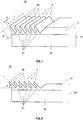
- Fig. 1 shows schematically a first component 10 with six lamellae 3.
- the component 10 comprises a metallic composite material 13, which consists of a first metallic material 11 and a second metallic material 12.
- the two materials 11 and 12 can have been bonded to one another by roll cladding.
- the second metallic material 12 has a greater electrical conductivity than the first metallic material 11 and it makes up the majority of the volume of the first component 10.
- a layer of the first metallic material 11 is only located on the surface of the first component 10.
- the lamellae 3 are machined from this first metallic material 11.
- the lamellae 3 are each connected to the first component 10 in a connection region 31 and extend from the surface of the first component 10 to the free end 32.
- the lamellae 3 are inclined with respect to the surface of the first component 10. The inclination of the slats 3 remains the same up to their free end 32.
- the lamellas have neither a kink nor a curvature. They thus extend linearly.
- the lamellas 3 each have the shape of a strip and have a length L, a width B and a thickness D.
- the width B is measured from the base of a lamella 3 at the connection area 31 to its free end 32.
- the lamellae 3 extend over the entire width of the component 10.
- the current-carrying capacity of the spring contact can be adjusted via the distance between adjacent lamellae 3. Regardless of the precise embodiment of the slats 3, the distance between adjacent slats can be 0.1 to 15 mm.
- the first component 10 also has an area in which there are no lamellae. Means (not shown) for contacting further electrical conductors can be present in this area, for example bores with screw connections.
- Fig. 2 shows a side view of a first component 10 according to FIG Fig. 1 .
- the angle ⁇ which the inclined lamellas 3 enclose with an imaginary line which is parallel to the surface of the first component 10 is approximately 45 °. No force acts on the slats 3. They are in their rest position.
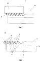
- Fig. 3 shows a side view of an arrangement 1 consisting of a first component 10 and a second component 20.
- the first component 10 corresponds to that in FIG Fig. 2
- the lamellae 3 of the first component 10 are in contact with the second component 20.
- the second component 20 exerts a force on the lamellae 3 in the direction of the first component 10.
- the slats 3 are deflected from their rest position. They lean more now than in the case of the Fig. 2 towards the surface of the first component 10 and the angle that they enclose with the surface of the first component 10 is smaller than in the rest position.
- the lamellae 3 exert a spring force on the second component 20.
- This spring force brings about a pressing force of the lamellae 3 against the surface of the second component 20.
- the higher the pressing force the lower the electrical contact resistance between the lamellae 3 and the second component 20. Because the lamellae 3 are an integral part of the first component 10, there is no significant electrical resistance between the first component 10 and the lamellae 3.
- Fig. 4 shows a side view of a first component 10 with lamellae 3, which have a kink.
- the lamellae 3 attach to the surface of the first component 10 at the same angle of inclination ⁇ as the lamellae 3 in the case of FIG Fig. 2 component 10 shown. At approximately half their width, the lamellae 3 have a kink.
- the contact area available for the transmission of the current is thus increased.
- Fig. 5 shows a side view of a first component 10 with convexly curved lamellae 3.
- the lamellae 3 attach to the surface of the first component 10 at the same angle of inclination as the lamellae 3 in the case of FIG Fig. 2 component 10 shown. Due to the convex curvature of the lamellae 3, the angle that the tangent to the surface of the lamella includes with the surface of the first component 10 changes continuously. It is getting smaller and smaller. At the free end 32 of the lamellas 3, this angle is approximately as large as the corresponding angle at the in Fig. 4 shown slats 3 with kink. Those related to Fig. 4 The effects and advantages described also apply to the in Fig. 5 illustrated embodiment.
- Fig. 6 shows schematically a first component 10 with segmented lamellae 3.
- the component 10 shown here can be used as a further development of the FIG Fig. 1 shown Component 10 can be seen.
- the lamellae 3 are each subdivided into several mutually adjacent segments 33 by cuts or slits.
- the cuts or slits can preferably extend into the connecting area 31 on the lamella base.
- the individual segments 33 can be deflected from their respective rest position independently of one another. As a result, the lamella 3 can better adapt to unevenness in the surface of the second component 20.
- the contact area is therefore larger.
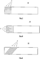
- first component 10 in the Figures 7, 8 and 9 a top view of a first component 10 is shown in each case.
- the respective first components 10 of these figures differ in the orientation of the lamellae 3 relative to the longitudinal extension of the first component 10, which in the Figures 7, 8 and 9 is designed as an example of a busbar.
- the in Fig. 7 The illustrated embodiment, the slats 3 are arranged transversely to the longitudinal extent of the busbar.
- the slats 3 are arranged parallel to the longitudinal extent of the busbar.
- the in Fig. 9 The illustrated embodiment, the slats 3 are arranged obliquely to the longitudinal extent of the busbar.
- the exemplary embodiments shown show the great flexibility of the arrangement according to the invention for transmitting electrical current from a first to a second component.
Landscapes
- Springs (AREA)
- Contacts (AREA)
- Manufacturing Of Electrical Connectors (AREA)
- Non-Insulated Conductors (AREA)
Abstract
Die Erfindung betrifft eine Anordnung (1) von Bauteilen (10, 20) zur Übertragung von elektrischem Strom von einem stromzuführenden Bauteil auf ein stromabführendes Bauteil, umfassend ein erstes Bauteil (10), welches das der Anordnung (1) stromzuführende Bauteil oder das von der Anordnung (1) stromabführende Bauteil ist, wobei das erste Bauteil (10) ein erstes metallisches Material (11) umfasst und auf mindestens einer Oberfläche mindestens eine aus dem ersten metallischen Material (11) an dieser Oberfläche herausgearbeitete federnde Lamelle (3) aus dem ersten metallischen Material (11) aufweist, wobei die mindestens eine Lamelle (3) so aus dem ersten metallischen Material (11) an der Oberfläche des ersten Bauteils (10) herausgearbeitet ist, dass sie in einem Verbindungsbereich (31) monolithisch mit dem ersten Bauteil (10) verbunden ist und sich ausgehend vom Verbindungsbereich (31) bis zu einem freien Ende (32) erstreckt, und dass sie bei Auslenkung aus ihrer Ruhelage in Richtung zur Oberfläche des ersten Bauteils (10) hin eine von der Oberfläche des Bauteils (10) weg gerichtete Federkraft ausübt, und ein zweites Bauteil (20), das in unmittelbarem Kontakt mit der mindestens einen Lamelle (3) des ersten Bauteils (10) steht.The invention relates to an arrangement (1) of components (10, 20) for the transmission of electrical current from a current-supplying component to a current-carrying component, comprising a first component (10) which is the component to be supplied with current to the arrangement (1) or that of the Arrangement (1) downstream component, wherein the first component (10) comprises a first metallic material (11) and on at least one surface at least one resilient lamella (3) worked out of the first metallic material (11) on this surface from the first metallic material (11), the at least one lamella (3) being worked out of the first metallic material (11) on the surface of the first component (10) in such a way that it is monolithically connected to the first component (31) in a connection area (31). 10) is connected and, starting from the connection area (31), extends to a free end (32), and that when it is deflected from its rest position in the direction of the O Surface of the first component (10) exerts a spring force directed away from the surface of the component (10), and a second component (20) which is in direct contact with the at least one lamella (3) of the first component (10).
Description
Die Erfindung betrifft ein System zur Übertragung von elektrischem Strom von einem ersten Bauteil auf ein zweites Bauteil, wobei das erste Bauteil in elektrischem Kontakt mit dem zweiten Bauteil steht. Solche Kontaktsysteme werden beispielsweise bei der Verschaltung von Batteriemodulen eingesetzt. Die Kontaktsysteme müssen dabei so gestaltet sein, dass sie Ströme mit einer Stromstärke von bis zu 500 A ohne großen Spannungsabfall übertragen können. Der gesamte Widerstand des Kontaktsystems muss also möglichst gering sein.The invention relates to a system for transmitting electrical current from a first component to a second component, the first component being in electrical contact with the second component. Such contact systems are used, for example, to interconnect battery modules. The contact systems must be designed in such a way that they can transmit currents with a current strength of up to 500 A without a large voltage drop. The total resistance of the contact system must therefore be as low as possible.
Die beiden Bauteile weisen üblicherweise einen Abstand auf, der durch ein Kontaktelement überbückt werden muss. Damit der Übergangswiderstand zwischen dem Kontaktelement und einem Bauteil möglichst klein ist, muss das Kontaktelement mit einer Mindestkraft an die Oberfläche des Bauteils gedrückt werden. Kontaktelemente weisen deshalb häufig einen Federmechanismus auf, der für die erforderliche Anpresskraft zwischen Kontaktelement und Bauteil sorgt. Die Anpresskraft muss über die gesamte Lebensdauer des Systems aufrecht erhalten werden, damit ein Anstieg des Kontaktwiderstands vermieden wird. Ferner muss das Kontaktelement Fertigungstoleranzen der Bauteile ausgleichen sowie Wärmeausdehnung und Vibrationen kompensieren können.The two components usually have a distance that has to be bridged by a contact element. So that the transition resistance between the contact element and a component is as small as possible, the contact element must be pressed against the surface of the component with a minimum force. Contact elements therefore often have a spring mechanism that provides the necessary contact pressure between the contact element and the component. The contact pressure must be maintained over the entire service life of the system in order to avoid an increase in contact resistance. Furthermore, the contact element must be able to compensate for manufacturing tolerances of the components and to compensate for thermal expansion and vibrations.
Grundsätzlich sollte die durch das Kontaktsystem bereitgestellte elektrische Verbindung zwischen den Bauteilen wieder lösbar sein, wenn man die Bauteile voneinander trennt. In einigen Fällen ist aber erwünscht, dass die elektrische Verbindung erhalten bleibt, wenn die Bauteile ihre Position zueinander verändern, insbesondere wenn sich der Abstand zwischen den Bauteilen durch unerwünschte äußere Einflüsse vergrößert. In diesen Fällen sollte die Verbindung zwischen den Bauteilen nahezu unlösbar, also nur mit erheblichem Aufwand wieder lösbar sein.Basically, the electrical provided by the contact system should Connection between the components can be released again when the components are separated from each other. In some cases, however, it is desirable that the electrical connection is maintained when the components change their position relative to one another, in particular when the distance between the components increases due to undesired external influences. In these cases, the connection between the components should be virtually indissoluble, that is, it should only be possible to detach it again with considerable effort.
Aus der Druckschrift
In der Druckschrift
Des Weiteren ist aus der
An derartigen Federelementen, die als zusätzliches Teil zwischen zwei Bauteilen eingebaut werden, ist nachteilhaft, dass der Strom zunächst vom einem ersten Bauteil auf das Federelement und dann vom Federelement auf ein zweites Bauteil übertragen werden muss. Das Kontaktsystem weist also mindestens zwei Kontaktstellen mit erheblichem Übergangswiderstand auf.The disadvantage of such spring elements, which are installed as an additional part between two components, is that the current must first be transmitted from a first component to the spring element and then from the spring element to a second component. The contact system thus has at least two contact points with considerable contact resistance.
Der Erfindung liegt die Aufgabe zugrunde, ein verbessertes System zur Kontaktierung von stromführenden Bauteilen, also zur Übertragung von elektrischem Strom von einem ersten auf ein zweites Bauteil, anzugeben. Insbesondere soll das System für Stromstärken zwischen 10 A und 500 A geeignet sein, einen geringen Übergangswiderstand aufweisen sowie einfach und kostengünstig herstellbar sein.The invention is based on the object of specifying an improved system for making contact with current-carrying components, that is to say for transmitting electrical current from a first to a second component. In particular, the system should be suitable for currents between 10 A and 500 A, have a low contact resistance and be simple and inexpensive to manufacture.
Die Erfindung wird durch die Merkmale des Anspruchs 1 wiedergegeben. Die weiteren rückbezogenen Ansprüche betreffen vorteilhafte Aus- und Weiterbildungen der Erfindung.The invention is represented by the features of
Die Erfindung schließt eine Anordnung von Bauteilen zur Übertragung von elektrischem Strom von einem stromzuführenden Bauteil auf ein stromabführendes Bauteil ein. Die Anordnung umfasst ein erstes Bauteil, welches das der Anordnung stromzuführende Bauteil oder das von der Anordnung stromabführende Bauteil ist. Das erste Bauteil umfasst ein erstes metallisches Material und weist auf mindestens einer Oberfläche mindestens eine aus dem ersten metallischen Material an dieser Oberfläche herausgearbeitete, insbesondere herausgeformte, federnde Lamelle aus dem ersten metallischen Material auf. Die mindestens eine Lamelle ist so aus dem ersten metallischen Material an der Oberfläche des ersten Bauteils herausgearbeitet, dass sie in einem Verbindungsbereich monolithisch mit dem ersten Bauteil verbunden ist und sich von diesem Verbindungsbereich ausgehend bis zu einem freien Ende erstreckt. Wird die Lamelle aus ihrer Ruhelage in Richtung senkrecht zur Oberfläche des ersten Bauteils hin ausgelenkt, übt sie eine von der Oberfläche des Bauteils weg gerichtete Federkraft aus. Diese Federkraft umfasst eine Komponente, die senkrecht zur Oberfläche des ersten Bauteils gerichtet ist, also eine Federnormalkraft. Ferner umfasst die Anordnung ein zweites Bauteil, das in unmittelbarem, also in direktem Kontakt mit der mindestens einen Lamelle des ersten Bauteils steht. Somit hat das erste Bauteil nicht nur die Funktion, die Anordnung mit weiteren, nicht zur Anordnung gehörenden Komponenten eines Stromkreises zu verbinden, sondern es dient gleichzeitig dazu, den elektrischen Kontakt zum zweiten Bauteil mittels mindestens einer federnden Lamelle herzustellen.The invention includes an arrangement of components for the transmission of electrical current from a current-supplying component to a current-carrying component. The arrangement comprises a first component, which is the component that supplies power to the arrangement or the component that carries current from the arrangement. The first component comprises a first metallic material and has, on at least one surface, at least one resilient lamella made of the first metallic material, in particular molded out, of the first metallic material on this surface. The at least one lamella is worked out of the first metallic material on the surface of the first component in such a way that it is monolithically connected to the first component in a connection area and extends from this connection area to a free end. If the lamella is deflected from its rest position in the direction perpendicular to the surface of the first component, it exerts a spring force directed away from the surface of the component. This spring force comprises a component which is directed perpendicular to the surface of the first component, that is to say a spring normal force. Furthermore, the arrangement comprises a second component that is in direct, that is, in direct contact with the at least one lamella of the first component. Thus, the first component not only has the function of connecting the arrangement with other components of a circuit that do not belong to the arrangement, but also serves to establish electrical contact with the second component by means of at least one resilient lamella.
Wird zur Beschreibung der Erfindung die mindestens eine Lamelle des ersten Bauteils hinsichtlich ihrer Position oder Ausrichtung in Relation zur Oberfläche des ersten Bauteils gesetzt, dann wird als Oberfläche des ersten Bauteils die äußere Fläche des ersten Bauteils verstanden, die resultieren würde, wenn die mindestens eine Lamelle entfernt werden würde.If, to describe the invention, the at least one lamella of the first component is set in relation to the surface of the first component in terms of its position or orientation, then the surface of the first component is understood to be the outer surface of the first component that would result if the at least one lamella would be removed.
Unter einer Lamelle kann ein band-, streifen- oder plattenförmiger Materialvorsprung der Dicke D, der Breite B und der Länge L verstanden werden. Die Länge L der Lamelle wird dabei entlang des Verbindungsbereichs gemessen, in dem sie monolithisch mit dem ersten Bauteil verbunden ist. Die Breite B der Lamelle wird vom Verbindungsbereich bis zum freien Ende der Lamelle gemessen. Die Dicke D wird senkrecht zur Oberfläche der Lamelle gemessen, also senkrecht zur Länge und zur Breite. Üblicherweise sind die Breite B und die Länge L jeweils größer als die Dicke D. Die Dicke D der Lamelle kann 0,05 bis 0,6 mm, bevorzugt 0,1 bis 0,3 mm betragen. Die Lamelle springt aus der Oberfläche des ersten Bauteils hervor, sie erhebt sich also über die Oberfläche des ersten Bauteils. Als Höhe der Lamelle kann der Abstand zwischen einem Punkt, an dem die Lamelle mit dem ersten Bauteil verbunden ist, und ihrem freien Ende definiert werden, wobei dieser Abstand senkrecht zur Oberfläche des ersten Bauteils gemessen wird. Die Höhe der Lamelle beträgt 0,1 bis 5 mm, bevorzugt 0,2 bis 2,5 mm.A lamella can be understood as a strip, strip or plate-shaped material projection of thickness D, width B and length L. The length L of the lamella is measured along the connection area in which it is monolithically connected to the first component. The width B of the lamella is measured from the connection area to the free end of the lamella. The thickness D is measured perpendicular to the surface of the lamella, i.e. perpendicular to the length and width. Usually, the width B and the length L are each greater than the thickness D. The thickness D of the lamella can be 0.05 to 0.6 mm, preferably 0.1 to 0.3 mm. The lamella protrudes from the surface of the first component, so it rises above the surface of the first component. The height of the lamella can be defined as the distance between a point at which the lamella is connected to the first component and its free end, this distance being measured perpendicular to the surface of the first component. The height of the lamella is 0.1 to 5 mm, preferably 0.2 to 2.5 mm.
Die Erfindung betrifft also ein System zur unmittelbaren Übertragung von elektrischem Strom von einem ersten Bauteil, welches das dem System stromzuführende Bauteil oder das vom System stromabführende Bauteil ist, auf ein zweites Bauteil durch mindestens ein federndes Kontaktelement, das in Form einer Lamelle aus der Oberfläche des ersten Bauteils herausgearbeitet ist. Das federnde Kontaktelement ist monolithisch mit dem ersten Bauteil verbunden. Es ist somit ein integraler Bestandteil des ersten Bauteils. Deshalb gibt es keinen elektrischen Übergangswiderstand zwischen dem ersten Bauteil und der Lamelle. Wird das erste Bauteil an der Oberfläche, die mindestens eine Lamelle aufweist, mit dem zweiten Bauteil in Kontakt gebracht, wird die federnde Lamelle aus ihrer Ruhelage in Richtung zum ersten Bauteil hin ausgelenkt. Als Reaktion übt sie eine Federnormalkraft auf das zweite Bauteil aus. Dadurch wird mittels der Lamelle ein kraftschlüssiger elektrischer Kontakt zwischen dem ersten Bauteil und dem zweiten Bauteil hergestellt. Die Größe der Federnormalkraft kann durch die Geometrie der Lamelle, ihren Neigungswinkel zur Oberfläche des ersten Bauteils und die Wahl ihres Materials eingestellt werden. Metallische Werkstoffe mit einem großen Elastizitätsmodul sind als Material der Lamelle besonders geeignet.The invention thus relates to a system for the direct transmission of electrical current from a first component, which the system The component that is to be supplied with current or the component that carries current away from the system is transferred to a second component by at least one resilient contact element which is machined from the surface of the first component in the form of a lamella. The resilient contact element is monolithically connected to the first component. It is therefore an integral part of the first component. Therefore there is no electrical contact resistance between the first component and the lamella. If the first component is brought into contact with the second component on the surface that has at least one lamella, the resilient lamella is deflected from its rest position in the direction of the first component. In response, it exerts a normal spring force on the second component. As a result, a non-positive electrical contact is established between the first component and the second component by means of the lamella. The size of the spring normal force can be adjusted by the geometry of the lamella, its angle of inclination to the surface of the first component and the choice of its material. Metallic materials with a large modulus of elasticity are particularly suitable as the material of the lamella.
Der besondere Vorteil dieser Anordnung von Bauteilen besteht darin, dass durch die Integration des lamellenförmigen, federnden Kontaktelements in das erste Bauteil ein Übergangswiderstand zwischen diesem Bauteil und dem Kontaktelement vermieden und somit der gesamte elektrische Widerstand der Anordnung deutlich reduziert wird. Ferner ist es nicht mehr erforderlich, zwischen dem ersten und dem zweiten Bauteil ein separates Kontaktelement einzufügen, beispielsweise ein Lamellenband. Die Anzahl der notwendigen Teile wird somit reduziert, wodurch Aufwand und Kosten verringert werden. Das erste Bauteil umfasst bereits das Kontaktelement zur Kontaktierung des zweiten Bauteils. Die gesamte Anordnung wird einfacher zu montieren und sicherer in ihrer Funktion, da ein separates Kontaktelement nicht mehr zwischen den stromführenden Bauteilen eingefügt werden muss und somit auch nicht versehentlich vergessen werden oder herausfallen kann. Darüber hinaus zeichnet sich die Anordnung durch eine kompakte Bauweise und einen geringen Platzbedarf aus. Vorteilhafterweise kann mindestens eines der beiden Bauteile im Bereich der Kontaktstelle zum anderen Bauteil eine metallische Beschichtung aufweisen, die beispielsweise Silber, Gold, Zinn und/oder Nickel umfassen kann. Durch eine solche Beschichtung wird der Übergangswiderstand zwischen den Bauteilen reduziert. Ebenso werden Reibkräfte und Verschleiß minimiert. Ferner verhindert die Beschichtung die Korrosion an der Oberfläche des Bauteils und sie kann als Diffusionsbarriere für das metallische Grundmaterial des Bauteils wirken.The particular advantage of this arrangement of components is that the integration of the lamellar, resilient contact element in the first component avoids transition resistance between this component and the contact element and thus significantly reduces the overall electrical resistance of the arrangement. Furthermore, it is no longer necessary to insert a separate contact element, for example a lamellar strip, between the first and the second component. The number of parts required is thus reduced, which reduces effort and costs. The first component already includes the contact element for making contact with the second component. The entire arrangement is easier to assemble and more reliable in its function, since a separate contact element no longer has to be inserted between the current-carrying components and thus cannot be accidentally forgotten or fall out. In addition, the arrangement is characterized by a compact design and a small footprint. At least one of the two components can advantageously have a metallic coating in the area of the contact point with the other component, which can include, for example, silver, gold, tin and / or nickel. Such a coating reduces the contact resistance between the components. Friction forces and wear are also minimized. Furthermore, the coating prevents corrosion on the surface of the component and it can act as a diffusion barrier for the metallic base material of the component.
Insbesondere kann das erste Bauteil eine Stromschiene sein. Eine Stromschiene ist ein starres, bevorzugt einstückiges Bauteil aus einem elektrisch leitenden Material, insbesondere aus Metall, welches der Übertragung und Verteilung von elektrischen Strömen dient. Eine Stromschiene kann beispielsweise ein gerades Flachprofil sein, sie kann aber auch ein gebogenes oder abgewinkeltes Flachprofil sein. Das Profil der Stromschiene kann aber auch andere Formen, beispielsweise U-Form oder L-Form aufweisen oder es kann rund sein. Eine Stromschiene hat mindestens zwei Kontaktbereiche, nämlich mindestens einen für die Stromzuführung und mindestens einen für die Stromabführung. Wird eine Stromschiene in der erfindungsgemäßen Anordnung als erstes Bauteil verwendet, dann weist sie in mindestens einem ihrer Kontaktbereiche mindestens eine federnde Lamelle wie vorstehend beschrieben auf. Mittels dieser Lamelle wird ein Kontakt zu einem zweiten Bauteil hergestellt, das ebenfalls eine Stromschiene sein kann. Der andere Kontaktbereich der Stromschiene kann beliebige Mittel zur Kontaktierung einer weiteren, nicht zur Anordnung gehörenden elektrischen Komponente aufweisen, beispielsweise Klemmvorrichtungen, Aussparungen oder Bohrungen, die optional ein Innengewinde aufweisen können. Besonders bevorzugt kann die Stromschiene mehrere Kontaktbereiche aufweisen, die jeweils mindestens eine federnde Lamelle aufweisen. Eine solche Stromschiene kann zur Verteilung von Strömen verwendet werden, beispielsweise in einem Stromspeicher zur Verteilung von Teilströmen auf einzelne Speichermodule.In particular, the first component can be a busbar. A busbar is a rigid, preferably one-piece component made of an electrically conductive material, in particular made of metal, which is used to transmit and distribute electrical currents. A busbar can, for example, be a straight flat profile, but it can also be a curved or angled flat profile. The profile of the busbar can, however, also have other shapes, for example U-shape or L-shape, or it can be round. A busbar has at least two contact areas, namely at least one for the power supply and at least one for the power take-off. If a busbar is used as the first component in the arrangement according to the invention, then it has at least one resilient lamella in at least one of its contact areas, as described above. By means of this lamella, contact is made with a second component, which can also be a busbar. The other contact area of the busbar can have any means for contacting a further electrical component not belonging to the arrangement, for example clamping devices, recesses or bores, which can optionally have an internal thread. The busbar can particularly preferably have a plurality of contact areas, each of which has at least one resilient lamella. Such a busbar can be used to distribute currents, for example in a power storage unit for distributing partial currents to individual storage modules.
In bevorzugter Ausgestaltung der Erfindung können sich im Strompfad der Anordnung lediglich das erste Bauteil und das zweite Bauteil befinden. Die Anordnung umfasst im Strompfad also keine weiteren Bauteile: Das erste Bauteil ist das der Anordnung stromzuführende Bauteil oder das von der Anordnung stromabführende Bauteil, während das zweite Bauteil das bezüglich Stromfluss zum ersten Bauteil komplementäre stromabführende oder stromzuführende Bauteil ist. Hinsichtlich der stromführenden Komponenten besteht die Anordnung also nur aus dem ersten und dem zweiten Bauteil. Mit anderen Worten, bei dieser Ausgestaltung besteht der Strompfad innerhalb der Anordnung nur aus dem ersten Bauteil und dem zweiten Bauteil. Durch eine derartige Anordnung wird ein System zur Kontaktierung von zwei stromführenden Bauteilen bereitgestellt, das im Strompfad lediglich eine mechanische Kontaktstelle aufweist.In a preferred embodiment of the invention, only the first component and the second component can be located in the current path of the arrangement. The arrangement therefore does not include any further components in the current path: the first component is the component that feeds current to the arrangement or the component that carries current from the arrangement, while the second component is the component that carries current or that is complementary to the first component in terms of current flow. With regard to the current-carrying components, the arrangement therefore only consists of the first and the second component. In other words, in this refinement, the current path within the arrangement consists only of the first component and the second component. Such an arrangement provides a system for contacting two current-carrying components which only has one mechanical contact point in the current path.
Im Rahmen dieser bevorzugten Ausgestaltung der Erfindung ist jedoch nicht ausgeschlossen, dass die gesamte Anordnung weitere Komponenten außerhalb des Strompfads umfasst, beispielsweise Vorrichtungen zur Positionierung und Montage des ersten und des zweiten Bauteils. Ebenso kann das erste oder das zweite Bauteil außerhalb der Anordnung mit anderen elektrischen oder elektronischen Komponenten, beispielsweise einem Widerstand, einem Schalter, einem Relais oder einem Schütz, in Verbindung stehen.In the context of this preferred embodiment of the invention, however, it is not excluded that the entire arrangement comprises further components outside the current path, for example devices for positioning and assembling the first and the second component. Likewise, the first or the second component outside the arrangement can be connected to other electrical or electronic components, for example a resistor, a switch, a relay or a contactor.
Vorteilhafterweise kann die mindestens eine Lamelle mittels eines Trennprozesses, insbesondere eines Schneid-, Meißel-, Schäl-, Pflüg- oder Furchprozesses, und mittels eines Biegeprozesses aus dem ersten metallischen Material des ersten Bauteils herausgearbeitet sein. Die Lamelle wird aus einer Materialschicht gebildet, die durch einen geeigneten Trennprozess von der ursprünglichen Oberfläche des ersten Bauteils derart herausgearbeitet wurde, dass die Materialschicht nicht vollständig von der Oberfläche abgetrennt wird, sondern in einem Verbindungsbereich mit dem ersten Bauteil monolithisch verbunden bleibt. Diese Materialschicht wird durch einen Biegeprozess von der Oberfläche des ersten Bauteils angehoben, indem die Materialschicht um eine gedachte Achse, die sich entlang des Verbindungsbereichs erstreckt, gebogen wird. Trenn- und Biegeprozess können auch in einem Arbeitsschritt durchgeführt werden. Die Lamelle ist also aus dem Material an der Oberfläche des ersten Bauteils herausgeformt und bildet einen Materialvorsprung. Der Vorteil dieser Ausführungsform besteht darin, dass eine hohe Materialausnutzung erreicht wird, denn es entsteht beispielsweise kein Stanzabfall bei der Herstellung der federnden Lamellen.The at least one lamella can advantageously be worked out of the first metallic material of the first component by means of a cutting process, in particular a cutting, chiselling, peeling, plowing or furrowing process, and by means of a bending process. The lamella is formed from a material layer that has been worked out from the original surface of the first component by a suitable separation process in such a way that the material layer is not completely separated from the surface, but monolithically in a connection area with the first component remains connected. This material layer is lifted from the surface of the first component by a bending process in that the material layer is bent about an imaginary axis that extends along the connection area. Cutting and bending processes can also be carried out in one work step. The lamella is thus formed out of the material on the surface of the first component and forms a material projection. The advantage of this embodiment is that a high level of material utilization is achieved because, for example, there is no punching waste in the manufacture of the resilient lamellae.
Im Rahmen dieser vorteilhaften Ausführungsform kann die vorstehend beschriebene, metallische Beschichtung des Bauteils im Bereich der Kontaktfläche auf der Oberfläche des ersten Bauteils aufgebracht werden, bevor die mindestens eine Lamelle aus dem Material des ersten Bauteils herausgearbeitet wird.In the context of this advantageous embodiment, the above-described metallic coating of the component can be applied in the area of the contact area on the surface of the first component before the at least one lamella is machined from the material of the first component.
Ferner kann im Rahmen in einer speziellen Ausgestaltung dieser vorteilhaften Ausführungsform der Erfindung das erste metallische Material des ersten Bauteils im Verbindungsbereich eine größere Härte aufweisen als außerhalb des Verbindungsbereichs. Der Verbindungsbereich kann auch als Basis der Lamelle bezeichnet werden. Durch den Trenn- und Biegeprozess bei der Herausarbeitung der Lamelle wurde das Material dort plastisch umgeformt. Dies führt zu einer lokalen Aufhärtung des Werkstoffs im Verbindungsbereich. Deshalb weist das Material lokal eine höhere Festigkeit und eine höhere Härte auf. Die höhere Festigkeit hat den Vorteil, dass die Lamelle eine größere Federkraft ausüben kann ohne plastisch verformt zu werden. Die Federwirkung wird dadurch verbessert und der Übergangswiderstand im Kontaktbereich verringert.Furthermore, in a special configuration of this advantageous embodiment of the invention, the first metallic material of the first component can have a greater hardness in the connection area than outside the connection area. The connection area can also be referred to as the base of the lamella. The material was plastically deformed there by the cutting and bending process when working out the lamella. This leads to a local hardening of the material in the connection area. Therefore, the material has a higher strength and a higher hardness locally. The higher strength has the advantage that the lamella can exert a greater spring force without being plastically deformed. This improves the spring effect and reduces the contact resistance in the contact area.
Bei einer weiteren vorteilhaften Ausführungsform der Erfindung kann sich die mindestens eine Lamelle in Ruhelage unter einem Winkel α kleiner 80° zur Oberfläche des ersten Bauteils geneigt erstrecken. Der Neigungswinkel α wird im Ansatzpunkt der Lamelle an die Oberfläche des ersten Bauteils, also im Verbindungsbereich gemessen. Durch die zur Oberfläche des Bauteils geneigte Anordnung der Lamelle kann die Federwirkung der Lamelle gut realisiert werden.In a further advantageous embodiment of the invention, the at least one lamella can be in the rest position at an angle α less than 80 ° to Surface of the first component extend inclined. The angle of inclination α is measured at the point where the lamella attaches to the surface of the first component, i.e. in the connection area. Due to the arrangement of the lamella inclined to the surface of the component, the spring effect of the lamella can be implemented well.
Im Rahmen einer speziellen Ausgestaltung dieser Ausführungsform kann der Winkel a, unter dem sich die Lamelle in Ruhelage zur Oberfläche des ersten Bauteils erstreckt, 40° bis 70° betragen. Wenn der Winkel α kleiner als 40° ist, dann ist die maximale Auslenkung der Lamelle aus ihrer Ruhelage zu gering um eine ausreichend große Federkraft zu erzeugen. Ist der Winkel α größer 70°, dann ist die Komponente der Federkraft senkrecht zur Oberfläche des ersten Bauteils relativ klein, so dass bei kleinen Auslenkungen der Lamelle nur eine kleine Federnormalkraft wirkt.In the context of a special configuration of this embodiment, the angle a at which the lamella extends in the rest position to the surface of the first component can be 40 ° to 70 °. If the angle α is less than 40 °, then the maximum deflection of the lamella from its rest position is too small to generate a sufficiently large spring force. If the angle α is greater than 70 °, the component of the spring force perpendicular to the surface of the first component is relatively small, so that only a small normal spring force acts with small deflections of the lamella.
Bei einer besonders vorteilhaften Ausführungsform der Erfindung kann die mindestens eine Lamelle auf ihrer von der Oberfläche des ersten Bauteils abgewandten Seite zwischen dem Verbindungsbereich und dem freien Ende der Lamelle eine konvexe Kontur aufweisen. Insbesondere kann die Lamelle eine konvexe Krümmung oder einen Knick aufweisen, der eine konvexe Außenkontur der Lamelle zur Folge hat. Bei einer konvexen Krümmung der Lamelle verändert sich der Winkel, den die Tangente an die Lamelle mit der Oberfläche des ersten Bauteils einschließt, in der Weise, dass dieser Winkel mit zunehmender Entfernung von der Lamellenbasis kleiner wird. Bei einem konvexen Knick ist der Tangentenwinkel im Bereich zwischen Knick und freiem Ende der Lamelle kleiner als im Bereich zwischen Lamellenbasis und Knick. Durch die konvexe Kontur der Lamelle wird die Fläche, mit der die Lamelle mit dem zweiten Bauteil in Kontakt stehen kann, vergrößert. Der Vorteil diese Ausführungsform ist folglich eine hohe Federkraft der Lamelle bei gleichzeitig großer Kontaktfläche mit dem zweiten Bauteil.In a particularly advantageous embodiment of the invention, the at least one lamella can have a convex contour on its side facing away from the surface of the first component between the connection area and the free end of the lamella. In particular, the lamella can have a convex curvature or a kink, which results in a convex outer contour of the lamella. In the case of a convex curvature of the lamella, the angle which the tangent to the lamella includes with the surface of the first component changes in such a way that this angle becomes smaller with increasing distance from the lamella base. In the case of a convex kink, the tangent angle in the area between the kink and the free end of the lamella is smaller than in the area between the lamella base and the kink. Due to the convex contour of the lamella, the area with which the lamella can be in contact with the second component is enlarged. The advantage of this embodiment is consequently a high spring force of the lamella with, at the same time, a large contact area with the second component.
In einer weiteren bevorzugten Ausführungsform kann die mindestens eine Lamelle von ihrem freien Ende ausgehend in mehrere Segmente geteilt, insbesondere quergeteilt sein. Die so gebildeten Segmente sind in Längsrichtung der Lamelle benachbart angeordnet. Die einzelnen Segmente können bei Kontakt mit der Oberfläche des zweiten Bauteils unterschiedlich weit aus ihrer jeweiligen Ruhelage ausgelenkt werden. Durch das Teilen der Lamelle in benachbarte Segmente können folglich Unebenheiten in der Oberfläche des zweiten Bauteils besser ausgeglichen werden als bei einer ungeteilten Lamelle.In a further preferred embodiment, the at least one lamella can, starting from its free end, be divided into several segments, in particular divided transversely. The segments formed in this way are arranged adjacent to the lamella in the longitudinal direction. When in contact with the surface of the second component, the individual segments can be deflected to different extents from their respective rest position. By dividing the lamella into adjacent segments, unevenness in the surface of the second component can consequently be better compensated than with an undivided lamella.
Vorteilhafterweise kann das erste Bauteil zumindest teilweise aus einem metallischen Verbundmaterial bestehen, welches das erste metallische Material sowie ein zweites metallisches Material umfasst, wobei das zweite metallische Material eine höhere elektrische Leitfähigkeit als das erste metallische Material aufweist. Bei einem derartigen Verbundmaterial werden die beiden Funktionen des ersten Bauteils, nämlich Stromtransport einerseits und Bereitstellung eines federnden Kontaktelements andererseits, durch die Verwendung unterschiedlicher Materialien unterstützt. Das erste metallische Material, das die äußere Lage des ersten Bauteils bildet, weist gute Festigkeits- und Federeigenschaften auf und ist somit für die Funktion der federnden Lamelle optimiert. Der überwiegende Volumenanteil des ersten Bauteils besteht aus dem zweiten metallischen Material. Dieses trägt aufgrund seiner hohen elektrischen Leitfähigkeit zu einem geringen elektrischen Widerstand der Anordnung bei. Da aus diesem zweiten Material keine federnde Lamelle geformt wird, ist es akzeptabel, wenn seine Festigkeits- und Federeigenschaften schlechter sind als die des ersten metallischen Materials. Das erste metallische Material kann insbesondere eine spezielle Kupferlegierung sein, während das zweite metallische Material insbesondere hochreines Kupfer oder Aluminium sein kann.The first component can advantageously consist at least partially of a metallic composite material which comprises the first metallic material and a second metallic material, the second metallic material having a higher electrical conductivity than the first metallic material. With such a composite material, the two functions of the first component, namely current transport on the one hand and provision of a resilient contact element on the other hand, are supported by the use of different materials. The first metallic material, which forms the outer layer of the first component, has good strength and spring properties and is therefore optimized for the function of the resilient lamella. The majority of the volume of the first component consists of the second metallic material. Due to its high electrical conductivity, this contributes to a low electrical resistance of the arrangement. Since no resilient lamella is formed from this second material, it is acceptable if its strength and resilience properties are inferior to those of the first metallic material. The first metallic material can in particular be a special copper alloy, while the second metallic material can in particular be high-purity copper or aluminum.
Ferner zeichnet sich das metallische Verbundmaterial dadurch aus, dass das erste und das zweite Material so miteinander verbunden sind, dass bei Stromfluss über die Grenzfläche zwischen diesen beiden Materialien kein nennenswerter elektrischer Widerstand an der Grenzfläche ist. Insbesondere können das erste und das zweite metallische Material stoffschlüssig miteinander verbunden sein. Dies kann beispielsweise durch einen Plattierprozess erfolgen. Ferner kann zur Reduzierung des Übergangswiderstands zwischen dem ersten und dem zweiten metallischen Material eine Beschichtung, die beispielsweise Silber, Gold, Zinn und/oder Nickel umfasst, vorgesehen sein.Furthermore, the metallic composite material is characterized in that the first and the second material are connected to one another in such a way that when a current flows there is no significant electrical resistance at the interface across the interface between these two materials. In particular, the first and the second metallic material can be materially connected to one another. This can be done, for example, by a plating process. Furthermore, in order to reduce the contact resistance between the first and the second metallic material, a coating which comprises, for example, silver, gold, tin and / or nickel, can be provided.
In vorteilhafter Ausgestaltung der Erfindung kann das erste Bauteil eine elektrisch isolierende Schicht aufweisen, die auf der von der Oberfläche des ersten Bauteils abgewandten Seite der Lamelle zumindest teilweise entfernt ist. Durch eine derartige isolierende Schicht ist das erste Bauteil in einem großen Teil seiner Oberfläche elektrisch isoliert und es liegen nur die Stellen der Oberfläche des ersten Bauteils frei, die in Kontakt zu dem zweiten Bauteil stehen. Die Sicherheit der gesamten Anordnung wird dadurch verbessert. Zur Herstellung einer solchen Ausgestaltung kann beispielsweise ein vorisoliertes Profil oder eine vorisolierte Stromschiene verwendet werden.In an advantageous embodiment of the invention, the first component can have an electrically insulating layer which is at least partially removed on the side of the lamella facing away from the surface of the first component. The first component is electrically insulated over a large part of its surface by such an insulating layer and only those areas of the surface of the first component which are in contact with the second component are exposed. This improves the safety of the entire arrangement. For example, a pre-insulated profile or a pre-insulated busbar can be used to produce such a configuration.
In einer bevorzugten Ausführungsform der Erfindung kann das zweite Bauteil zumindest teilweise aus einem metallischen Material bestehen und auf mindestens einer Oberfläche mindestens eine federnde Lamelle aus dem metallischen Material aufweisen. Die Lamelle ist dabei so aus dem metallischen Material an der Oberfläche des zweiten Bauteils herausgearbeitet, dass sie in einem Verbindungsbereich monolithisch mit dem zweiten Bauteil verbunden ist und sich ausgehend vom Verbindungsbereich bis zu einem freien Ende erstreckt. Die mindestens eine Lamelle des zweiten Bauteils steht mit der mindestens einen Lamelle des ersten Bauteils in Kontakt. Bei dieser Ausführungsform weisen also sowohl das erste Bauteil als auch das zweite Bauteil jeweils mindestens eine federnde Lamelle zur Kontaktierung des anderen Bauteils auf. Einander gegenüber liegende Lamellen der beiden Bauteile können in elektrischem Kontakt stehen. Auf dieser Weise wird ein größerer Federweg gebildet als wenn nur eines der Bauteile federnde Lamellen aufweist. Auf diese Weise können auch große Abstände zwischen dem ersten und dem zweiten Bauteil sicher überbrückt werden. Hinsichtlich der Gestaltung der mindestens einen federnden Lamelle des zweiten Bauteils wird explizit auf die Ausführungsformen der mindestens einen federnden Lamelle des ersten Bauteils verwiesen.In a preferred embodiment of the invention, the second component can at least partially consist of a metallic material and have at least one resilient lamella made of the metallic material on at least one surface. The lamella is worked out of the metallic material on the surface of the second component in such a way that it is monolithically connected to the second component in a connection area and extends from the connection area to a free end. The at least one lamella of the second component is in contact with the at least one lamella of the first component. In this embodiment, both the first component and the second component each have at least one resilient lamella for contacting the other component. Opposite lamellae of the two components can be in electrical contact stand. In this way, a greater spring travel is formed than if only one of the components has resilient lamellae. In this way, even large distances between the first and the second component can be safely bridged. With regard to the design of the at least one resilient lamella of the second component, explicit reference is made to the embodiments of the at least one resilient lamella of the first component.
Im Rahmen einer speziellen Ausgestaltung dieser bevorzugten Ausführungsform kann die mindestens eine Lamelle des ersten Bauteils so mit der mindestens einen Lamelle des zweiten Bauteils in Kontakt stehen, dass das erste Bauteil mit dem zweiten Bauteil verbunden bleibt, wenn die Bauteile ihre Position zueinander verändern, insbesondere, wenn sich der Abstand zwischen den Bauteilen vergrößert. Die Lamellen sind hierbei so eingerichtet, dass das erste Bauteil quasi unlösbar oder nahezu unlösbar, also nur mit erheblichem Aufwand lösbar, mit dem zweiten Bauteil verbunden ist. Die Lamellen der beiden Bauteile können beispielsweise gegenseitig einrasten oder sich ineinander verhaken. Der Vorteil dieser speziellen Ausgestaltung ist, dass der elektrische Kontakt zwischen dem ersten und dem zweiten Bauteil besonders sicher erhalten bleibt. Durch äußere Einflüsse, wie zum Beispiel Erschütterungen oder thermische Ausdehnung, kann sich der Abstand zwischen dem ersten und dem zweiten Bauteil ungewollt vergrößern. Bei dieser speziellen Ausgestaltung der Erfindung bleibt auch in diesen Fällen der elektrische Kontakt zwischen den beiden Bauteilen bestehen.In the context of a special configuration of this preferred embodiment, the at least one lamella of the first component can be in contact with the at least one lamella of the second component in such a way that the first component remains connected to the second component when the components change their position relative to one another, in particular, when the distance between the components increases. The lamellae are set up in such a way that the first component is connected to the second component in a manner that is virtually non-detachable or almost non-detachable, that is to say can only be detached with considerable effort. The lamellas of the two components can, for example, snap into one another or hook into one another. The advantage of this special configuration is that the electrical contact between the first and the second component is maintained in a particularly reliable manner. External influences, such as vibrations or thermal expansion, can inadvertently increase the distance between the first and the second component. With this special embodiment of the invention, the electrical contact between the two components remains in place even in these cases.
Hinsichtlich weiterer technischer Merkmale und Vorteile der erfindungsgemäßen Anordnung wird hiermit explizit auf die Figuren, die Figurenbeschreibung und die Ausführungsbeispiele verwiesen.With regard to further technical features and advantages of the arrangement according to the invention, explicit reference is hereby made to the figures, the description of the figures and the exemplary embodiments.
Ausführungsbeispiele der Erfindung werden anhand der schematischen Zeichnungen näher erläutert. Darin zeigen:
- Fig. 1
- schematisch ein erstes Bauteil mit linearen Lamellen
- Fig. 2
- eine Seitenansicht eines ersten Bauteils mit linearen Lamellen
- Fig. 3
- eine Anordnung eines ersten Bauteils und eines zweiten Bauteils
- Fig. 4
- eine Seitenansicht eines ersten Bauteils mit Lamellen mit Knick
- Fig. 5
- eine Seitenansicht eines ersten Bauteils mit konvex gekrümmten Lamellen
- Fig. 6
- schematisch ein erstes Bauteil mit segmentierten Lamellen
- Fig. 7
- eine Draufsicht eines erstes Bauteil mit quer verlaufenden Lamellen
- Fig. 8
- eine Draufsicht eines ersten Bauteils mit längs verlaufenden Lamellen
- Fig. 9
- eine Draufsicht eines ersten Bauteils mit schräg verlaufenden Lamellen
- Fig. 1
- schematically a first component with linear lamellae
- Fig. 2
- a side view of a first component with linear lamellae
- Fig. 3
- an arrangement of a first component and a second component
- Fig. 4
- a side view of a first component with lamellae with a kink
- Fig. 5
- a side view of a first component with convex curved lamellae
- Fig. 6
- schematically a first component with segmented lamellae
- Fig. 7
- a plan view of a first component with transverse lamellae
- Fig. 8
- a plan view of a first component with longitudinally extending lamellae
- Fig. 9
- a top view of a first component with obliquely extending lamellae
Einander entsprechende Teile sind in allen Figuren mit denselben Bezugszeichen versehen.Corresponding parts are provided with the same reference symbols in all figures.
Die Lamellen 3 haben jeweils die Form eines Streifens und weisen eine Länge L, eine Breite B und eine Dicke D auf. Die Breite B wird von der Basis einer Lamelle 3 am Verbindungsbereich 31 bis zu deren freiem Ende 32 gemessen. Die Lamellen 3 erstrecken sich über die gesamte Breite des Bauteils 10. Über den Abstand benachbarter Lamellen 3 kann die Stromtragfähigkeit des Federkontakts eingestellt werden. Unabhängig von der genauen Ausführungsform der Lamellen 3 kann der Abstand benachbarter Lamellen 0,1 bis 15 mm betragen.The
Das erste Bauteil 10 weist ferner einen Bereich auf, in dem keine Lamellen vorhanden sind. In diesem Bereich können (nicht dargestellte) Mittel zur Kontaktierung weiterer elektrischer Leiter vorhanden sein, beispielsweise Bohrungen mit Verschraubungen.The
In den
- 11
- Anordnungarrangement
- 1010
- erstes Bauteilfirst component
- 1111
- erstes metallisches Materialfirst metallic material
- 1212th
- zweites metallisches Materialsecond metallic material
- 1313th
- VerbundmaterialComposite material
- 2020th
- zweites Bauteilsecond component
- 33
- LamelleLamella
- 3131
- VerbindungsbereichConnection area
- 3232
- freies Endefree end
- 3333
- Segmentsegment
- BB.
- Breite der LamelleWidth of the lamella
- DD.
- Dicke der LamelleThickness of the lamella
- LL.
- Länge der LamelleLength of the lamella
- αα
- Winkelangle
Claims (12)
ein erstes Bauteil (10), welches das der Anordnung (1) stromzuführende Bauteil oder das von der Anordnung (1) stromabführende Bauteil ist, wobei das erste Bauteil (10) ein erstes metallisches Material (11) umfasst und auf mindestens einer Oberfläche mindestens eine aus dem ersten metallischen Material (11) an dieser Oberfläche herausgearbeitete federnde Lamelle (3) aus dem ersten metallischen Material (11) aufweist, wobei die mindestens eine Lamelle (3) so aus dem ersten metallischen Material (11) an der Oberfläche des ersten Bauteils (10) herausgearbeitet ist, dass sie in einem Verbindungsbereich (31) monolithisch mit dem ersten Bauteil (10) verbunden ist und sich ausgehend vom Verbindungsbereich (31) bis zu einem freien Ende (32) erstreckt, und dass sie bei Auslenkung aus ihrer Ruhelage in Richtung zur Oberfläche des ersten Bauteils (10) hin eine von der Oberfläche des Bauteils (10) weg gerichtete Federkraft ausübt,
und ein zweites Bauteil (20), das in unmittelbarem Kontakt mit der mindestens einen Lamelle (3) des ersten Bauteils (10) steht.An arrangement (1) of components (10, 20) for the transmission of electrical current from a current-supplying component to a current-carrying component, comprising
a first component (10), which is the component supplying current to the arrangement (1) or the component carrying current downstream from the arrangement (1), the first component (10) comprising a first metallic material (11) and at least one on at least one surface from the first metallic material (11) worked out resilient lamella (3) made of the first metallic material (11), the at least one lamella (3) being made of the first metallic material (11) on the surface of the first component (10) is worked out that it is monolithically connected to the first component (10) in a connection area (31) and extends from the connection area (31) to a free end (32), and that when deflected from its rest position in the direction of the surface of the first component (10) exerts a spring force directed away from the surface of the component (10),
and a second component (20) which is in direct contact with the at least one lamella (3) of the first component (10).
Applications Claiming Priority (1)
| Application Number | Priority Date | Filing Date | Title |
|---|---|---|---|
| DE102020001379.1A DE102020001379B3 (en) | 2020-03-03 | 2020-03-03 | Arrangement of components for the transmission of electrical current |
Publications (2)
| Publication Number | Publication Date |
|---|---|
| EP3876356A1 true EP3876356A1 (en) | 2021-09-08 |
| EP3876356B1 EP3876356B1 (en) | 2024-02-28 |
Family
ID=74625781
Family Applications (1)
| Application Number | Title | Priority Date | Filing Date |
|---|---|---|---|
| EP21000044.4A Active EP3876356B1 (en) | 2020-03-03 | 2021-02-11 | Arrangement of components for electrical power transmission |
Country Status (6)
| Country | Link |
|---|---|
| US (1) | US11349245B2 (en) |
| EP (1) | EP3876356B1 (en) |
| JP (1) | JP2021141056A (en) |
| KR (1) | KR20210112239A (en) |
| CN (1) | CN113363769A (en) |
| DE (1) | DE102020001379B3 (en) |
Families Citing this family (1)
| Publication number | Priority date | Publication date | Assignee | Title |
|---|---|---|---|---|
| KR20230082482A (en) | 2021-12-01 | 2023-06-08 | 한국단자공업 주식회사 | Contact spring and terminal assembly having the same |
Citations (8)
| Publication number | Priority date | Publication date | Assignee | Title |
|---|---|---|---|---|
| DE148159C (en) | 1899-08-13 | 1904-02-09 | ||
| DE3412849A1 (en) | 1983-04-07 | 1984-10-11 | Siemens AG, 1000 Berlin und 8000 München | Electrical contacting device |
| EP0202564A2 (en) | 1985-05-20 | 1986-11-26 | Multi-Contact AG Basel | Electrical contacting device |
| JPH0569866U (en) * | 1992-02-26 | 1993-09-21 | 古河電気工業株式会社 | Connecting terminal |
| EP0856913A1 (en) * | 1997-02-03 | 1998-08-05 | Grote & Hartmann GmbH & Co. KG | High current contact element |
| DE102007030134B3 (en) * | 2007-06-29 | 2008-10-02 | Rahnenführer, Dirk | Conductor pin and socket connector for electrically connecting two electrical conductors, has V-shaped or circular arc-shaped conductor rail arranged on housing and inserted into ring, where rail is electrically connected with grooves |
| DE102013015088A1 (en) * | 2013-09-14 | 2015-03-19 | G. Rau Gmbh & Co. Kg | Electrical contact element for a mechanically switchable electrical switch contact and method for its production |
| WO2016187089A1 (en) * | 2015-05-20 | 2016-11-24 | Delphi Technologies, Inc. | An electroconductive material with an undulating surface, an electrical terminal formed of said material, and a method of producing said material |
Family Cites Families (12)
| Publication number | Priority date | Publication date | Assignee | Title |
|---|---|---|---|---|
| FR844859A (en) | 1937-10-18 | 1939-08-03 | Plug-in coupling device for socket-outlet, with multiple spring-loaded contacts arranged in a circle in one or more planes | |
| DE1068780B (en) | 1957-10-14 | 1959-11-12 | ||
| US2946039A (en) * | 1957-11-06 | 1960-07-19 | Durakool Inc | Electrical terminal |
| US3678445A (en) * | 1970-07-31 | 1972-07-18 | Itt | Electrical connector shield |
| DE2243034C2 (en) | 1972-09-01 | 1974-09-19 | Multi-Contact Ag, Basel (Schweiz) | Electrical contact arrangement |
| CH590569A5 (en) | 1975-10-27 | 1977-08-15 | Sprecher & Schuh Ag | |
| JPS569866U (en) | 1979-07-03 | 1981-01-28 | ||
| US9401570B2 (en) * | 2014-10-29 | 2016-07-26 | Tyco Electronics Corporation | Electrical connector having ground bus bar |
| US10103468B2 (en) * | 2015-03-06 | 2018-10-16 | Kd&E Solar, Llc. | Coating displacement electrical connecting device and related methods |
| DE102018119844B4 (en) | 2018-07-26 | 2022-10-06 | Auto-Kabel Management Gmbh | Electrical connection and method of making an electrical connection |
| DE102018216965B3 (en) | 2018-10-02 | 2020-01-16 | Leoni Bordnetz-Systeme Gmbh | Method for contacting two electrical lines and plug device |
| TW202109981A (en) * | 2019-01-14 | 2021-03-01 | 美商安姆芬諾爾公司 | Small form factor interposer |
-
2020
- 2020-03-03 DE DE102020001379.1A patent/DE102020001379B3/en active Active
-
2021
- 2021-01-20 KR KR1020210008152A patent/KR20210112239A/en unknown
- 2021-01-25 CN CN202110114437.8A patent/CN113363769A/en active Pending
- 2021-01-27 JP JP2021010876A patent/JP2021141056A/en active Pending
- 2021-02-11 EP EP21000044.4A patent/EP3876356B1/en active Active
- 2021-02-19 US US17/179,714 patent/US11349245B2/en active Active
Patent Citations (8)
| Publication number | Priority date | Publication date | Assignee | Title |
|---|---|---|---|---|
| DE148159C (en) | 1899-08-13 | 1904-02-09 | ||
| DE3412849A1 (en) | 1983-04-07 | 1984-10-11 | Siemens AG, 1000 Berlin und 8000 München | Electrical contacting device |
| EP0202564A2 (en) | 1985-05-20 | 1986-11-26 | Multi-Contact AG Basel | Electrical contacting device |
| JPH0569866U (en) * | 1992-02-26 | 1993-09-21 | 古河電気工業株式会社 | Connecting terminal |
| EP0856913A1 (en) * | 1997-02-03 | 1998-08-05 | Grote & Hartmann GmbH & Co. KG | High current contact element |
| DE102007030134B3 (en) * | 2007-06-29 | 2008-10-02 | Rahnenführer, Dirk | Conductor pin and socket connector for electrically connecting two electrical conductors, has V-shaped or circular arc-shaped conductor rail arranged on housing and inserted into ring, where rail is electrically connected with grooves |
| DE102013015088A1 (en) * | 2013-09-14 | 2015-03-19 | G. Rau Gmbh & Co. Kg | Electrical contact element for a mechanically switchable electrical switch contact and method for its production |
| WO2016187089A1 (en) * | 2015-05-20 | 2016-11-24 | Delphi Technologies, Inc. | An electroconductive material with an undulating surface, an electrical terminal formed of said material, and a method of producing said material |
Also Published As
| Publication number | Publication date |
|---|---|
| JP2021141056A (en) | 2021-09-16 |
| EP3876356B1 (en) | 2024-02-28 |
| CN113363769A (en) | 2021-09-07 |
| US20210281002A1 (en) | 2021-09-09 |
| KR20210112239A (en) | 2021-09-14 |
| US11349245B2 (en) | 2022-05-31 |
| DE102020001379B3 (en) | 2021-08-19 |
Similar Documents
| Publication | Publication Date | Title |
|---|---|---|
| DE102011011151B4 (en) | Connection socket arrangement for an electrical plug connection | |
| DE3889367T2 (en) | Electrical contact structure with low insertion force. | |
| DE9103278U1 (en) | Electrical hybrid connection | |
| DE102014006360B4 (en) | Electrical circuit | |
| EP2242327B2 (en) | Electric heating device | |
| EP3293833A1 (en) | Current rail connector | |
| DE102006011262A1 (en) | Electrical connector and method of making the same | |
| EP3876356B1 (en) | Arrangement of components for electrical power transmission | |
| EP3553891B1 (en) | Assembly of at least two busbars and method for making the same | |
| EP2297820B1 (en) | Metal protective ground conductor connection device | |
| EP3349307B1 (en) | Electrical press-in contact element | |
| DE102013111963A1 (en) | Plate element with deep drawing bore for press-fit contacts | |
| DE102017117300A1 (en) | Cross jumper and terminal block arrangement | |
| DE102015104297A1 (en) | Fixing element for connecting a circuit board, busbar and thus equipped power distributor of a vehicle | |
| WO2010006862A1 (en) | Electrical circuit arrangement | |
| WO2020030371A1 (en) | Arrangement for making electrical contact, and current connector | |
| DE102014005536B4 (en) | Contact blade for forming a socket by coupling with a housing element and a socket, formed by coupling the contact blade with a housing element | |
| EP3503312A1 (en) | Power management profile | |
| DE102010008354A1 (en) | Electrical terminal i.e. spring clip, for electrical connection of guard in printed circuit board, has receiving opening provided at connecting device into which contact pin is inserted to contact and solder circuit board | |
| EP0254770A2 (en) | Electrical contact device | |
| DE102021126021A1 (en) | clamp | |
| DE69207261T2 (en) | Electrical connector with improved retention means | |
| EP3270464B1 (en) | Method for connecting a contact element to an electrical conductor | |
| DE102014005535A1 (en) | Plug for making an electrical connection | |
| DE102022105074B3 (en) | Plated bimetal |
Legal Events
| Date | Code | Title | Description |
|---|---|---|---|
| PUAI | Public reference made under article 153(3) epc to a published international application that has entered the european phase |
Free format text: ORIGINAL CODE: 0009012 |
|
| STAA | Information on the status of an ep patent application or granted ep patent |
Free format text: STATUS: THE APPLICATION HAS BEEN PUBLISHED |
|
| AK | Designated contracting states |
Kind code of ref document: A1 Designated state(s): AL AT BE BG CH CY CZ DE DK EE ES FI FR GB GR HR HU IE IS IT LI LT LU LV MC MK MT NL NO PL PT RO RS SE SI SK SM TR |
|
| STAA | Information on the status of an ep patent application or granted ep patent |
Free format text: STATUS: REQUEST FOR EXAMINATION WAS MADE |
|
| 17P | Request for examination filed |
Effective date: 20220217 |
|
| RBV | Designated contracting states (corrected) |
Designated state(s): AL AT BE BG CH CY CZ DE DK EE ES FI FR GB GR HR HU IE IS IT LI LT LU LV MC MK MT NL NO PL PT RO RS SE SI SK SM TR |
|
| GRAP | Despatch of communication of intention to grant a patent |
Free format text: ORIGINAL CODE: EPIDOSNIGR1 |
|
| STAA | Information on the status of an ep patent application or granted ep patent |
Free format text: STATUS: GRANT OF PATENT IS INTENDED |
|
| RIC1 | Information provided on ipc code assigned before grant |
Ipc: H01R 13/03 20060101ALI20230918BHEP Ipc: H01R 13/15 20060101ALI20230918BHEP Ipc: H01R 13/02 20060101AFI20230918BHEP |
|
| INTG | Intention to grant announced |
Effective date: 20231011 |
|
| GRAS | Grant fee paid |
Free format text: ORIGINAL CODE: EPIDOSNIGR3 |
|
| GRAA | (expected) grant |
Free format text: ORIGINAL CODE: 0009210 |
|
| STAA | Information on the status of an ep patent application or granted ep patent |
Free format text: STATUS: THE PATENT HAS BEEN GRANTED |
|
| AK | Designated contracting states |
Kind code of ref document: B1 Designated state(s): AL AT BE BG CH CY CZ DE DK EE ES FI FR GB GR HR HU IE IS IT LI LT LU LV MC MK MT NL NO PL PT RO RS SE SI SK SM TR |
|
| REG | Reference to a national code |
Ref country code: GB Ref legal event code: FG4D Free format text: NOT ENGLISH |
|
| REG | Reference to a national code |
Ref country code: CH Ref legal event code: EP |
|
| REG | Reference to a national code |
Ref country code: DE Ref legal event code: R096 Ref document number: 502021002789 Country of ref document: DE |
|
| REG | Reference to a national code |
Ref country code: IE Ref legal event code: FG4D Free format text: LANGUAGE OF EP DOCUMENT: GERMAN |
|
| REG | Reference to a national code |
Ref country code: LT Ref legal event code: MG9D |
|
| PG25 | Lapsed in a contracting state [announced via postgrant information from national office to epo] |
Ref country code: IS Free format text: LAPSE BECAUSE OF FAILURE TO SUBMIT A TRANSLATION OF THE DESCRIPTION OR TO PAY THE FEE WITHIN THE PRESCRIBED TIME-LIMIT Effective date: 20240628 |
|
| REG | Reference to a national code |
Ref country code: NL Ref legal event code: MP Effective date: 20240228 |
|
| PG25 | Lapsed in a contracting state [announced via postgrant information from national office to epo] |
Ref country code: LT Free format text: LAPSE BECAUSE OF FAILURE TO SUBMIT A TRANSLATION OF THE DESCRIPTION OR TO PAY THE FEE WITHIN THE PRESCRIBED TIME-LIMIT Effective date: 20240228 |
|
| PG25 | Lapsed in a contracting state [announced via postgrant information from national office to epo] |
Ref country code: GR Free format text: LAPSE BECAUSE OF FAILURE TO SUBMIT A TRANSLATION OF THE DESCRIPTION OR TO PAY THE FEE WITHIN THE PRESCRIBED TIME-LIMIT Effective date: 20240529 |
|
| PG25 | Lapsed in a contracting state [announced via postgrant information from national office to epo] |
Ref country code: HR Free format text: LAPSE BECAUSE OF FAILURE TO SUBMIT A TRANSLATION OF THE DESCRIPTION OR TO PAY THE FEE WITHIN THE PRESCRIBED TIME-LIMIT Effective date: 20240228 Ref country code: NL Free format text: LAPSE BECAUSE OF FAILURE TO SUBMIT A TRANSLATION OF THE DESCRIPTION OR TO PAY THE FEE WITHIN THE PRESCRIBED TIME-LIMIT Effective date: 20240228 Ref country code: RS Free format text: LAPSE BECAUSE OF FAILURE TO SUBMIT A TRANSLATION OF THE DESCRIPTION OR TO PAY THE FEE WITHIN THE PRESCRIBED TIME-LIMIT Effective date: 20240528 |
|
| PG25 | Lapsed in a contracting state [announced via postgrant information from national office to epo] |
Ref country code: ES Free format text: LAPSE BECAUSE OF FAILURE TO SUBMIT A TRANSLATION OF THE DESCRIPTION OR TO PAY THE FEE WITHIN THE PRESCRIBED TIME-LIMIT Effective date: 20240228 |
|
| PG25 | Lapsed in a contracting state [announced via postgrant information from national office to epo] |
Ref country code: RS Free format text: LAPSE BECAUSE OF FAILURE TO SUBMIT A TRANSLATION OF THE DESCRIPTION OR TO PAY THE FEE WITHIN THE PRESCRIBED TIME-LIMIT Effective date: 20240528 Ref country code: NO Free format text: LAPSE BECAUSE OF FAILURE TO SUBMIT A TRANSLATION OF THE DESCRIPTION OR TO PAY THE FEE WITHIN THE PRESCRIBED TIME-LIMIT Effective date: 20240528 Ref country code: NL Free format text: LAPSE BECAUSE OF FAILURE TO SUBMIT A TRANSLATION OF THE DESCRIPTION OR TO PAY THE FEE WITHIN THE PRESCRIBED TIME-LIMIT Effective date: 20240228 Ref country code: LT Free format text: LAPSE BECAUSE OF FAILURE TO SUBMIT A TRANSLATION OF THE DESCRIPTION OR TO PAY THE FEE WITHIN THE PRESCRIBED TIME-LIMIT Effective date: 20240228 Ref country code: IS Free format text: LAPSE BECAUSE OF FAILURE TO SUBMIT A TRANSLATION OF THE DESCRIPTION OR TO PAY THE FEE WITHIN THE PRESCRIBED TIME-LIMIT Effective date: 20240628 Ref country code: HR Free format text: LAPSE BECAUSE OF FAILURE TO SUBMIT A TRANSLATION OF THE DESCRIPTION OR TO PAY THE FEE WITHIN THE PRESCRIBED TIME-LIMIT Effective date: 20240228 Ref country code: GR Free format text: LAPSE BECAUSE OF FAILURE TO SUBMIT A TRANSLATION OF THE DESCRIPTION OR TO PAY THE FEE WITHIN THE PRESCRIBED TIME-LIMIT Effective date: 20240529 Ref country code: FI Free format text: LAPSE BECAUSE OF FAILURE TO SUBMIT A TRANSLATION OF THE DESCRIPTION OR TO PAY THE FEE WITHIN THE PRESCRIBED TIME-LIMIT Effective date: 20240228 Ref country code: ES Free format text: LAPSE BECAUSE OF FAILURE TO SUBMIT A TRANSLATION OF THE DESCRIPTION OR TO PAY THE FEE WITHIN THE PRESCRIBED TIME-LIMIT Effective date: 20240228 Ref country code: BG Free format text: LAPSE BECAUSE OF FAILURE TO SUBMIT A TRANSLATION OF THE DESCRIPTION OR TO PAY THE FEE WITHIN THE PRESCRIBED TIME-LIMIT Effective date: 20240228 |
|
| PG25 | Lapsed in a contracting state [announced via postgrant information from national office to epo] |
Ref country code: PL Free format text: LAPSE BECAUSE OF FAILURE TO SUBMIT A TRANSLATION OF THE DESCRIPTION OR TO PAY THE FEE WITHIN THE PRESCRIBED TIME-LIMIT Effective date: 20240228 Ref country code: PT Free format text: LAPSE BECAUSE OF FAILURE TO SUBMIT A TRANSLATION OF THE DESCRIPTION OR TO PAY THE FEE WITHIN THE PRESCRIBED TIME-LIMIT Effective date: 20240628 |
|
| PG25 | Lapsed in a contracting state [announced via postgrant information from national office to epo] |
Ref country code: SE Free format text: LAPSE BECAUSE OF FAILURE TO SUBMIT A TRANSLATION OF THE DESCRIPTION OR TO PAY THE FEE WITHIN THE PRESCRIBED TIME-LIMIT Effective date: 20240228 Ref country code: PT Free format text: LAPSE BECAUSE OF FAILURE TO SUBMIT A TRANSLATION OF THE DESCRIPTION OR TO PAY THE FEE WITHIN THE PRESCRIBED TIME-LIMIT Effective date: 20240628 Ref country code: PL Free format text: LAPSE BECAUSE OF FAILURE TO SUBMIT A TRANSLATION OF THE DESCRIPTION OR TO PAY THE FEE WITHIN THE PRESCRIBED TIME-LIMIT Effective date: 20240228 Ref country code: LV Free format text: LAPSE BECAUSE OF FAILURE TO SUBMIT A TRANSLATION OF THE DESCRIPTION OR TO PAY THE FEE WITHIN THE PRESCRIBED TIME-LIMIT Effective date: 20240228 |