EP3876153B1 - Detektionssystem und lesegerät - Google Patents
Detektionssystem und lesegerät Download PDFInfo
- Publication number
- EP3876153B1 EP3876153B1 EP19878052.0A EP19878052A EP3876153B1 EP 3876153 B1 EP3876153 B1 EP 3876153B1 EP 19878052 A EP19878052 A EP 19878052A EP 3876153 B1 EP3876153 B1 EP 3876153B1
- Authority
- EP
- European Patent Office
- Prior art keywords
- sensor
- change
- antenna unit
- reader
- detecting system
- Prior art date
- Legal status (The legal status is an assumption and is not a legal conclusion. Google has not performed a legal analysis and makes no representation as to the accuracy of the status listed.)
- Active
Links
Images


Classifications
-
- G—PHYSICS
- G06—COMPUTING OR CALCULATING; COUNTING
- G06K—GRAPHICAL DATA READING; PRESENTATION OF DATA; RECORD CARRIERS; HANDLING RECORD CARRIERS
- G06K7/00—Methods or arrangements for sensing record carriers, e.g. for reading patterns
- G06K7/10—Methods or arrangements for sensing record carriers, e.g. for reading patterns by electromagnetic radiation, e.g. optical sensing; by corpuscular radiation
- G06K7/10009—Methods or arrangements for sensing record carriers, e.g. for reading patterns by electromagnetic radiation, e.g. optical sensing; by corpuscular radiation sensing by radiation using wavelengths larger than 0.1 mm, e.g. radio-waves or microwaves
- G06K7/10366—Methods or arrangements for sensing record carriers, e.g. for reading patterns by electromagnetic radiation, e.g. optical sensing; by corpuscular radiation sensing by radiation using wavelengths larger than 0.1 mm, e.g. radio-waves or microwaves the interrogation device being adapted for miscellaneous applications
-
- G—PHYSICS
- G06—COMPUTING OR CALCULATING; COUNTING
- G06K—GRAPHICAL DATA READING; PRESENTATION OF DATA; RECORD CARRIERS; HANDLING RECORD CARRIERS
- G06K19/00—Record carriers for use with machines and with at least a part designed to carry digital markings
- G06K19/06—Record carriers for use with machines and with at least a part designed to carry digital markings characterised by the kind of the digital marking, e.g. shape, nature, code
- G06K19/067—Record carriers with conductive marks, printed circuits or semiconductor circuit elements, e.g. credit or identity cards also with resonating or responding marks without active components
- G06K19/0672—Record carriers with conductive marks, printed circuits or semiconductor circuit elements, e.g. credit or identity cards also with resonating or responding marks without active components with resonating marks
-
- G—PHYSICS
- G06—COMPUTING OR CALCULATING; COUNTING
- G06K—GRAPHICAL DATA READING; PRESENTATION OF DATA; RECORD CARRIERS; HANDLING RECORD CARRIERS
- G06K19/00—Record carriers for use with machines and with at least a part designed to carry digital markings
- G06K19/06—Record carriers for use with machines and with at least a part designed to carry digital markings characterised by the kind of the digital marking, e.g. shape, nature, code
- G06K19/067—Record carriers with conductive marks, printed circuits or semiconductor circuit elements, e.g. credit or identity cards also with resonating or responding marks without active components
-
- H—ELECTRICITY
- H01—ELECTRIC ELEMENTS
- H01Q—ANTENNAS, i.e. RADIO AERIALS
- H01Q1/00—Details of, or arrangements associated with, antennas
- H01Q1/12—Supports; Mounting means
- H01Q1/22—Supports; Mounting means by structural association with other equipment or articles
- H01Q1/24—Supports; Mounting means by structural association with other equipment or articles with receiving set
-
- H—ELECTRICITY
- H01—ELECTRIC ELEMENTS
- H01Q—ANTENNAS, i.e. RADIO AERIALS
- H01Q19/00—Combinations of primary active antenna elements and units with secondary devices, e.g. with quasi-optical devices, for giving the antenna a desired directional characteristic
- H01Q19/10—Combinations of primary active antenna elements and units with secondary devices, e.g. with quasi-optical devices, for giving the antenna a desired directional characteristic using reflecting surfaces
Definitions
- the present disclosure relates to detecting systems and readers.
- Detecting systems that use electromagnetic waves to detect a state change in an object or an environmental change in the surroundings of an object have been known.
- a detecting system of this kind normally includes a sensor having an antenna unit, and a reader that transmits and receives electromagnetic waves.
- the reader uses a method of detecting a state change in the sensor by receiving reflected waves from the sensor when transmitting electromagnetic waves of a predetermined frequency to the sensor.
- a detecting system of this kind Being capable of detecting a state of an object in a non-contact manner, a detecting system of this kind is expected to be used for various purposes such as product management.
- Patent Literature 1 discloses a detecting system that has an LC resonance tag attached to a diaper or a urine adsorption pad, and detects a state change (smudge) in an object from a change caused in frequency characteristics by the diaper or the urine adsorption pad absorbing excretion, for example.
- Patent Literature 1 JP 2001-134726 A
- the detecting system disclosed in Patent Literature 1 detects a change caused in frequency characteristics by a change in the amount of moisture around the LC resonance tag.
- changes caused in resonance peaks by changes in the state of an object are small, and therefore, the accuracy of detecting state changes in the object is low.
- electromagnetic waves in a high frequency band such as millimeter waves or gigahertz frequency waves are used for miniaturization of the sensor (which is the metal pattern forming the antenna unit). Therefore, in a case where the propagation attenuation factor of electromagnetic waves is large (typically, the intensity of electromagnetic waves decreases in inverse proportion to the fourth power of the distance), and the distance between the reader and the sensor is long, detection accuracy drops significantly.
- the present disclosure is made in view of such problems, and aims to provide a detecting system and a reader that are capable of detecting a state change in an object or an environmental change in the surroundings of an object with high accuracy.
- the present invention provides a detecting system in accordance with independent claim 1. Further aspects of the invention are set forth in the dependent claims, the drawings and the following description.
- a principal aspect of the present disclosure for solving the above problem is a detecting system that includes:
- a reader that detects a state change in a sensor that includes an antenna unit formed with a metal pattern and a back surface reflector facing the antenna unit via an isolation layer, the reader including:
- a state change in an object or an environmental change in the surroundings of an object can be detected with high accuracy.
- FIG. 1 and 2 a basic configuration of a detecting system according to the present disclosure is described.
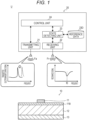
- Fig. 1 is a diagram illustrating a basic configuration of a detecting system U according to the present disclosure.
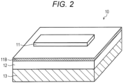
- Fig. 2 is a diagram illustrating a basic configuration of a sensor 10 according to the present disclosure.
- the detecting system U includes: a sensor 10 that has predetermined reflection characteristics with respect to electromagnetic waves (the characteristics will be hereinafter referred to simply as the "reflection characteristics of the sensor 10"); and a reader 20 that detects the reflection characteristics of the sensor 10 by receiving reflected waves Fr from the sensor 10 when electromagnetic waves Fa having a predetermined frequency are transmitted to the sensor 10.
- the reader 20 is disposed in a fixed state at a position approximately several meters away from the sensor 10, so as to face the front surface of the sensor 10, for example.
- the detecting system U detects a state change in the sensor 10 (which is an environmental change to be detected by the sensor 10), on the basis of a change in the reflection characteristics of the sensor 10.
- the sensor 10 includes an antenna unit 11, an isolation layer 12, and aback surface reflector 13 in this order from the front surface side.
- the antenna unit 11 is a metal pattern formed on a base material 11B.
- the antenna unit 11 is formed with a metal pattern in a strip-like shape, for example, and has a resonance structure that resonates when electromagnetic waves Fa having a predetermined frequency are emitted.
- the antenna unit 11 then absorbs the electromagnetic waves Fa having the frequency that matches its own resonance frequency (when the frequency of the electromagnetic waves Fa is f0 in Fig. 1 ), for example. In a case where electromagnetic waves Fa having some other frequency are emitted, the antenna unit 11 reflects the electromagnetic waves Fa.
- the resonance frequency of the antenna unit 11 is determined by the shape (mainly the length) of the metal pattern forming the antenna unit 11. Normally, when the maximum length of the antenna is 1/2 ⁇ of the frequency of the electromagnetic waves, the antenna resonates, and an absorption peak at which the intensity of the reflected waves at the frequency corresponding to the antenna length becomes lower appears.
- the antenna unit 11 may be formed only with one antenna element, but the antenna unit 11 is preferably formed with a plurality of antenna elements to increase the intensity of reflected waves Fr.
- the antenna unit 11 is preferably formed with a plurality of antenna elements having different lengths from one other, for example, so that the sensor 10 has a plurality of resonance frequencies. With this arrangement, the accuracy of the reader 20 detecting the reflection characteristics of the sensor 10 can be increased.
- the method for forming the antenna unit 11 on the base material 11B may be any appropriate method such as a printing method. Further, a metal material such as copper, silver, gold, or aluminum is used as the material of the antenna unit 11. Note that, in a case where the antenna unit 11 is to have elasticity, it is desirable to use a metal material containing a binder or the like as the material of the antenna unit 11.
- the base material 11B on which the antenna unit 11 is formed a material having electromagnetic wave permeability such as paper or resin is used.
- the form of the base material 11B is not limited to a plate-like shape, and may be a curved shape, a tubular shape, or the like.
- the antenna unit 11 may be formed directly on an article such as a packaging material or a container.
- the base material 11B may be an object to be detected by the sensor 10.
- the isolation layer 12 is an insulating material or a space in which any object is not disposed.
- the isolation layer 12 is disposed between the antenna unit 11 and the back surface reflector 13, to insulate the antenna unit 11 and the back surface reflector 13 from each other.
- the resonance phenomenon is further amplified in a case where a space (filled with air) in which any object is not disposed, or a low-dielectric constant material such as a foamed resin is used.
- a space filled with air
- a low-dielectric constant material such as a foamed resin
- the back surface reflector 13 is disposed so as to face the antenna unit 11 via the isolation layer 12, and reflects the electromagnetic waves Fa emitted onto the sensor 10. In a plan view, the back surface reflector 13 is disposed over a wider region than the region in which the antenna unit 11 is formed, at a position facing the antenna unit 11, for example.
- the back surface reflector 13 also functions to amplify the resonance phenomenon that occurs in the antenna unit 11. Specifically, in a case where the back surface reflector 13 is present, a resonance phenomenon that occurs in the antenna unit 11 also occurs between the antenna unit 11 and the back surface reflector 13, and the resonance phenomenon is amplified. That is, the back surface reflector 13 heightens the resonance peak in a case where a resonance phenomenon occurs in the antenna unit 11.
- the back surface reflector 13 is disposed at a position in which the distance from the antenna unit 11 is 0.01 mm to 1000 mm, for example. Within this range, an electromagnetic field easily appears between the antenna unit 11 and the back surface reflector 13, and the resonance phenomenon in the sensor 10 can be effectively amplified.
- the contrast of the intensity of reflected waves Fr can be increased between the reflected waves Fr generated by the sensor 10 at the time of resonance and the reflected waves Fr generated by the sensor 10 at the time of nonresonance.
- the resonance phenomenon is amplified.
- the resonance peak greatly varies with changes in such characteristics that reflect electromagnetic waves due to changes in the area of the back surface reflector 13 in the region facing the antenna unit 11.
- the senor 10 is designed so that the state of the antenna unit 11, the isolation layer 12, or the back surface reflector 13 is linked to changes in the state of the detection target (this aspect will be described later in detail).
- the sensor 10 then causes the reader 20 to detect a change in the state of the detection target from a change in the reflection characteristics of the reflected waves Fr generated when the electromagnetic waves Fa are emitted from the reader 20.
- the reflection characteristics of the sensor 10 indicating the state of the detection target are typically determined by the intensity of the reflected waves Fr generated from the sensor 10 when the electromagnetic waves Fa are emitted from the reader 20, or by the resonance frequency of the sensor 10.
- the reader 20 includes a transmitting unit 21, a receiving unit 22, a state detecting unit 23, and a control unit 24.
- the transmitting unit 21 transmits electromagnetic waves Fa having a predetermined frequency to the sensor 10.
- the transmitting unit 21 includes a transmitting antenna, an oscillator, and the like, for example.
- the transmitting unit 21 transmits sinusoidal electromagnetic waves Fa having its peak intensity at a single frequency, for example.
- the transmitting unit 21 then temporally changes the transmission frequency of the electromagnetic waves Fa to be transmitted from the transmitting antenna, and performs a frequency sweep within a predetermined frequency band.
- the resonance frequency of the sensor 10 matches the transmission frequency of the electromagnetic waves Fa to be transmitted by the transmitting unit 21, the resonance frequency of the sensor 10 is detected as a change in the intensity of the reflected waves Fr generated by the sensor 10.
- the frequency band of the electromagnetic waves Fa to be transmitted by the transmitting unit 21 is a millimeter wave band or a gigahertz frequency band, for example.
- the receiving unit 22 receives the reflected waves Fr generated from the sensor 10 when the transmitting unit 21 transmits the electromagnetic waves Fa.
- the receiving unit 22 includes a receiving antenna, a network analyzer, and the like, for example.
- the receiving unit 22 then detects the reflection characteristics of the sensor 10, using an S parameter determined from the intensity of the reflected waves Fr and the like.
- the state detecting unit 23 compares the reflection characteristics of the sensor 10 obtained from the reflected waves Fr received by the receiving unit 22 at the present time with the reflection characteristics of the sensor 10 stored beforehand as reference data 23D, and detects the state of the sensor 10 on the basis of the result of the comparison. For example, on the basis of the above comparison result, the state detecting unit 23 calculates the degree of change in the resonance frequency of the sensor 10 or the intensity of the reflected waves Fr generated by the sensor 10 at the present time, from the value indicated by the reference data 23D. By doing so, the state detecting unit 23 detects the state of the sensor 10.
- the reference data 23D is data for converting the reflection characteristics of the sensor 10 at the present time into the state of the sensor 10 at the present time (which is the state of the object as the detection target).
- the reference data 23D is only required to be data that associates the state of the sensor 10 with the reflection characteristics of the sensor 10, and may be set on the basis of the pre-acquired reflection characteristics of the sensor 10, or may be set on the basis of the reflection characteristics of the sensor 10 detected earlier than the present time.
- information about the intensity of the reflected waves of each frequency is stored as information about the reflection characteristics of the sensor 10, for example. Further, in the reference data 23D, the shift amount of the resonance frequency of the sensor 10 and the amount of state change in the detection target are stored in association with each other, for example. Also, in the reference data 23D, the amount of change in the reflected wave intensity at the resonance frequency of the sensor 10 and the amount of state change the detection target are stored in association with each other, for example.
- the control unit 24 controls the reader 20 in a comprehensive manner. Note that, to successively monitor the state of the object as the detection target, the control unit 24 causes the transmitting unit 21, the receiving unit 22, and the state detecting unit 23 to perform the processing described above at predetermined intervals, for example.
- the transmitting unit 21, the receiving unit 22, the state detecting unit 23, and the control unit 24 are formed with a CPU, a ROM, a RAM, and the like, for example. Part or all of the transmitting unit 21, the receiving unit 22, the state detecting unit 23, and the control unit 24 described above is then formed by the CPU referring to a control program and various kinds of data. However, part or all of each function may be realized by processing performed by a DSP or processing performed by a dedicated hardware circuit (an ASIC, for example), instead of processing performed by a CPU.
- Figs. 3 and 4 are diagrams illustrating the configuration of a sensor 10 according to a first embodiment.
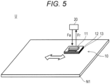
- Fig. 5 is a diagram illustrating an example configuration of a detecting system U according to the first embodiment.
- the sensor 10 is mounted on the detection target object in an expandable manner.
- a reader 20 detects a change in the resonance frequency of the sensor 10 or a change in the intensity of reflected waves Fr from the sensor 10 due to expansion or contraction of an antenna unit 11.
- Fig. 3A illustrates a mode in which the antenna unit 11 expands and contracts in the longitudinal direction.
- Fig. 3B schematically illustrates a mode of change in the reflection characteristics of the sensor 10 in a case where the antenna unit 11 contracts in the longitudinal direction.
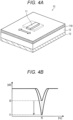
- Fig. 4A illustrates a mode in which the antenna unit 11 expands and contracts in the width direction.
- Fig. 4B schematically illustrates a mode of change in the reflection characteristics of the sensor 10 in a case where the antenna unit 11 expands in the width direction.
- the resonance frequency of the sensor 10 shifts from the resonance frequency prior to the expansion or contraction to the resonance frequency corresponding to the length of the antenna unit 11.
- the resonance frequency of the sensor 10 shifts to the low frequency side (shifts from frequency f0 to frequency f1 as shown in Fig. 3B , for example).
- the area of the antenna unit 11 facing the back surface reflector 13 changes, and accordingly, the intensity of the reflected waves Fr from the sensor 10 changes from the intensity prior to the expansion or contraction.
- the intensity of the reflected waves Fr from the sensor 10 increases (increases from intensity I0 to intensity I1 as shown in Fig. 4B , for example).
- the reader 20 can detect a change in the shape of the object to which the sensor 10 is attached, by detecting the reflection characteristics (the resonance frequency or the intensity) of the sensor 10 when the electromagnetic waves Fa are transmitted to the sensor 10.
- the reader 20 detects expansion or contraction of the antenna unit 11, by comparing the detected reflection characteristics of the sensor 10 with the reflection characteristics of the sensor 10 stored in the reference data 23D. That is, with the detecting system U according to this embodiment, a shape change detecting system can be formed, for example.
- the antenna unit 11, the isolation layer 12, and the back surface reflector 13 are each made of a stretchable material, for example, so that the sensor 10 can expand and contract in accordance with expansion and contraction of an object N1.
- the antenna unit 11 may be formed directly on the front surface of the object N1 to be detected, and the back surface reflector 13 may be disposed on the back surface side of the object N1 to be detected. In that case, only the antenna unit 11 needs to be expandable and contractible.
- the isolation layer 12 and the back surface reflector 13 are designed not to have any state change, so that the reflection characteristics of the sensor 10 do not vary with changes in components other than expansion and contraction of the antenna unit 11.
- Figs. 6 and 7 are diagrams illustrating the configuration of a detecting system U according to a modification of this embodiment.
- a detecting antenna unit 11X is provided so as to face the antenna unit 11 of a sensor 10, and misalignment is detected between the base material 11B on which the antenna unit 11 is formed and a base material 11BX on which the detecting antenna unit 11X is formed.
- the reader 20 detects a change in the reflection characteristics of the sensor 10, the change being caused by a change in the area of the region in which the antenna unit 11 and the detecting antenna unit 11X face each other.
- Figs. 6A and 6B illustrate a mode in which the positional relationship between the antenna unit 11 and the detecting antenna unit 11X shifts in the width direction of the antenna unit 11.
- the upper drawing and the lower drawing show a side view and a plan view of the detecting system U, respectively.
- a change in the positional relationship between the antenna unit 11 and the detecting antenna unit 11X appears as a change in the intensity of reflected waves Fr from the sensor 10 as in the mode illustrated in Fig. 4 .
- Figs. 7A and 7B illustrate a mode in which the positional relationship between the antenna unit 11 and the detecting antenna unit 11X shifts in the longitudinal direction of the antenna unit 11.
- the upper drawing and the lower drawing show a side view and a plan view of the detecting system U, respectively.
- a change in the positional relationship between the antenna unit 11 and the detecting antenna unit 11X appears as a change in the resonance frequency of the sensor 10 as in the mode illustrated in Fig. 3 .
- the position of the base material 11B or the base material 11BX is set as the detection target, and the position of the base material 11B or the base material 11BX can be detected from a change in the reflection characteristics of the sensor 10.
- Fig. 8 is a diagram illustrating the configuration of a sensor 10 according to a second embodiment.
- Fig. 9 is a diagram illustrating an example configuration of a detecting system U according to the second embodiment.
- an isolation layer 12 is designed so that the detection target object can move in and out of the isolation layer 12.
- the isolation layer 12 is formed with a space communicating with the outside, for example, and is disposed so that the detection target object can move in and out of the space.
- the detection target object that enters and exits the isolation layer 12 is not necessarily a solid material, but may be a liquid material or a particulate material.
- a reader 20 detects a change in the dielectric constant of the isolation layer 12 in a case where an object is carried into or penetrates into the isolation layer 12, or an object is carried out or flows out from the isolation layer 12. At this stage, the change in the dielectric constant of the isolation layer 12 is detected as a change in the resonance frequency of the sensor 10.
- Fig. 8A illustrates a mode in which the dielectric constant of the isolation layer 12 changes.
- Fig. 8B schematically illustrates a mode of change in the reflection characteristics of the sensor 10 in a case where the dielectric constant of the isolation layer 12 becomes higher.
- the resonance frequency of the antenna unit 11 changes due to a wavelength shortening effect of the isolation layer 12. Therefore, the resonance frequency of the sensor 10 shifts to the resonance frequency corresponding to the dielectric constant of the isolation layer 12. It is known that such a wavelength shortening effect normally becomes greater as the dielectric constant of the dielectric material adjacent to the antenna unit 11 becomes higher. Therefore, in a case where the dielectric constant of the isolation layer 12 becomes higher, for example, the resonance frequency of the sensor 10 shifts to the low frequency side (shifts from frequency f0 to frequency f1 as shown in Fig. 8B , for example).
- the reader 20 can detect a state change in the isolation layer 12 by detecting the reflection characteristics (the resonance frequency or the intensity) of the sensor 10.
- Figs. 9A and 9B illustrate a mode in which the isolation layer 12 is designed as a storage space for accommodating an object (a medicine bag, for example) N2, as an example of a detecting system U according to this embodiment.
- the reader 20 detects a state change in which the object N2 in the storage space formed by the isolation layer 12 decreases in the isolation layer 12 (a decrease in the amount of medicine in the medicine bag, for example).
- the reader 20 detects the ratio between the detection target object and air in the isolation layer 12 as a dielectric constant.
- a product management system can be formed, for example.
- the antenna unit 11 and the back surface reflector 13 are designed not to have any state change, so that the reflection characteristics of the sensor 10 do not vary with changes in components other than changes in the dielectric constant of the isolation layer 12.
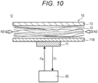
- Fig. 10 is a diagram illustrating the configuration of a detecting system U according to a first modification.
- the detecting system U according to the first modification differs from the above embodiment in that the detection target is a liquid N3 that penetrates into the isolation layer 12.
- the isolation layer 12 is made of a liquid absorber, and the liquid N3 from the surroundings of the sensor 10 can penetrate into the isolation layer 12. From a change in the dielectric constant of the isolation layer 12 (the liquid absorber in this modification), the reader 20 according to this modification then detects a state in which the liquid N3 has penetrated into the isolation layer 12.
- Fig. 11 is a diagram illustrating the configuration of a detecting system U according to a second modification.
- the detecting system U according to the second modification differs from the above embodiment in that the detection target is the density of a particulate material N4 flowing in the isolation layer 12.
- the isolation layer 12 is formed as a space in a pipe through which gas flows.
- the antenna unit 11 and the back surface reflector 13 of the sensor 10 are disposed on one side and the other side, with the space in the pipe being interposed in between.
- the reader 20 according to this modification detects a change in the dielectric constant of the isolation layer 12, on the basis of a change in the resonance frequency of reflected waves Fr from the sensor 10. From the change in the dielectric constant of the isolation layer 12, the reader 20 according to this modification then detects the density of the particulate material N4 flowing in the isolation layer 12.
- Fig. 12 is a diagram illustrating the configuration of a sensor 10 according to a third embodiment.
- Fig. 13 is a diagram illustrating an example configuration of a detecting system U according to the third embodiment.
- the thickness of an isolation layer 12 (which is the distance between an antenna unit 11 and a back surface reflector 13) is designed to be variable.
- the antenna unit 11 and the back surface reflector 13 are designed to change their positions with a change in the thickness of the object.
- a reader 20 detects a change in the intensity of reflected waves Fr from the sensor 10, the change accompanying a change in the thickness of the isolation layer 12.
- Fig. 12A illustrates a mode in which the thickness of the isolation layer 12 changes.
- Fig. 12B schematically illustrates a mode of change in the reflection characteristics of the sensor 10 in a case where the thickness of the isolation layer 12 becomes greater.
- the degree of a resonance phenomenon between the antenna unit 11 and the back surface reflector 13 changes.
- the degree of such a resonance phenomenon is normally maximized when the distance between the antenna unit 11 and the back surface reflector 13 is a predetermined distance.
- the degree of such a resonance phenomenon becomes lower as the distance between the antenna unit 11 and the back surface reflector 13 increases from the predetermined distance.
- the intensity of the reflected waves Fr from the sensor 10 becomes higher (increases from intensity I0 to intensity I1 as shown in Fig. 12B , for example).
- the reader 20 can detect the thickness of the isolation layer 12 (the liquid level of the liquid in this case) by detecting the reflection characteristics (the intensity of the reflected waves Fr in this case) of the sensor 10.
- Fig. 13 illustrates a mode in which the isolation layer 12 is formed with a liquid N5 filling a container, as an example of a detecting system U according to this embodiment.
- the antenna unit 11 of the sensor 10 is then disposed in a floating state on the surface of the liquid N5 filling the container, and the back surface reflector 13 is disposed on the bottom surface of the container.
- the reader 20 From a change in the intensity of reflected waves Fr from the sensor 10, the reader 20 detects the thickness of the isolation layer 12, which is the liquid level of the liquid N5 that fills the isolation layer 12. That is, with the detecting system U according to this embodiment, a liquid level management system can be formed, for example.
- the antenna unit 11 and the back surface reflector 13 are designed not to have any state change, so that the reflection characteristics of the sensor 10 do not vary with changes in components other than changes in the thickness of the isolation layer 12.
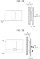
- Figs. 14 and 15 are diagrams illustrating the configuration of a sensor 10 according to a fourth embodiment.
- Fig. 16 is a diagram illustrating an example configuration of a detecting system U according to the fourth embodiment.
- the back surface reflector 13 of the sensor 10 is attached to the detection target object, and the area of the region facing the antenna unit 11 is designed to be variable depending on the position of the detection target object (the region facing the antenna unit 11 includes the region on the opposite side from the antenna unit 11 and its surrounding region, and will be hereinafter referred to as the "antenna facing region").
- a reader 20 detects a change in the area of the antenna facing region of the back surface reflector 13 of the sensor 10, on the basis of a change in the intensity of reflected waves Fr from the sensor 10.
- Fig. 14A illustrates a mode in which the area of the antenna facing region of the back surface reflector 13 changes, as part of the back surface reflector 13 is cut off.
- Fig. 14B schematically illustrates a mode of change in the reflection characteristics of the sensor 10 in a case where the area of the antenna facing region of the back surface reflector 13 decreases.
- Fig. 15A illustrates a mode in which the area of the antenna facing region of the back surface reflector 13 changes, as the back surface reflector 13 moves.
- Fig. 15B schematically illustrates a mode of change in the reflection characteristics of the sensor 10 in a case where the area of the antenna facing region of the back surface reflector 13 increases.
- the resonance phenomenon between the antenna unit 11 and the back surface reflector 13 weakens. Therefore, the degree of electromagnetic wave absorption by the sensor 10 weakens. In such a case, the intensity of the reflected waves Fr of the sensor 10 increases (increases from intensity I0 to intensity I1 as shown in Fig. 14B , for example).
- the reader 20 can detect a state change in the back surface reflector 13, by detecting the intensity of the reflected waves Fr from the sensor 10.
- Figs. 16A and 16B illustrate, as an example of a detecting system U according to this embodiment, a mode in which the back surface reflector 13 of the sensor 10 is formed integrally with detection target objects (individual medicines, for example) N6, and the back surface reflector 13 is designed to be detachable together with the detection target objects N6.
- the reader 20 detects the number of detection target objects N6 detached from the sensor 10, on the basis of a change in the intensity of reflected waves Fr from the sensor 10. That is, with the detecting system U according to this embodiment, a medication management system can be formed, for example.
- the antenna unit 11 and the isolation layer 12 are designed not to have any state change, so that the reflection characteristics of the sensor 10 do not vary with changes in components other than the area of the antenna facing region of the back surface reflector 13.
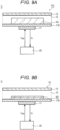
- Fig. 17 is a diagram illustrating an example configuration of a detecting system U according to a fifth embodiment.
- the detecting system U includes a plurality of sensors 10a, 10b, and 10c having resonance frequencies different from one another, and a reader 20 that detects state changes in the sensors 10a, 10b, and 10c separately from one another.
- Each sensor (10a, 10b, or 10c in this case) is designed to have a different resonance frequency from the other sensors (10a, 10b, or 10c in this case) through adjustment of the lengths of antenna units 11a, 11b, and 11c in the longitudinal direction, for example. That is, each of the sensors 10a, 10b, and 10c has its resonance frequency forming identification information for distinguishing itself from the other sensors (10a, 10b, or 10c in this case). Each of the sensors 10a, 10b, and 10c then detects its state change.
- Each of the sensors 10a, 10b, and 10c according to this embodiment has the same configuration as the sensor 10 described in the fourth embodiment.
- the sensors 10a, 10b, and 10c are then provided for a plurality of detection target objects (medicines, for example) N7, N8, and N9, respectively, so that detached states of the respective detection target objects N7, N8, and N9 can be monitored.
- the sensors 10a, 10b, and 10c share the isolation layer 12 and the base material 11B, and include the antenna units 11a, 11b, and 11c, respectively, and back surface reflectors 13a, 13b, and 13c, respectively.
- the reader 20 emits electromagnetic waves Fa to the sensors 10a, 10b, and 10c, and detects the reflection characteristics of each of the sensors 10a, 10b, and 10c.
- the reader 20 compares the detected reflection characteristics of the respective sensors 10a, 10b, and 10c with the reflection characteristics of the sensors 10a, 10b, and 10c indicated by the reference data 23D, and detects the state of each of the sensors 10a, 10b, and 10c.
- the reader 20 identifies the states of the respective sensors 10a, 10b, and 10c, on the basis of the resonance frequencies of the respective sensors 10a, 10b, and 10c. That is, in a case where any one of the sensors 10a, 10b, and 10c is detached, the reader 20 detects a state in which the intensity of the reflected waves Fr at the resonance frequency corresponding to that sensor drops.
- the state of each of the detection target objects can be individually managed with one reader 20, for example.
- a detecting system U includes: a sensor 10 that includes an antenna unit 11 formed with a metal pattern, and a back surface reflector 13 that faces the antenna unit 11 via an isolation layer 12; and a reader 20 that transmits electromagnetic waves Fa to the sensor 10, receives reflected waves Fr from the sensor 10, and compares the reflection characteristics of the sensor 10 detected from the reflected waves Fr with the reflection characteristics of the sensor 10 stored in advance, to detect a state change in the sensor 10.
- a change in the reflection characteristics of the sensor 10 can be detected with high accuracy.
- a state change in the object to be detected by the sensor 10, or an environmental change in the surroundings of the object can be detected with high accuracy.
- a detecting system U may detect a state in which part of the antenna unit 11 is peeled off, or a state in which the antenna unit 11 is attached thereto.
- a detecting system U may detect a change in the material forming the isolation layer 12 or a change in the material forming the back surface reflector 13.
- the antenna unit 11 that is used in a detecting system U may be of a type that reflects electromagnetic waves Fa when electromagnetic waves Fa having the frequency that matches the resonance frequency of the antenna unit 11 are emitted, and absorbs electromagnetic waves Fa having some other frequency.
- the back surface reflector 13 is disposed at a position 0.01 mm to 1000 mm away from the antenna unit 11, for example. Within this range, the back surface reflector 13 functions to amplify the reflected waves generated at the antenna unit 11.
- a state change in an object or an environmental change in the surroundings of an object can be detected with high accuracy.
Landscapes
- Physics & Mathematics (AREA)
- Engineering & Computer Science (AREA)
- General Physics & Mathematics (AREA)
- Theoretical Computer Science (AREA)
- Health & Medical Sciences (AREA)
- Toxicology (AREA)
- Electromagnetism (AREA)
- General Health & Medical Sciences (AREA)
- Artificial Intelligence (AREA)
- Computer Vision & Pattern Recognition (AREA)
- Geophysics And Detection Of Objects (AREA)
- Length-Measuring Devices Using Wave Or Particle Radiation (AREA)
Claims (10)
- Ein Detektionssystem, umfassend:einen Sensor (10) umfassend: eine Antenneneinheit (11), die mit einem Metallmuster ausgebildet ist; und einen Rückseitenreflektor (13), der der Antenneneinheit (11) über eine Isolationsschicht (12) zugewandt ist; undeinen Leser (20), der elektromagnetische Wellen (Fa) an den Sensor (10) sendet, von dem Sensor (10) reflektierte Wellen (Fr) empfängt und Reflexionseigenschaften des Sensors (10), die von den reflektierten Wellen (Fr) detektiert werden, mit im Voraus gespeicherten Reflexionseigenschaften des Sensors (10) vergleicht, um eine Zustandsänderung in dem Sensor (10) zu detektieren,
wobei der Sensor (10) so ausgebildet ist, dass einer von einem Zustand der Antenneneinheit (11), einem Zustand der Isolationsschicht (12) oder einem Zustand des Rückseitenreflektors (13) mit einem Zustand eines Detektionsziels verknüpft ist, und wobeider Leser (20) eine Zustandsänderung des Detektionsziels detektiert, indem er die aus den reflektierten Wellen (Fr) detektierten Reflexionseigenschaften des Sensors (10) mit den im Voraus gespeicherten Reflexionseigenschaften des Sensors (10) vergleicht. - Detektionssystem nach Anspruch 1, wobei
der Leser (20) die elektromagnetischen Wellen (Fa) an den Sensor (10) sendet, während er die Sendefrequenz zeitlich ändert, um einen Sweep mit der Sendefrequenz durchzuführen. - Detektionssystem nach Anspruch 1 oder 2, wobei
der Leser (20) eine Zustandsänderung des Sensors (10) detektiert, indem er eine aus den reflektierten Wellen (Fr) ermittelte Resonanzfrequenz des Sensors (10) mit einer im Voraus gespeicherten Resonanzfrequenz des Sensors (10) vergleicht. - Detektionssystem nach einem der Ansprüche 1 bis 3, wobei
der Leser (20) eine Zustandsänderung des Sensors (10) detektiert, indem er eine Intensität der reflektierten Wellen (Fr) mit einer Intensität der reflektierten Wellen (Fr), die durch die im Voraus gespeicherten Reflexionseigenschaften des Sensors (10) angegeben wird, vergleicht. - Detektionssystem nach einem der Ansprüche 1 bis 4, wobeidie Antenneneinheit (11) in einem dehnbaren Zustand an einem Objekt als Detektionsziel angebracht ist, undder Leser (20) eine Änderung eines gedehnten Zustands des Objekts anhand einer Änderung eines gedehnten Zustands der Antenneneinheit (11) detektiert.
- Detektionssystem nach einem der Ansprüche 1 bis 4, wobeidie Isolierschicht (12) so ausgebildet ist, dass sich ein Objekt als Detektionsziel in die Isolierschicht (12) hinein und aus ihr heraus bewegt, undder Leser (20) eine Änderung der Häufigkeit oder Häufigkeitsdichte des Objekts in der Isolationsschicht (12) anhand einer Änderung einer Dielektrizitätskonstante der Isolationsschicht (12) detektiert.
- Detektionssystem nach einem der Ansprüche 1 bis 4, wobeidie Antenneneinheit (11) oberhalb oder unterhalb eines Objekts als Detektionsziel so ausgebildet ist, dass sie ihre Position mit einer Änderung der Dicke des Objekts ändert beziehungsweise der Rückseitenreflektor (13) oberhalb oder unterhalb des Objekts als Detektionsziel so ausgebildet ist, dass er seine Position mit einer Änderung der Dicke des Objekts ändert, undder Leser (20) eine Änderung der Dicke des Objekts anhand einer Änderung erfasst, die in einem Resonanzphänomen in der Antenneneinheit (11) durch eine Änderung des Abstands zwischen der Antenneneinheit (11) und dem Rückseitenreflektor (13) verursacht wird.
- Detektionssystem nach einem der Ansprüche 1 bis 4, wobeider Rückseitenreflektor (13) an einem Objekt als Detektionsziel angebracht ist, undder Leser (20) eine Änderung einer Position des Objekts aus einer Änderung detektiert, die in einem Resonanzphänomen in der Antenneneinheit (11) durch eine Änderung in einem Bereich des Rückseitenreflektors (13) in einem der Antenneneinheit (11) zugewandten Bereich verursacht wird.
- Detektionssystem nach einem der Ansprüche 1 bis 8, umfassendeine Vielzahl der Sensoren (10a, 10b, 10c) mit voneinander verschiedenen Resonanzfrequenzen,wobei der Leser (20) Zustandsänderungen der jeweiligen Sensoren (10a, 10b, 10c) getrennt voneinander anhand der Resonanzfrequenzen der jeweiligen Sensoren (10a, 10b, 10c) detektiert.
- Detektionssystem nach einem der Ansprüche 1 bis 9, wobei
der Leser umfasst:eine Sendeeinheit (21), die elektromagnetische Wellen (Fa) an den Sensor (10) sendet;eine Empfangseinheit (22), die reflektierte Wellen (Fr) von dem Sensor (10) empfängt, wobei die reflektierten Wellen (Fr) erzeugt werden, wenn die Sendeeinheit (21) die elektromagnetischen Wellen (Fa) sendet; undeine Zustandserkennungseinheit (23), die eine Zustandsänderung in dem Sensor (10) detektiert, indem sie Reflexionseigenschaften des Sensors (10), die aus den von der Empfangseinheit (22) empfangenen reflektierten Wellen (Fr) ermittelt werden, mit im Voraus gespeicherten Reflexionseigenschaften des Sensors (10) vergleicht.
Applications Claiming Priority (2)
| Application Number | Priority Date | Filing Date | Title |
|---|---|---|---|
| JP2018207687 | 2018-11-02 | ||
| PCT/JP2019/042609 WO2020090904A1 (ja) | 2018-11-02 | 2019-10-30 | 検出システム、及びリーダー |
Publications (3)
| Publication Number | Publication Date |
|---|---|
| EP3876153A1 EP3876153A1 (de) | 2021-09-08 |
| EP3876153A4 EP3876153A4 (de) | 2022-03-02 |
| EP3876153B1 true EP3876153B1 (de) | 2023-08-30 |
Family
ID=70463744
Family Applications (1)
| Application Number | Title | Priority Date | Filing Date |
|---|---|---|---|
| EP19878052.0A Active EP3876153B1 (de) | 2018-11-02 | 2019-10-30 | Detektionssystem und lesegerät |
Country Status (5)
| Country | Link |
|---|---|
| US (1) | US11630963B2 (de) |
| EP (1) | EP3876153B1 (de) |
| JP (1) | JP7405092B2 (de) |
| CN (1) | CN113039558B (de) |
| WO (1) | WO2020090904A1 (de) |
Families Citing this family (6)
| Publication number | Priority date | Publication date | Assignee | Title |
|---|---|---|---|---|
| EP3876153B1 (de) * | 2018-11-02 | 2023-08-30 | Konica Minolta, Inc. | Detektionssystem und lesegerät |
| US20230147767A1 (en) * | 2020-04-24 | 2023-05-11 | Konica Minolta, Inc. | State detection system |
| AU2021266748A1 (en) | 2020-05-07 | 2022-12-08 | Becton, Dickinson And Company | Device, system, and method for detection of medical device components and/or mating thereof |
| WO2022239427A1 (ja) * | 2021-05-10 | 2022-11-17 | コニカミノルタ株式会社 | 状態検出システム |
| WO2022239425A1 (ja) * | 2021-05-10 | 2022-11-17 | コニカミノルタ株式会社 | 状態検出システム |
| WO2022254853A1 (ja) * | 2021-06-03 | 2022-12-08 | コニカミノルタ株式会社 | 検査システム、及び検査方法 |
Family Cites Families (16)
| Publication number | Priority date | Publication date | Assignee | Title |
|---|---|---|---|---|
| JPH1125370A (ja) * | 1997-07-04 | 1999-01-29 | Sensor Technos Kk | 定置物品監視装置 |
| JP2001161732A (ja) * | 1999-09-27 | 2001-06-19 | Matsushita Electric Works Ltd | おむつ交換頃合センサー及びおむつ交換頃合検知装置 |
| JP2001134726A (ja) | 1999-11-01 | 2001-05-18 | Sensor Technos Kk | サニタリー用センサーシステム |
| JP4164423B2 (ja) * | 2003-08-29 | 2008-10-15 | キヤノン株式会社 | センシング部とポインティングデバイスとを含み構成される装置 |
| JP4747750B2 (ja) * | 2005-09-13 | 2011-08-17 | 大日本印刷株式会社 | 環境変化検知システム |
| JP2007110256A (ja) * | 2005-10-11 | 2007-04-26 | Matsushita Electric Ind Co Ltd | フェーズドアレイアンテナ |
| JP2011058836A (ja) * | 2009-09-07 | 2011-03-24 | Alps Electric Co Ltd | 無線センサ装置 |
| JP6144620B2 (ja) * | 2010-04-08 | 2017-06-07 | アクセス ビジネス グループ インターナショナル リミテッド ライアビリティ カンパニー | POS(pointofsale)誘導性システムと方法 |
| JP2015017835A (ja) * | 2013-07-09 | 2015-01-29 | 京セラ株式会社 | 距離センサおよび浴室用異常報知システム |
| WO2015168700A1 (en) * | 2014-05-02 | 2015-11-05 | The Board Of Trustees Of The Leland Stanford Junior University | Method and apparatus for tracing motion using radio frequency signals |
| AU2015301198A1 (en) * | 2014-08-04 | 2017-03-02 | Avery Dennison Corporation | Time-temperature tracking label |
| EP3184030A4 (de) * | 2014-08-22 | 2017-12-06 | Fujitsu Limited | Zustandsbeurteilungsverfahren, zustandsbeurteilungssystem, bekleidung und überwachungssystem |
| KR20170106837A (ko) * | 2016-03-14 | 2017-09-22 | 엘지전자 주식회사 | 요당 검출용 전계효과 트랜지스터 |
| KR20180071802A (ko) * | 2016-12-20 | 2018-06-28 | 삼성전자주식회사 | 이미지 센서 |
| JP6951127B2 (ja) | 2017-06-06 | 2021-10-20 | 東日本旅客鉄道株式会社 | 自動列車防護システム |
| EP3876153B1 (de) * | 2018-11-02 | 2023-08-30 | Konica Minolta, Inc. | Detektionssystem und lesegerät |
-
2019
- 2019-10-30 EP EP19878052.0A patent/EP3876153B1/de active Active
- 2019-10-30 CN CN201980070504.1A patent/CN113039558B/zh active Active
- 2019-10-30 WO PCT/JP2019/042609 patent/WO2020090904A1/ja not_active Ceased
- 2019-10-30 US US17/283,637 patent/US11630963B2/en active Active
- 2019-10-30 JP JP2020553985A patent/JP7405092B2/ja active Active
Also Published As
| Publication number | Publication date |
|---|---|
| US20210390274A1 (en) | 2021-12-16 |
| JPWO2020090904A1 (ja) | 2021-09-30 |
| CN113039558B (zh) | 2023-11-03 |
| EP3876153A4 (de) | 2022-03-02 |
| CN113039558A (zh) | 2021-06-25 |
| US11630963B2 (en) | 2023-04-18 |
| EP3876153A1 (de) | 2021-09-08 |
| JP7405092B2 (ja) | 2023-12-26 |
| WO2020090904A1 (ja) | 2020-05-07 |
Similar Documents
| Publication | Publication Date | Title |
|---|---|---|
| EP3876153B1 (de) | Detektionssystem und lesegerät | |
| Subrahmannian et al. | Chipless RFID: A unique technology for mankind | |
| US10402604B2 (en) | Radio-frequency identification tags | |
| US8556184B2 (en) | Chipless passive RFID tag | |
| Borgese et al. | An inkjet printed chipless RFID sensor for wireless humidity monitoring | |
| RU2568942C2 (ru) | Антенна для влажной среды | |
| US10871151B2 (en) | Method for detecting icing and de-icing | |
| US20130119135A1 (en) | Bi-directional and multi-frequency rf signaling system | |
| Zhu et al. | Compact, flexible harmonic transponder sensor with multiplexed sensing capabilities for rapid, contactless microfluidic diagnosis | |
| US8786441B2 (en) | Radio frequency identification tag | |
| EP4024277B1 (de) | Etikett | |
| US20160253534A1 (en) | Article management system and article management method | |
| Habib et al. | Directly printable compact chipless RFID tag for humidity sensing | |
| Wang et al. | Design of a metamaterial chipless RFID sensor tag for high temperature | |
| CN115986392A (zh) | 一种组合式贴片天线传感器及传感系统 | |
| Grosinger et al. | Sensor add-on for batteryless UHF RFID tags enabling a low cost IoT infrastructure | |
| Perret et al. | Chipless RFID tags for passive wireless sensor grids | |
| JP6135358B2 (ja) | アンテナ及びアンテナの製造方法 | |
| WO2008118019A2 (en) | Transponder system | |
| US20020080089A1 (en) | Antenna arrangement and a communication arrangement comprising the same | |
| Tedjini et al. | Radio-frequency identification systems and advances in tag design | |
| Gu et al. | Design of a metamaterial chipless RFID sensor tag for high temperature | |
| Fantuzzi et al. | Low-cost UHF near-field power transmission for RFID applications | |
| Khan et al. | Orientation Independent, Polarization Insensitive High-Density Flexible Chipless RFID Tag for IoT Applications | |
| Alrawashdeh | A Flexible Loop Sensor Antenna for Ice and Frost Detection |
Legal Events
| Date | Code | Title | Description |
|---|---|---|---|
| STAA | Information on the status of an ep patent application or granted ep patent |
Free format text: STATUS: THE INTERNATIONAL PUBLICATION HAS BEEN MADE |
|
| PUAI | Public reference made under article 153(3) epc to a published international application that has entered the european phase |
Free format text: ORIGINAL CODE: 0009012 |
|
| STAA | Information on the status of an ep patent application or granted ep patent |
Free format text: STATUS: REQUEST FOR EXAMINATION WAS MADE |
|
| 17P | Request for examination filed |
Effective date: 20210527 |
|
| AK | Designated contracting states |
Kind code of ref document: A1 Designated state(s): AL AT BE BG CH CY CZ DE DK EE ES FI FR GB GR HR HU IE IS IT LI LT LU LV MC MK MT NL NO PL PT RO RS SE SI SK SM TR |
|
| DAV | Request for validation of the european patent (deleted) | ||
| DAX | Request for extension of the european patent (deleted) | ||
| A4 | Supplementary search report drawn up and despatched |
Effective date: 20220128 |
|
| RIC1 | Information provided on ipc code assigned before grant |
Ipc: G06K 7/08 20060101ALI20220124BHEP Ipc: G06K 19/067 20060101AFI20220124BHEP |
|
| GRAP | Despatch of communication of intention to grant a patent |
Free format text: ORIGINAL CODE: EPIDOSNIGR1 |
|
| STAA | Information on the status of an ep patent application or granted ep patent |
Free format text: STATUS: GRANT OF PATENT IS INTENDED |
|
| INTG | Intention to grant announced |
Effective date: 20230315 |
|
| P01 | Opt-out of the competence of the unified patent court (upc) registered |
Effective date: 20230510 |
|
| GRAS | Grant fee paid |
Free format text: ORIGINAL CODE: EPIDOSNIGR3 |
|
| GRAA | (expected) grant |
Free format text: ORIGINAL CODE: 0009210 |
|
| STAA | Information on the status of an ep patent application or granted ep patent |
Free format text: STATUS: THE PATENT HAS BEEN GRANTED |
|
| AK | Designated contracting states |
Kind code of ref document: B1 Designated state(s): AL AT BE BG CH CY CZ DE DK EE ES FI FR GB GR HR HU IE IS IT LI LT LU LV MC MK MT NL NO PL PT RO RS SE SI SK SM TR |
|
| REG | Reference to a national code |
Ref country code: GB Ref legal event code: FG4D |
|
| REG | Reference to a national code |
Ref country code: CH Ref legal event code: EP |
|
| REG | Reference to a national code |
Ref country code: DE Ref legal event code: R096 Ref document number: 602019036453 Country of ref document: DE |
|
| REG | Reference to a national code |
Ref country code: IE Ref legal event code: FG4D |
|
| PGFP | Annual fee paid to national office [announced via postgrant information from national office to epo] |
Ref country code: FR Payment date: 20230929 Year of fee payment: 5 |
|
| REG | Reference to a national code |
Ref country code: LT Ref legal event code: MG9D |
|
| REG | Reference to a national code |
Ref country code: NL Ref legal event code: MP Effective date: 20230830 |
|
| REG | Reference to a national code |
Ref country code: AT Ref legal event code: MK05 Ref document number: 1606379 Country of ref document: AT Kind code of ref document: T Effective date: 20230830 |
|
| PG25 | Lapsed in a contracting state [announced via postgrant information from national office to epo] |
Ref country code: GR Free format text: LAPSE BECAUSE OF FAILURE TO SUBMIT A TRANSLATION OF THE DESCRIPTION OR TO PAY THE FEE WITHIN THE PRESCRIBED TIME-LIMIT Effective date: 20231201 |
|
| PG25 | Lapsed in a contracting state [announced via postgrant information from national office to epo] |
Ref country code: IS Free format text: LAPSE BECAUSE OF FAILURE TO SUBMIT A TRANSLATION OF THE DESCRIPTION OR TO PAY THE FEE WITHIN THE PRESCRIBED TIME-LIMIT Effective date: 20231230 |
|
| PG25 | Lapsed in a contracting state [announced via postgrant information from national office to epo] |
Ref country code: SE Free format text: LAPSE BECAUSE OF FAILURE TO SUBMIT A TRANSLATION OF THE DESCRIPTION OR TO PAY THE FEE WITHIN THE PRESCRIBED TIME-LIMIT Effective date: 20230830 Ref country code: RS Free format text: LAPSE BECAUSE OF FAILURE TO SUBMIT A TRANSLATION OF THE DESCRIPTION OR TO PAY THE FEE WITHIN THE PRESCRIBED TIME-LIMIT Effective date: 20230830 Ref country code: NO Free format text: LAPSE BECAUSE OF FAILURE TO SUBMIT A TRANSLATION OF THE DESCRIPTION OR TO PAY THE FEE WITHIN THE PRESCRIBED TIME-LIMIT Effective date: 20231130 Ref country code: LV Free format text: LAPSE BECAUSE OF FAILURE TO SUBMIT A TRANSLATION OF THE DESCRIPTION OR TO PAY THE FEE WITHIN THE PRESCRIBED TIME-LIMIT Effective date: 20230830 Ref country code: LT Free format text: LAPSE BECAUSE OF FAILURE TO SUBMIT A TRANSLATION OF THE DESCRIPTION OR TO PAY THE FEE WITHIN THE PRESCRIBED TIME-LIMIT Effective date: 20230830 Ref country code: IS Free format text: LAPSE BECAUSE OF FAILURE TO SUBMIT A TRANSLATION OF THE DESCRIPTION OR TO PAY THE FEE WITHIN THE PRESCRIBED TIME-LIMIT Effective date: 20231230 Ref country code: HR Free format text: LAPSE BECAUSE OF FAILURE TO SUBMIT A TRANSLATION OF THE DESCRIPTION OR TO PAY THE FEE WITHIN THE PRESCRIBED TIME-LIMIT Effective date: 20230830 Ref country code: GR Free format text: LAPSE BECAUSE OF FAILURE TO SUBMIT A TRANSLATION OF THE DESCRIPTION OR TO PAY THE FEE WITHIN THE PRESCRIBED TIME-LIMIT Effective date: 20231201 Ref country code: FI Free format text: LAPSE BECAUSE OF FAILURE TO SUBMIT A TRANSLATION OF THE DESCRIPTION OR TO PAY THE FEE WITHIN THE PRESCRIBED TIME-LIMIT Effective date: 20230830 Ref country code: AT Free format text: LAPSE BECAUSE OF FAILURE TO SUBMIT A TRANSLATION OF THE DESCRIPTION OR TO PAY THE FEE WITHIN THE PRESCRIBED TIME-LIMIT Effective date: 20230830 |
|
| PG25 | Lapsed in a contracting state [announced via postgrant information from national office to epo] |
Ref country code: PL Free format text: LAPSE BECAUSE OF FAILURE TO SUBMIT A TRANSLATION OF THE DESCRIPTION OR TO PAY THE FEE WITHIN THE PRESCRIBED TIME-LIMIT Effective date: 20230830 Ref country code: NL Free format text: LAPSE BECAUSE OF FAILURE TO SUBMIT A TRANSLATION OF THE DESCRIPTION OR TO PAY THE FEE WITHIN THE PRESCRIBED TIME-LIMIT Effective date: 20230830 |
|
| PG25 | Lapsed in a contracting state [announced via postgrant information from national office to epo] |
Ref country code: ES Free format text: LAPSE BECAUSE OF FAILURE TO SUBMIT A TRANSLATION OF THE DESCRIPTION OR TO PAY THE FEE WITHIN THE PRESCRIBED TIME-LIMIT Effective date: 20230830 |
|
| PG25 | Lapsed in a contracting state [announced via postgrant information from national office to epo] |
Ref country code: SM Free format text: LAPSE BECAUSE OF FAILURE TO SUBMIT A TRANSLATION OF THE DESCRIPTION OR TO PAY THE FEE WITHIN THE PRESCRIBED TIME-LIMIT Effective date: 20230830 Ref country code: RO Free format text: LAPSE BECAUSE OF FAILURE TO SUBMIT A TRANSLATION OF THE DESCRIPTION OR TO PAY THE FEE WITHIN THE PRESCRIBED TIME-LIMIT Effective date: 20230830 Ref country code: ES Free format text: LAPSE BECAUSE OF FAILURE TO SUBMIT A TRANSLATION OF THE DESCRIPTION OR TO PAY THE FEE WITHIN THE PRESCRIBED TIME-LIMIT Effective date: 20230830 Ref country code: EE Free format text: LAPSE BECAUSE OF FAILURE TO SUBMIT A TRANSLATION OF THE DESCRIPTION OR TO PAY THE FEE WITHIN THE PRESCRIBED TIME-LIMIT Effective date: 20230830 Ref country code: DK Free format text: LAPSE BECAUSE OF FAILURE TO SUBMIT A TRANSLATION OF THE DESCRIPTION OR TO PAY THE FEE WITHIN THE PRESCRIBED TIME-LIMIT Effective date: 20230830 Ref country code: CZ Free format text: LAPSE BECAUSE OF FAILURE TO SUBMIT A TRANSLATION OF THE DESCRIPTION OR TO PAY THE FEE WITHIN THE PRESCRIBED TIME-LIMIT Effective date: 20230830 Ref country code: PT Free format text: LAPSE BECAUSE OF FAILURE TO SUBMIT A TRANSLATION OF THE DESCRIPTION OR TO PAY THE FEE WITHIN THE PRESCRIBED TIME-LIMIT Effective date: 20240102 Ref country code: SK Free format text: LAPSE BECAUSE OF FAILURE TO SUBMIT A TRANSLATION OF THE DESCRIPTION OR TO PAY THE FEE WITHIN THE PRESCRIBED TIME-LIMIT Effective date: 20230830 |
|
| REG | Reference to a national code |
Ref country code: DE Ref legal event code: R119 Ref document number: 602019036453 Country of ref document: DE |
|
| PG25 | Lapsed in a contracting state [announced via postgrant information from national office to epo] |
Ref country code: IT Free format text: LAPSE BECAUSE OF FAILURE TO SUBMIT A TRANSLATION OF THE DESCRIPTION OR TO PAY THE FEE WITHIN THE PRESCRIBED TIME-LIMIT Effective date: 20230830 Ref country code: MC Free format text: LAPSE BECAUSE OF FAILURE TO SUBMIT A TRANSLATION OF THE DESCRIPTION OR TO PAY THE FEE WITHIN THE PRESCRIBED TIME-LIMIT Effective date: 20230830 |
|
| REG | Reference to a national code |
Ref country code: CH Ref legal event code: PL |
|
| REG | Reference to a national code |
Ref country code: BE Ref legal event code: MM Effective date: 20231031 |
|
| PG25 | Lapsed in a contracting state [announced via postgrant information from national office to epo] |
Ref country code: LU Free format text: LAPSE BECAUSE OF NON-PAYMENT OF DUE FEES Effective date: 20231030 |
|
| PG25 | Lapsed in a contracting state [announced via postgrant information from national office to epo] |
Ref country code: LU Free format text: LAPSE BECAUSE OF NON-PAYMENT OF DUE FEES Effective date: 20231030 |
|
| PLBE | No opposition filed within time limit |
Free format text: ORIGINAL CODE: 0009261 |
|
| STAA | Information on the status of an ep patent application or granted ep patent |
Free format text: STATUS: NO OPPOSITION FILED WITHIN TIME LIMIT |
|
| PG25 | Lapsed in a contracting state [announced via postgrant information from national office to epo] |
Ref country code: CH Free format text: LAPSE BECAUSE OF NON-PAYMENT OF DUE FEES Effective date: 20231031 |
|
| GBPC | Gb: european patent ceased through non-payment of renewal fee |
Effective date: 20231130 |
|
| PG25 | Lapsed in a contracting state [announced via postgrant information from national office to epo] |
Ref country code: DE Free format text: LAPSE BECAUSE OF NON-PAYMENT OF DUE FEES Effective date: 20240501 Ref country code: CH Free format text: LAPSE BECAUSE OF NON-PAYMENT OF DUE FEES Effective date: 20231031 Ref country code: SI Free format text: LAPSE BECAUSE OF FAILURE TO SUBMIT A TRANSLATION OF THE DESCRIPTION OR TO PAY THE FEE WITHIN THE PRESCRIBED TIME-LIMIT Effective date: 20230830 |
|
| 26N | No opposition filed |
Effective date: 20240603 |
|
| PG25 | Lapsed in a contracting state [announced via postgrant information from national office to epo] |
Ref country code: BE Free format text: LAPSE BECAUSE OF NON-PAYMENT OF DUE FEES Effective date: 20231031 |
|
| PG25 | Lapsed in a contracting state [announced via postgrant information from national office to epo] |
Ref country code: IE Free format text: LAPSE BECAUSE OF NON-PAYMENT OF DUE FEES Effective date: 20231030 |
|
| PG25 | Lapsed in a contracting state [announced via postgrant information from national office to epo] |
Ref country code: GB Free format text: LAPSE BECAUSE OF NON-PAYMENT OF DUE FEES Effective date: 20231130 |
|
| PG25 | Lapsed in a contracting state [announced via postgrant information from national office to epo] |
Ref country code: IE Free format text: LAPSE BECAUSE OF NON-PAYMENT OF DUE FEES Effective date: 20231030 Ref country code: GB Free format text: LAPSE BECAUSE OF NON-PAYMENT OF DUE FEES Effective date: 20231130 |
|
| PG25 | Lapsed in a contracting state [announced via postgrant information from national office to epo] |
Ref country code: BG Free format text: LAPSE BECAUSE OF FAILURE TO SUBMIT A TRANSLATION OF THE DESCRIPTION OR TO PAY THE FEE WITHIN THE PRESCRIBED TIME-LIMIT Effective date: 20230830 |
|
| PG25 | Lapsed in a contracting state [announced via postgrant information from national office to epo] |
Ref country code: BG Free format text: LAPSE BECAUSE OF FAILURE TO SUBMIT A TRANSLATION OF THE DESCRIPTION OR TO PAY THE FEE WITHIN THE PRESCRIBED TIME-LIMIT Effective date: 20230830 |
|
| PG25 | Lapsed in a contracting state [announced via postgrant information from national office to epo] |
Ref country code: FR Free format text: LAPSE BECAUSE OF NON-PAYMENT OF DUE FEES Effective date: 20241031 |
|
| PG25 | Lapsed in a contracting state [announced via postgrant information from national office to epo] |
Ref country code: CY Free format text: LAPSE BECAUSE OF FAILURE TO SUBMIT A TRANSLATION OF THE DESCRIPTION OR TO PAY THE FEE WITHIN THE PRESCRIBED TIME-LIMIT; INVALID AB INITIO Effective date: 20191030 |
|
| PG25 | Lapsed in a contracting state [announced via postgrant information from national office to epo] |
Ref country code: HU Free format text: LAPSE BECAUSE OF FAILURE TO SUBMIT A TRANSLATION OF THE DESCRIPTION OR TO PAY THE FEE WITHIN THE PRESCRIBED TIME-LIMIT; INVALID AB INITIO Effective date: 20191030 |
|
| PG25 | Lapsed in a contracting state [announced via postgrant information from national office to epo] |
Ref country code: TR Free format text: LAPSE BECAUSE OF FAILURE TO SUBMIT A TRANSLATION OF THE DESCRIPTION OR TO PAY THE FEE WITHIN THE PRESCRIBED TIME-LIMIT Effective date: 20230830 |