EP3876136A1 - Method and apparatus for simulating vehicle, device, and medium - Google Patents
Method and apparatus for simulating vehicle, device, and medium Download PDFInfo
- Publication number
- EP3876136A1 EP3876136A1 EP21160133.1A EP21160133A EP3876136A1 EP 3876136 A1 EP3876136 A1 EP 3876136A1 EP 21160133 A EP21160133 A EP 21160133A EP 3876136 A1 EP3876136 A1 EP 3876136A1
- Authority
- EP
- European Patent Office
- Prior art keywords
- tire
- vehicle body
- current moment
- vehicle
- dynamics module
- Prior art date
- Legal status (The legal status is an assumption and is not a legal conclusion. Google has not performed a legal analysis and makes no representation as to the accuracy of the status listed.)
- Pending
Links
- 238000000034 method Methods 0.000 title claims abstract description 44
- 238000004088 simulation Methods 0.000 claims abstract description 49
- 230000001133 acceleration Effects 0.000 claims description 45
- 230000015654 memory Effects 0.000 claims description 20
- 230000001131 transforming effect Effects 0.000 claims description 2
- 238000012360 testing method Methods 0.000 description 44
- 238000010586 diagram Methods 0.000 description 7
- 238000005516 engineering process Methods 0.000 description 7
- 230000003993 interaction Effects 0.000 description 7
- 238000004891 communication Methods 0.000 description 4
- 238000004590 computer program Methods 0.000 description 4
- 230000006870 function Effects 0.000 description 4
- 230000000295 complement effect Effects 0.000 description 3
- 230000004048 modification Effects 0.000 description 3
- 238000012986 modification Methods 0.000 description 3
- 238000007781 pre-processing Methods 0.000 description 3
- 238000012545 processing Methods 0.000 description 3
- 238000006467 substitution reaction Methods 0.000 description 3
- 238000004364 calculation method Methods 0.000 description 2
- 230000003247 decreasing effect Effects 0.000 description 2
- 239000004973 liquid crystal related substance Substances 0.000 description 2
- 230000007246 mechanism Effects 0.000 description 2
- 238000005096 rolling process Methods 0.000 description 2
- 230000009466 transformation Effects 0.000 description 2
- 238000013519 translation Methods 0.000 description 2
- 230000009286 beneficial effect Effects 0.000 description 1
- 238000004422 calculation algorithm Methods 0.000 description 1
- 230000001413 cellular effect Effects 0.000 description 1
- 238000013461 design Methods 0.000 description 1
- 230000000694 effects Effects 0.000 description 1
- 230000006872 improvement Effects 0.000 description 1
- 238000010295 mobile communication Methods 0.000 description 1
- 230000003287 optical effect Effects 0.000 description 1
- 230000001151 other effect Effects 0.000 description 1
- 230000008569 process Effects 0.000 description 1
- 230000001953 sensory effect Effects 0.000 description 1
- 230000000007 visual effect Effects 0.000 description 1
Images


Classifications
-
- G—PHYSICS
- G06—COMPUTING; CALCULATING OR COUNTING
- G06F—ELECTRIC DIGITAL DATA PROCESSING
- G06F30/00—Computer-aided design [CAD]
- G06F30/20—Design optimisation, verification or simulation
-
- B—PERFORMING OPERATIONS; TRANSPORTING
- B60—VEHICLES IN GENERAL
- B60W—CONJOINT CONTROL OF VEHICLE SUB-UNITS OF DIFFERENT TYPE OR DIFFERENT FUNCTION; CONTROL SYSTEMS SPECIALLY ADAPTED FOR HYBRID VEHICLES; ROAD VEHICLE DRIVE CONTROL SYSTEMS FOR PURPOSES NOT RELATED TO THE CONTROL OF A PARTICULAR SUB-UNIT
- B60W30/00—Purposes of road vehicle drive control systems not related to the control of a particular sub-unit, e.g. of systems using conjoint control of vehicle sub-units, or advanced driver assistance systems for ensuring comfort, stability and safety or drive control systems for propelling or retarding the vehicle
- B60W30/02—Control of vehicle driving stability
-
- B—PERFORMING OPERATIONS; TRANSPORTING
- B60—VEHICLES IN GENERAL
- B60W—CONJOINT CONTROL OF VEHICLE SUB-UNITS OF DIFFERENT TYPE OR DIFFERENT FUNCTION; CONTROL SYSTEMS SPECIALLY ADAPTED FOR HYBRID VEHICLES; ROAD VEHICLE DRIVE CONTROL SYSTEMS FOR PURPOSES NOT RELATED TO THE CONTROL OF A PARTICULAR SUB-UNIT
- B60W10/00—Conjoint control of vehicle sub-units of different type or different function
- B60W10/04—Conjoint control of vehicle sub-units of different type or different function including control of propulsion units
-
- B—PERFORMING OPERATIONS; TRANSPORTING
- B60—VEHICLES IN GENERAL
- B60W—CONJOINT CONTROL OF VEHICLE SUB-UNITS OF DIFFERENT TYPE OR DIFFERENT FUNCTION; CONTROL SYSTEMS SPECIALLY ADAPTED FOR HYBRID VEHICLES; ROAD VEHICLE DRIVE CONTROL SYSTEMS FOR PURPOSES NOT RELATED TO THE CONTROL OF A PARTICULAR SUB-UNIT
- B60W10/00—Conjoint control of vehicle sub-units of different type or different function
- B60W10/18—Conjoint control of vehicle sub-units of different type or different function including control of braking systems
-
- B—PERFORMING OPERATIONS; TRANSPORTING
- B60—VEHICLES IN GENERAL
- B60W—CONJOINT CONTROL OF VEHICLE SUB-UNITS OF DIFFERENT TYPE OR DIFFERENT FUNCTION; CONTROL SYSTEMS SPECIALLY ADAPTED FOR HYBRID VEHICLES; ROAD VEHICLE DRIVE CONTROL SYSTEMS FOR PURPOSES NOT RELATED TO THE CONTROL OF A PARTICULAR SUB-UNIT
- B60W40/00—Estimation or calculation of non-directly measurable driving parameters for road vehicle drive control systems not related to the control of a particular sub unit, e.g. by using mathematical models
- B60W40/10—Estimation or calculation of non-directly measurable driving parameters for road vehicle drive control systems not related to the control of a particular sub unit, e.g. by using mathematical models related to vehicle motion
-
- G—PHYSICS
- G06—COMPUTING; CALCULATING OR COUNTING
- G06F—ELECTRIC DIGITAL DATA PROCESSING
- G06F30/00—Computer-aided design [CAD]
- G06F30/10—Geometric CAD
- G06F30/15—Vehicle, aircraft or watercraft design
-
- B—PERFORMING OPERATIONS; TRANSPORTING
- B60—VEHICLES IN GENERAL
- B60W—CONJOINT CONTROL OF VEHICLE SUB-UNITS OF DIFFERENT TYPE OR DIFFERENT FUNCTION; CONTROL SYSTEMS SPECIALLY ADAPTED FOR HYBRID VEHICLES; ROAD VEHICLE DRIVE CONTROL SYSTEMS FOR PURPOSES NOT RELATED TO THE CONTROL OF A PARTICULAR SUB-UNIT
- B60W2520/00—Input parameters relating to overall vehicle dynamics
- B60W2520/26—Wheel slip
-
- B—PERFORMING OPERATIONS; TRANSPORTING
- B60—VEHICLES IN GENERAL
- B60W—CONJOINT CONTROL OF VEHICLE SUB-UNITS OF DIFFERENT TYPE OR DIFFERENT FUNCTION; CONTROL SYSTEMS SPECIALLY ADAPTED FOR HYBRID VEHICLES; ROAD VEHICLE DRIVE CONTROL SYSTEMS FOR PURPOSES NOT RELATED TO THE CONTROL OF A PARTICULAR SUB-UNIT
- B60W2530/00—Input parameters relating to vehicle conditions or values, not covered by groups B60W2510/00 or B60W2520/00
- B60W2530/20—Tyre data
-
- B—PERFORMING OPERATIONS; TRANSPORTING
- B60—VEHICLES IN GENERAL
- B60W—CONJOINT CONTROL OF VEHICLE SUB-UNITS OF DIFFERENT TYPE OR DIFFERENT FUNCTION; CONTROL SYSTEMS SPECIALLY ADAPTED FOR HYBRID VEHICLES; ROAD VEHICLE DRIVE CONTROL SYSTEMS FOR PURPOSES NOT RELATED TO THE CONTROL OF A PARTICULAR SUB-UNIT
- B60W2540/00—Input parameters relating to occupants
- B60W2540/10—Accelerator pedal position
-
- B—PERFORMING OPERATIONS; TRANSPORTING
- B60—VEHICLES IN GENERAL
- B60W—CONJOINT CONTROL OF VEHICLE SUB-UNITS OF DIFFERENT TYPE OR DIFFERENT FUNCTION; CONTROL SYSTEMS SPECIALLY ADAPTED FOR HYBRID VEHICLES; ROAD VEHICLE DRIVE CONTROL SYSTEMS FOR PURPOSES NOT RELATED TO THE CONTROL OF A PARTICULAR SUB-UNIT
- B60W2540/00—Input parameters relating to occupants
- B60W2540/12—Brake pedal position
-
- B—PERFORMING OPERATIONS; TRANSPORTING
- B60—VEHICLES IN GENERAL
- B60W—CONJOINT CONTROL OF VEHICLE SUB-UNITS OF DIFFERENT TYPE OR DIFFERENT FUNCTION; CONTROL SYSTEMS SPECIALLY ADAPTED FOR HYBRID VEHICLES; ROAD VEHICLE DRIVE CONTROL SYSTEMS FOR PURPOSES NOT RELATED TO THE CONTROL OF A PARTICULAR SUB-UNIT
- B60W2540/00—Input parameters relating to occupants
- B60W2540/16—Ratio selector position
-
- B—PERFORMING OPERATIONS; TRANSPORTING
- B60—VEHICLES IN GENERAL
- B60W—CONJOINT CONTROL OF VEHICLE SUB-UNITS OF DIFFERENT TYPE OR DIFFERENT FUNCTION; CONTROL SYSTEMS SPECIALLY ADAPTED FOR HYBRID VEHICLES; ROAD VEHICLE DRIVE CONTROL SYSTEMS FOR PURPOSES NOT RELATED TO THE CONTROL OF A PARTICULAR SUB-UNIT
- B60W2540/00—Input parameters relating to occupants
- B60W2540/18—Steering angle
-
- G—PHYSICS
- G06—COMPUTING; CALCULATING OR COUNTING
- G06F—ELECTRIC DIGITAL DATA PROCESSING
- G06F2119/00—Details relating to the type or aim of the analysis or the optimisation
- G06F2119/14—Force analysis or force optimisation, e.g. static or dynamic forces
-
- Y—GENERAL TAGGING OF NEW TECHNOLOGICAL DEVELOPMENTS; GENERAL TAGGING OF CROSS-SECTIONAL TECHNOLOGIES SPANNING OVER SEVERAL SECTIONS OF THE IPC; TECHNICAL SUBJECTS COVERED BY FORMER USPC CROSS-REFERENCE ART COLLECTIONS [XRACs] AND DIGESTS
- Y02—TECHNOLOGIES OR APPLICATIONS FOR MITIGATION OR ADAPTATION AGAINST CLIMATE CHANGE
- Y02T—CLIMATE CHANGE MITIGATION TECHNOLOGIES RELATED TO TRANSPORTATION
- Y02T90/00—Enabling technologies or technologies with a potential or indirect contribution to GHG emissions mitigation
Definitions
- the disclosure relates to a field of data processing technologies and particularly to a field of automatic driving technologies, and particularly relates to a method and an apparatus for simulating a vehicle, a device, and a medium.
- An unmanned vehicle is a kind of intelligent vehicles, also referred as a wheeled mobile robot.
- the unmanned vehicle senses road environment through an on-board sensing system, automatically plans a driving route, and is controlled to reach a predetermined destination.
- the performance of the unmanned vehicle is constantly optimized.
- the performance of the unmanned vehicle generally needs to be tested when a new vehicle feature is applied to the unmanned vehicle.
- the test includes a simulation test and a road test.
- the simulation when simulation is performed on the unmanned vehicle, the simulation is mainly realized by directly issuing vehicle status information such as planning speed information and location information, without considering an actual implementation of the unmanned vehicle. Therefore, there is a large difference between a simulation effect and an actual operation result of the unmanned vehicle, thereby causing a higher time cost and a higher economic cost of a vehicle test.
- Embodiments of the disclosure provide a method and an apparatus for simulating a vehicle, a device, and a medium, to improve a matching degree between a simulation test and a road test, further implementing a substitution of the simulation test for the road test, improving a test efficiency of the vehicle, and reducing a test cost.
- embodiments of the disclosure provide a method for simulating a vehicle.
- the method includes: determining, by a tire dynamics module, a tire translational force at a current moment based on a control instruction issued by an upper planning module and motion data of a vehicle body and a tire normal load outputted by a vehicle body dynamics module at a previous moment; and determining, by the vehicle body dynamics module, motion data of the vehicle body and a tire normal load at the current moment based on the control instruction and the tire translational force at the current moment, the motion data of the vehicle body at the current moment being used for vehicle simulation, and the tire normal load at the current moment being used to determine a tire translational force at a next moment.
- the tire translational force at the current moment is determined by the tire dynamics module based on the control instruction issued by the upper planning module, and the motion data of the vehicle body and the tire normal load outputted by the vehicle body dynamics module at the previous moment.
- the motion data of the vehicle body and the tire normal load at the current moment are determined by the vehicle body dynamics module based on the control instruction and the tire translational force at the current moment.
- the motion data of the vehicle body at the current moment is used for vehicle simulation, and the tire normal load at the current moment is used to determine the tire translational force at the next moment.
- the control instruction issued by the upper planning module is processed by the tire dynamics module and the vehicle body dynamics module, data interaction is performed between the tire dynamics module and the vehicle body dynamics module, and then the tire translational force, the motion data of the vehicle body and the tire normal load are determined.
- a combination of a dynamic model and an existing integrated framework of the unmanned vehicle is realized.
- a complete closed loop is formed for the simulation test of the vehicle.
- the accuracy of a result of the simulation test of the vehicle is improved, and the matching degree between the result of the simulation test and a result of the road test is further improved.
- the simulation test may replace the road test when a new vehicle feature is introduced into the unmanned vehicle, thereby improving the test efficiency of the vehicle and reducing the test cost of the vehicle.
- the vehicle body dynamics module and the tire dynamics module are respectively configured to determine the tire translational force, the motion data of the vehicle body and the tire normal load.
- Different dynamics modules perform operations respectively and complement each other at the same time, thereby implementing the decoupling between code segments in the dynamic model.
- the method after determining the motion data of the vehicle body and the tire normal load at the current moment, the method also includes: sending, by the vehicle body dynamics module, the motion data of the vehicle body at the current moment to the upper planning module, to enable the upper planning module performing the vehicle simulation based on the motion data of the vehicle body at the current moment.
- the motion data of the vehicle body at the current moment is sent by the vehicle body dynamics module to the upper planning module, to enable the upper planning module performing the vehicle simulation based on the motion data of the vehicle body at the current moment, thereby implementing to control the vehicle simulation procedure.
- the method after determining the motion data of the vehicle body and the tire normal load at the current moment, the method also includes: sending, by the vehicle body dynamics module, the tire normal load at the current moment to the tire dynamics module; and determining, by the tire dynamics module, the tire translational force at the next moment based on the tire normal load at the current moment.
- the tire normal load at the current moment is sent by the vehicle body dynamics module to the tire dynamics module, and the tire translational force at the next moment is determined by the tire dynamics module based on the tire normal load at the current moment, thereby providing data support for performing the vehicle simulation at the next moment.
- control instruction includes at least one of: a gear position, a driving pedal opening, a braking pedal opening, and a steering angle of a steering wheel.
- an application scene for the simulation test of the vehicle is enriched, such that the simulation test of the vehicle may be realized in conditions of increasing and decreasing the gear, increasing and decreasing an accelerator, braking and steering.
- the method before determining the tire translational force at the current moment based on the control instruction and the motion data of the vehicle body and the tire normal load outputted by the vehicle body dynamics module at the previous moment, the method also includes: converting, by the tire dynamics module and/or the vehicle body dynamics module, the control instruction into a vehicle control parameter based on a preset calibration table of control parameters, the vehicle control parameter including driving torque and/or braking torque.
- the control instruction is converted into a vehicle control parameter based on the preset calibration table of control parameters by the tire dynamics module and/or the vehicle body dynamics module, thereby providing guarantee for subsequently determining of the motion data of the vehicle body, the tire translational force and the tire normal load.
- determining the tire translational force at the current moment based on the control instruction issued by the upper planning module and the motion data of the vehicle body and the tire normal load outputted by the vehicle body dynamics module at the previous moment includes: determining a tire motion parameter at the current moment based on the driving torque, the braking torque, a tire rotation radius, a tire pressure, and a velocity of the vehicle body and the tire normal load outputted by the vehicle body dynamics module at the previous moment; determining a tire longitudinal sliding rate at the current moment based on the tire rotation radius, the tire motion parameter and the velocity of the vehicle body outputted by the vehicle body dynamics module at the previous moment, and determining a tire longitudinal force at the current moment based on the tire longitudinal sliding rate and the tire normal load outputted by the vehicle body dynamics module at the previous moment; and determining a tire lateral slip angle at the current moment based on a tire wheelbase, the tire motion parameter and the vehicle body velocity outputted by the vehicle body dynamics module at the previous moment, and determining a tire lateral force at the current moment based on
- the tire translational force includes the tire longitudinal force and the tire lateral force.
- the determination of the tire translational force at the current moment is refined into the determination of the tire motion parameter, and the tire longitudinal force and the tire lateral force are respectively determined based on the tire motion parameter, thereby improving a determination mechanism of the tire translational force.
- determining the motion data of the vehicle body and the tire normal load at the current moment based on the control instruction and the tire translational force at the current moment includes: determining an air resistance and an air resistance torque based on a wind speed and a tire wheelbase; determining an acceleration of the vehicle body and a yaw angle acceleration of the vehicle body based on a vehicle rotating inertia, the air resistance, the air resistance torque and the tire translational force at the current moment outputted by the tire dynamics module; determining the tire normal load based on the acceleration of the vehicle body, the yaw angle acceleration of the vehicle body, the tire wheelbase, the air resistance and the air resistance torque at the current moment; and determining a motion parameter of the vehicle body based on the acceleration of the vehicle body and the yaw angle acceleration of the vehicle body.
- the motion parameter of the vehicle body includes at least one of: the acceleration of the vehicle body, the velocity of the vehicle body, a position of the vehicle body, a yaw angle of the vehicle body, a yaw angle velocity of the vehicle body, and the yaw angle acceleration of the vehicle body.
- the operation "determining the motion data of the vehicle body and the tire normal load at the current moment” is refined as the operations “determining the air resistance and the air resistance torque” and “determining an acceleration of the vehicle body and a yaw angle acceleration of the vehicle body", thereby determining the motion parameter of the vehicle body and the tire normal load at the current moment based on the above determination results, and improving the determination mechanism of the motion parameter of the vehicle body and the tire normal load at the current moment.
- the method before sending, by the vehicle body dynamics module, the motion data of the vehicle body at the current moment to the upper planning module, the method also includes: transforming, by the vehicle body dynamics module, the motion data of the vehicle body at the current moment from a first coordinate system employed by the vehicle body dynamics module to a second coordinate system employed by the upper planning module.
- inventions of the disclosure also provide an apparatus for simulating a vehicle.
- the apparatus includes: a tire dynamics module and a vehicle body dynamics module.
- the tire dynamics module is configured to determine a tire translational force at a current moment based on a control instruction issued by an upper planning module and motion data of a vehicle body and a tire normal load outputted by the vehicle body dynamics module at a previous moment.
- the vehicle body dynamics module is configured to determine motion data of the vehicle body and a tire normal load at the current moment based on the control instruction and the tire translational force at the current moment.
- the motion data of the vehicle body at the current moment is used for vehicle simulation.
- the tire normal load at the current moment is used to determine a tire translational force at a next moment.
- embodiments of the disclosure also provide an electronic device.
- the electronic device includes at least one processor and a memory.
- the memory is communicatively coupled to the at least one processor.
- the memory is configured to store instructions executable by the at least one processor.
- the at least one processor is caused to execute the method for simulating the vehicle according to the first aspect of embodiments when the instructions are executed by the at least one processor.
- embodiments of the disclosure also provide a non-transitory computer readable storage medium having computer instructions stored thereon.
- the computer instructions are configured to cause a computer to execute the method for simulating the vehicle according to the first aspect of embodiments.
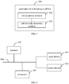
- a system for simulating the vehicle illustrated in FIG. 1 includes an upper planning module 10, a tire dynamics module 20, and a vehicle body dynamics module 30.
- the upper planning module 10 is configured to issue a control instruction to the tire dynamics module 20 and the vehicle body dynamics module 30 based on a simulation requirement.
- the tire dynamics module 20 and the vehicle body dynamics module 30 are configured to determine motion data of a vehicle body based on the control instruction according to a pre-constructed tire model and a pre-constructed vehicle body model, and to feed the motion data of the vehicle body back to the upper planning module 10.
- the upper planning module 10 is also configured to control the vehicle in a virtual simulation platform to perform simulation operation of the vehicle based on the motion data of the vehicle body.
- FIG. 1B is a flow chart illustrating a method for simulating a vehicle according to Embodiment one of the disclosure.
- Embodiments of the disclosure are applicable to a condition where an unmanned vehicle is simulated and tested.
- the method is executed by an apparatus for simulating a vehicle.
- the apparatus is implemented by software and/or hardware, and is specifically configured in an electronic device.
- the electronic device may be integrated into a control system of the vehicle.
- the method for simulating the vehicle illustrated in FIG. 1B includes the following.
- a tire translational force at a current moment is determined by a tire dynamics module based on a control instruction issued by an upper planning module and motion data of a vehicle body and a tire normal load outputted by a vehicle body dynamics module at a previous moment.
- the control instruction includes at least one of: a gear position, a driving pedal opening, a braking pedal opening, and a steering angle of a steering wheel, which is configured to simulate a condition where control is performed on a vehicle while a driver drives the vehicle.
- the tire translational force includes a tire lateral force and a tire longitudinal force.
- the tire lateral force is used to influence a driving direction of the vehicle, and may be controlled by issuing a control instruction including the steering angle of the steering wheel.
- the tire longitudinal force may affect a running speed of the vehicle, and perform vehicle acceleration and deceleration control by issuing a control instruction including the gear, the driving pedal opening and the braking pedal opening.
- a longitudinal direction is a horizontal forward direction along a rotation direction of the tire
- a lateral direction is a direction where a surface of the tire points to the left and is perpendicular to the longitudinal direction.
- a front wheel and a rear wheel correspond to different lateral directions and different longitudinal directions when the vehicle turns. Therefore, the tire normal load and the tire translational force need to be calculated separately for the front wheel and the rear wheel.
- motion data of the vehicle body and a tire normal load at the current moment are determined by the vehicle body dynamics module based on the control instruction and the tire translational force at the current moment.
- the motion data of the vehicle body at the current moment is used for vehicle simulation, and the tire normal load at the current moment is used to determine a tire translational force at a next moment.
- the motion data of the vehicle body includes at least one of: an acceleration of the vehicle body, a velocity of the vehicle body, a position of the vehicle body, a yaw angle of the vehicle body, and the like
- the tire normal load represents a force of the tire in a vertical direction.
- the vehicle body dynamics module determines the motion data of the vehicle body and the tire normal load at the current moment based on the control instruction and the tire translational force at the current moment outputted by the tire dynamics module.
- the vehicle body dynamics module also sends the motion data of the vehicle body at the current moment to the upper planning module after determining the tire normal load and the motion data of the vehicle body at the current moment, thereby enabling the upper planning module performing the vehicle simulation based on the motion data of the vehicle body at the current moment.
- a coordinate system employed by the vehicle body dynamics module is different from a coordinate system employed by the upper planning module.
- the motion data of the vehicle body at the current moment is transformed through the vehicle body dynamics module from a first coordinate system employed by the vehicle body dynamics module into a second coordinate system employed by the upper planning module before the motion data of the vehicle body at the current moment is sent by the vehicle body dynamics module to the upper planning module.
- the first coordinate system may be a vehicle body coordinate system
- the second coordinate system may be a world coordinate system
- a center of mass of the vehicle is taken as an origin
- a direction which the head of the vehicle points to is taken as an x axis direction
- a direction vertical to the left of the head of the vehicle is taken as a y axis direction
- the vertical direction passing through the center of mass of the vehicle is taken as a z axis direction.
- the method in order to determine the tire translational force at the next moment, after determining the motion data of the vehicle body and the tire normal load at the current moment, the method also includes: sending, by the vehicle body dynamics module, the tire normal load at the current moment to the tire dynamics module; and determining, by the tire dynamics module, the tire translational force at the next moment based on the tire normal load at the current moment.
- the control instruction is merely used to represent a simulation quantity of a module (such as a throttle, a brake, a gear or a steering wheel) operated in the vehicle. Therefore, the control instruction needs to be converted into data which may be recognized by the tire dynamics module and the vehicle body dynamics module.
- control instruction may also be converted into a vehicle control parameter based on a preset calibration table of control parameters through a preprocessing module while the upper planning module issues the control instruction to the tire dynamics module and the vehicle body dynamics module.
- vehicle control parameter includes driving torque and/or braking torque.
- the preprocessing module sends the vehicle control parameter to the tire dynamics module and the vehicle body dynamics module for using.
- the preprocessing module may also be incorporated into the tire dynamics module and/or the vehicle body dynamics module, such that the control instruction may be converted into the vehicle control parameter based on the preset calibration table of control parameters through the tire dynamics module and/or the vehicle body dynamics module.
- the tire dynamics module or the vehicle body dynamics module is configured to convert the control instruction, the converted vehicle control parameter is transmitted to another dynamics module for using.
- the tire translational force at the current moment is determined by the tire dynamics module based on the control instruction issued by the upper planning module and the motion data of the vehicle body and the tire normal load outputted by the vehicle body dynamics module at the previous moment.
- the motion data of the vehicle body and the tire normal load at the current moment are determined by the vehicle body dynamics module based on the control instruction and the tire translational force at the current moment.
- the motion data of the vehicle body at the current moment is used for vehicle simulation, and the tire normal load at the current moment is used to determine the tire translational force at the next moment.
- the control instruction issued by the upper planning module is processed by the tire dynamics module and the vehicle body dynamics module, data interaction is performed between the tire dynamics module and the vehicle body dynamics module, and then the tire translational force, the motion data of the vehicle body and the tire normal load are determined.
- the combination of the dynamic model and an existing integrated framework of the unmanned vehicle is realized.
- a complete closed loop is formed for a simulation test of the vehicle.
- the accuracy of a result of the simulation test of the vehicle is improved, and a matching degree between the result of the simulation test and a result of a road test is further improved.
- the simulation test may replace the road test when a new vehicle feature is introduced into the unmanned vehicle, thereby improving the test efficiency of the vehicle and reducing the test cost of the vehicle.
- the vehicle body dynamics module and the tire dynamics module are configured to determine the tire translational force, the motion data of the vehicle body and the tire normal load respectively.
- Different dynamics modules perform operations respectively and complement each other at the same time, thereby implementing the decoupling between code segments in the dynamic model.
- FIG. 2B is a schematic diagram illustrating a vehicle body model in a horizontal direction according to Embodiment two of the disclosure. This embodiment of the disclosure is further optimized and improved on the basis of the technical solution of the above embodiments.
- the operation determining the tire translational force at the current moment based on the control instruction and the motion data of the vehicle body and the tire normal load outputted by the vehicle body dynamics module at the previous moment
- the operation “converting, by the tire dynamics module and/or the vehicle body dynamics module, the control instruction into a vehicle control parameter based on a preset calibration table of control parameters, the vehicle control parameter comprising driving torque and/or braking torque” is performed, which provides data support for subsequently determining the motion data of the vehicle body at the current moment.
- the degree of freedom is used to represent the number of independent coordinates.
- a lateral translation of the vehicle, a longitudinal translation of the vehicle, and a rotation of the vehicle around the z axis provide three degrees of freedom.
- Embodiments of the disclosure involve three coordinate systems, which are respectively a tire coordinate system, a vehicle body coordinate system, and a world coordinate system.
- the tire dynamics module performs data computation based on the tire coordinate system.
- the tire coordinate system of the front wheel is represented by O f x f y f z f , where, Of represents the center of the front wheel; x f represents a direction which the front wheel rotates horizontally forward; y f represents a direction which the left of the surface of the front wheel points to and is perpendicular to x f ; and z f represents a direction which follows the right-hand rule and goes up vertically.
- the tire coordinate system of the rear wheel is represented by O r x r y r z r , where, Or represents the center of the rear wheel; x r represents a direction which the rear wheel rotates horizontally forward; y r represents a direction which the left of the surface of the rear wheel points to and is perpendicular to x r ; and z r represents a direction which follows the right-hand rule and goes up vertically.
- the vehicle body dynamics module performs data computation based on the vehicle body coordinate system.
- the vehicle body coordinate system is represented by Oxyz, where O represents a center of mass of the vehicle; a direction which the head of the vehicle points to is the x-axis direction; a direction vertical to the left side of the head of the vehicle is taken as the y axis direction; and a vertical direction is taken as the z-axis direction.
- the method illustrated in FIG. 2B includes the following.
- control instruction is converted into the vehicle control parameter by the tire dynamics module and/or the vehicle body dynamics module based on the preset calibration table of control parameters.
- the vehicle control parameter includes the driving torque and/or the braking torque.
- the tire dynamics module determines the tire translational force first, and then the vehicle body dynamics module determines the motion data of the vehicle body based on the tire translational force determined by the tire dynamics module. Therefore, in order to reduce the amount of data interaction between the upper planning module and the two dynamics modules, the tire dynamics module generally converts the control instruction into the vehicle control parameter, and the vehicle body dynamics module obtains data from the tire dynamics module when needing the data.
- the tire translational force at the current moment is determined by the tire dynamics module based on the control instruction issued by the upper planning module and the motion data of the vehicle body and the tire normal load outputted by the vehicle body dynamics module at the previous moment.
- the tire dynamics module determines the tire translational force at the current moment based on a tire model.
- the tire coordinate system is used in the tire model.
- determining the tire translational force at the current moment based on the control instruction, the motion data of the vehicle body and the tire normal load outputted by the vehicle body dynamics module at the previous moment may include: determining a tire motion parameter at the current moment based on the driving torque, the braking torque, a tire rotation radius, a tire pressure, and a velocity of the vehicle body and the tire normal load outputted by the vehicle body dynamics module at the previous moment; determining a tire longitudinal sliding rate at the current moment based on the tire rotation radius, the tire motion parameter and the velocity of the vehicle body outputted by the vehicle body dynamics module at the previous moment, and determining a tire longitudinal force at the current moment based on the tire longitudinal sliding rate and the tire normal load outputted by the vehicle body dynamics module at the previous moment; and determining a tire lateral slip angle at the current moment based on a tire wheelbase, the tire motion parameter and the vehicle body velocity outputted by the vehicle body dynamics module at the previous moment, and determining a tire lateral force at the current moment based on the tire lateral
- the tire motion parameter may be a tire rotational acceleration or a tire rotational velocity.
- the tire rotation acceleration includes a rotation acceleration ⁇ f of the front wheel and a rotation acceleration ⁇ r of the rear wheel.
- the tire rotational velocity includes a rotation velocity ⁇ f of the front wheel and a rotation velocity ⁇ r of the rear wheel.
- T af represents a driving torque of the front wheel
- T ar represents a driving torque of the rear wheel
- T bf represents a braking torque of the front wheel
- T b r represents a braking torque of the rear wheel
- R e represents the tire rotation radius
- p i represents the tire pressure
- F zf represents a tire normal load of the front wheel
- F zr represents a tire normal load of the rear wheel, which are respectively outputted by the vehicle body dynamics module at the previous moment.
- a, b, c, ⁇ , and ⁇ are constants.
- M yf represents a rolling friction torque of the front wheel
- M yr represents a rolling friction torque of the rear wheel.
- ⁇ f ( t -1) represents a rotational speed of the front wheel at the previous moment
- ⁇ r ( t -1) represents a rotational speed of the rear wheel at the previous moment
- F xf represents a longitudinal force of the front wheel
- F xr represents a longitudinal force of the rear wheel, which are included in tire longitudinal force F x at the previous moment.
- v 0.01
- b 0
- c 0
- ⁇ 0
- ⁇ 1.
- T af and T ar may assign the driving torques based on a vehicle driving mode
- T bf and T br may assign the braking torques based on a vehicle braking mode
- the tire longitudinal sliding rate includes a longitudinal sliding rate ⁇ f of the front wheel, and a longitudinal sliding rate ⁇ r of the rear wheel.
- the tire longitudinal force includes a longitudinal force F xf of the front wheel, and a longitudinal force F xr of the rear wheel.
- the tire lateral slip angle includes a lateral slip angle ⁇ f of the front wheel, and a lateral slip angle ⁇ r of the rear wheel.
- the tire lateral force includes a lateral force F yj of the front wheel and a lateral force F yr of the rear wheel.
- the motion data of the vehicle body and the tire normal load at the current moment are determined by the vehicle body dynamics module based on the control instruction and the tire translational force at the current moment.
- the motion data of the vehicle body at the current moment is used for vehicle simulation, and the tire normal load at the current moment is used to determine a tire translational force at a next moment.
- determining the motion data of the vehicle body and the tire normal load at the current moment based on the control instruction and the tire translational force at the current moment may include: determining an air resistance and an air resistance torque based on a wind speed and a tire wheelbase; determining an acceleration of the vehicle body and a yaw angle acceleration of the vehicle body based on a vehicle rotating inertia, the air resistance, the air resistance torque and the tire translational force at the current moment outputted by the tire dynamics module; determining the tire normal load based on the acceleration of the vehicle body, the yaw angle acceleration of the vehicle body, the tire wheelbase, the air resistance and the air resistance torque at the current moment; and determining a motion parameter of the vehicle body based on the acceleration of the vehicle body and the yaw angle acceleration of the vehicle body.
- the motion parameter of the vehicle body includes at least one of: the acceleration of the vehicle body, the velocity of the vehicle body, a position of the vehicle body, a yaw angle of the vehicle body, a yaw angle velocity of the vehicle body, and the yaw angle acceleration of the vehicle body.
- the vehicle body dynamics module performs data computation based on the vehicle body coordinate system
- the tire dynamics module performs data operation based on the tire coordinate system. Therefore, coordinate transformation needs to be performed on the tire translational force outputted by the tire dynamics module at the current moment, i.e., the longitudinal force F xf of the front wheel, the longitudinal force F xr of the rear wheel, the lateral force F yf of the front wheel and the lateral force F yr of the rear wheel.
- the air resistance torque includes an air resistance pitching moment M dp rotating along the x axis and an air resistance yaw moment M dy rotating along the y axis in the vehicle body coordinate system.
- C pm represents a torque resistance parameter of the air resistance rotating around the y axis in the vehicle body coordinate
- the tire normal load includes a normal load F zf of the front wheel and a normal load F zr of the rear wheel.
- the control instruction is converted into the vehicle control parameter based on the preset calibration table of control parameters by the tire dynamics module and/or the vehicle body dynamics module.
- simulation data that may be recognized by the vehicle may be converted into the data that may be used by the tire dynamics module and the vehicle body dynamics module, thereby providing data support for the tire dynamics module and the vehicle body dynamics module to determine the final motion data of the vehicle body.
- FIG. 3 is a block diagram illustrating an apparatus for simulating a vehicle according to Embodiment three of the disclosure.
- Embodiments of the disclosure are applicable to a condition where an unmanned vehicle is simulated and tested.
- the apparatus is implemented by software and/or hardware, and is specifically configured in an electronic device.
- the electronic device may be integrated into a control system of the vehicle.
- the apparatus 300 for simulating the vehicle illustrated in FIG. 3 includes a tire dynamics module 301 and a vehicle body dynamics module 302.
- the tire dynamics module 301 is configured to determine a tire translational force at a current moment based on a control instruction issued by an upper planning module and motion data of a vehicle body and a tire normal load outputted by the vehicle body dynamics module 302 at a previous moment.
- the vehicle body dynamics module 302 is configured to determine motion data of the vehicle body and a tire normal load at the current moment based on the control instruction and the tire translational force at the current moment.
- the motion data of the vehicle body at the current moment is used for vehicle simulation.
- the tire normal load at the current moment is used to determine a tire translational force at a next moment.
- the tire translational force at the current moment is determined by the tire dynamics module based on the control instruction issued by the upper planning module and the motion data of the vehicle body and the tire normal load outputted by the vehicle body dynamics module at the previous moment.
- the motion data of the vehicle body and the tire normal load at the current moment are determined by the vehicle body dynamics module based on the control instruction and the tire translational force at the current moment.
- the motion data of the vehicle body at the current moment is used for vehicle simulation, and the tire normal load at the current moment is used to determine the tire translational force at the next moment.
- the control instruction issued by the upper planning module is processed by the tire dynamics module and the vehicle body dynamics module, data interaction is performed between the tire dynamics module and the vehicle body dynamics module, and then the tire translational force, the motion data of the vehicle body and the tire normal load are determined.
- a complete closed loop is formed for a simulation test of the vehicle.
- the accuracy of a result of the simulation test of the vehicle is improved, and a matching degree between the result of the simulation test and a result of a road test is further improved.
- the simulation test may replace the road test when a new vehicle feature is introduced into the unmanned vehicle, thereby improving the test efficiency of the vehicle and reducing the test cost of the vehicle.
- the vehicle body dynamics module and the tire dynamics module are configured to determine the tire translational force, the motion data of the vehicle body and the tire normal load respectively, thereby implementing the decoupling between code segments in the dynamic model.
- the vehicle body dynamics module is also configured to send the motion data of the vehicle body at the current moment to the upper planning module, to enable the upper planning module performing the vehicle simulation based on the motion data of the vehicle body at the current moment.
- the vehicle body dynamics module is also configured to send the tire normal load at the current moment to the tire dynamics module; and the tire dynamics module is also configured to determine the tire translational force at the next moment based on the tire normal load at the current moment.
- control instruction includes at least one of: a gear position, a driving pedal opening, a braking pedal opening, and a steering angle of a steering wheel.
- the tire dynamics module 301 and/or the vehicle body dynamics module 302 is also configured to convert the control instruction into a vehicle control parameter based on a preset calibration table of control parameters.
- the vehicle control parameter includes driving torque and/or braking torque.
- the tire dynamics module 301 is configured to determine a tire motion parameter at the current moment based on the driving torque, the braking torque, a tire rotation radius, a tire pressure, and a velocity of the vehicle body and the tire normal load outputted by the vehicle body dynamics module at the previous moment; to determine a tire longitudinal sliding rate at the current moment based on the tire rotation radius, the tire motion parameter and the velocity of the vehicle body outputted by the vehicle body dynamics module at the previous moment, and determining a tire longitudinal force at the current moment based on the tire longitudinal sliding rate and the tire normal load outputted by the vehicle body dynamics module at the previous moment; and to determine a tire lateral slip angle at the current moment based on a tire wheelbase, the tire motion parameter and the vehicle body velocity outputted by the vehicle body dynamics module at the previous moment, and determining a tire lateral
- the tire translational force includes the tire longitudinal force and the tire lateral force.
- the vehicle body dynamics module 302 is also configured to determine an air resistance and an air resistance torque based on a wind speed and a tire wheelbase; to determine an acceleration of the vehicle body and a yaw angle acceleration of the vehicle body based on a vehicle rotating inertia, the air resistance, the air resistance torque and the tire translational force at the current moment outputted by the tire dynamics module; to determine the tire normal load based on the acceleration of the vehicle body, the yaw angle acceleration of the vehicle body, the tire wheelbase, the air resistance and the air resistance torque at the current moment; and to determine a motion parameter of the vehicle body based on the acceleration of the vehicle body and the yaw angle acceleration of the vehicle body.
- the motion parameter of the vehicle body includes at least one of: the acceleration of the vehicle body, the velocity of the vehicle body, a position of the vehicle body, a yaw angle of the vehicle body, a yaw angle velocity of the vehicle body, and the yaw angle acceleration of the vehicle body.
- vehicle body dynamics module 302 is also configured to transform the motion data of the vehicle body at the current moment from a first coordinate system employed by the vehicle body dynamics module to a second coordinate system employed by the upper planning module before sending the motion data of the vehicle body at the current moment to the upper planning module.
- the above apparatus for simulating the vehicle may execute the method for simulating the vehicle according to any of embodiments of the disclosure, and has corresponding functional modules for executing the method for simulating the vehicle and beneficial effects corresponding to the method.
- the disclosure also provides an electronic device and a readable storage medium.
- FIG 4 is a block diagram illustrating an electronic device capable of implementing a method for simulating a vehicle according to embodiments of the disclosure.
- the electronic device aims to represent various forms of digital computers, such as a laptop computer, a desktop computer, a workstation, a personal digital assistant, a server, a blade server, a mainframe computer and other suitable computer.
- the electronic device may also represent various forms of mobile devices, such as personal digital processing, a cellular phone, a smart phone, a wearable device and other similar computing device.
- the components, connections and relationships of the components, and functions of the components illustrated herein are merely examples, and are not intended to limit the implementation of the disclosure described and/or claimed herein.
- the electronic device includes: one or more processors 401, a memory 402, and interfaces for connecting various components, including a high-speed interface and a low-speed interface.
- Various components are connected to each other via different buses, and may be mounted on a common main board or in other ways as required.
- the processor may process instructions executed within the electronic device, including instructions stored in or on the memory to display graphical information of the GUI (graphical user interface) on an external input/output device (such as a display device coupled to an interface).
- multiple processors and/or multiple buses may be used together with multiple memories if desired.
- multiple electronic devices may be connected, and each device provides some necessary operations (for example, as a server array, a group of blade servers, or a multiprocessor system).
- a processor 401 is taken as an example.
- the memory 402 is a non-transitory computer readable storage medium provided by the disclosure.
- the memory is configured to store instructions executable by at least one processor, to enable the at least one processor to execute the method for simulating the vehicle provided by the disclosure.
- the non-transitory computer readable storage medium provided by the disclosure is configured to store computer instructions.
- the computer instructions are configured to enable a computer to execute the method for simulating the vehicle provided by the disclosure.
- the memory 402 may be configured to store non-transitory software programs, non-transitory computer executable programs and modules, such as program instructions/module (such as the tire dynamics module 301 and the vehicle body dynamics module 302 illustrated in FIG. 3 ) corresponding to the method for simulating the vehicle according to embodiments of the disclosure.
- the processor 401 is configured to execute various functional applications and data processing of the server by operating non-transitory software programs, instructions and modules stored in the memory 402, that is, implements the method for simulating the vehicle according to the above method embodiments.
- the memory 402 may include a storage program region and a storage data region.
- the storage program region may store an application required by an operating system and at least one function.
- the storage data region may store data created according to predicted usage of the electronic device based on the semantic representation.
- the memory 402 may include a high-speed random access memory, and may also include a non-transitory memory, such as at least one disk memory device, a flash memory device, or other non-transitory solid-state memory device.
- the memory 402 may optionally include memories remotely located to the processor 401, and these remote memories may be connected to the electronic device via a network. Examples of the above network include, but are not limited to, an Internet, an intranet, a local area network, a mobile communication network and combinations thereof.
- the electronic device capable of implementing the method for detecting the mobile traffic light may also include: an input device 403 and an output device 404.
- the processor 401, the memory 402, the input device 403, and the output device 404 may be connected via a bus or in other means. In FIG. 4 , the bus is taken as an example.
- the input device 403 may receive inputted digital or character information, and generate key signal input related to user setting and function control of the electronic device capable of implementing the method for detecting the mobile traffic light, such as a touch screen, a keypad, a mouse, a track pad, a touch pad, an indicator stick, one or more mouse buttons, a trackball, a joystick and other input device.
- the output device 404 may include a display device, an auxiliary lighting device (e.g., LED), a haptic feedback device (e.g., a vibration motor), and the like.
- the display device may include, but be not limited to, a liquid crystal display (LCD), a light emitting diode (LED) display, and a plasma display. In some embodiments, the display device may be the touch screen.
- the various implementations of the system and technologies described herein may be implemented in a digital electronic circuit system, an integrated circuit system, an application specific ASIC (application specific integrated circuit), a computer hardware, a firmware, a software, and/or combinations thereof. These various implementations may include: being implemented in one or more computer programs.
- the one or more computer programs may be executed and/or interpreted on a programmable system including at least one programmable processor.
- the programmable processor may be a special purpose or general purpose programmable processor, may receive data and instructions from a storage system, at least one input device, and at least one output device, and may transmit data and the instructions to the storage system, the at least one input device, and the at least one output device.
- machine readable medium and “computer readable medium” refer to any computer program product, device, and/or apparatus (such as, a magnetic disk, an optical disk, a memory, a programmable logic device (PLD)) for providing machine instructions and/or data to a programmable processor, including a machine readable medium that receives machine instructions as a machine readable signal.
- machine readable signal refers to any signal for providing the machine instructions and/or data to the programmable processor.
- the system and technologies described herein may be implemented on a computer.
- the computer has a display device (such as, a CRT (cathode ray tube) or a LCD (liquid crystal display) monitor) for displaying information to the user, a keyboard and a pointing device (such as, a mouse or a trackball), through which the user may provide the input to the computer.
- a display device such as, a CRT (cathode ray tube) or a LCD (liquid crystal display) monitor
- a keyboard and a pointing device such as, a mouse or a trackball
- Other types of devices may also be configured to provide interaction with the user.
- the feedback provided to the user may be any form of sensory feedback (such as, visual feedback, auditory feedback, or tactile feedback), and the input from the user may be received in any form (including acoustic input, voice input or tactile input).
- the system and technologies described herein may be implemented in a computing system including a background component (such as, a data server), a computing system including a middleware component (such as, an application server), or a computing system including a front-end component (such as, a user computer having a graphical user interface or a web browser through which the user may interact with embodiments of the system and technologies described herein), or a computing system including any combination of such background component, the middleware components and the front-end component.
- Components of the system may be connected to each other via digital data communication in any form or medium (such as, a communication network). Examples of the communication network include a local area network (LAN), a wide area networks (WAN), and the Internet.
- the computer system may include a client and a server.
- the client and the server are generally remote from each other and generally interact via the communication network.
- a relationship between the client and the server is generated by computer programs operated on a corresponding computer and having a client-server relationship with each other.
- the tire translational force at the current moment is determined by the tire dynamics module based on the control instruction issued by the upper planning module and the motion data of the vehicle body and the tire normal load outputted by the vehicle body dynamics module at the previous moment.
- the motion data of the vehicle body and the tire normal load at the current moment are determined by the vehicle body dynamics module based on the control instruction and the tire translational force at the current moment.
- the motion data of the vehicle body at the current moment is used for vehicle simulation, and the tire normal load at the current moment is used to determine the tire translational force at the next moment.
- the control instruction issued by the upper planning module is processed by the tire dynamics module and the vehicle body dynamics module, data interaction is performed between the tire dynamics module and the vehicle body dynamics module, and then the tire translational force, the motion data of the vehicle body and the tire normal load are determined.
- the combination of the dynamic model and an existing integrated framework of the unmanned vehicle is realized.
- a complete closed loop is formed for a simulation test of the vehicle.
- the accuracy of a result of the simulation test of the vehicle is improved, and a matching degree between the result of the simulation test and a result of a road test is further improved.
- the simulation test may replace the road test when a new vehicle feature is introduced into the unmanned vehicle, thereby improving the test efficiency of the vehicle and reducing the test cost of the vehicle.
- the vehicle body dynamics module and the tire dynamics module are configured to determine the tire translational force, the motion data of the vehicle body and the tire normal load respectively.
- Different dynamics modules perform operations respectively and complement each other at the same time, thereby implementing the decoupling between code segments in the dynamic model.
Abstract
Description
- The disclosure relates to a field of data processing technologies and particularly to a field of automatic driving technologies, and particularly relates to a method and an apparatus for simulating a vehicle, a device, and a medium.
- An unmanned vehicle is a kind of intelligent vehicles, also referred as a wheeled mobile robot. The unmanned vehicle senses road environment through an on-board sensing system, automatically plans a driving route, and is controlled to reach a predetermined destination.
- With the advancement of technologies, a performance of the unmanned vehicle is constantly optimized. The performance of the unmanned vehicle generally needs to be tested when a new vehicle feature is applied to the unmanned vehicle. The test includes a simulation test and a road test.
- In the related art, when simulation is performed on the unmanned vehicle, the simulation is mainly realized by directly issuing vehicle status information such as planning speed information and location information, without considering an actual implementation of the unmanned vehicle. Therefore, there is a large difference between a simulation effect and an actual operation result of the unmanned vehicle, thereby causing a higher time cost and a higher economic cost of a vehicle test.
- Embodiments of the disclosure provide a method and an apparatus for simulating a vehicle, a device, and a medium, to improve a matching degree between a simulation test and a road test, further implementing a substitution of the simulation test for the road test, improving a test efficiency of the vehicle, and reducing a test cost.
- In a first aspect, embodiments of the disclosure provide a method for simulating a vehicle. The method includes: determining, by a tire dynamics module, a tire translational force at a current moment based on a control instruction issued by an upper planning module and motion data of a vehicle body and a tire normal load outputted by a vehicle body dynamics module at a previous moment; and determining, by the vehicle body dynamics module, motion data of the vehicle body and a tire normal load at the current moment based on the control instruction and the tire translational force at the current moment, the motion data of the vehicle body at the current moment being used for vehicle simulation, and the tire normal load at the current moment being used to determine a tire translational force at a next moment.
- With embodiments of the disclosure, the tire translational force at the current moment is determined by the tire dynamics module based on the control instruction issued by the upper planning module, and the motion data of the vehicle body and the tire normal load outputted by the vehicle body dynamics module at the previous moment. The motion data of the vehicle body and the tire normal load at the current moment are determined by the vehicle body dynamics module based on the control instruction and the tire translational force at the current moment. The motion data of the vehicle body at the current moment is used for vehicle simulation, and the tire normal load at the current moment is used to determine the tire translational force at the next moment. With the above technical solution, the control instruction issued by the upper planning module is processed by the tire dynamics module and the vehicle body dynamics module, data interaction is performed between the tire dynamics module and the vehicle body dynamics module, and then the tire translational force, the motion data of the vehicle body and the tire normal load are determined. In this way, a combination of a dynamic model and an existing integrated framework of the unmanned vehicle is realized. A complete closed loop is formed for the simulation test of the vehicle. The accuracy of a result of the simulation test of the vehicle is improved, and the matching degree between the result of the simulation test and a result of the road test is further improved. The simulation test may replace the road test when a new vehicle feature is introduced into the unmanned vehicle, thereby improving the test efficiency of the vehicle and reducing the test cost of the vehicle. Meanwhile, the vehicle body dynamics module and the tire dynamics module are respectively configured to determine the tire translational force, the motion data of the vehicle body and the tire normal load. Different dynamics modules perform operations respectively and complement each other at the same time, thereby implementing the decoupling between code segments in the dynamic model.
- Alternatively, after determining the motion data of the vehicle body and the tire normal load at the current moment, the method also includes: sending, by the vehicle body dynamics module, the motion data of the vehicle body at the current moment to the upper planning module, to enable the upper planning module performing the vehicle simulation based on the motion data of the vehicle body at the current moment.
- With the alternative implementation of the disclosure, after the motion data of the vehicle body and the tire normal load at the current moment are determined, the motion data of the vehicle body at the current moment is sent by the vehicle body dynamics module to the upper planning module, to enable the upper planning module performing the vehicle simulation based on the motion data of the vehicle body at the current moment, thereby implementing to control the vehicle simulation procedure.
- Alternatively, after determining the motion data of the vehicle body and the tire normal load at the current moment, the method also includes: sending, by the vehicle body dynamics module, the tire normal load at the current moment to the tire dynamics module; and determining, by the tire dynamics module, the tire translational force at the next moment based on the tire normal load at the current moment.
- With the alternative implementation of the disclosure, after the motion data of the vehicle body and the tire normal load at the current moment are determined, the tire normal load at the current moment is sent by the vehicle body dynamics module to the tire dynamics module, and the tire translational force at the next moment is determined by the tire dynamics module based on the tire normal load at the current moment, thereby providing data support for performing the vehicle simulation at the next moment.
- Alternatively, the control instruction includes at least one of: a gear position, a driving pedal opening, a braking pedal opening, and a steering angle of a steering wheel.
- With the alternative implementation of the disclosure, by performing refinement on the control instruction, an application scene for the simulation test of the vehicle is enriched, such that the simulation test of the vehicle may be realized in conditions of increasing and decreasing the gear, increasing and decreasing an accelerator, braking and steering.
- Alternatively, before determining the tire translational force at the current moment based on the control instruction and the motion data of the vehicle body and the tire normal load outputted by the vehicle body dynamics module at the previous moment, the method also includes: converting, by the tire dynamics module and/or the vehicle body dynamics module, the control instruction into a vehicle control parameter based on a preset calibration table of control parameters, the vehicle control parameter including driving torque and/or braking torque.
- With the alternative implementation of the disclosure, before the tire translational force is determined, the control instruction is converted into a vehicle control parameter based on the preset calibration table of control parameters by the tire dynamics module and/or the vehicle body dynamics module, thereby providing guarantee for subsequently determining of the motion data of the vehicle body, the tire translational force and the tire normal load.
- Alternatively, determining the tire translational force at the current moment based on the control instruction issued by the upper planning module and the motion data of the vehicle body and the tire normal load outputted by the vehicle body dynamics module at the previous moment includes: determining a tire motion parameter at the current moment based on the driving torque, the braking torque, a tire rotation radius, a tire pressure, and a velocity of the vehicle body and the tire normal load outputted by the vehicle body dynamics module at the previous moment; determining a tire longitudinal sliding rate at the current moment based on the tire rotation radius, the tire motion parameter and the velocity of the vehicle body outputted by the vehicle body dynamics module at the previous moment, and determining a tire longitudinal force at the current moment based on the tire longitudinal sliding rate and the tire normal load outputted by the vehicle body dynamics module at the previous moment; and determining a tire lateral slip angle at the current moment based on a tire wheelbase, the tire motion parameter and the vehicle body velocity outputted by the vehicle body dynamics module at the previous moment, and determining a tire lateral force at the current moment based on the tire lateral slip angle and the tire normal load outputted by the vehicle body dynamics module at the previous moment,
- The tire translational force includes the tire longitudinal force and the tire lateral force.
- With the alternative implementation of the disclosure, the determination of the tire translational force at the current moment is refined into the determination of the tire motion parameter, and the tire longitudinal force and the tire lateral force are respectively determined based on the tire motion parameter, thereby improving a determination mechanism of the tire translational force.
- Alternatively, determining the motion data of the vehicle body and the tire normal load at the current moment based on the control instruction and the tire translational force at the current moment includes: determining an air resistance and an air resistance torque based on a wind speed and a tire wheelbase; determining an acceleration of the vehicle body and a yaw angle acceleration of the vehicle body based on a vehicle rotating inertia, the air resistance, the air resistance torque and the tire translational force at the current moment outputted by the tire dynamics module; determining the tire normal load based on the acceleration of the vehicle body, the yaw angle acceleration of the vehicle body, the tire wheelbase, the air resistance and the air resistance torque at the current moment; and determining a motion parameter of the vehicle body based on the acceleration of the vehicle body and the yaw angle acceleration of the vehicle body.
- The motion parameter of the vehicle body includes at least one of: the acceleration of the vehicle body, the velocity of the vehicle body, a position of the vehicle body, a yaw angle of the vehicle body, a yaw angle velocity of the vehicle body, and the yaw angle acceleration of the vehicle body.
- With the alternative implementation of the disclosure, the operation "determining the motion data of the vehicle body and the tire normal load at the current moment" is refined as the operations "determining the air resistance and the air resistance torque" and "determining an acceleration of the vehicle body and a yaw angle acceleration of the vehicle body", thereby determining the motion parameter of the vehicle body and the tire normal load at the current moment based on the above determination results, and improving the determination mechanism of the motion parameter of the vehicle body and the tire normal load at the current moment.
- Alternatively, before sending, by the vehicle body dynamics module, the motion data of the vehicle body at the current moment to the upper planning module, the method also includes: transforming, by the vehicle body dynamics module, the motion data of the vehicle body at the current moment from a first coordinate system employed by the vehicle body dynamics module to a second coordinate system employed by the upper planning module.
- With the alternative implementation of the disclosure, before the motion data of the vehicle body at the current moment is sent to the upper planning module by the vehicle body dynamics module, coordinate system transformation is performed on the motion data of the vehicle body at the current moment, thereby enable the upper planning module directly performing the vehicle simulation based on the motion data of the vehicle body, reducing the amount of data calculation of the upper planning module, and implementing the control transparency of the upper planning module and the direct reuse of the existing upper planning module.
- In a second aspect, embodiments of the disclosure also provide an apparatus for simulating a vehicle. The apparatus includes: a tire dynamics module and a vehicle body dynamics module. The tire dynamics module is configured to determine a tire translational force at a current moment based on a control instruction issued by an upper planning module and motion data of a vehicle body and a tire normal load outputted by the vehicle body dynamics module at a previous moment. The vehicle body dynamics module is configured to determine motion data of the vehicle body and a tire normal load at the current moment based on the control instruction and the tire translational force at the current moment. The motion data of the vehicle body at the current moment is used for vehicle simulation. The tire normal load at the current moment is used to determine a tire translational force at a next moment.
- In a third aspect, embodiments of the disclosure also provide an electronic device. The electronic device includes at least one processor and a memory. The memory is communicatively coupled to the at least one processor. The memory is configured to store instructions executable by the at least one processor. The at least one processor is caused to execute the method for simulating the vehicle according to the first aspect of embodiments when the instructions are executed by the at least one processor.
- In a fourth aspect, embodiments of the disclosure also provide a non-transitory computer readable storage medium having computer instructions stored thereon. The computer instructions are configured to cause a computer to execute the method for simulating the vehicle according to the first aspect of embodiments.
- Other effects of the above alternative modes will be explained in the following with specific embodiments.
- The accompanying drawings are used for better understanding the solution and do not constitute a limitation of the disclosure.
-
FIG. 1A is a block diagram illustrating a software structure of a system for simulating a vehicle according to an embodiment of the disclosure. -
FIG. 1B is a flow chart illustrating a method for simulating a vehicle according to Embodiment one of the disclosure. -
FIG. 2A is a schematic diagram illustrating a vehicle body model in a horizontal direction according to Embodiment two of the disclosure. -
FIG. 2B is a flow chart illustrating a method for simulating a vehicle according to Embodiment two of the disclosure. -
FIG. 3 is a block diagram illustrating an apparatus for simulating a vehicle according to Embodiment three of the disclosure. -
FIG. 4 is a block diagram illustrating an electronic device capable of implementing a method for simulating a vehicle according to embodiments of the disclosure. - Description will be made below to exemplary embodiments of the disclosure with reference to accompanying drawings, which includes various details of embodiments of the disclosure to facilitate understanding and should be regarded as merely examples. Therefore, it should be recognized by the skilled in the art that various changes and modifications may be made to the embodiments described herein without departing from the scope and spirit of the disclosure. Meanwhile, for clarity and conciseness, descriptions for well-known functions and structures are omitted in the following description.
- In order to clearly describe technical solutions of subsequent embodiments, exemplified description is first made to a software structure of a system for simulating a vehicle according to embodiments of the disclosure.
- A system for simulating the vehicle illustrated in
FIG. 1 includes an upper planning module 10, a tire dynamics module 20, and a vehicle body dynamics module 30. - The upper planning module 10 is configured to issue a control instruction to the tire dynamics module 20 and the vehicle body dynamics module 30 based on a simulation requirement.
- The tire dynamics module 20 and the vehicle body dynamics module 30 are configured to determine motion data of a vehicle body based on the control instruction according to a pre-constructed tire model and a pre-constructed vehicle body model, and to feed the motion data of the vehicle body back to the upper planning module 10.
- The upper planning module 10 is also configured to control the vehicle in a virtual simulation platform to perform simulation operation of the vehicle based on the motion data of the vehicle body.
-
FIG. 1B is a flow chart illustrating a method for simulating a vehicle according to Embodiment one of the disclosure. Embodiments of the disclosure are applicable to a condition where an unmanned vehicle is simulated and tested. The method is executed by an apparatus for simulating a vehicle. The apparatus is implemented by software and/or hardware, and is specifically configured in an electronic device. The electronic device may be integrated into a control system of the vehicle. - The method for simulating the vehicle illustrated in
FIG. 1B includes the following. - At block S101, a tire translational force at a current moment is determined by a tire dynamics module based on a control instruction issued by an upper planning module and motion data of a vehicle body and a tire normal load outputted by a vehicle body dynamics module at a previous moment.
- The control instruction includes at least one of: a gear position, a driving pedal opening, a braking pedal opening, and a steering angle of a steering wheel, which is configured to simulate a condition where control is performed on a vehicle while a driver drives the vehicle.
- The tire translational force includes a tire lateral force and a tire longitudinal force. The tire lateral force is used to influence a driving direction of the vehicle, and may be controlled by issuing a control instruction including the steering angle of the steering wheel. The tire longitudinal force may affect a running speed of the vehicle, and perform vehicle acceleration and deceleration control by issuing a control instruction including the gear, the driving pedal opening and the braking pedal opening.
- With a center of a tire as an origin, a longitudinal direction is a horizontal forward direction along a rotation direction of the tire, and a lateral direction is a direction where a surface of the tire points to the left and is perpendicular to the longitudinal direction.
- It may be understood that, a front wheel and a rear wheel correspond to different lateral directions and different longitudinal directions when the vehicle turns. Therefore, the tire normal load and the tire translational force need to be calculated separately for the front wheel and the rear wheel.
- At block S102, motion data of the vehicle body and a tire normal load at the current moment are determined by the vehicle body dynamics module based on the control instruction and the tire translational force at the current moment. The motion data of the vehicle body at the current moment is used for vehicle simulation, and the tire normal load at the current moment is used to determine a tire translational force at a next moment.
- The motion data of the vehicle body includes at least one of: an acceleration of the vehicle body, a velocity of the vehicle body, a position of the vehicle body, a yaw angle of the vehicle body, and the like
- The tire normal load represents a force of the tire in a vertical direction.
- Exemplarily, the vehicle body dynamics module determines the motion data of the vehicle body and the tire normal load at the current moment based on the control instruction and the tire translational force at the current moment outputted by the tire dynamics module.
- In an alternative implementation of embodiments of the disclosure, the vehicle body dynamics module also sends the motion data of the vehicle body at the current moment to the upper planning module after determining the tire normal load and the motion data of the vehicle body at the current moment, thereby enabling the upper planning module performing the vehicle simulation based on the motion data of the vehicle body at the current moment.
- Generally, a coordinate system employed by the vehicle body dynamics module is different from a coordinate system employed by the upper planning module. In order to reduce the amount of data calculation in the upper planning module, realize transparent control of the upper planning module and direct reuse of the upper planning module, the motion data of the vehicle body at the current moment is transformed through the vehicle body dynamics module from a first coordinate system employed by the vehicle body dynamics module into a second coordinate system employed by the upper planning module before the motion data of the vehicle body at the current moment is sent by the vehicle body dynamics module to the upper planning module.
- The first coordinate system may be a vehicle body coordinate system, and the second coordinate system may be a world coordinate system.
- In the vehicle body coordinate system, a center of mass of the vehicle is taken as an origin, a direction which the head of the vehicle points to is taken as an x axis direction, a direction vertical to the left of the head of the vehicle is taken as a y axis direction, and the vertical direction passing through the center of mass of the vehicle is taken as a z axis direction.
- In another alternative implementation of embodiments of the disclosure, in order to determine the tire translational force at the next moment, after determining the motion data of the vehicle body and the tire normal load at the current moment, the method also includes: sending, by the vehicle body dynamics module, the tire normal load at the current moment to the tire dynamics module; and determining, by the tire dynamics module, the tire translational force at the next moment based on the tire normal load at the current moment.
- It should be understood that, when the tire translational force is determined by the tire dynamics module, and the tire normal load and the motion data of the vehicle body are determined by the vehicle body dynamics module, a vector needs to be calculated based on a set algorithm model. However, the control instruction is merely used to represent a simulation quantity of a module (such as a throttle, a brake, a gear or a steering wheel) operated in the vehicle. Therefore, the control instruction needs to be converted into data which may be recognized by the tire dynamics module and the vehicle body dynamics module.
- To achieve the above objectives, the control instruction may also be converted into a vehicle control parameter based on a preset calibration table of control parameters through a preprocessing module while the upper planning module issues the control instruction to the tire dynamics module and the vehicle body dynamics module. The vehicle control parameter includes driving torque and/or braking torque. Correspondingly, the preprocessing module sends the vehicle control parameter to the tire dynamics module and the vehicle body dynamics module for using.
- It may be understood that, in order to reduce the number of modules in the control system, the preprocessing module may also be incorporated into the tire dynamics module and/or the vehicle body dynamics module, such that the control instruction may be converted into the vehicle control parameter based on the preset calibration table of control parameters through the tire dynamics module and/or the vehicle body dynamics module. When the tire dynamics module or the vehicle body dynamics module is configured to convert the control instruction, the converted vehicle control parameter is transmitted to another dynamics module for using.
- With embodiments of the disclosure, the tire translational force at the current moment is determined by the tire dynamics module based on the control instruction issued by the upper planning module and the motion data of the vehicle body and the tire normal load outputted by the vehicle body dynamics module at the previous moment. The motion data of the vehicle body and the tire normal load at the current moment are determined by the vehicle body dynamics module based on the control instruction and the tire translational force at the current moment. The motion data of the vehicle body at the current moment is used for vehicle simulation, and the tire normal load at the current moment is used to determine the tire translational force at the next moment. With the above technical solution, the control instruction issued by the upper planning module is processed by the tire dynamics module and the vehicle body dynamics module, data interaction is performed between the tire dynamics module and the vehicle body dynamics module, and then the tire translational force, the motion data of the vehicle body and the tire normal load are determined. In this way, the combination of the dynamic model and an existing integrated framework of the unmanned vehicle is realized. A complete closed loop is formed for a simulation test of the vehicle. The accuracy of a result of the simulation test of the vehicle is improved, and a matching degree between the result of the simulation test and a result of a road test is further improved. The simulation test may replace the road test when a new vehicle feature is introduced into the unmanned vehicle, thereby improving the test efficiency of the vehicle and reducing the test cost of the vehicle. Meanwhile, the vehicle body dynamics module and the tire dynamics module are configured to determine the tire translational force, the motion data of the vehicle body and the tire normal load respectively. Different dynamics modules perform operations respectively and complement each other at the same time, thereby implementing the decoupling between code segments in the dynamic model.
-
FIG. 2B is a schematic diagram illustrating a vehicle body model in a horizontal direction according to Embodiment two of the disclosure. This embodiment of the disclosure is further optimized and improved on the basis of the technical solution of the above embodiments. - Further, before the operation "determining the tire translational force at the current moment based on the control instruction and the motion data of the vehicle body and the tire normal load outputted by the vehicle body dynamics module at the previous moment", the operation "converting, by the tire dynamics module and/or the vehicle body dynamics module, the control instruction into a vehicle control parameter based on a preset calibration table of control parameters, the vehicle control parameter comprising driving torque and/or braking torque" is performed, which provides data support for subsequently determining the motion data of the vehicle body at the current moment.
- Description will be made in detail to embodiments of the disclosure with reference to a vehicle body model in the horizontal direction with three degrees of freedom (DOF) illustrated in
FIG. 2A . The degree of freedom is used to represent the number of independent coordinates. A lateral translation of the vehicle, a longitudinal translation of the vehicle, and a rotation of the vehicle around the z axis provide three degrees of freedom. - Embodiments of the disclosure involve three coordinate systems, which are respectively a tire coordinate system, a vehicle body coordinate system, and a world coordinate system.
- The tire dynamics module performs data computation based on the tire coordinate system. Taking a front wheel as an example, the tire coordinate system of the front wheel is represented by Ofxfyfzf, where, Of represents the center of the front wheel; xf represents a direction which the front wheel rotates horizontally forward; yf represents a direction which the left of the surface of the front wheel points to and is perpendicular to xf; and zf represents a direction which follows the right-hand rule and goes up vertically. Correspondingly, the tire coordinate system of the rear wheel is represented by Orxryrzr, where, Or represents the center of the rear wheel; xr represents a direction which the rear wheel rotates horizontally forward; yr represents a direction which the left of the surface of the rear wheel points to and is perpendicular to xr; and zr represents a direction which follows the right-hand rule and goes up vertically.
- The vehicle body dynamics module performs data computation based on the vehicle body coordinate system. The vehicle body coordinate system is represented by Oxyz, where O represents a center of mass of the vehicle; a direction which the head of the vehicle points to is the x-axis direction; a direction vertical to the left side of the head of the vehicle is taken as the y axis direction; and a vertical direction is taken as the z-axis direction.
- The method illustrated in
FIG. 2B includes the following. - At block S201, the control instruction is converted into the vehicle control parameter by the tire dynamics module and/or the vehicle body dynamics module based on the preset calibration table of control parameters.
- The vehicle control parameter includes the driving torque and/or the braking torque.
- Exemplarily, when the motion data of the vehicle body at the current moment is subsequently determined, the tire dynamics module determines the tire translational force first, and then the vehicle body dynamics module determines the motion data of the vehicle body based on the tire translational force determined by the tire dynamics module. Therefore, in order to reduce the amount of data interaction between the upper planning module and the two dynamics modules, the tire dynamics module generally converts the control instruction into the vehicle control parameter, and the vehicle body dynamics module obtains data from the tire dynamics module when needing the data.
- At block S202, the tire translational force at the current moment is determined by the tire dynamics module based on the control instruction issued by the upper planning module and the motion data of the vehicle body and the tire normal load outputted by the vehicle body dynamics module at the previous moment.
- The tire dynamics module determines the tire translational force at the current moment based on a tire model. The tire coordinate system is used in the tire model.
- Exemplarily, determining the tire translational force at the current moment based on the control instruction, the motion data of the vehicle body and the tire normal load outputted by the vehicle body dynamics module at the previous moment may include: determining a tire motion parameter at the current moment based on the driving torque, the braking torque, a tire rotation radius, a tire pressure, and a velocity of the vehicle body and the tire normal load outputted by the vehicle body dynamics module at the previous moment; determining a tire longitudinal sliding rate at the current moment based on the tire rotation radius, the tire motion parameter and the velocity of the vehicle body outputted by the vehicle body dynamics module at the previous moment, and determining a tire longitudinal force at the current moment based on the tire longitudinal sliding rate and the tire normal load outputted by the vehicle body dynamics module at the previous moment; and determining a tire lateral slip angle at the current moment based on a tire wheelbase, the tire motion parameter and the vehicle body velocity outputted by the vehicle body dynamics module at the previous moment, and determining a tire lateral force at the current moment based on the tire lateral slip angle and the tire normal load outputted by the vehicle body dynamics module at the previous moment. The tire translational force includes the tire longitudinal force and the tire lateral force.
- The tire motion parameter may be a tire rotational acceleration or a tire rotational velocity.
- Exemplarily, a velocity component Vxft of the front wheel in the xf direction, a velocity component Vyft of the front wheel in the yf direction, a velocity component Vxrt of the rear wheel in the xr direction and a velocity component Vyrt of the rear wheel in the yr direction are determined by the following formula:


- Exemplarily, the tire rotation acceleration includes a rotation acceleration ω̇f of the front wheel and a rotation acceleration ω̇r of the rear wheel. The tire rotational velocity includes a rotation velocity ωf of the front wheel and a rotation velocity ωr of the rear wheel. The tire rotational acceleration and the tire rotational velocity are determined by the following formula:


- Taf represents a driving torque of the front wheel, and Tar represents a driving torque of the rear wheel. Tbf represents a braking torque of the front wheel, and T br represents a braking torque of the rear wheel. Re represents the tire rotation radius. pi represents the tire pressure. Fzf represents a tire normal load of the front wheel, and Fzr represents a tire normal load of the rear wheel, which are respectively outputted by the vehicle body dynamics module at the previous moment. a, b, c, α, and β are constants. Myf represents a rolling friction torque of the front wheel, and Myr represents a rolling friction torque of the rear wheel. ω f(t-1) represents a rotational speed of the front wheel at the previous moment, and ω r(t-1) represents a rotational speed of the rear wheel at the previous moment. Fxf represents a longitudinal force of the front wheel, and Fxr represents a longitudinal force of the rear wheel, which are included in tire longitudinal force Fx at the previous moment.
- Exemplarily, v=0.01, b=0, c=0, α=0, and β=1.
- It should be noted that, Taf and Tar may assign the driving torques based on a vehicle driving mode, and Tbf and Tbr may assign the braking torques based on a vehicle braking mode.
- Exemplarily, the tire longitudinal sliding rate includes a longitudinal sliding rate κf of the front wheel, and a longitudinal sliding rate κr of the rear wheel. The tire longitudinal sliding rate at the current moment is determined by employing the following formula:

- Exemplarily, the tire longitudinal force includes a longitudinal force Fxf of the front wheel, and a longitudinal force Fxr of the rear wheel. The tire longitudinal force at the current moment is determined by employing the following formula:

- Exemplarily, the tire lateral slip angle includes a lateral slip angle αf of the front wheel, and a lateral slip angle αr of the rear wheel. The tire lateral slip angle at the current moment is determined by employing the following formula:

- Exemplarily, the tire lateral force includes a lateral force Fyj of the front wheel and a lateral force Fyr of the rear wheel. The tire lateral force at the current moment is determined by employing the following formula:

- At block S203, the motion data of the vehicle body and the tire normal load at the current moment are determined by the vehicle body dynamics module based on the control instruction and the tire translational force at the current moment. The motion data of the vehicle body at the current moment is used for vehicle simulation, and the tire normal load at the current moment is used to determine a tire translational force at a next moment.
- Exemplarily, determining the motion data of the vehicle body and the tire normal load at the current moment based on the control instruction and the tire translational force at the current moment may include: determining an air resistance and an air resistance torque based on a wind speed and a tire wheelbase; determining an acceleration of the vehicle body and a yaw angle acceleration of the vehicle body based on a vehicle rotating inertia, the air resistance, the air resistance torque and the tire translational force at the current moment outputted by the tire dynamics module; determining the tire normal load based on the acceleration of the vehicle body, the yaw angle acceleration of the vehicle body, the tire wheelbase, the air resistance and the air resistance torque at the current moment; and determining a motion parameter of the vehicle body based on the acceleration of the vehicle body and the yaw angle acceleration of the vehicle body.
- The motion parameter of the vehicle body includes at least one of: the acceleration of the vehicle body, the velocity of the vehicle body, a position of the vehicle body, a yaw angle of the vehicle body, a yaw angle velocity of the vehicle body, and the yaw angle acceleration of the vehicle body.
- It may be understood that the vehicle body dynamics module performs data computation based on the vehicle body coordinate system, while the tire dynamics module performs data operation based on the tire coordinate system. Therefore, coordinate transformation needs to be performed on the tire translational force outputted by the tire dynamics module at the current moment, i.e., the longitudinal force Fxf of the front wheel, the longitudinal force Fxr of the rear wheel, the lateral force Fyf of the front wheel and the lateral force Fyr of the rear wheel.
- Exemplarily, the tire translational force is transformed from the tire coordinate system into the vehicle body coordinate system by employing the following formula:

- Exemplarily, the wind speed in the simulation requirement is transformed from the world coordinate system into the vehicle body coordinate system by employing the following formula:

- Exemplarily, a relative wind speed
w is determined by employing the following formula:
- Exemplarily, in the vehicle body coordinate system, a component Fdx of the air resistance in the x axis, a component Fdy of the air resistance in the y axis, and a component Fdz of the air resistance in the z axis are determined by employing the following formula:

- Exemplarily, the air resistance torque includes an air resistance pitching moment Mdp rotating along the x axis and an air resistance yaw moment Mdy rotating along the y axis in the vehicle body coordinate system. In the vehicle body coordinate system, the air resistance torque is determined by employing the following formula:

- Exemplarily, in the vehicle body coordinate system, the acceleration(ẍt ,ÿt ) of the vehicle body and the yaw angle acceleration ṙt of the vehicle body at the current moment are determined by employing the following formula:

- Exemplarily, in the vehicle body coordinate system, the velocity (ẋt , ẏt ) of the vehicle body, the position (x,y) of the vehicle body, the yaw angle velocity r of the vehicle body, and the yaw angle ψ of the vehicle body at the current moment are determined by employing the following formula:


- Exemplarily, the tire normal load includes a normal load Fzf of the front wheel and a normal load Fzr of the rear wheel. In the vehicle body coordinate system, the tire normal load Fz at the current moment is determined by employing the following formula:

- With embodiments of the disclosure, before the tire translational force at the current moment is determined, the control instruction is converted into the vehicle control parameter based on the preset calibration table of control parameters by the tire dynamics module and/or the vehicle body dynamics module. In this way, simulation data that may be recognized by the vehicle may be converted into the data that may be used by the tire dynamics module and the vehicle body dynamics module, thereby providing data support for the tire dynamics module and the vehicle body dynamics module to determine the final motion data of the vehicle body.
-
FIG. 3 is a block diagram illustrating an apparatus for simulating a vehicle according to Embodiment three of the disclosure. Embodiments of the disclosure are applicable to a condition where an unmanned vehicle is simulated and tested. The apparatus is implemented by software and/or hardware, and is specifically configured in an electronic device. The electronic device may be integrated into a control system of the vehicle. - The
apparatus 300 for simulating the vehicle illustrated inFIG. 3 includes atire dynamics module 301 and a vehiclebody dynamics module 302. - The
tire dynamics module 301 is configured to determine a tire translational force at a current moment based on a control instruction issued by an upper planning module and motion data of a vehicle body and a tire normal load outputted by the vehiclebody dynamics module 302 at a previous moment. - The vehicle
body dynamics module 302 is configured to determine motion data of the vehicle body and a tire normal load at the current moment based on the control instruction and the tire translational force at the current moment. The motion data of the vehicle body at the current moment is used for vehicle simulation. The tire normal load at the current moment is used to determine a tire translational force at a next moment. - With embodiments of the disclosure, the tire translational force at the current moment is determined by the tire dynamics module based on the control instruction issued by the upper planning module and the motion data of the vehicle body and the tire normal load outputted by the vehicle body dynamics module at the previous moment. The motion data of the vehicle body and the tire normal load at the current moment are determined by the vehicle body dynamics module based on the control instruction and the tire translational force at the current moment. The motion data of the vehicle body at the current moment is used for vehicle simulation, and the tire normal load at the current moment is used to determine the tire translational force at the next moment. With the above technical solution, the control instruction issued by the upper planning module is processed by the tire dynamics module and the vehicle body dynamics module, data interaction is performed between the tire dynamics module and the vehicle body dynamics module, and then the tire translational force, the motion data of the vehicle body and the tire normal load are determined. In this way, the combination of the dynamic model and an existing integrated framework of the unmanned vehicle is realized. A complete closed loop is formed for a simulation test of the vehicle. The accuracy of a result of the simulation test of the vehicle is improved, and a matching degree between the result of the simulation test and a result of a road test is further improved. The simulation test may replace the road test when a new vehicle feature is introduced into the unmanned vehicle, thereby improving the test efficiency of the vehicle and reducing the test cost of the vehicle. Meanwhile, the vehicle body dynamics module and the tire dynamics module are configured to determine the tire translational force, the motion data of the vehicle body and the tire normal load respectively, thereby implementing the decoupling between code segments in the dynamic model.
- Further, after determining the motion data of the vehicle body and the tire normal load at the current moment, the vehicle body dynamics module is also configured to send the motion data of the vehicle body at the current moment to the upper planning module, to enable the upper planning module performing the vehicle simulation based on the motion data of the vehicle body at the current moment.
- Further, after determining the motion data of the vehicle body and the tire normal load at the current moment, the vehicle body dynamics module is also configured to send the tire normal load at the current moment to the tire dynamics module; and the tire dynamics module is also configured to determine the tire translational force at the next moment based on the tire normal load at the current moment.
- Further, the control instruction includes at least one of: a gear position, a driving pedal opening, a braking pedal opening, and a steering angle of a steering wheel.
- Further, before determining the tire translational force at the current moment based on the control instruction and the motion data of the vehicle body and the tire normal load outputted by the vehicle body dynamics module at the previous moment, the
tire dynamics module 301 and/or the vehiclebody dynamics module 302 is also configured to convert the control instruction into a vehicle control parameter based on a preset calibration table of control parameters. - The vehicle control parameter includes driving torque and/or braking torque.
- Further, when the tire translational force at the current moment is determined based on the control instruction issued by the upper planning module and the motion data of the vehicle body and the tire normal load outputted by the vehicle body dynamics module at the previous moment, the tire dynamics module 301 is configured to determine a tire motion parameter at the current moment based on the driving torque, the braking torque, a tire rotation radius, a tire pressure, and a velocity of the vehicle body and the tire normal load outputted by the vehicle body dynamics module at the previous moment; to determine a tire longitudinal sliding rate at the current moment based on the tire rotation radius, the tire motion parameter and the velocity of the vehicle body outputted by the vehicle body dynamics module at the previous moment, and determining a tire longitudinal force at the current moment based on the tire longitudinal sliding rate and the tire normal load outputted by the vehicle body dynamics module at the previous moment; and to determine a tire lateral slip angle at the current moment based on a tire wheelbase, the tire motion parameter and the vehicle body velocity outputted by the vehicle body dynamics module at the previous moment, and determining a tire lateral force at the current moment based on the tire lateral slip angle and the tire normal load outputted by the vehicle body dynamics module at the previous moment,
- The tire translational force includes the tire longitudinal force and the tire lateral force.
- Further, when the motion data of the vehicle body and the tire normal load at the current moment are determined based on the control instruction and the tire translational force at the current moment, the vehicle
body dynamics module 302 is also configured to determine an air resistance and an air resistance torque based on a wind speed and a tire wheelbase; to determine an acceleration of the vehicle body and a yaw angle acceleration of the vehicle body based on a vehicle rotating inertia, the air resistance, the air resistance torque and the tire translational force at the current moment outputted by the tire dynamics module; to determine the tire normal load based on the acceleration of the vehicle body, the yaw angle acceleration of the vehicle body, the tire wheelbase, the air resistance and the air resistance torque at the current moment; and to determine a motion parameter of the vehicle body based on the acceleration of the vehicle body and the yaw angle acceleration of the vehicle body. - The motion parameter of the vehicle body includes at least one of: the acceleration of the vehicle body, the velocity of the vehicle body, a position of the vehicle body, a yaw angle of the vehicle body, a yaw angle velocity of the vehicle body, and the yaw angle acceleration of the vehicle body.
- Further, the vehicle
body dynamics module 302 is also configured to transform the motion data of the vehicle body at the current moment from a first coordinate system employed by the vehicle body dynamics module to a second coordinate system employed by the upper planning module before sending the motion data of the vehicle body at the current moment to the upper planning module. - The above apparatus for simulating the vehicle may execute the method for simulating the vehicle according to any of embodiments of the disclosure, and has corresponding functional modules for executing the method for simulating the vehicle and beneficial effects corresponding to the method.
- According to embodiments of the disclosure, the disclosure also provides an electronic device and a readable storage medium.
- As illustrated in
FIG. 4, FIG 4 is a block diagram illustrating an electronic device capable of implementing a method for simulating a vehicle according to embodiments of the disclosure. The electronic device aims to represent various forms of digital computers, such as a laptop computer, a desktop computer, a workstation, a personal digital assistant, a server, a blade server, a mainframe computer and other suitable computer. The electronic device may also represent various forms of mobile devices, such as personal digital processing, a cellular phone, a smart phone, a wearable device and other similar computing device. The components, connections and relationships of the components, and functions of the components illustrated herein are merely examples, and are not intended to limit the implementation of the disclosure described and/or claimed herein. - As illustrated in
FIG. 4 , the electronic device includes: one ormore processors 401, amemory 402, and interfaces for connecting various components, including a high-speed interface and a low-speed interface. Various components are connected to each other via different buses, and may be mounted on a common main board or in other ways as required. The processor may process instructions executed within the electronic device, including instructions stored in or on the memory to display graphical information of the GUI (graphical user interface) on an external input/output device (such as a display device coupled to an interface). In other implementations, multiple processors and/or multiple buses may be used together with multiple memories if desired. Similarly, multiple electronic devices may be connected, and each device provides some necessary operations (for example, as a server array, a group of blade servers, or a multiprocessor system). InFIG. 4 , aprocessor 401 is taken as an example. - The
memory 402 is a non-transitory computer readable storage medium provided by the disclosure. The memory is configured to store instructions executable by at least one processor, to enable the at least one processor to execute the method for simulating the vehicle provided by the disclosure. The non-transitory computer readable storage medium provided by the disclosure is configured to store computer instructions. The computer instructions are configured to enable a computer to execute the method for simulating the vehicle provided by the disclosure. - As the non-transitory computer readable storage medium, the
memory 402 may be configured to store non-transitory software programs, non-transitory computer executable programs and modules, such as program instructions/module (such as thetire dynamics module 301 and the vehiclebody dynamics module 302 illustrated inFIG. 3 ) corresponding to the method for simulating the vehicle according to embodiments of the disclosure. Theprocessor 401 is configured to execute various functional applications and data processing of the server by operating non-transitory software programs, instructions and modules stored in thememory 402, that is, implements the method for simulating the vehicle according to the above method embodiments. - The
memory 402 may include a storage program region and a storage data region. The storage program region may store an application required by an operating system and at least one function. The storage data region may store data created according to predicted usage of the electronic device based on the semantic representation. In addition, thememory 402 may include a high-speed random access memory, and may also include a non-transitory memory, such as at least one disk memory device, a flash memory device, or other non-transitory solid-state memory device. In some embodiments, thememory 402 may optionally include memories remotely located to theprocessor 401, and these remote memories may be connected to the electronic device via a network. Examples of the above network include, but are not limited to, an Internet, an intranet, a local area network, a mobile communication network and combinations thereof. - The electronic device capable of implementing the method for detecting the mobile traffic light may also include: an
input device 403 and anoutput device 404. Theprocessor 401, thememory 402, theinput device 403, and theoutput device 404 may be connected via a bus or in other means. InFIG. 4 , the bus is taken as an example. - The
input device 403 may receive inputted digital or character information, and generate key signal input related to user setting and function control of the electronic device capable of implementing the method for detecting the mobile traffic light, such as a touch screen, a keypad, a mouse, a track pad, a touch pad, an indicator stick, one or more mouse buttons, a trackball, a joystick and other input device. Theoutput device 404 may include a display device, an auxiliary lighting device (e.g., LED), a haptic feedback device (e.g., a vibration motor), and the like. The display device may include, but be not limited to, a liquid crystal display (LCD), a light emitting diode (LED) display, and a plasma display. In some embodiments, the display device may be the touch screen. - The various implementations of the system and technologies described herein may be implemented in a digital electronic circuit system, an integrated circuit system, an application specific ASIC (application specific integrated circuit), a computer hardware, a firmware, a software, and/or combinations thereof. These various implementations may include: being implemented in one or more computer programs. The one or more computer programs may be executed and/or interpreted on a programmable system including at least one programmable processor. The programmable processor may be a special purpose or general purpose programmable processor, may receive data and instructions from a storage system, at least one input device, and at least one output device, and may transmit data and the instructions to the storage system, the at least one input device, and the at least one output device.
- These computing programs (also called programs, software, software applications, or codes) include machine instructions of programmable processors, and may be implemented by utilizing high-level procedures and/or object-oriented programming languages, and/or assembly/machine languages. As used herein, the terms "machine readable medium" and "computer readable medium" refer to any computer program product, device, and/or apparatus (such as, a magnetic disk, an optical disk, a memory, a programmable logic device (PLD)) for providing machine instructions and/or data to a programmable processor, including a machine readable medium that receives machine instructions as a machine readable signal. The term "machine readable signal" refers to any signal for providing the machine instructions and/or data to the programmable processor.
- To provide interaction with a user, the system and technologies described herein may be implemented on a computer. The computer has a display device (such as, a CRT (cathode ray tube) or a LCD (liquid crystal display) monitor) for displaying information to the user, a keyboard and a pointing device (such as, a mouse or a trackball), through which the user may provide the input to the computer. Other types of devices may also be configured to provide interaction with the user. For example, the feedback provided to the user may be any form of sensory feedback (such as, visual feedback, auditory feedback, or tactile feedback), and the input from the user may be received in any form (including acoustic input, voice input or tactile input).
- The system and technologies described herein may be implemented in a computing system including a background component (such as, a data server), a computing system including a middleware component (such as, an application server), or a computing system including a front-end component (such as, a user computer having a graphical user interface or a web browser through which the user may interact with embodiments of the system and technologies described herein), or a computing system including any combination of such background component, the middleware components and the front-end component. Components of the system may be connected to each other via digital data communication in any form or medium (such as, a communication network). Examples of the communication network include a local area network (LAN), a wide area networks (WAN), and the Internet.
- The computer system may include a client and a server. The client and the server are generally remote from each other and generally interact via the communication network. A relationship between the client and the server is generated by computer programs operated on a corresponding computer and having a client-server relationship with each other.
- With embodiments of the disclosure, the tire translational force at the current moment is determined by the tire dynamics module based on the control instruction issued by the upper planning module and the motion data of the vehicle body and the tire normal load outputted by the vehicle body dynamics module at the previous moment. The motion data of the vehicle body and the tire normal load at the current moment are determined by the vehicle body dynamics module based on the control instruction and the tire translational force at the current moment. The motion data of the vehicle body at the current moment is used for vehicle simulation, and the tire normal load at the current moment is used to determine the tire translational force at the next moment. With the above technical solution, the control instruction issued by the upper planning module is processed by the tire dynamics module and the vehicle body dynamics module, data interaction is performed between the tire dynamics module and the vehicle body dynamics module, and then the tire translational force, the motion data of the vehicle body and the tire normal load are determined. In this way, the combination of the dynamic model and an existing integrated framework of the unmanned vehicle is realized. A complete closed loop is formed for a simulation test of the vehicle. The accuracy of a result of the simulation test of the vehicle is improved, and a matching degree between the result of the simulation test and a result of a road test is further improved. The simulation test may replace the road test when a new vehicle feature is introduced into the unmanned vehicle, thereby improving the test efficiency of the vehicle and reducing the test cost of the vehicle. Meanwhile, the vehicle body dynamics module and the tire dynamics module are configured to determine the tire translational force, the motion data of the vehicle body and the tire normal load respectively. Different dynamics modules perform operations respectively and complement each other at the same time, thereby implementing the decoupling between code segments in the dynamic model.
- It should be understood that, steps may be reordered, added or deleted by utilizing flows in the various forms illustrated above. For example, the steps described in the disclosure may be executed in parallel, sequentially or in different orders, so long as desired results of the technical solution disclosed in the disclosure may be achieved, there is no limitation here.
- The above detailed implementations do not limit the protection scope of the disclosure. It should be understood by the skilled in the art that various modifications, combinations, sub-combinations and substitutions may be made based on design requirements and other factors. Any modification, equivalent substitution and improvement made within the spirit and the principle of the disclosure shall be included in the protection scope of disclosure.
Claims (11)
- A method for simulating a vehicle, comprising:determining (S101), by a tire dynamics module, a tire translational force at a current moment based on a control instruction issued by an upper planning module and motion data of a vehicle body and a tire normal load outputted by a vehicle body dynamics module at a previous moment; anddetermining (S102), by the vehicle body dynamics module, motion data of the vehicle body and a tire normal load at the current moment based on the control instruction and the tire translational force at the current moment, the motion data of the vehicle body at the current moment being used for vehicle simulation, and the tire normal load at the current moment being used to determine a tire translational force at a next moment.
- The method of claim 1, after determining (S102) the motion data of the vehicle body and the tire normal load at the current moment, further comprising:
sending, by the vehicle body dynamics module, the motion data of the vehicle body at the current moment to the upper planning module, to enable the upper planning module performing the vehicle simulation based on the motion data of the vehicle body at the current moment. - The method of claim 1 or 2, after determining (S102) the motion data of the vehicle body and the tire normal load at the current moment, further comprising:sending, by the vehicle body dynamics module, the tire normal load at the current moment to the tire dynamics module; anddetermining, by the tire dynamics module, the tire translational force at the next moment based on the tire normal load at the current moment.
- The method of any of claims 1 to 3, wherein the control instruction comprises at least one of: a gear position, a driving pedal opening, a braking pedal opening, and a steering angle of a steering wheel.
- The method of claim 4, before determining the tire translational force at the current moment based on the control instruction and the motion data of the vehicle body and the tire normal load outputted by the vehicle body dynamics module at the previous moment, further comprising:
converting, by the tire dynamics module and/or the vehicle body dynamics module, the control instruction into a vehicle control parameter based on a preset calibration table of control parameters, the vehicle control parameter comprising driving torque and/or braking torque. - The method of claim 5, wherein determining the tire translational force at the current moment based on the control instruction issued by the upper planning module and the motion data of the vehicle body and the tire normal load outputted by the vehicle body dynamics module at the previous moment comprises:determining a tire motion parameter at the current moment based on the driving torque, the braking torque, a tire rotation radius, a tire pressure, and a velocity of the vehicle body and the tire normal load outputted by the vehicle body dynamics module at the previous moment;determining a tire longitudinal sliding rate at the current moment based on the tire rotation radius, the tire motion parameter and the velocity of the vehicle body outputted by the vehicle body dynamics module at the previous moment, and determining a tire longitudinal force at the current moment based on the tire longitudinal sliding rate and the tire normal load outputted by the vehicle body dynamics module at the previous moment; anddetermining a tire lateral slip angle at the current moment based on a tire wheelbase, the tire motion parameter and the vehicle body velocity outputted by the vehicle body dynamics module at the previous moment, and determining a tire lateral force at the current moment based on the tire lateral slip angle and the tire normal load outputted by the vehicle body dynamics module at the previous moment,wherein the tire translational force comprises the tire longitudinal force and the tire lateral force.
- The method of claim 5 or 6, wherein determining the motion data of the vehicle body and the tire normal load at the current moment based on the control instruction and the tire translational force at the current moment comprises:determining an air resistance and an air resistance torque based on a wind speed and a tire wheelbase;determining an acceleration of the vehicle body and a yaw angle acceleration of the vehicle body based on a vehicle rotating inertia, the air resistance, the air resistance torque and the tire translational force at the current moment outputted by the tire dynamics module;determining the tire normal load based on the acceleration of the vehicle body, the yaw angle acceleration of the vehicle body, the tire wheelbase, the air resistance and the air resistance torque at the current moment; anddetermining a motion parameter of the vehicle body based on the acceleration of the vehicle body and the yaw angle acceleration of the vehicle body,wherein the motion parameter of the vehicle body comprises at least one of: the acceleration of the vehicle body, the velocity of the vehicle body, a position of the vehicle body, a yaw angle of the vehicle body, a yaw angle velocity of the vehicle body, and the yaw angle acceleration of the vehicle body.
- The method of any of claims 2 to 7, before sending, by the vehicle body dynamics module, the motion data of the vehicle body at the current moment to the upper planning module, further comprising:
transforming, by the vehicle body dynamics module, the motion data of the vehicle body at the current moment from a first coordinate system employed by the vehicle body dynamics module to a second coordinate system employed by the upper planning module. - An apparatus (300) for simulating a vehicle, comprising:a tire dynamics module (301), configured to determine a tire translational force at a current moment based on a control instruction issued by an upper planning module and motion data of a vehicle body and a tire normal load outputted by a vehicle body dynamics module at a previous moment; anda vehicle body dynamics module (302), configured to determine motion data of the vehicle body and a tire normal load at the current moment based on the control instruction and the tire translational force at the current moment, the motion data of the vehicle body at the current moment being used for vehicle simulation, and the tire normal load at the current moment being used to determine a tire translational force at a next moment.
- An electronic device, comprising:at least one processor; anda memory, communicatively coupled to the at least one processor,wherein the memory is configured to store instructions executable by the at least one processor, and the at least one processor is caused to execute the method for simulating the vehicle according to any one of claims 1 to 8 when the instructions are executed by the at least one processor.
- A non-transitory computer readable storage medium having computer instructions stored thereon, wherein the computer instructions are configured to cause a computer to execute the method for simulating the vehicle according to any one of claims 1 to 8.
Applications Claiming Priority (1)
| Application Number | Priority Date | Filing Date | Title |
|---|---|---|---|
| CN202010139855.8A CN111368424B (en) | 2020-03-03 | 2020-03-03 | Vehicle simulation method, device, equipment and medium |
Publications (1)
| Publication Number | Publication Date |
|---|---|
| EP3876136A1 true EP3876136A1 (en) | 2021-09-08 |
Family
ID=71211194
Family Applications (1)
| Application Number | Title | Priority Date | Filing Date |
|---|---|---|---|
| EP21160133.1A Pending EP3876136A1 (en) | 2020-03-03 | 2021-03-02 | Method and apparatus for simulating vehicle, device, and medium |
Country Status (5)
| Country | Link |
|---|---|
| US (1) | US11827202B2 (en) |
| EP (1) | EP3876136A1 (en) |
| JP (1) | JP7263415B2 (en) |
| KR (1) | KR102524904B1 (en) |
| CN (1) | CN111368424B (en) |
Cited By (1)
| Publication number | Priority date | Publication date | Assignee | Title |
|---|---|---|---|---|
| CN114523803A (en) * | 2022-03-14 | 2022-05-24 | 宝武集团马钢轨交材料科技有限公司 | Lightweight heavy-duty wheel pair and design method thereof |
Families Citing this family (7)
| Publication number | Priority date | Publication date | Assignee | Title |
|---|---|---|---|---|
| CN111275011B (en) * | 2020-02-25 | 2023-12-19 | 阿波罗智能技术(北京)有限公司 | Mobile traffic light detection method and device, electronic equipment and storage medium |
| CN112051848B (en) * | 2020-08-31 | 2021-07-20 | 安徽江淮汽车集团股份有限公司 | Vehicle decoupling control method, simulation platform, electronic device and storage medium |
| CN113126624B (en) * | 2021-04-20 | 2023-02-17 | 禾多科技(北京)有限公司 | Automatic driving simulation test method, device, electronic equipment and medium |
| JP2022165535A (en) * | 2021-04-20 | 2022-11-01 | トヨタ自動車株式会社 | Vehicle control device |
| DE102022125522A1 (en) | 2022-10-04 | 2024-04-04 | Bayerische Motoren Werke Aktiengesellschaft | Method for determining a wheel-individual tire longitudinal force and control unit for a motor vehicle |
| KR102587505B1 (en) | 2022-11-01 | 2023-10-11 | 주식회사 동성엔지니어링 | File conversion method for generating multi-agent driving simulation data |
| CN116976104B (en) * | 2023-07-27 | 2024-01-30 | 徐工集团工程机械股份有限公司科技分公司 | Loader running control method, device and system |
Family Cites Families (54)
| Publication number | Priority date | Publication date | Assignee | Title |
|---|---|---|---|---|
| US6370467B1 (en) * | 1998-08-10 | 2002-04-09 | Ford Global Technologies, Inc. | Method of calculating optimal wheelslips for brake controller |
| DE19910967C1 (en) * | 1999-03-12 | 2000-09-21 | Avl Deutschland Gmbh | Method for simulating the behavior of a vehicle on a road |
| JP4445889B2 (en) * | 2005-03-24 | 2010-04-07 | 株式会社豊田中央研究所 | Vehicle control device |
| JP4631549B2 (en) * | 2005-06-01 | 2011-02-16 | 株式会社アドヴィックス | Vehicle motion stabilization control device |
| JP4005618B2 (en) * | 2006-04-14 | 2007-11-07 | 株式会社神戸製鋼所 | Tire braking characteristics testing device |
| US20080015754A1 (en) * | 2006-07-14 | 2008-01-17 | Hac Aleksander B | System for estimating and compensating for lateral disturbances using controlled steering and braking |
| JP4584905B2 (en) * | 2006-12-19 | 2010-11-24 | 独立行政法人科学技術振興機構 | Vehicle simulation model creation device |
| US7835846B2 (en) * | 2007-02-28 | 2010-11-16 | Gm Global Technology Operations, Inc. | Nonlinear vehicle yaw/roll/sideslip command interpreter |
| US7873449B2 (en) * | 2007-03-29 | 2011-01-18 | Ford Global Technologies | Vehicle safety system with advanced tire monitoring |
| US20090177346A1 (en) * | 2007-12-19 | 2009-07-09 | Hac Aleksander B | Dynamic estimation of vehicle inertial parameters and tire forces from tire sensors |
| JP4949319B2 (en) * | 2008-05-13 | 2012-06-06 | 富士重工業株式会社 | Vehicle driving force control device |
| JP5146102B2 (en) * | 2008-05-19 | 2013-02-20 | 株式会社明電舎 | Vehicle behavior test equipment |
| US8050838B2 (en) * | 2008-11-24 | 2011-11-01 | GM Global Technology Operations LLC | Kinematic estimator for vehicle lateral velocity using force tables |
| CN103415435B (en) * | 2010-01-25 | 2016-04-20 | 博格华纳扭矩输出系统公司 | For controlling the method for the yawing moment of vehicle |
| US8521349B2 (en) * | 2010-06-10 | 2013-08-27 | Ford Global Technologies | Vehicle steerability and stability control via independent wheel torque control |
| US8315764B2 (en) * | 2010-09-07 | 2012-11-20 | GM Global Technology Operations LLC | Optimal corner control for vehicles |
| US8998353B2 (en) * | 2010-09-07 | 2015-04-07 | GM Global Technology Operations LLC | Hybrid brake control |
| US9234820B2 (en) * | 2012-07-09 | 2016-01-12 | Meidensha Corporation | Testing system for drivetrain |
| US9428018B2 (en) * | 2012-12-28 | 2016-08-30 | Bridgestone Americas Tire Operations, Llc | Scalable vehicle models for indoor tire testing |
| US9547173B2 (en) * | 2013-10-03 | 2017-01-17 | Honda Motor Co., Ltd. | System and method for dynamic in-vehicle virtual reality |
| US9096226B2 (en) * | 2013-10-31 | 2015-08-04 | Ford Global Technologies, Llc | Vehicle dynamic controls coordination system for dual-axle driven electric vehicles |
| US9340211B1 (en) * | 2014-12-03 | 2016-05-17 | The Goodyear Tire & Rubber Company | Intelligent tire-based road friction estimation system and method |
| EP3322965B1 (en) * | 2015-07-14 | 2021-02-24 | Bridgestone Americas Tire Operations, LLC | Method of generating tire load histories and testing tires |
| JP6631151B2 (en) * | 2015-10-20 | 2020-01-15 | 横浜ゴム株式会社 | Method and apparatus for creating optimum tire cross section |
| EP3309025B1 (en) * | 2016-10-13 | 2021-06-30 | Volvo Car Corporation | Method and system for computing a road friction estimate |
| CN106502736B (en) | 2016-10-18 | 2018-04-06 | 腾讯科技(深圳)有限公司 | Applied program processing method and device |
| CN106649983B (en) * | 2016-11-09 | 2019-11-08 | 吉林大学 | Vehicle dynamic model modeling method for the planning of automatic driving vehicle high-speed motion |
| AT519261B1 (en) * | 2016-12-05 | 2018-05-15 | Avl List Gmbh | Method and test bench for carrying out a test run with a drive train |
| KR20180092227A (en) * | 2017-02-08 | 2018-08-17 | 자동차부품연구원 | Integrated vehicle dynamics analysis apparatus |
| US10093321B1 (en) * | 2017-03-23 | 2018-10-09 | Mitsubishi Electric Research Laboratories, Inc. | System and method for calibrating parameters of tires |
| WO2018176313A1 (en) * | 2017-03-30 | 2018-10-04 | Baidu.Com Times Technology (Beijing) Co., Ltd. | Deceleration curb-based direction checking and lane keeping system for autonomous driving vehicles |
| JP6901723B2 (en) * | 2017-03-31 | 2021-07-14 | マツダ株式会社 | Vehicle behavior control method and vehicle behavior simulation method |
| EP3398825B1 (en) * | 2017-05-03 | 2020-03-11 | Volvo Car Corporation | Method and system for computing a road friction estimate |
| CN107102880B (en) | 2017-05-11 | 2018-11-23 | 腾讯科技(深圳)有限公司 | Message treatment method, device, storage medium and computer equipment |
| JP6286091B1 (en) | 2017-05-30 | 2018-02-28 | 株式会社ショーワ | Vehicle state estimation device, control device, suspension control device, and suspension device. |
| EP3707572B1 (en) * | 2017-11-10 | 2023-08-23 | Nvidia Corporation | Systems and methods for safe and reliable autonomous vehicles |
| US11130382B2 (en) * | 2018-04-07 | 2021-09-28 | Nimbus AV Limited Liability Company | Vehicle and methods for improving stability and occupant comfort |
| US10755007B2 (en) * | 2018-05-17 | 2020-08-25 | Toyota Jidosha Kabushiki Kaisha | Mixed reality simulation system for testing vehicle control system designs |
| US20190389473A1 (en) * | 2018-06-20 | 2019-12-26 | GM Global Technology Operations LLC | Method and apparatus for accelerometer based tire normal force estimation |
| CN109204317B (en) * | 2018-07-24 | 2020-05-22 | 吉林大学 | Wheel hub drive electric automobile longitudinal, transverse and vertical force integrated control optimization method |
| CN109613916B (en) * | 2018-10-30 | 2021-10-08 | 同济大学 | Driver is at initiative collision avoidance simulation test platform of ring car |
| CN111131352B (en) | 2018-10-31 | 2023-01-13 | 北京国双科技有限公司 | Theme switching method and device |
| CN111140098A (en) * | 2018-12-14 | 2020-05-12 | 北京悠膳信息技术有限公司 | Vehicle lock control system, vehicle and vehicle lock control method |
| CN109677403B (en) * | 2018-12-27 | 2020-05-19 | 吉林大学 | Intelligent vehicle obstacle avoidance control method based on differential flatness |
| CN109726480A (en) * | 2018-12-29 | 2019-05-07 | 青岛慧拓智能机器有限公司 | A kind of system for verifying unmanned mine card related algorithm |
| CN109670266B (en) * | 2018-12-29 | 2023-04-18 | 青岛慧拓智能机器有限公司 | Method for creating mining vehicle dynamics model |
| CN109597308A (en) * | 2019-01-15 | 2019-04-09 | 天津大学 | Pilotless automobile model predictive controller design method based on kinetic model |
| CN109823348B (en) * | 2019-02-19 | 2021-04-30 | 百度在线网络技术(北京)有限公司 | Unmanned vehicle reverse model control method, device, equipment and computer readable medium |
| US11427196B2 (en) * | 2019-04-15 | 2022-08-30 | Peloton Technology, Inc. | Systems and methods for managing tractor-trailers |
| CN110175428B (en) * | 2019-06-03 | 2020-11-10 | 北京理工大学 | Vehicle dynamic model-based vehicle motion characteristic simulation method and system |
| CN114007911A (en) * | 2019-06-14 | 2022-02-01 | 沃尔沃卡车集团 | Method for validating a model associated with vehicle dynamics |
| US11396292B2 (en) * | 2019-08-16 | 2022-07-26 | Peloton Technology, Inc | Devices, systems, and methods for transmitting vehicle data |
| CN111090364A (en) | 2019-12-11 | 2020-05-01 | 文思海辉智科科技有限公司 | Page style switching method and device, electronic equipment and readable storage medium |
| US11203354B2 (en) * | 2020-02-26 | 2021-12-21 | Mitsubishi Electric Research Laboratories, Inc. | System and method for determining friction curve of tire |
-
2020
- 2020-03-03 CN CN202010139855.8A patent/CN111368424B/en active Active
-
2021
- 2021-03-02 US US17/189,899 patent/US11827202B2/en active Active
- 2021-03-02 EP EP21160133.1A patent/EP3876136A1/en active Pending
- 2021-03-03 JP JP2021033509A patent/JP7263415B2/en active Active
- 2021-03-03 KR KR1020210028123A patent/KR102524904B1/en active IP Right Grant
Non-Patent Citations (2)
| Title |
|---|
| BENGT JACOBSON: "Vehicle Dynamics Compendium for Course MMF062", 1 January 2015 (2015-01-01), XP055768475, Retrieved from the Internet <URL:http://publications.lib.chalmers.se/records/fulltext/225751/local_225751.pdf> [retrieved on 20210125] * |
| MATLAB: "MATLAB EXPO 2018", 1 January 2018 (2018-01-01), XP055804068, Retrieved from the Internet <URL:https://www.matlabexpo.com/content/dam/mathworks/mathworks-dot-com/images/events/matlabexpo/kr/2018/introduction-to-vehicle-dynamics-blockset.pdf> [retrieved on 20210512] * |
Cited By (2)
| Publication number | Priority date | Publication date | Assignee | Title |
|---|---|---|---|---|
| CN114523803A (en) * | 2022-03-14 | 2022-05-24 | 宝武集团马钢轨交材料科技有限公司 | Lightweight heavy-duty wheel pair and design method thereof |
| CN114523803B (en) * | 2022-03-14 | 2024-03-08 | 宝武集团马钢轨交材料科技有限公司 | Lightweight heavy-duty wheel set and design method thereof |
Also Published As
| Publication number | Publication date |
|---|---|
| CN111368424A (en) | 2020-07-03 |
| KR20210111709A (en) | 2021-09-13 |
| JP2021138363A (en) | 2021-09-16 |
| CN111368424B (en) | 2023-09-01 |
| US20210276539A1 (en) | 2021-09-09 |
| KR102524904B1 (en) | 2023-04-24 |
| JP7263415B2 (en) | 2023-04-24 |
| US11827202B2 (en) | 2023-11-28 |
Similar Documents
| Publication | Publication Date | Title |
|---|---|---|
| EP3876136A1 (en) | Method and apparatus for simulating vehicle, device, and medium | |
| US10614592B2 (en) | Three-dimensional posture estimating method and apparatus, device and computer storage medium | |
| US20220113722A1 (en) | Method for remote control of autonomous driving vehicle, autonomous driving vehicle and cloud device | |
| CN114502335A (en) | Method and system for trajectory optimization of a non-linear robotic system with geometric constraints | |
| CN102789171A (en) | Method and system for semi-physical simulation test of visual unmanned aerial vehicle flight control | |
| CN111736604A (en) | Remote driving control method, device, equipment and storage medium | |
| KR20210089116A (en) | Training method, apparatus and apparatus of longitudinal kinetic model | |
| WO2022247203A1 (en) | Method and apparatus for controlling autonomous vehicle, device, and storage medium | |
| JP2022526376A (en) | Exception handling for autonomous vehicles | |
| CN107505941A (en) | The integrated distribution formula control system of four motorized wheels independent steering electric car | |
| CN112184914A (en) | Method and device for determining three-dimensional position of target object and road side equipment | |
| CN109649492A (en) | Vehicle and its power steering control method, system, equipment and storage medium | |
| CN113561972B (en) | Obstacle avoidance control method and device, vehicle and storage medium | |
| CN110171404A (en) | Safety driving distance control method, system, equipment and storage medium | |
| Gao et al. | An indoor vehicle-in-the-loop simulation platform testing method for autonomous emergency braking | |
| CN113696967B (en) | Vehicle steering control method and device, electronic equipment and storage medium | |
| CN110104063A (en) | Automobile assisted power steering control method, system, equipment and storage medium | |
| CN110654458B (en) | Vehicle steering wheel control method and device, computer equipment and vehicle | |
| CN113805495A (en) | Remote automatic driving simulation control method, device and system and electronic equipment | |
| EP4242772A1 (en) | Vehicle control method and apparatus, device, storage medium and autonomous vehicle | |
| CN111309016B (en) | Self-balancing robot control system, self-balancing robot control method, self-balancing robot and medium | |
| CN112109731B (en) | Vehicle control method, device, electronic equipment, storage medium and vehicle | |
| CN115031985A (en) | Method and device for testing dynamic control function of vehicle and storage medium | |
| Ayyagari | Comparative Study of Model-based Lateral Controllers with Selected Deep Learning Methods for Autonomous Driving | |
| JP2022079555A (en) | Control method for transportation means, device, electronic device, computer readable storage medium, and computer program |
Legal Events
| Date | Code | Title | Description |
|---|---|---|---|
| PUAI | Public reference made under article 153(3) epc to a published international application that has entered the european phase |
Free format text: ORIGINAL CODE: 0009012 |
|
| STAA | Information on the status of an ep patent application or granted ep patent |
Free format text: STATUS: THE APPLICATION HAS BEEN PUBLISHED |
|
| AK | Designated contracting states |
Kind code of ref document: A1 Designated state(s): AL AT BE BG CH CY CZ DE DK EE ES FI FR GB GR HR HU IE IS IT LI LT LU LV MC MK MT NL NO PL PT RO RS SE SI SK SM TR |
|
| STAA | Information on the status of an ep patent application or granted ep patent |
Free format text: STATUS: REQUEST FOR EXAMINATION WAS MADE |
|
| 17P | Request for examination filed |
Effective date: 20220308 |
|
| RBV | Designated contracting states (corrected) |
Designated state(s): AL AT BE BG CH CY CZ DE DK EE ES FI FR GB GR HR HU IE IS IT LI LT LU LV MC MK MT NL NO PL PT RO RS SE SI SK SM TR |
|
| STAA | Information on the status of an ep patent application or granted ep patent |
Free format text: STATUS: EXAMINATION IS IN PROGRESS |
|
| 17Q | First examination report despatched |
Effective date: 20240305 |