EP3875804A1 - Double gear construction with helical splines and shims - Google Patents
Double gear construction with helical splines and shims Download PDFInfo
- Publication number
- EP3875804A1 EP3875804A1 EP21159292.8A EP21159292A EP3875804A1 EP 3875804 A1 EP3875804 A1 EP 3875804A1 EP 21159292 A EP21159292 A EP 21159292A EP 3875804 A1 EP3875804 A1 EP 3875804A1
- Authority
- EP
- European Patent Office
- Prior art keywords
- gear
- wheel
- gear wheel
- teeth
- assembly
- Prior art date
- Legal status (The legal status is an assumption and is not a legal conclusion. Google has not performed a legal analysis and makes no representation as to the accuracy of the status listed.)
- Granted
Links
Images

Classifications
-
- F—MECHANICAL ENGINEERING; LIGHTING; HEATING; WEAPONS; BLASTING
- F16—ENGINEERING ELEMENTS AND UNITS; GENERAL MEASURES FOR PRODUCING AND MAINTAINING EFFECTIVE FUNCTIONING OF MACHINES OR INSTALLATIONS; THERMAL INSULATION IN GENERAL
- F16H—GEARING
- F16H1/00—Toothed gearings for conveying rotary motion
- F16H1/02—Toothed gearings for conveying rotary motion without gears having orbital motion
- F16H1/04—Toothed gearings for conveying rotary motion without gears having orbital motion involving only two intermeshing members
- F16H1/06—Toothed gearings for conveying rotary motion without gears having orbital motion involving only two intermeshing members with parallel axes
- F16H1/08—Toothed gearings for conveying rotary motion without gears having orbital motion involving only two intermeshing members with parallel axes the members having helical, herringbone, or like teeth
-
- F—MECHANICAL ENGINEERING; LIGHTING; HEATING; WEAPONS; BLASTING
- F16—ENGINEERING ELEMENTS AND UNITS; GENERAL MEASURES FOR PRODUCING AND MAINTAINING EFFECTIVE FUNCTIONING OF MACHINES OR INSTALLATIONS; THERMAL INSULATION IN GENERAL
- F16D—COUPLINGS FOR TRANSMITTING ROTATION; CLUTCHES; BRAKES
- F16D1/00—Couplings for rigidly connecting two coaxial shafts or other movable machine elements
- F16D1/10—Quick-acting couplings in which the parts are connected by simply bringing them together axially
- F16D1/104—Quick-acting couplings in which the parts are connected by simply bringing them together axially having retaining means rotating with the coupling and acting only by friction
-
- F—MECHANICAL ENGINEERING; LIGHTING; HEATING; WEAPONS; BLASTING
- F16—ENGINEERING ELEMENTS AND UNITS; GENERAL MEASURES FOR PRODUCING AND MAINTAINING EFFECTIVE FUNCTIONING OF MACHINES OR INSTALLATIONS; THERMAL INSULATION IN GENERAL
- F16H—GEARING
- F16H1/00—Toothed gearings for conveying rotary motion
- F16H1/02—Toothed gearings for conveying rotary motion without gears having orbital motion
- F16H1/04—Toothed gearings for conveying rotary motion without gears having orbital motion involving only two intermeshing members
- F16H1/06—Toothed gearings for conveying rotary motion without gears having orbital motion involving only two intermeshing members with parallel axes
- F16H1/10—Toothed gearings for conveying rotary motion without gears having orbital motion involving only two intermeshing members with parallel axes one of the members being internally toothed
-
- F—MECHANICAL ENGINEERING; LIGHTING; HEATING; WEAPONS; BLASTING
- F16—ENGINEERING ELEMENTS AND UNITS; GENERAL MEASURES FOR PRODUCING AND MAINTAINING EFFECTIVE FUNCTIONING OF MACHINES OR INSTALLATIONS; THERMAL INSULATION IN GENERAL
- F16H—GEARING
- F16H55/00—Elements with teeth or friction surfaces for conveying motion; Worms, pulleys or sheaves for gearing mechanisms
- F16H55/02—Toothed members; Worms
- F16H55/12—Toothed members; Worms with body or rim assembled out of detachable parts
-
- F—MECHANICAL ENGINEERING; LIGHTING; HEATING; WEAPONS; BLASTING
- F16—ENGINEERING ELEMENTS AND UNITS; GENERAL MEASURES FOR PRODUCING AND MAINTAINING EFFECTIVE FUNCTIONING OF MACHINES OR INSTALLATIONS; THERMAL INSULATION IN GENERAL
- F16H—GEARING
- F16H57/00—General details of gearing
- F16H57/0018—Shaft assemblies for gearings
- F16H57/0025—Shaft assemblies for gearings with gearing elements rigidly connected to a shaft, e.g. securing gears or pulleys by specially adapted splines, keys or methods
-
- F—MECHANICAL ENGINEERING; LIGHTING; HEATING; WEAPONS; BLASTING
- F16—ENGINEERING ELEMENTS AND UNITS; GENERAL MEASURES FOR PRODUCING AND MAINTAINING EFFECTIVE FUNCTIONING OF MACHINES OR INSTALLATIONS; THERMAL INSULATION IN GENERAL
- F16D—COUPLINGS FOR TRANSMITTING ROTATION; CLUTCHES; BRAKES
- F16D1/00—Couplings for rigidly connecting two coaxial shafts or other movable machine elements
- F16D1/10—Quick-acting couplings in which the parts are connected by simply bringing them together axially
- F16D1/108—Quick-acting couplings in which the parts are connected by simply bringing them together axially having retaining means rotating with the coupling and acting by interengaging parts, i.e. positive coupling
-
- F—MECHANICAL ENGINEERING; LIGHTING; HEATING; WEAPONS; BLASTING
- F16—ENGINEERING ELEMENTS AND UNITS; GENERAL MEASURES FOR PRODUCING AND MAINTAINING EFFECTIVE FUNCTIONING OF MACHINES OR INSTALLATIONS; THERMAL INSULATION IN GENERAL
- F16D—COUPLINGS FOR TRANSMITTING ROTATION; CLUTCHES; BRAKES
- F16D1/00—Couplings for rigidly connecting two coaxial shafts or other movable machine elements
- F16D1/10—Quick-acting couplings in which the parts are connected by simply bringing them together axially
- F16D2001/103—Quick-acting couplings in which the parts are connected by simply bringing them together axially the torque is transmitted via splined connections
-
- F—MECHANICAL ENGINEERING; LIGHTING; HEATING; WEAPONS; BLASTING
- F16—ENGINEERING ELEMENTS AND UNITS; GENERAL MEASURES FOR PRODUCING AND MAINTAINING EFFECTIVE FUNCTIONING OF MACHINES OR INSTALLATIONS; THERMAL INSULATION IN GENERAL
- F16H—GEARING
- F16H55/00—Elements with teeth or friction surfaces for conveying motion; Worms, pulleys or sheaves for gearing mechanisms
- F16H55/02—Toothed members; Worms
- F16H55/17—Toothed wheels
Definitions
- the present disclosure relates to a cluster gear, and more particularly to a cluster gear assembly including a cluster gear kit adaptable for multiple configurations.
- gear arrangements such as planetary and cluster gears.
- arranging multiple cluster or planetary gears together requires precise timing, which can be very costly and time consuming. Aligning teeth of gears of different diameters is a very time consuming task for any assembly shop. Also, this process typically requires welding, followed by a post-grind operation, and grouping of similarly timed gears. Accordingly, there is a need in the art for a gear arrangement having improved adaptability. There also is a need in the art for such gear assemblies and components to be economically viable. The present disclosure addresses these needs.
- a gear set includes a first gear wheel comprising a shaft bore defining a primary axis, including a first gear wherein teeth of the first gear are oriented parallel to the primary axis and a second gear wherein teeth of the second gear are oriented not-parallel to the primary axis, a second gear wheel configured to match the second gear of the first gear wheel including an outer gear wherein teeth of the outer gear are oriented parallel to the primary axis and an inner gear wherein teeth of the inner gear are oriented parallel to the second gear teeth, at least one shim configured to appropriately locate the second gear wheel on the first gear wheel, and a retention member, such as the retention member is a retaining ring, a locknut, or a pressed on bearing, configured to secure the second gear and the at least one shim on the first gear wheel.
- the second gear of the first gear wheel and the inner gear of the second gear wheel can include helical splines.
- the first gear can have a larger primary diameter than the second gear and the first gear of the first gear wheel can include a larger primary diameter than the outer gear of the second gear wheel.
- the second gear of the first gear wheel can be wider along the primary axis than the second gear wheel.
- the at least one shim can include multiple shims, and include shims of different thicknesses.
- the first gear wheel can include a flange configured to separate the shim from the second gear and second flange configured to define a maximum position of the second gear wheel along the second gear of the first gear wheel.
- Fig. 1 a partial view of an exemplary embodiment of a gear assembly in accordance with the disclosure is shown in Fig. 1 and is designated generally by reference character 100.
- the methods and systems of the invention can be used to simplify gear retention and precision between different systems.
- Fig. 1 shows a gear assembly 100 including a first gear wheel 102, which includes a shaft bore 104 which defines a primary axis 106.
- the first gear wheel 102 further includes a first gear 108 wherein teeth 110 of the first gear 108 are oriented parallel to the primary axis 106 and a second gear 112 wherein teeth 114 of the second gear 112 are oriented not-parallel to the primary axis 106.
- the gear assembly 100 also includes a second gear wheel 116 meant to mate the second gear 112 of the first gear wheel 102.
- the second gear wheel 116 includes an outer gear 118 wherein teeth 120 of the outer gear 118 are oriented parallel to the primary axis 106 and an inner gear 122 wherein teeth 124 of the inner gear 122 are oriented parallel to teeth 114 of the second gear 112 of the first gear wheel 102.
- the second gear 112 of the first gear wheel 102 and the inner gear 122 of the second gear wheel 116 mate and can form, for example, helical splines.
- Fig. 1 further shows a set of shims 126 configured to appropriately locate the second gear wheel 116 along the shaft bore 104 and a retention member 128, such as a retaining ring, a locknut, or a pressed on bearing, to secure the second gear wheel 116 and the set of shims 126.
- the second gear wheel 116 has to be positioned on the first gear wheel 102 such that the second gear wheel lines up appropriately with other outer systems (not shown) and such that the teeth 110 of the first gear are aligned with the teeth 120 of the second gear wheel 116. This alignment is important for timing and torque transfer purposes of the assembly 100.
- the second gear wheel 116 When the assembly 100 is pressed together, when the first gear wheel 102 is held in place, and the second gear wheel 116 slides along the teeth 114 of the second gear 112, the second gear wheel 116 will rotate, allowing a user to locate and align the teeth 114 of the second gear and the teeth 120 of the outer gear 118 of the second gear wheel 116. Once the appropriate location of the second gear wheel 116 along the second gear 112 is identified, the second gear wheel can be secured with the shim 126. The ability to rotate the second gear wheel 116 circumferentially by changing its axial position along the spline of the second gear 112 saves machinists and assembly personnel a lot of time when assembling cluster gears.
- the shims of the shim pack 126 can be arranged as required in order to secure the second gear wheel 116. For instance in Fig. 1 , two shims of differing thicknesses are placed on each side of the second gear wheel 116.
- the shims of the shim pack 126 can consist of varying thicknesses, it is also considered that shim packs 126 can include shims of the same thickness.
- a user would remove one 0.054 shim from one side of the second gear wheel 116 and swap it with a 0.050 shim from the second side of the second gear wheel. This allows an angular rotation between the gear teeth 110 and the gear teeth 120 to adjust timing following the angle of the helical spline.
- a flange 130 on the firs gear wheel 102 in order to help secure the retaining member 128.
- the first gear wheel can include a second flange 132 configured to define a maximum position of the second gear wheel 116 along the second gear 112 of the first gear wheel 102.
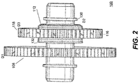
- Fig. 2 shows the gear assembly 100 in an assembled manner.
- the first gear 108 is shown having a larger primary diameter (D1) than the outer diameter (D2) of the second gear 112, also first gear 108 of the first gear wheel 102 includes a larger primary diameter (D1) than the diameter (D3) outer gear 118 of the second gear wheel 116.
- D3 is larger than D1
- D2 is larger than D1
- the second gear 112 of the first gear wheel 102 is wider along the primary axis 106 than the second gear wheel 116. This feature further allows the second gear wheel 116 to be positioned in multiple locations along the second gear 112 of the first gear wheel 102, and be adaptable to multiple configurations and applications.
- arrangement of the splined gears provides an axial thrust load.
- torque is applied from either the first gear wheel 102 or from the second gear wheel 116 that gear pushes axially into the shoulder of the other gear. If the torque is reversed the force goes into the retention member 128. Reversing the orientation of the spline of the gears allows the loads to be reversed as well. For example, as long as the torque is always the same way for an application a user is able to select which component takes the thrust load, a gear or retaining member, locking in the timing consistently for each load application.
- the gear assembly 100 allows for a simple method of assembly without needing to welding and grinding.
- the assembly process allows for simply threading the second gear wheel 116 onto the first gear wheel 102, measuring the timing of the system without the shims 126, and if necessary removing the second gear wheel 116 and adding the appropriate number or thicknesses of shims 126 to appropriately position the second gear wheel 116 along axis 106, and installing remaining shims on the opposite side of the second gear wheel 116 to minimize the space between retention member 128 and the second gear wheel 116.
Landscapes
- Engineering & Computer Science (AREA)
- General Engineering & Computer Science (AREA)
- Mechanical Engineering (AREA)
- Gear Transmission (AREA)
- Gears, Cams (AREA)
Abstract
Description
- The present disclosure relates to a cluster gear, and more particularly to a cluster gear assembly including a cluster gear kit adaptable for multiple configurations.
- A variety of gear arrangements are known, such as planetary and cluster gears. However, arranging multiple cluster or planetary gears together requires precise timing, which can be very costly and time consuming. Aligning teeth of gears of different diameters is a very time consuming task for any assembly shop. Also, this process typically requires welding, followed by a post-grind operation, and grouping of similarly timed gears. Accordingly, there is a need in the art for a gear arrangement having improved adaptability. There also is a need in the art for such gear assemblies and components to be economically viable. The present disclosure addresses these needs.
- A gear set includes a first gear wheel comprising a shaft bore defining a primary axis, including a first gear wherein teeth of the first gear are oriented parallel to the primary axis and a second gear wherein teeth of the second gear are oriented not-parallel to the primary axis, a second gear wheel configured to match the second gear of the first gear wheel including an outer gear wherein teeth of the outer gear are oriented parallel to the primary axis and an inner gear wherein teeth of the inner gear are oriented parallel to the second gear teeth, at least one shim configured to appropriately locate the second gear wheel on the first gear wheel, and a retention member, such as the retention member is a retaining ring, a locknut, or a pressed on bearing, configured to secure the second gear and the at least one shim on the first gear wheel.
- The second gear of the first gear wheel and the inner gear of the second gear wheel can include helical splines. The first gear can have a larger primary diameter than the second gear and the first gear of the first gear wheel can include a larger primary diameter than the outer gear of the second gear wheel.
- The second gear of the first gear wheel can be wider along the primary axis than the second gear wheel. The at least one shim can include multiple shims, and include shims of different thicknesses. The first gear wheel can include a flange configured to separate the shim from the second gear and second flange configured to define a maximum position of the second gear wheel along the second gear of the first gear wheel.
- These and other features of the systems and methods of the subject disclosure will become more readily apparent to those skilled in the art from the following detailed description of the preferred embodiments taken in conjunction with the drawings.
- The following descriptions should not be considered limiting in any way. With reference to the accompanying drawings, like elements are numbered alike:
-
Fig. 1 is an exploded view of a gear assembly according to an embodiment of the disclosure; and -
Fig. 2 is a side view of the assembly ofFig. 1 showing the shims of the shim stack arranged along the second gear. - Reference will now be made to the drawings wherein like reference numerals identify similar structural features or aspects of the subject invention. For purposes of explanation and illustration, and not limitation, a partial view of an exemplary embodiment of a gear assembly in accordance with the disclosure is shown in
Fig. 1 and is designated generally byreference character 100. Other embodiments of the gear assembly in accordance with the invention, or aspects thereof, are provided inFigs. 2 as will be described. The methods and systems of the invention can be used to simplify gear retention and precision between different systems. -
Fig. 1 shows agear assembly 100 including afirst gear wheel 102, which includes ashaft bore 104 which defines aprimary axis 106. Thefirst gear wheel 102 further includes afirst gear 108 wherein teeth 110 of thefirst gear 108 are oriented parallel to theprimary axis 106 and asecond gear 112 whereinteeth 114 of thesecond gear 112 are oriented not-parallel to theprimary axis 106. Thegear assembly 100 also includes asecond gear wheel 116 meant to mate thesecond gear 112 of thefirst gear wheel 102. Thesecond gear wheel 116 includes anouter gear 118 whereinteeth 120 of theouter gear 118 are oriented parallel to theprimary axis 106 and aninner gear 122 wherein teeth 124 of theinner gear 122 are oriented parallel toteeth 114 of thesecond gear 112 of thefirst gear wheel 102. Thesecond gear 112 of thefirst gear wheel 102 and theinner gear 122 of thesecond gear wheel 116 mate and can form, for example, helical splines. -
Fig. 1 further shows a set ofshims 126 configured to appropriately locate thesecond gear wheel 116 along theshaft bore 104 and aretention member 128, such as a retaining ring, a locknut, or a pressed on bearing, to secure thesecond gear wheel 116 and the set ofshims 126. Thesecond gear wheel 116 has to be positioned on thefirst gear wheel 102 such that the second gear wheel lines up appropriately with other outer systems (not shown) and such that the teeth 110 of the first gear are aligned with theteeth 120 of thesecond gear wheel 116. This alignment is important for timing and torque transfer purposes of theassembly 100. When theassembly 100 is pressed together, when thefirst gear wheel 102 is held in place, and thesecond gear wheel 116 slides along theteeth 114 of thesecond gear 112, thesecond gear wheel 116 will rotate, allowing a user to locate and align theteeth 114 of the second gear and theteeth 120 of theouter gear 118 of thesecond gear wheel 116. Once the appropriate location of thesecond gear wheel 116 along thesecond gear 112 is identified, the second gear wheel can be secured with theshim 126. The ability to rotate thesecond gear wheel 116 circumferentially by changing its axial position along the spline of thesecond gear 112 saves machinists and assembly personnel a lot of time when assembling cluster gears. - The shims of the
shim pack 126 can be arranged as required in order to secure thesecond gear wheel 116. For instance inFig. 1 , two shims of differing thicknesses are placed on each side of thesecond gear wheel 116. The shims of theshim pack 126 can consist of varying thicknesses, it is also considered thatshim packs 126 can include shims of the same thickness. For example in a non-limiting configuration, in order to move thesecond gear wheel 116 closer to thefirst gear wheel 108 by 0.004 inches, a user would remove one 0.054 shim from one side of thesecond gear wheel 116 and swap it with a 0.050 shim from the second side of the second gear wheel. This allows an angular rotation between the gear teeth 110 and thegear teeth 120 to adjust timing following the angle of the helical spline. - Further shown in
Fig. 1 , aflange 130 on thefirs gear wheel 102 in order to help secure the retainingmember 128. The first gear wheel can include asecond flange 132 configured to define a maximum position of thesecond gear wheel 116 along thesecond gear 112 of thefirst gear wheel 102. -
Fig. 2 shows thegear assembly 100 in an assembled manner. Thefirst gear 108 is shown having a larger primary diameter (D1) than the outer diameter (D2) of thesecond gear 112, alsofirst gear 108 of thefirst gear wheel 102 includes a larger primary diameter (D1) than the diameter (D3)outer gear 118 of thesecond gear wheel 116. Although alternate embodiments wherein D3 is larger than D1 and D2 is larger than D1 are also possible. Thesecond gear 112 of thefirst gear wheel 102 is wider along theprimary axis 106 than thesecond gear wheel 116. This feature further allows thesecond gear wheel 116 to be positioned in multiple locations along thesecond gear 112 of thefirst gear wheel 102, and be adaptable to multiple configurations and applications. - Further, arrangement of the splined gears provides an axial thrust load. When torque is applied from either the
first gear wheel 102 or from thesecond gear wheel 116 that gear pushes axially into the shoulder of the other gear. If the torque is reversed the force goes into theretention member 128. Reversing the orientation of the spline of the gears allows the loads to be reversed as well. For example, as long as the torque is always the same way for an application a user is able to select which component takes the thrust load, a gear or retaining member, locking in the timing consistently for each load application. - The
gear assembly 100 allows for a simple method of assembly without needing to welding and grinding. The assembly process allows for simply threading thesecond gear wheel 116 onto thefirst gear wheel 102, measuring the timing of the system without theshims 126, and if necessary removing thesecond gear wheel 116 and adding the appropriate number or thicknesses ofshims 126 to appropriately position thesecond gear wheel 116 alongaxis 106, and installing remaining shims on the opposite side of thesecond gear wheel 116 to minimize the space betweenretention member 128 and thesecond gear wheel 116. - The methods and systems of the present disclosure, as described above and shown in the drawings, provide for a gear assembly with superior properties including increased reliability and stability, and complexity, and/or cost. While the apparatus and methods of the subject disclosure have been shown and described with reference to certain exemplary embodiments, those skilled in the art will readily appreciate that changes and/or modifications may be made thereto without departing from the spirit and score of the subject disclosure.
Claims (15)
- A gear assembly (100) comprising:a first gear wheel (102) comprising a shaft bore (104) defining a primary axis (106), including a first gear (108) wherein a plurality of teeth (110) of the first gear are oriented in a first direction and a second gear (112) wherein a plurality of teeth (114) of the second gear are oriented not-parallel to the primary axis;a second gear wheel (116) configured to match the second gear of the first gear wheel including an outer gear (118) and an inner gear (122) wherein a plurality of teeth (124) of the inner gear are oriented parallel to the plurality of teeth of second gear; anda retention member (128) configured to secure the second gear wheel on the first gear wheel.
- The gear assembly of claim 1, further comprising at least one shim (126) configured to space the second gear wheel from the retention member or space the second gear wheel from the first gear wheel.
- The gear assembly of claim 2, wherein the at least one shim (126) includes a plurality of shims.
- The gear assembly of claim 3, further comprising shims (126) of different thicknesses; or further comprising shims (126) of equal thicknesses.
- The gear assembly of claim 3, wherein each of the shims (126) of the plurality of shims are interchangeable with one another.
- The gear assembly of any preceding claim, wherein the second gear (112) of the first gear wheel and the inner gear (122) of the second gear wheel are helical splines.
- The gear assembly of any preceding claim, wherein the first gear (108) includes a larger primary diameter than the second gear.
- The gear assembly of any preceding claim, wherein the first gear (108) of the first gear wheel includes a larger primary diameter than the outer gear (118) of the second gear wheel.
- The gear assembly of any preceding claim, wherein the retention member (128) is a retaining ring, a locknut, or a pressed on bearing.
- The gear assembly of any preceding claim, wherein the second gear (112) of the first gear wheel is wider along the primary axis than the second gear wheel (116).
- The gear assembly of any preceding claim, wherein the first gear wheel (102) includes a flange configured to separate the shim from the second gear.
- The gear assembly of any preceding claim, wherein the first gear wheel (102) includes a flange configured to define a maximum position of the second gear wheel along the second gear of the first gear wheel.
- The gear assembly of any preceding claim, wherein at least one of the plurality of teeth (110) of the first gear of the first gear wheel is aligned with at least one of the plurality of teeth (124) of the outer gear of the second gear wheel.
- The gear assembly of any preceding claim, wherein the plurality of teeth (110) of the first gear of the first gear wheel are aligned with the plurality of teeth (124) of the outer gear of the second wheel, and preferably wherein the plurality of teeth (110) of the first gear of the first gear wheel are parallel with the plurality of teeth (124) of the outer gear of the second wheel.
- The gear assembly of any preceding claim, wherein the plurality of teeth (110) of the first gear of the first gear wheel are parallel to the primary axis (126).
Applications Claiming Priority (1)
| Application Number | Priority Date | Filing Date | Title |
|---|---|---|---|
| US16/811,872 US11859693B2 (en) | 2020-03-06 | 2020-03-06 | Gear timing with helical spline and shims |
Publications (2)
| Publication Number | Publication Date |
|---|---|
| EP3875804A1 true EP3875804A1 (en) | 2021-09-08 |
| EP3875804B1 EP3875804B1 (en) | 2025-01-01 |
Family
ID=74758649
Family Applications (1)
| Application Number | Title | Priority Date | Filing Date |
|---|---|---|---|
| EP21159292.8A Active EP3875804B1 (en) | 2020-03-06 | 2021-02-25 | Double gear construction with helical splines and shims |
Country Status (2)
| Country | Link |
|---|---|
| US (1) | US11859693B2 (en) |
| EP (1) | EP3875804B1 (en) |
Citations (3)
| Publication number | Priority date | Publication date | Assignee | Title |
|---|---|---|---|---|
| DE102012007293A1 (en) * | 2011-04-12 | 2012-10-31 | Sumitomo Heavy Industries, Ltd. | Velocity and/or rotation speed changing device for use in speed reducing device for driving joint of industrial robot, has gear wheel formed as gear wheel body with large diameter fixed in radial direction outside tooth region |
| US20130199323A1 (en) * | 2012-02-07 | 2013-08-08 | Zhang-Hua Fong | Zero backlash gear structure |
| JP6424770B2 (en) * | 2015-08-06 | 2018-11-21 | トヨタ自動車株式会社 | Mountain gear |
Family Cites Families (17)
| Publication number | Priority date | Publication date | Assignee | Title |
|---|---|---|---|---|
| US3586144A (en) * | 1969-06-02 | 1971-06-22 | William C Rogers | Mechanical movement and control mechanism employing the same |
| US4017979A (en) * | 1975-10-09 | 1977-04-19 | Teledyne Industries, Inc. | Bevel gear shimming gage |
| JP2519218B2 (en) | 1986-09-13 | 1996-07-31 | 富士重工業株式会社 | Rotating device, preload adjusting method for rotating device, and adjusting device thereof |
| US4778303A (en) * | 1987-03-26 | 1988-10-18 | Dana Corporation | Quick change gear apparatus |
| US5000640A (en) * | 1988-03-28 | 1991-03-19 | Haas Jr Edward T | Split nut |
| JP2790286B2 (en) | 1988-07-20 | 1998-08-27 | マツダ株式会社 | Joining structure of annular parts |
| US5069654A (en) * | 1990-11-30 | 1991-12-03 | Jepmar Research | System for drivingly connecting gears, pulleys, wheels, rollers and other apertured components to shafts |
| US7210366B2 (en) * | 2004-12-08 | 2007-05-01 | 4×4 Tech Incorporated | Full support mainshaft and fifth gear design |
| US20070111841A1 (en) | 2005-10-19 | 2007-05-17 | Smith Todd A | Axle assembly bearing positioning and preload adjustment tool and method of implementing same |
| JP2009138916A (en) * | 2007-12-11 | 2009-06-25 | Enplas Corp | Backlashless gear device |
| DE102009052791A1 (en) * | 2009-11-11 | 2011-07-07 | Knorr-Bremse Systeme für Nutzfahrzeuge GmbH, 80809 | Device for coupling a drive shaft of an accessory of a commercial vehicle with a gear drive and method for producing this device |
| CN202659872U (en) | 2012-07-13 | 2013-01-09 | 中国重汽集团济南动力有限公司 | Secondary box structure of transmission planetary gear train |
| US8720113B1 (en) * | 2012-11-02 | 2014-05-13 | Paul Jules Krivoy | Non-handed swing door operator |
| JP2015068498A (en) * | 2013-10-01 | 2015-04-13 | 株式会社ジェイテクト | Gear device |
| US20180187759A1 (en) * | 2017-01-05 | 2018-07-05 | Thomson Linear Llc | Heavy duty electro-mechanical linear actuator |
| EP3527840A1 (en) * | 2018-02-20 | 2019-08-21 | Ningbo Geely Automobile Research & Development Co., Ltd. | A gear wheel |
| DE102018115172A1 (en) * | 2018-06-25 | 2020-01-02 | Schaeffler Technologies AG & Co. KG | Multiple planetary shaft, method, drive train section with the multiple planetary shaft and electrical axis with the drive train section and / or the multiple planetary shaft |
-
2020
- 2020-03-06 US US16/811,872 patent/US11859693B2/en active Active
-
2021
- 2021-02-25 EP EP21159292.8A patent/EP3875804B1/en active Active
Patent Citations (3)
| Publication number | Priority date | Publication date | Assignee | Title |
|---|---|---|---|---|
| DE102012007293A1 (en) * | 2011-04-12 | 2012-10-31 | Sumitomo Heavy Industries, Ltd. | Velocity and/or rotation speed changing device for use in speed reducing device for driving joint of industrial robot, has gear wheel formed as gear wheel body with large diameter fixed in radial direction outside tooth region |
| US20130199323A1 (en) * | 2012-02-07 | 2013-08-08 | Zhang-Hua Fong | Zero backlash gear structure |
| JP6424770B2 (en) * | 2015-08-06 | 2018-11-21 | トヨタ自動車株式会社 | Mountain gear |
Also Published As
| Publication number | Publication date |
|---|---|
| US11859693B2 (en) | 2024-01-02 |
| EP3875804B1 (en) | 2025-01-01 |
| US20210277978A1 (en) | 2021-09-09 |
Similar Documents
| Publication | Publication Date | Title |
|---|---|---|
| US10612585B2 (en) | Angular contact bearing and gear mechanism comprising a thrust washer | |
| EP2772664B1 (en) | Planetary reduction gear and series of the same | |
| CN101377230A (en) | Planetary transmission having double helical teeth | |
| US20130065696A1 (en) | Flexible diaphragm coupling for axial force loading | |
| US10415672B2 (en) | Drives with partial cycloid teeth profile | |
| US9771983B2 (en) | Coupling assembly | |
| JP6153769B2 (en) | Cam device | |
| US20160236511A1 (en) | Extended length bearing cone system | |
| US20180161945A1 (en) | Bolt fastening apparatus | |
| US10823258B2 (en) | Planetary transmission | |
| EP2875247B1 (en) | Permanent visual indicator and diametrical to axial relation gage and method of using same | |
| EP3875804B1 (en) | Double gear construction with helical splines and shims | |
| CN108368933A (en) | Transmission and drive unit with transmission | |
| US7479087B2 (en) | Pinion shaft and differential housing assembly | |
| US20070223994A1 (en) | Integrated locking device | |
| US20100087263A1 (en) | Splined couplings | |
| EP4001693B1 (en) | Friction tubes | |
| US7309187B2 (en) | Releasable keyless bushing assembly | |
| EP0020517B1 (en) | Expandable arbor for holding a stack of elements | |
| US10495152B2 (en) | Coupling assembly | |
| US12215745B1 (en) | Torque transferring coupler | |
| US8776639B2 (en) | Spur gear power sharing gear sets | |
| DE102015120240B3 (en) | Coupling element for cycloidal gear | |
| US3995448A (en) | Torsionally resilient shaft coupling | |
| EP2891833B1 (en) | Carrier shaft set |
Legal Events
| Date | Code | Title | Description |
|---|---|---|---|
| PUAI | Public reference made under article 153(3) epc to a published international application that has entered the european phase |
Free format text: ORIGINAL CODE: 0009012 |
|
| STAA | Information on the status of an ep patent application or granted ep patent |
Free format text: STATUS: THE APPLICATION HAS BEEN PUBLISHED |
|
| AK | Designated contracting states |
Kind code of ref document: A1 Designated state(s): AL AT BE BG CH CY CZ DE DK EE ES FI FR GB GR HR HU IE IS IT LI LT LU LV MC MK MT NL NO PL PT RO RS SE SI SK SM TR |
|
| STAA | Information on the status of an ep patent application or granted ep patent |
Free format text: STATUS: REQUEST FOR EXAMINATION WAS MADE |
|
| 17P | Request for examination filed |
Effective date: 20220307 |
|
| RBV | Designated contracting states (corrected) |
Designated state(s): AL AT BE BG CH CY CZ DE DK EE ES FI FR GB GR HR HU IE IS IT LI LT LU LV MC MK MT NL NO PL PT RO RS SE SI SK SM TR |
|
| STAA | Information on the status of an ep patent application or granted ep patent |
Free format text: STATUS: EXAMINATION IS IN PROGRESS |
|
| 17Q | First examination report despatched |
Effective date: 20230310 |
|
| GRAP | Despatch of communication of intention to grant a patent |
Free format text: ORIGINAL CODE: EPIDOSNIGR1 |
|
| STAA | Information on the status of an ep patent application or granted ep patent |
Free format text: STATUS: GRANT OF PATENT IS INTENDED |
|
| INTG | Intention to grant announced |
Effective date: 20240912 |
|
| GRAS | Grant fee paid |
Free format text: ORIGINAL CODE: EPIDOSNIGR3 |
|
| GRAA | (expected) grant |
Free format text: ORIGINAL CODE: 0009210 |
|
| STAA | Information on the status of an ep patent application or granted ep patent |
Free format text: STATUS: THE PATENT HAS BEEN GRANTED |
|
| AK | Designated contracting states |
Kind code of ref document: B1 Designated state(s): AL AT BE BG CH CY CZ DE DK EE ES FI FR GB GR HR HU IE IS IT LI LT LU LV MC MK MT NL NO PL PT RO RS SE SI SK SM TR |
|
| REG | Reference to a national code |
Ref country code: GB Ref legal event code: FG4D |
|
| REG | Reference to a national code |
Ref country code: CH Ref legal event code: EP |
|
| REG | Reference to a national code |
Ref country code: DE Ref legal event code: R096 Ref document number: 602021024084 Country of ref document: DE |
|
| REG | Reference to a national code |
Ref country code: IE Ref legal event code: FG4D |
|
| PGFP | Annual fee paid to national office [announced via postgrant information from national office to epo] |
Ref country code: AT Payment date: 20250417 Year of fee payment: 5 |
|
| REG | Reference to a national code |
Ref country code: LT Ref legal event code: MG9D |
|
| REG | Reference to a national code |
Ref country code: NL Ref legal event code: MP Effective date: 20250101 |
|
| REG | Reference to a national code |
Ref country code: AT Ref legal event code: MK05 Ref document number: 1756543 Country of ref document: AT Kind code of ref document: T Effective date: 20250101 |
|
| PG25 | Lapsed in a contracting state [announced via postgrant information from national office to epo] |
Ref country code: NL Free format text: LAPSE BECAUSE OF FAILURE TO SUBMIT A TRANSLATION OF THE DESCRIPTION OR TO PAY THE FEE WITHIN THE PRESCRIBED TIME-LIMIT Effective date: 20250101 |
|
| PG25 | Lapsed in a contracting state [announced via postgrant information from national office to epo] |
Ref country code: FI Free format text: LAPSE BECAUSE OF FAILURE TO SUBMIT A TRANSLATION OF THE DESCRIPTION OR TO PAY THE FEE WITHIN THE PRESCRIBED TIME-LIMIT Effective date: 20250101 |
|
| PG25 | Lapsed in a contracting state [announced via postgrant information from national office to epo] |
Ref country code: PL Free format text: LAPSE BECAUSE OF FAILURE TO SUBMIT A TRANSLATION OF THE DESCRIPTION OR TO PAY THE FEE WITHIN THE PRESCRIBED TIME-LIMIT Effective date: 20250101 |
|
| PG25 | Lapsed in a contracting state [announced via postgrant information from national office to epo] |
Ref country code: ES Free format text: LAPSE BECAUSE OF FAILURE TO SUBMIT A TRANSLATION OF THE DESCRIPTION OR TO PAY THE FEE WITHIN THE PRESCRIBED TIME-LIMIT Effective date: 20250101 |
|
| PG25 | Lapsed in a contracting state [announced via postgrant information from national office to epo] |
Ref country code: NO Free format text: LAPSE BECAUSE OF FAILURE TO SUBMIT A TRANSLATION OF THE DESCRIPTION OR TO PAY THE FEE WITHIN THE PRESCRIBED TIME-LIMIT Effective date: 20250401 Ref country code: IS Free format text: LAPSE BECAUSE OF FAILURE TO SUBMIT A TRANSLATION OF THE DESCRIPTION OR TO PAY THE FEE WITHIN THE PRESCRIBED TIME-LIMIT Effective date: 20250501 |
|
| PG25 | Lapsed in a contracting state [announced via postgrant information from national office to epo] |
Ref country code: HR Free format text: LAPSE BECAUSE OF FAILURE TO SUBMIT A TRANSLATION OF THE DESCRIPTION OR TO PAY THE FEE WITHIN THE PRESCRIBED TIME-LIMIT Effective date: 20250101 |
|
| PG25 | Lapsed in a contracting state [announced via postgrant information from national office to epo] |
Ref country code: LV Free format text: LAPSE BECAUSE OF FAILURE TO SUBMIT A TRANSLATION OF THE DESCRIPTION OR TO PAY THE FEE WITHIN THE PRESCRIBED TIME-LIMIT Effective date: 20250101 Ref country code: PT Free format text: LAPSE BECAUSE OF FAILURE TO SUBMIT A TRANSLATION OF THE DESCRIPTION OR TO PAY THE FEE WITHIN THE PRESCRIBED TIME-LIMIT Effective date: 20250502 |
|
| PG25 | Lapsed in a contracting state [announced via postgrant information from national office to epo] |
Ref country code: GR Free format text: LAPSE BECAUSE OF FAILURE TO SUBMIT A TRANSLATION OF THE DESCRIPTION OR TO PAY THE FEE WITHIN THE PRESCRIBED TIME-LIMIT Effective date: 20250402 Ref country code: BG Free format text: LAPSE BECAUSE OF FAILURE TO SUBMIT A TRANSLATION OF THE DESCRIPTION OR TO PAY THE FEE WITHIN THE PRESCRIBED TIME-LIMIT Effective date: 20250101 |
|
| PG25 | Lapsed in a contracting state [announced via postgrant information from national office to epo] |
Ref country code: AT Free format text: LAPSE BECAUSE OF FAILURE TO SUBMIT A TRANSLATION OF THE DESCRIPTION OR TO PAY THE FEE WITHIN THE PRESCRIBED TIME-LIMIT Effective date: 20250101 |
|
| PG25 | Lapsed in a contracting state [announced via postgrant information from national office to epo] |
Ref country code: CZ Free format text: LAPSE BECAUSE OF FAILURE TO SUBMIT A TRANSLATION OF THE DESCRIPTION OR TO PAY THE FEE WITHIN THE PRESCRIBED TIME-LIMIT Effective date: 20250101 |
|
| PG25 | Lapsed in a contracting state [announced via postgrant information from national office to epo] |
Ref country code: SE Free format text: LAPSE BECAUSE OF FAILURE TO SUBMIT A TRANSLATION OF THE DESCRIPTION OR TO PAY THE FEE WITHIN THE PRESCRIBED TIME-LIMIT Effective date: 20250101 |
|
| REG | Reference to a national code |
Ref country code: CH Ref legal event code: PL |
|
| REG | Reference to a national code |
Ref country code: DE Ref legal event code: R097 Ref document number: 602021024084 Country of ref document: DE |
|
| PG25 | Lapsed in a contracting state [announced via postgrant information from national office to epo] |
Ref country code: SM Free format text: LAPSE BECAUSE OF FAILURE TO SUBMIT A TRANSLATION OF THE DESCRIPTION OR TO PAY THE FEE WITHIN THE PRESCRIBED TIME-LIMIT Effective date: 20250101 |
|
| PG25 | Lapsed in a contracting state [announced via postgrant information from national office to epo] |
Ref country code: DK Free format text: LAPSE BECAUSE OF FAILURE TO SUBMIT A TRANSLATION OF THE DESCRIPTION OR TO PAY THE FEE WITHIN THE PRESCRIBED TIME-LIMIT Effective date: 20250101 |
|
| PG25 | Lapsed in a contracting state [announced via postgrant information from national office to epo] |
Ref country code: MC Free format text: LAPSE BECAUSE OF FAILURE TO SUBMIT A TRANSLATION OF THE DESCRIPTION OR TO PAY THE FEE WITHIN THE PRESCRIBED TIME-LIMIT Effective date: 20250101 |
|
| PG25 | Lapsed in a contracting state [announced via postgrant information from national office to epo] |
Ref country code: IT Free format text: LAPSE BECAUSE OF FAILURE TO SUBMIT A TRANSLATION OF THE DESCRIPTION OR TO PAY THE FEE WITHIN THE PRESCRIBED TIME-LIMIT Effective date: 20250101 Ref country code: LU Free format text: LAPSE BECAUSE OF NON-PAYMENT OF DUE FEES Effective date: 20250225 |
|
| PG25 | Lapsed in a contracting state [announced via postgrant information from national office to epo] |
Ref country code: CH Free format text: LAPSE BECAUSE OF NON-PAYMENT OF DUE FEES Effective date: 20250228 |
|
| PG25 | Lapsed in a contracting state [announced via postgrant information from national office to epo] |
Ref country code: EE Free format text: LAPSE BECAUSE OF FAILURE TO SUBMIT A TRANSLATION OF THE DESCRIPTION OR TO PAY THE FEE WITHIN THE PRESCRIBED TIME-LIMIT Effective date: 20250101 |
|
| PG25 | Lapsed in a contracting state [announced via postgrant information from national office to epo] |
Ref country code: RO Free format text: LAPSE BECAUSE OF FAILURE TO SUBMIT A TRANSLATION OF THE DESCRIPTION OR TO PAY THE FEE WITHIN THE PRESCRIBED TIME-LIMIT Effective date: 20250101 |
|
| PG25 | Lapsed in a contracting state [announced via postgrant information from national office to epo] |
Ref country code: SK Free format text: LAPSE BECAUSE OF FAILURE TO SUBMIT A TRANSLATION OF THE DESCRIPTION OR TO PAY THE FEE WITHIN THE PRESCRIBED TIME-LIMIT Effective date: 20250101 |
|
| PLBE | No opposition filed within time limit |
Free format text: ORIGINAL CODE: 0009261 |
|
| STAA | Information on the status of an ep patent application or granted ep patent |
Free format text: STATUS: NO OPPOSITION FILED WITHIN TIME LIMIT |
|
| REG | Reference to a national code |
Ref country code: BE Ref legal event code: MM Effective date: 20250228 |
|
| 26N | No opposition filed |
Effective date: 20251002 |
|
| PG25 | Lapsed in a contracting state [announced via postgrant information from national office to epo] |
Ref country code: BE Free format text: LAPSE BECAUSE OF NON-PAYMENT OF DUE FEES Effective date: 20250228 |
|
| PG25 | Lapsed in a contracting state [announced via postgrant information from national office to epo] |
Ref country code: IE Free format text: LAPSE BECAUSE OF NON-PAYMENT OF DUE FEES Effective date: 20250225 |
|
| PGFP | Annual fee paid to national office [announced via postgrant information from national office to epo] |
Ref country code: GB Payment date: 20260121 Year of fee payment: 6 |
|
| PGFP | Annual fee paid to national office [announced via postgrant information from national office to epo] |
Ref country code: DE Payment date: 20260121 Year of fee payment: 6 |
|
| PGFP | Annual fee paid to national office [announced via postgrant information from national office to epo] |
Ref country code: FR Payment date: 20260121 Year of fee payment: 6 |