EP3875803A1 - Transmission apparatus comprising gear reversal for means of transport, preferably pedal means of transport - Google Patents
Transmission apparatus comprising gear reversal for means of transport, preferably pedal means of transport Download PDFInfo
- Publication number
- EP3875803A1 EP3875803A1 EP21159910.5A EP21159910A EP3875803A1 EP 3875803 A1 EP3875803 A1 EP 3875803A1 EP 21159910 A EP21159910 A EP 21159910A EP 3875803 A1 EP3875803 A1 EP 3875803A1
- Authority
- EP
- European Patent Office
- Prior art keywords
- transmission
- transmission shaft
- shaft
- gear
- activation
- Prior art date
- Legal status (The legal status is an assumption and is not a legal conclusion. Google has not performed a legal analysis and makes no representation as to the accuracy of the status listed.)
- Granted
Links
- 230000005540 biological transmission Effects 0.000 title claims abstract description 321
- 230000004913 activation Effects 0.000 claims abstract description 78
- 230000033001 locomotion Effects 0.000 claims description 46
- 230000002441 reversible effect Effects 0.000 claims description 41
- 239000000463 material Substances 0.000 claims description 12
- 238000003780 insertion Methods 0.000 claims description 10
- 230000037431 insertion Effects 0.000 claims description 10
- 238000000605 extraction Methods 0.000 claims description 6
- 230000009471 action Effects 0.000 description 3
- 230000008859 change Effects 0.000 description 3
- 230000003247 decreasing effect Effects 0.000 description 2
- 230000001419 dependent effect Effects 0.000 description 2
- 229920001971 elastomer Polymers 0.000 description 2
- 230000001939 inductive effect Effects 0.000 description 2
- 230000003993 interaction Effects 0.000 description 2
- 230000003287 optical effect Effects 0.000 description 2
- 244000025254 Cannabis sativa Species 0.000 description 1
- 241001331845 Equus asinus x caballus Species 0.000 description 1
- 239000000654 additive Substances 0.000 description 1
- 230000000996 additive effect Effects 0.000 description 1
- 230000001174 ascending effect Effects 0.000 description 1
- 230000000903 blocking effect Effects 0.000 description 1
- 230000008878 coupling Effects 0.000 description 1
- 238000010168 coupling process Methods 0.000 description 1
- 238000005859 coupling reaction Methods 0.000 description 1
- 239000000428 dust Substances 0.000 description 1
- 238000009429 electrical wiring Methods 0.000 description 1
- 238000009434 installation Methods 0.000 description 1
- 238000003754 machining Methods 0.000 description 1
- 230000007246 mechanism Effects 0.000 description 1
- 238000000034 method Methods 0.000 description 1
- 230000004048 modification Effects 0.000 description 1
- 238000012986 modification Methods 0.000 description 1
- 239000004033 plastic Substances 0.000 description 1
- 229920003023 plastic Polymers 0.000 description 1
- 229920001296 polysiloxane Polymers 0.000 description 1
- 229920002635 polyurethane Polymers 0.000 description 1
- 239000004814 polyurethane Substances 0.000 description 1
- 230000008569 process Effects 0.000 description 1
Images


Classifications
-
- B—PERFORMING OPERATIONS; TRANSPORTING
- B62—LAND VEHICLES FOR TRAVELLING OTHERWISE THAN ON RAILS
- B62M—RIDER PROPULSION OF WHEELED VEHICLES OR SLEDGES; POWERED PROPULSION OF SLEDGES OR SINGLE-TRACK CYCLES; TRANSMISSIONS SPECIALLY ADAPTED FOR SUCH VEHICLES
- B62M6/00—Rider propulsion of wheeled vehicles with additional source of power, e.g. combustion engine or electric motor
- B62M6/40—Rider propelled cycles with auxiliary electric motor
- B62M6/55—Rider propelled cycles with auxiliary electric motor power-driven at crank shafts parts
-
- B—PERFORMING OPERATIONS; TRANSPORTING
- B62—LAND VEHICLES FOR TRAVELLING OTHERWISE THAN ON RAILS
- B62M—RIDER PROPULSION OF WHEELED VEHICLES OR SLEDGES; POWERED PROPULSION OF SLEDGES OR SINGLE-TRACK CYCLES; TRANSMISSIONS SPECIALLY ADAPTED FOR SUCH VEHICLES
- B62M11/00—Transmissions characterised by the use of interengaging toothed wheels or frictionally-engaging wheels
- B62M11/04—Transmissions characterised by the use of interengaging toothed wheels or frictionally-engaging wheels of changeable ratio
- B62M11/06—Transmissions characterised by the use of interengaging toothed wheels or frictionally-engaging wheels of changeable ratio with spur gear wheels
-
- F—MECHANICAL ENGINEERING; LIGHTING; HEATING; WEAPONS; BLASTING
- F16—ENGINEERING ELEMENTS AND UNITS; GENERAL MEASURES FOR PRODUCING AND MAINTAINING EFFECTIVE FUNCTIONING OF MACHINES OR INSTALLATIONS; THERMAL INSULATION IN GENERAL
- F16H—GEARING
- F16H3/00—Toothed gearings for conveying rotary motion with variable gear ratio or for reversing rotary motion
- F16H3/02—Toothed gearings for conveying rotary motion with variable gear ratio or for reversing rotary motion without gears having orbital motion
- F16H3/08—Toothed gearings for conveying rotary motion with variable gear ratio or for reversing rotary motion without gears having orbital motion exclusively or essentially with continuously meshing gears, that can be disengaged from their shafts
- F16H3/087—Toothed gearings for conveying rotary motion with variable gear ratio or for reversing rotary motion without gears having orbital motion exclusively or essentially with continuously meshing gears, that can be disengaged from their shafts characterised by the disposition of the gears
- F16H3/089—Toothed gearings for conveying rotary motion with variable gear ratio or for reversing rotary motion without gears having orbital motion exclusively or essentially with continuously meshing gears, that can be disengaged from their shafts characterised by the disposition of the gears all of the meshing gears being supported by a pair of parallel shafts, one being the input shaft and the other the output shaft, there being no countershaft involved
-
- F—MECHANICAL ENGINEERING; LIGHTING; HEATING; WEAPONS; BLASTING
- F16—ENGINEERING ELEMENTS AND UNITS; GENERAL MEASURES FOR PRODUCING AND MAINTAINING EFFECTIVE FUNCTIONING OF MACHINES OR INSTALLATIONS; THERMAL INSULATION IN GENERAL
- F16H—GEARING
- F16H61/00—Control functions within control units of change-speed- or reversing-gearings for conveying rotary motion ; Control of exclusively fluid gearing, friction gearing, gearings with endless flexible members or other particular types of gearing
- F16H61/02—Control functions within control units of change-speed- or reversing-gearings for conveying rotary motion ; Control of exclusively fluid gearing, friction gearing, gearings with endless flexible members or other particular types of gearing characterised by the signals used
- F16H61/0202—Control functions within control units of change-speed- or reversing-gearings for conveying rotary motion ; Control of exclusively fluid gearing, friction gearing, gearings with endless flexible members or other particular types of gearing characterised by the signals used the signals being electric
- F16H61/0204—Control functions within control units of change-speed- or reversing-gearings for conveying rotary motion ; Control of exclusively fluid gearing, friction gearing, gearings with endless flexible members or other particular types of gearing characterised by the signals used the signals being electric for gearshift control, e.g. control functions for performing shifting or generation of shift signal
- F16H61/0246—Control functions within control units of change-speed- or reversing-gearings for conveying rotary motion ; Control of exclusively fluid gearing, friction gearing, gearings with endless flexible members or other particular types of gearing characterised by the signals used the signals being electric for gearshift control, e.g. control functions for performing shifting or generation of shift signal characterised by initiating reverse gearshift
-
- F—MECHANICAL ENGINEERING; LIGHTING; HEATING; WEAPONS; BLASTING
- F16—ENGINEERING ELEMENTS AND UNITS; GENERAL MEASURES FOR PRODUCING AND MAINTAINING EFFECTIVE FUNCTIONING OF MACHINES OR INSTALLATIONS; THERMAL INSULATION IN GENERAL
- F16H—GEARING
- F16H63/00—Control outputs from the control unit to change-speed- or reversing-gearings for conveying rotary motion or to other devices than the final output mechanism
- F16H63/02—Final output mechanisms therefor; Actuating means for the final output mechanisms
- F16H63/08—Multiple final output mechanisms being moved by a single common final actuating mechanism
- F16H63/16—Multiple final output mechanisms being moved by a single common final actuating mechanism the final output mechanisms being successively actuated by progressive movement of the final actuating mechanism
- F16H63/18—Multiple final output mechanisms being moved by a single common final actuating mechanism the final output mechanisms being successively actuated by progressive movement of the final actuating mechanism the final actuating mechanism comprising cams
-
- F—MECHANICAL ENGINEERING; LIGHTING; HEATING; WEAPONS; BLASTING
- F16—ENGINEERING ELEMENTS AND UNITS; GENERAL MEASURES FOR PRODUCING AND MAINTAINING EFFECTIVE FUNCTIONING OF MACHINES OR INSTALLATIONS; THERMAL INSULATION IN GENERAL
- F16H—GEARING
- F16H63/00—Control outputs from the control unit to change-speed- or reversing-gearings for conveying rotary motion or to other devices than the final output mechanism
- F16H63/02—Final output mechanisms therefor; Actuating means for the final output mechanisms
- F16H63/30—Constructional features of the final output mechanisms
- F16H63/304—Constructional features of the final output mechanisms the final output mechanisms comprising elements moved by electrical or magnetic force
-
- B—PERFORMING OPERATIONS; TRANSPORTING
- B62—LAND VEHICLES FOR TRAVELLING OTHERWISE THAN ON RAILS
- B62K—CYCLES; CYCLE FRAMES; CYCLE STEERING DEVICES; RIDER-OPERATED TERMINAL CONTROLS SPECIALLY ADAPTED FOR CYCLES; CYCLE AXLE SUSPENSIONS; CYCLE SIDE-CARS, FORECARS, OR THE LIKE
- B62K7/00—Freight- or passenger-carrying cycles
-
- B—PERFORMING OPERATIONS; TRANSPORTING
- B62—LAND VEHICLES FOR TRAVELLING OTHERWISE THAN ON RAILS
- B62M—RIDER PROPULSION OF WHEELED VEHICLES OR SLEDGES; POWERED PROPULSION OF SLEDGES OR SINGLE-TRACK CYCLES; TRANSMISSIONS SPECIALLY ADAPTED FOR SUCH VEHICLES
- B62M11/00—Transmissions characterised by the use of interengaging toothed wheels or frictionally-engaging wheels
- B62M11/04—Transmissions characterised by the use of interengaging toothed wheels or frictionally-engaging wheels of changeable ratio
- B62M11/14—Transmissions characterised by the use of interengaging toothed wheels or frictionally-engaging wheels of changeable ratio with planetary gears
-
- F—MECHANICAL ENGINEERING; LIGHTING; HEATING; WEAPONS; BLASTING
- F16—ENGINEERING ELEMENTS AND UNITS; GENERAL MEASURES FOR PRODUCING AND MAINTAINING EFFECTIVE FUNCTIONING OF MACHINES OR INSTALLATIONS; THERMAL INSULATION IN GENERAL
- F16H—GEARING
- F16H2200/00—Transmissions for multiple ratios
- F16H2200/003—Transmissions for multiple ratios characterised by the number of forward speeds
- F16H2200/0047—Transmissions for multiple ratios characterised by the number of forward speeds the gear ratios comprising five forward speeds
Definitions
- the present invention relates to a transmission apparatus comprising gear reversal for means of transport, preferably pedal means of transport.
- the present invention relates to a transmission ratio selection apparatus capable of implementing a reversal of travel direction and/or a change of speed for means of transport, preferably bicycles and cargobikes.
- the present invention is applied to bicycles and, therefore, reference below will mainly be made to an apparatus for changing the travel direction for bicycles.
- a speed change device could be applied on any means of transport such as, for example, motor vehicles or non-motorised vehicles.
- the present invention relates to an apparatus for changing the travel direction for bicycles adapted to both purely urban use and/or on roads with uniform surface and with minimum unevenness and for extreme/sports use, i.e., for bicycles arranged for use on more uneven surfaces such as cobblestones, mule tracks or trails on dirt or grass.
- bicycles are generally provided with a gearbox to make the use of the bicycle more effective, for example if the bicycle must face ascents, unevenness in general or a heavy load must be transported which requires greater effort during the user's pedalling.
- the technical task of the present invention is to propose a transmission apparatus comprising gear reversal for means of transport, preferably pedal means of transport, which obviates the drawbacks of the known art as mentioned above.
- an object of the present invention is to provide a transmission apparatus for gear reversal for means of transport capable of allowing a user a simple mechanism for reversing the travel direction of the pedal vehicle used.
- an object of the present invention is to provide an apparatus for gear reversal capable of reversing the rotation of the shaft directly connected to the wheels without changing the rotation direction of the leading drive shaft or the shaft of the pedal cranks.
- the purpose of the apparatus for gear reversal according to the present invention is to allow the reversal of the pedal vehicle on which it is installed without reversing the rotation direction of the cyclist's pedalling.
- one of the objects of the apparatus for gear reversal according to the present invention is to provide a transmission system in which reversal is not achieved by the reversal of the rotation direction of the shaft of the pedal cranks by the user.
- the present invention relates to a transmission apparatus for gear reversal for means of transport, preferably pedal means of transport.
- the apparatus comprises a shaft of the pedal cranks, a second transmission shaft, a third transmission shaft, an activation device and motorisation means.
- the shaft of the pedal cranks is configured to rotate about an axis of the pedal cranks and comprises a main gear wheel configured to transfer the rotary motion of the shaft of the pedal cranks to a second transmission shaft by an inlet pinion engaged with the main gear wheel.
- the second transmission shaft is configured to rotate about a second longitudinal axis parallel to and spaced apart from the shaft of the pedal cranks.
- the second transmission shaft comprises a plurality of second transmission members integral therewith and arranged in sequence along the second longitudinal axis.
- the third transmission shaft is configured to rotate about a third longitudinal axis parallel to and spaced apart from the second longitudinal axis.
- the third transmission shaft comprises a plurality of third transmission members arranged in sequence along the third longitudinal axis, each of which is configurable between a non-selected condition, in which it is able to rotate freely about the third longitudinal axis, and a selected condition, in which it is able to rotate about the third longitudinal axis in a manner solidly constrained to the third transmission shaft.
- at least one of said third transmission members and at least one of said second transmission members are engaged with each other to establish a predetermined transmission ratio between the third transmission shaft and the second transmission shaft.
- the activation device is adapted to configure in the selected condition at most only one of the third transmission members to select the relative transmission ratio.
- the apparatus comprises a free wheel associated with the main gear wheel or with the inlet pinion, which is configured to rotate the main gear wheel or the inlet pinion integrally with the shaft of the pedal cranks when the latter rotates according to a main rotation direction corresponding to the main travel direction of the means of transport and not when the latter rotates according to a reverse rotation direction with respect to the main travel direction.
- the motorisation means is associated with at least one second transmission member or a tertiary gear wheel integral with the second transmission shaft.
- the motorisation means is configured to perform a movement of the second transmission shaft in accordance with the main travel direction and the reverse travel direction of the means of transport.
- the reverse travel direction is defined when the activation device has selected one of the second transmission members used for gear reversal engaged with a corresponding third transmission member also used for gear reversal so as to rotate the third transmission shaft in the opposite direction and not the shaft of the pedal cranks due to the presence of the aforementioned free wheel on the main gear wheel or on the inlet pinion.
- the invention also relates to a pedal vehicle comprising said transmission apparatus for gear reversal.
- the present invention relates to a transmission apparatus for gear reversal for means of transport, preferably pedal means of transport.
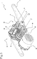
- Figure 1 illustrates a transmission apparatus 1 comprising gear reversal for means of transport, preferably pedal means of transport.
- the apparatus 1 comprises a shaft of the pedal cranks 10 (better seen at least in figure 2 ), a second transmission shaft 20, a third transmission shaft 30, an activation device 40 and a motorisation means 60 (better seen at least in figure 2 ).
- the third transmission shaft 30 is configured to rotate about a third longitudinal axis Z and a plurality of third transmission members 31, 32 arranged in sequence along the third longitudinal axis Z.
- Each third transmission member 31, 32 is advantageously configurable between a non-selected condition, in which it is able to rotate freely about the third longitudinal axis Z, and a selected condition, in which it is able to rotate about the third longitudinal axis Z in a manner solidly constrained with the third transmission shaft 30.
- the second transmission shaft 20 is configured to rotate about a second longitudinal axis Y parallel and spaced apart from the third longitudinal axis Z, and a plurality of second transmission members 21, 22 arranged in sequence along the second longitudinal axis Y and axially arranged at a respective third transmission member 31, 32 of the third transmission shaft 30.
- the second transmission members 21, 22 are integral in rotation with the second transmission shaft 20 about the second longitudinal axis Y.
- At least one of the third transmission members 31 and at least one of the second transmission members 21 are engaged with each other to establish a predetermined transmission ratio between the third transmission shaft 30 and the second transmission shaft 20.
- each of the third transmission members 31, 32 is engaged with a respective second transmission member 21, 22.
- the shaft of the pedal cranks 10 is configured to rotate about an axis of the pedal cranks X parallel to the third longitudinal axis Z and the second longitudinal axis Y. Furthermore, the shaft of the pedal cranks 10 comprises a main gear wheel 14 (better visible in figure 3 ) configured to transfer the rotary motion of the same shaft of the pedal cranks 10 to the second transmission shaft 20 by an inlet pinion 24 arranged on said second transmission shaft 20 and engaged with the main gear wheel 14.
- the main gear wheel 14 and the inlet pinion 24 are splined on the respective shaft so as to directly transfer a torque (for example deriving from pedalling) from the shaft of the pedal cranks 10 to the second transmission shaft 20.
- the inlet pinion 24 splined on the second transmission shaft 20 has dimensional and mechanical features which can be the same as or different from the second transmission members 21 adjacent thereto.
- the main gear wheel 14 or the inlet pinion 24 comprises a free wheel configured to rotate the main gear wheel 14 or the inlet pinion 24 in a manner solidly constrained to the shaft of the pedal cranks 10 when the latter rotates about the axis of the pedal cranks X according to a main rotation direction corresponding to the main travel direction opposite the reverse travel direction.
- the main gear wheel 14 comprises a free wheel configured to rotate the same main gear wheel 14 in a solidly constrained manner to said shaft of the pedal cranks 10 when the latter rotates about the axis of the pedal cranks X according to a main rotation direction corresponding to the main travel direction opposite the reverse travel direction.
- the inlet pinion 24 (and not the main gear wheel 14) comprises the free wheel configured to allow the transmission of motion only if the shaft of the pedal cranks 10 is rotated according to a predetermined rotation direction and not according to an opposite counter-rotation direction.
- the free wheel is advantageously associated with the pair of gears formed by the main gear wheel 14 and the inlet pinion 24 to allow the shaft of the pedal cranks 10 to transmit motion only when it rotates according to a preferred rotation direction and not according to an opposite direction.
- the free wheel is indistinctly directly associated with the main gear wheel 14 or the inlet pinion 24.
- the free wheel associated with the main gear wheel 14 allows the latter to transfer the torque generated by the cyclist's pedalling only if the pedalling is carried out according to a rotation direction which causes the advancement of the vehicle (regardless of the travel direction). If the cyclist's pedalling occurred in an opposite rotation direction, no force would be transferred to the second transmission shaft 20.
- the activation device 40 is operationally associated with the third transmission members 31,32 to configure in the selected condition at most only one of such third transmission members 31,32 to select the relative transmission ratio, for example forwards or in reverse if applied to a pedal vehicle 100.
- the motorisation means is associated with at least one second transmission member 21, 22 or with a tertiary gear wheel 25 mounted on the second transmission shaft 20 and integral in rotation therewith. Furthermore, the motorisation means is configured to achieve a movement in a main travel direction and in a reverse travel direction of the means of transport defined when the activation device 40 has selected one of the second transmission members used for gear reversal 22, which is engaged with a corresponding third transmission member also used for gear reversal 32, so as to rotate the third transmission shaft 30 in the opposite direction and not the shaft of the pedal cranks 10 due to the presence of the free wheel associated with the main gear wheel 14 or the inlet pinion 24.
- Figures 2 , 3 , 4 illustrate a first embodiment of the apparatus 1, in which the motorisation means comprises a gear reversal member 2, preferably an idler wheel, interposed and engaged between the second transmission member used for gear reversal 22 and the corresponding third transmission member used for gear reversal 32 so that the third and the second transmission shaft 30,20 have the same rotation direction when the third transmission member used for gear reversal 32 is configured in the selected condition.
- the motorisation means comprises a gear reversal member 2, preferably an idler wheel, interposed and engaged between the second transmission member used for gear reversal 22 and the corresponding third transmission member used for gear reversal 32 so that the third and the second transmission shaft 30,20 have the same rotation direction when the third transmission member used for gear reversal 32 is configured in the selected condition.
- the third transmission members 31, 32 are rotatably arranged along the third transmission shaft 30 independently of each other, so as to be able to rotate with different rotational speeds directly dependent on the respective transmission ratio defined by the coupling between the third and the second transmission member 31, 21, 32, 22. In addition, if they are configured in the non-selected condition, the third transmission members 31, 32 are able to rotate independently of the rotation of the same third transmission shaft 30.
- the apparatus 1 comprises at least one pair of transmission members 31, 21 such as to define a transmission ratio whereby the third transmission shaft 30 and the second transmission shaft 20 rotate according to two opposite rotation directions and at least one pair of transmission members used for gear reversal 32, 22 such as to define a transmission ratio whereby the third transmission shaft 30 and the second transmission shaft 20, through the interposition of the gear reversal member 2, rotate according to the same rotation direction so as to reverse the advancement direction of the vehicle.
- the pedalling of a cyclist rotates the second transmission shaft 20 and the relative second transmission members 21, 22 according to a main rotation direction, while the third transmission shaft 30 is rotated as a function of the third transmission member 31, 32 configured in the selected condition.
- the third transmission shaft 30 will rotate in a rotation direction opposite the preceding main rotation direction.
- the third transmission shaft 30 will rotate according to the same main rotation direction as the second transmission shaft 20.
- the travel direction of the pedal vehicle 100 provided with the apparatus 1 depends exclusively on which third transmission member 31, 32 is selected by the activation device 40, regardless of the rotation direction of the second transmission shaft 20, the latter generally always rotated by the shaft of the pedal cranks 10.
- the cyclist's pedalling and the consequent rotation of the second transmission shaft 20 will always occur in the same rotation direction regardless of the travel direction of the vehicle, while the selection or not of the third transmission member used for gear reversal 32 is able to determine the rotation of the third transmission shaft 30 in the forward or reverse direction of the pedal vehicle 100.
- the gear reversal member 2 comprises an idler wheel interposed and engaged between the third member used for gear reversal 32 and the second member used for gear reversal 22.
- the idler wheel which defines the gear reversal member 2 is engaged interposed between the third member used for gear reversal 32 and the second member used for gear reversal 22.
- Such engagement is constantly engaged as it is able to compensate for the reduced radial dimensions of the third and the second member used for gear reversal 32, 22.
- the third member used for gear reversal 32 rotates opposite the third transmission members 31 as they are all rotatably independent of each other.
- the first embodiment of the apparatus 1 can also comprise an electric assist motor 60 which is constantly engaged with the second transmission shaft 20 by a tertiary gear wheel 25 mounted on the same second transmission shaft 20. Consequently, the electric assist motor 60 and/or at least one of the second transmission members 21, 22 comprise at least one free wheel of the motor 64 configured to allow the transmission of the rotational motion from the electric assist motor 60 to the second transmission shaft 20 and, simultaneously, prevent the transmission of the motion from the second transmission shaft 20 to the electric assist motor 60.
- the free wheel of the motor 64 is configured to transmit a rotational motion from the electric assist motor 60 to the second transmission shaft 20 in accordance with a single rotation direction of the gears which form the electric assist motor 60.
- the free wheel of the motor 64 between the gears connecting them is advantageously arranged to prevent the cyclist from having to impart a force such as to rotate both the transmission shafts 30, 20 of the apparatus 1 and the gears of the electric assist motor 60 when the latter is deactivated.
- the electric assist motor 60 is advantageously configured to rotate at least the transmission shafts 30, 20 independently or to assist the pedalling of a cyclist.
- the motor upon configuration in the selected condition of a third transmission member 31, 32, the motor is able to activate the apparatus 1 and, therefore, move the vehicle in both travel directions as a function of the selected transmission ratio.
- Figures 5 and 6 illustrate a second embodiment of the apparatus 1, in which the motorisation means comprises an electric assist motor 60 engaged with a tertiary gear wheel 25 mounted on the second transmission shaft 20 and a control unit connected to the aforesaid electric assist motor 60. More specifically, the motorisation means lacks a gear reversal member, for example an idler wheel, interposed between the third member used for gear reversal 32 and the second member used for gear reversal 22.
- a gear reversal member for example an idler wheel
- the control unit is advantageously programmed to configure the electric assist motor 60 between a forward condition, in which it transmits to the shaft of the pedal cranks 10 and the third transmission shaft 30 a rotation in accordance with the main rotation direction, and a reverse condition, in which it transmits to the third transmission shaft 30 a rotation opposite the main rotation direction and, at the same time, does not transmit any rotation to the shaft of the pedal cranks 10.
- the electric assist motor 60 is kept active by the control unit both during advancement according to the main travel direction of the means of transport, and during advancement according to the reverse travel direction.
- the electric assist motor 60 does not have any free wheel and, at the same time, is engaged directly with at least a second transmission member 21, 22 or with the tertiary gear wheel 25.
- the electric assist motor 60 is activated to prevent the staticity thereof from providing a motor-brake to the user's pedalling.
- the greater the torque produced by the user during pedalling the greater the current supplied to the electric assist motor 60.
- control unit When it is desired to set the backward movement of the means of transport (i.e. the reverse movement according to the reverse travel direction), the control unit is programmed to reverse the movement of the electric assist motor 60 which, in turn, will reverse the rotation direction imparted to the second transmission shaft 20, inducing the reverse movement of the means of transport.
- the pedal cranks 4 will remain stationary by virtue of the presence of the free wheel on the main gear wheel 14 or on the inlet pinion 24.
- the control unit is configured to reverse the movement of the internal gears of the electric assist motor 60 so that the latter is able to alternate the rotation direction transmitted to the third transmission shaft 30, i.e., the shaft to which the drive wheel 5 (generally the rear wheel) of the means of transport is connected with a fixed snap connection by a transmission chain 7.
- the electric assist motor 60 (for example in the case of a pedal-assisted bicycle) is powered by an external electrical source to contribute at least partially to the movement of the transmission members 31, 21, in an operating condition of the apparatus 1.
- the electric assist motor 60 is able to operate both as an assistance and autonomously without the cyclist applying any torque on the pedal cranks 4, both during forward and during reverse motion depending on the second transmission member selected by the activation device 40.
- the electric assist motor 60 is configured to pursue a constant value of driving torque on the second transmission shaft 20, so that a user always exerts the same effort on the pedal cranks 4, regardless of the load (required power) which the drive wheel 5 of a bicycle sends to the cogged crown 34 during a use configuration of the bicycle.
- the electric assist motor 60 is of the "brushless" type so that by means of an electronic management system, the torque delivered and the motor rotation speed can be controlled instantaneously.
- the transmission carried out by each pair of gear wheels 33, 23 is selectively insertable by the activation device 40 (which, as better described below, comprises an activation disc 42 and a relative drum 47) in order to establish a reversible connection, rotatably integral with the respective transmission shaft 30, 20 and, therefore, to select one of the possible transmission ratios.
- the activation device 40 comprises a plurality of activation discs 42, each of which is operatively connected to a respective third transmission member 31, 32.
- Each activation disc 42 is rotatably movable with respect to the corresponding third transmission member 31, 32 about the third transmission shaft 30 between a first non-operating position and a second operating position.
- each activation disc 42 passes from the first non-operating position to the second operating position, each activation disc 42 is configured so as to selectively rotate integrally with the third transmission shaft 30 the respective third transmission member 31, 32 from the non-selected condition to the selected condition by generating a transitory difference in rotation speed between the same selected third transmission member 31, 32 and the relative activation disc 42.
- each third transmission member 31, 32 is associated with a respective activation disc 42.
- an activation disc 42 is associated with the third transmission member used for gear reversal 32, while the remaining third transmission members 31 are associated with as many activation discs 42.
- Figure 7 illustrates a possible, but not exclusive, embodiment of an activation disc 42 associated with the third transmission shaft 30.
- the support ring 39 is shaped so as to support the rotation of the activation disc 42 about the third longitudinal axis Z.
- the support ring 39 is shaped to freely rotate about the third longitudinal axis Z with respect to the third transmission shaft 30, while the activation disc 42 is shaped to rotate independently, as if it were sliding around the support ring 39 which acts as a support and guide.
- each activation disc 42 has a portion made of a deformable material along a perimeter edge 42a thereof.
- the deformable material is represented by an annular element 42b made of plastic material and having, for example, a circular section. More precisely, the annular element 42b can be made of a rubber-based material or of a material having mechanical and physical features similar to rubber (silicone, polyurethane, etc.).
- the presence of the annular element 42b made of deformable material allows to avoid the use of friction braking members acting on the activation disc 42 and, therefore, to significantly reduce the generation of dust and the consumption of the braking member itself.
- a rotating element 48 deforms the annular element 42b, decelerating the activation disc 42 and, at the same time, such a rotating element 48 continues to rotate about a rotation axis T thereof.
- the meshing system comprises a meshing element 44a, a lever 44b, a piston 44c and an elastic element 44d.
- the lever 44b is integral with the activation disc 42, while the meshing element 44a, the piston 44c and the elastic element 44d are integral with the gear wheel 33.
- the activation disc 42 and the lever 44b are alternately movable to define the first non-operating position and the second operating position of the activation disc 42 in which, respectively, it releases and integrally connects the respective gear wheel 33 to the third transmission shaft 30 through the consequent alternating movement of the piston 44c and the meshing element 44a.
- the reversible interlocking system arranges a meshing element 44a thereof in contact with the third transmission shaft 30 to rigidly connect the gear wheel 33 with the third transmission shaft 30.
- a deceleration force acting on the annular element 42b of the activation disc 42 induces, by rotating the lever 44b, the movement of the piston 44c which, in turn, moves the meshing element 44a so that its shape correctly meshes in the respective seat obtained on the third transmission shaft 30 (better visible in figure 10 ).
- the elastic element 44d is a return elastic element configured to restore the non-selected configuration (i.e., the first non-operating position of the activation disc 42) according to which the third transmission shaft 30 and the gear wheel 33 are rotatably disconnected.
- the activation device 40 comprises at least one rotating element 48 normally spaced apart from the activation discs 42.
- said rotating element 48 is operatively movable towards or away from a respective activation disc 42 configured to deform the portion of deformable material 42b so as to generate the aforementioned transitory speed difference.
- the selection of the transmission ratio occurs with the activation of the interaction between the rotating element 48 and the corresponding activation disc 42 associated with the third transmission member 31, 32.
- the rotating element 48 of the activation device 40 acts on the reverse activation disc 42 to make the third transmission member used for gear reversal 32 integral with the third transmission shaft 30.
- the activation disc 42 associated with the reverse transmission is installed on the third transmission shaft 30 in a specular manner to the other activation discs 42 because the rotation thereof is opposite and, consequently, the meshing system must also be driven in a specular manner.
- the activation disc 42 associated with the reverse gear has a meshing system configured opposite that of the other activation discs 42 so as to be able to be activated with a reverse rotation of the third transmission shaft 30 with respect to the other transmission ratios.
- figure 10 illustrates a possible embodiment of the third transmission shaft 30.
- the third transmission shaft 30 comprises at least a first zone 36 shaped to accommodate each meshing element 44a when the respective activation disc 42 is configured in the second operating position.
- the first zone 36 comprises a plurality of recesses 70 obtained radially around the third transmission shaft 30, each of which has an asymmetrical shape with respect to an axis radial to the same third transmission shaft 30 passing through the same recess so as to assist the alternating insertion and extraction movement of the meshing element 44a within the same recess.
- each recess of the first zone 36 comprises a slide 71 adapted to assist the alternating insertion/extraction movement of the meshing element 44a from/into the recess 70, and a step 72 adapted to act as an end-stroke during the insertion movement of the meshing element 44a.
- the slide 71 and the step 72 are arranged consecutively along the main rotation direction of the third transmission shaft 30.
- the third transmission shaft 30 comprises a second zone 37 also shaped to accommodate the meshing element 44a of the third transmission member used for gear reversal 32 when the respective activation disc 42 is configured in the second operating position.
- the second zone 37 has a conformation specular to the first zone 36 with respect to the third longitudinal axis Z of the third transmission shaft 30.
- each recess of the second zone 37 comprises a slide 71 adapted to assist the alternating insertion/extraction movement of the meshing element 44a from/into the recess 70, and a step 72 adapted to act as an end-stroke during the insertion movement of the meshing element 44a.
- the slide 71 and the step 72 are arranged consecutively along the reverse rotation direction.
- the transmission shaft 30 has a first zone 36 adapted to accommodate each third transmission member 31, when configured by the activation device 40 in the selected condition, a second zone 37 adapted to accommodate the third transmission member used for gear reversal 32, when configured in the selected condition, and a third zone 38 splined to accommodate the cogged crown 34.
- the activation device 40 comprises a drum 47 rotating about an extension axis B thereof.
- the drum 47 comprises on the external surface thereof a plurality of the rotating elements 48 each in a position such as to interact with a respective activation disc 42 to generate the deformation of the portion of deformable material 42b.
- the drum 47 is cylindrical in shape and extends along the rotation axis B thereof for at least a length equal to the length of the series of gear wheels 33 arranged on the third transmission shaft 30.
- the rotating elements 48 are angularly divided preferably symmetrically around the extension axis B and spaced apart along the same extension axis B according to a distance equal to the mutual distance of the activation discs 42.
- each rotating element 48 is structurally distinct from the drum 47, which has slots in which the rotating elements distributed along the external surface are housed.
- the rotating members 48 consist of sensors (also numbered 48) housed in slots 49 distributed along the external surface of the drum 47 according to a predetermined order.
- the slots 49 are obtained by mechanical machining from a full piece of material and subsequently constrained on the drum 47 by threaded fastening systems.
- the slots 49 may be made by a printing process, for example three-dimensional additive printing.
- the rotating elements 48 are cylindrical and rotatable about the respective rotation axis T, each of which is parallel to the extension axis B of the drum 47.
- Each rotating element 48 is also arranged at a radial distance from the extension axis B such that it is protruding with respect to the external surface of the drum.
- the sensors 48 are cylindrical and the rotation axis T thereof is parallel to the rotation axis Z of the third transmission shaft 30 and to the extension axis B of the drum 47.
- the rotation axes T of the sensors 48 are positioned at a radial distance with respect to the rotation axis B of the drum 47 so that the sensors 48 protrude from the external surface of the rotating drum 47 by a percentage with respect to the diameter thereof.
- the sensors 48 are arranged on the external surface of the drum 47 along a helical trajectory such as to wrap along the external surface of the same drum 47 in the direction of the extension axis B.
- the sensors 48 are angularly symmetrically divided around the rotation axis B of the drum 47. Even more preferably, the sensors 48 are spaced apart along the rotation axis B according to a distance equal to the mutual distance of the gear wheels 33 present on the third transmission shaft 30.
- the sensors 48 of the drum 47 are housed thereon so as to be positioned at the gear wheels 33, during an operating configuration of the apparatus 1.
- each sensor 48 of the drum 47 is positioned at a respective activation disc 42.
- the drum 47 comprises a movement element 50 configured to rotate the same drum 47 about the axis B thereof.
- the movement element 50 has along the perimeter edge a cylindrical portion provided with a plurality of depressions 51 numerically equal to the number of rotating elements 48 housed on the drum 47 and such as to allow the angular position assumed by the drum 47 itself to be identified.
- the latter operation can be implemented using an optical sensor configured to detect specific reference points and the movement thereof, such as notches arranged in place of the aforementioned depressions.
- the movement element 50 comprises a gear wheel configured to be engaged with another gear wheel, for example, connected to the shaft of an electric movement motor arranged to correctly move and position the drum 47.
- an electric motor can be of the brushless or DC or stepper type.
- the apparatus 1 comprises a micro-switch 61 (or a similar component in operation) such as to perceive information on the angular position of the drum 47, for example following the selection of a particular transmission ratio, by the interaction of a portion of the micro-switch 61 in a depression 51 of the movement element 50 of the drum 47.
- a micro-switch 61 or a similar component in operation
- micro-switch 61 is connected and interacting with an electric motor and/or with the electric movement motor of the drum 47.
- the depressions 51 of the movement element 50 are adapted to interact with a position sensor, for example, made with a lever having an end provided with a roller and an arm connected to an electronic micro-switch 61, or other types of optical positioning sensors, so as to switch it based on a certain operating condition.
- a position sensor for example, made with a lever having an end provided with a roller and an arm connected to an electronic micro-switch 61, or other types of optical positioning sensors, so as to switch it based on a certain operating condition.
- the micro-switch 61 is connected by electrical wiring to a small electronic display, positioned in view of a bicycle user, to provide the information related to the transmission ratio inserted in that moment.
- the apparatus 1 comprises a torque sensor 62 interposed between the shaft of the pedal cranks 10 and the second transmission shaft 20 and is configured to detect the pedal torque applied by the cyclist while pedalling.
- the torque sensor 62 is connected to the electric assist motor 60, for example by a control unit (not shown), so as to activate the same electric assist motor 60 as a function of the detected pedal torque value applied by the cyclist.
- the activation and adjustment of the assist motor torque value provided occurs when the torque sensor 62 detects that the pedal torque of the cyclist exceeds a predetermined value. Therefore, beyond such a predetermined value, the electric assist motor 60 is activated to assist the rider, while below such a value it is deactivated.
- the torque sensor 62 comprises a rigid portion connected to the cover casing of the device for changing the transmission ratio and a deformable portion connected to the second transmission shaft 20. Both portions comprise sensors, for example strain gauges, associated with each other and configured to constantly detect the mutual distance thereof.
- the pedalling of the cyclist is such as to induce a distancing movement between the main gear wheel 14 and the inlet pinion 24.
- Such a distancing causes a geometric deformation of the deformable portion of the torque sensor 62 such that the distance between the sensors changes.
- the torque sensor 62 is configured to detect such deformation and, by the control unit, convert it to a torque value applied by the cyclist on the pedals. Such a value is subsequently used to determine the activation and adjustment of the operation of the electric assist motor 60.
- control unit is configured to allow the activation of the reverse gear only if the vehicle is detected as stationary.
- control unit is connected to a control panel (not shown) configured to allow the cyclist to select the preferred transmission ratio, including the reverse gear ratio.
- control unit is therefore connected to the micro-switch 61 to activate it and determine, by the movement element 50, the correct positioning of the drum 47 in order to select the correct transmission ratio.
- control panel comprises a selector element, for example a button, configured to activate the electric assist motor 60 so as to move the transmission shafts 30, 20 of the apparatus 1 and, therefore, impose the movement of the pedal vehicle 100, subsequent to the configuration in the selected condition of one of the third transmission members 31, 32, i.e., both the transmission ratios for the forward movement of the vehicle and the reverse transmission ratio.
- a selector element for example a button
- the apparatus 1 is connectable to a control panel (not shown) configured to allow an operator to select the preferred transmission ratio to be used, whether to activate or deactivate the electric assist motor 60.
- a control panel can comprise a lever useful for selecting the gear ratio or a simple electrical connection connected to the activation device 40.
- the control panel can comprise an on or off button of the electric assist motor 60 and a display for displaying the selected transmission ratio.
- the third and the second transmission members 31, 32, 21, 22 comprise gear wheels engaged with each other to define the transmission ratios.
- the third and the second transmission member used for gear reversal 32, 22, between which the gear reversal member 2 is interposed are arranged along the respective transmission shaft 30, 20 and to the side with respect to the other transmission members 31, 21.
- each third and second transmission member 31, 32, 21, 22 has a different radial dimension from the others.
- each pair formed by a third transmission member 31, 32 engaged with a corresponding second transmission member 21, 22 defines a different transmission ratio from the others so as to define different possible vehicle advancement speeds.
- each transmission shaft 30, 20 comprises a plurality of respective transmission members 31, 21, in particular a series of gear wheels 33, 23 arranged according to an ordered sequence along the respective longitudinal axis Z, Y.
- the sequence of the gear wheels 33, 23 can be ordered in ascending or descending order in terms of radial dimensions and/or number of teeth of each gear wheel.
- the sequence of the gear wheels 33, 23 can be ordered along the respective longitudinal axis Z, Y so as to define a double cone or similar geometric figures or other figures still not expressly identified herein.
- the plurality of third transmission members 31 and second transmission members 21 comprise the same number of transmission members so as to determine an equal number of transmission ratios.
- the number of gear wheels 33 of the series of the third transmission shaft 30 is equal to the number of gear wheels 23 of the series of the second transmission shaft 20.
- the number of gear wheels 33, 23 of each series is between a minimum of two wheels and a maximum of twenty wheels, even more preferably, the number of gear wheels 33, 23 of each series is equal to ten gear wheels.
- the number of achievable transmission ratios is equal to the number of gear wheels 33, 23 of the respective series.
- the ordered sequence of gear wheels 33 of the third transmission shaft 30 is subordinate to the ordered sequence of gear wheels 23 of the second transmission shaft 20, or vice versa.
- the ordered sequence of gear wheels 33 is achieved in a decreasing or increasing manner in terms of the size and/or number of teeth of each gear wheel 23, or vice versa.
- the series of gear wheels 33 of the third is of increasing type
- the series of gear wheels 23 of the second associated therewith is of decreasing type.
- the sequence of gear wheels 33 may not be counter-shaped to the sequence of gear wheels 23 and have its own shape, but at least part of the gear wheels 33 are engaged with the gear wheels 23.
- the shaft of the pedal cranks 10 and the third transmission shaft 30 are coaxial with each other and, consequently, the shaft of the pedal cranks X and the third longitudinal axis Z coincide with each other.
- the shaft of the pedal cranks 10 is inserted within the third transmission shaft 30 as the latter has a greater cross-section than that of the shaft of the pedal cranks 10.
- the third transmission shaft 30 is made hollow.
- the third transmission members 31, 32 are arranged along the side surface of the third transmission shaft 30, while the main gear wheel 14 and the pedal cranks 4 are connected to the side ends 11 of the shaft of the pedal cranks 10, which are protruding with respect to the third transmission shaft 30.
- the main gear wheel 14 and the inlet pinion 24 are arranged to the side of the first and the second transmission members 31, 32, 21, 22, respectively.
- the third transmission shaft 30 comprises a cogged crown 34 splined to rotate integrally with the same third transmission shaft 30.
- the cogged crown 34 is arranged to the side of the first transmission members, preferably opposite the main gear wheel 14 of the shaft of the pedal cranks 10.
- the cogged crown 34 can be a gear wheel adapted to engage with a toothed belt or a transmission chain 7, in particular a bicycle transmission chain 7, as seen in figure 11 , directed to the drive wheel 5 of the bicycle.
- the tertiary gear wheel 25 coincides with one of the second transmission members 21, 22 of the second transmission shaft 20.
- each second transmission member 21, 22 is integral with the second transmission shaft 20 and, therefore, the action of the electric assist motor 60 on any of such second transmission members 21, 22 is such as to rotate the entire second transmission shaft 20 and the third transmission members 31, 32, but not the third transmission shaft 30 and the shaft of the pedal cranks 10, unless one of the third transmission members is configured in the selected condition.
- the third transmission members 31, 32 is in the selected condition, only the third transmission shaft 30 is integral therewith and, consequently rotating, while the shaft of the pedal cranks 10, given the presence of a free wheel at the main gear wheel 14, is independent in movement with respect to the action induced by the electric assist motor 60.
- the invention also relates to a pedal vehicle 100 comprising the apparatus 1 for gear reversal described above.
- the pedal vehicle 100 may be a bicycle or a cargo-bike comprising a pair of pedal cranks 4 each of which is connected to a respective end of the shaft of the pedal cranks 10 and a drive wheel 5 having an outlet pinion 6 splined and associated by a fixed snap connection with the third transmission shaft 30 so as to rotate integrally with the same third transmission shaft 30 both according to a main travel direction and according to an inverted travel direction.
- the outlet pinion 6 is directly connected to the cogged crown 34 of the third transmission shaft 30 by a transmission chain 7.
- the pedal vehicle 100 is a cargo-bike, it has a pair of rear drive wheels 5 and also a loading area, front or rear, in which the objects to be transported are housable.
- the cargo-bike is a bulky vehicle with more difficult manoeuvrability than a normal bicycle.
- an apparatus 1 for gear reversal is advantageously able to allow the cyclist to move the cargo-bike with considerably less effort if, for example, it has a heavy load, it is on a sloping road or it is blocked in a narrow road in which it is impossible to use steering to reverse directions.
Landscapes
- Engineering & Computer Science (AREA)
- General Engineering & Computer Science (AREA)
- Mechanical Engineering (AREA)
- Chemical & Material Sciences (AREA)
- Combustion & Propulsion (AREA)
- Transportation (AREA)
- Structure Of Transmissions (AREA)
- Transmission Devices (AREA)
- Harvester Elements (AREA)
- Arrangement Or Mounting Of Control Devices For Change-Speed Gearing (AREA)
- Handcart (AREA)
Abstract
Description
- The present invention relates to a transmission apparatus comprising gear reversal for means of transport, preferably pedal means of transport. In other words, the present invention relates to a transmission ratio selection apparatus capable of implementing a reversal of travel direction and/or a change of speed for means of transport, preferably bicycles and cargobikes.
- Preferably, the present invention is applied to bicycles and, therefore, reference below will mainly be made to an apparatus for changing the travel direction for bicycles. In any case, it should be borne in mind that such a speed change device could be applied on any means of transport such as, for example, motor vehicles or non-motorised vehicles.
- In particular, the present invention relates to an apparatus for changing the travel direction for bicycles adapted to both purely urban use and/or on roads with uniform surface and with minimum unevenness and for extreme/sports use, i.e., for bicycles arranged for use on more uneven surfaces such as cobblestones, mule tracks or trails on dirt or grass.
- In the state of the art, bicycles are generally provided with a gearbox to make the use of the bicycle more effective, for example if the bicycle must face ascents, unevenness in general or a heavy load must be transported which requires greater effort during the user's pedalling.
- Documents
WO2012/156613 ,WO2008/142219 andEP2905213 (of the same Applicant) show several examples of the speed change devices applicable to bicycles. - However, such state-of-the-art devices are limited to illustrating various technical solutions useful for selecting the most useful speed ratio for the situation in which the vehicle is being used. On the other hand, they do not show the possibility of selecting a transmission ratio capable of reversing the travel direction of the vehicle.
- In general, bicycles are light, practical vehicles in which the installation of a reverse system is unnecessary because the user could easily reverse their travel direction in various ways.
- However, if the vehicle is particularly bulky (for example, in the case of a cargo-bike or bicycle to which a load to be transported is connected) and the road is too narrow to allow the user to reverse gears, alternatively, the weight of the vehicle does not allow the user to manually reverse, the presence of a reverse system would solve the aforementioned problems of the prior art.
- Documents
GB1462083 US2017/247083 andWO2013/123851 instead show examples of vehicles equipped with transmission apparatuses capable of gear reversal. - However, such prior art documents have some drawbacks which the present invention intends to overcome.
- In this context, the technical task of the present invention is to propose a transmission apparatus comprising gear reversal for means of transport, preferably pedal means of transport, which obviates the drawbacks of the known art as mentioned above.
- In particular, an object of the present invention is to provide a transmission apparatus for gear reversal for means of transport capable of allowing a user a simple mechanism for reversing the travel direction of the pedal vehicle used.
- In particular, an object of the present invention is to provide an apparatus for gear reversal capable of reversing the rotation of the shaft directly connected to the wheels without changing the rotation direction of the leading drive shaft or the shaft of the pedal cranks.
- In other words, the purpose of the apparatus for gear reversal according to the present invention is to allow the reversal of the pedal vehicle on which it is installed without reversing the rotation direction of the cyclist's pedalling.
- Furthermore, one of the objects of the apparatus for gear reversal according to the present invention is to provide a transmission system in which reversal is not achieved by the reversal of the rotation direction of the shaft of the pedal cranks by the user.
- The stated technical task and the specified objects are substantially achieved by an apparatus for gear reversal for means of transport, which comprises the technical features disclosed in the independent claim. The dependent claims correspond to further advantageous aspects of the invention.
- It should be highlighted that this summary introduces, in simplified form, a selection of concepts which will be further elaborated in the detailed description given below.
- The present invention relates to a transmission apparatus for gear reversal for means of transport, preferably pedal means of transport.
- In particular, the apparatus comprises a shaft of the pedal cranks, a second transmission shaft, a third transmission shaft, an activation device and motorisation means.
- The shaft of the pedal cranks is configured to rotate about an axis of the pedal cranks and comprises a main gear wheel configured to transfer the rotary motion of the shaft of the pedal cranks to a second transmission shaft by an inlet pinion engaged with the main gear wheel.
- The second transmission shaft is configured to rotate about a second longitudinal axis parallel to and spaced apart from the shaft of the pedal cranks. In particular, the second transmission shaft comprises a plurality of second transmission members integral therewith and arranged in sequence along the second longitudinal axis.
- The third transmission shaft is configured to rotate about a third longitudinal axis parallel to and spaced apart from the second longitudinal axis. In particular, the third transmission shaft comprises a plurality of third transmission members arranged in sequence along the third longitudinal axis, each of which is configurable between a non-selected condition, in which it is able to rotate freely about the third longitudinal axis, and a selected condition, in which it is able to rotate about the third longitudinal axis in a manner solidly constrained to the third transmission shaft. Preferably, at least one of said third transmission members and at least one of said second transmission members are engaged with each other to establish a predetermined transmission ratio between the third transmission shaft and the second transmission shaft.
- The activation device is adapted to configure in the selected condition at most only one of the third transmission members to select the relative transmission ratio.
- Advantageously, the apparatus comprises a free wheel associated with the main gear wheel or with the inlet pinion, which is configured to rotate the main gear wheel or the inlet pinion integrally with the shaft of the pedal cranks when the latter rotates according to a main rotation direction corresponding to the main travel direction of the means of transport and not when the latter rotates according to a reverse rotation direction with respect to the main travel direction.
- The motorisation means is associated with at least one second transmission member or a tertiary gear wheel integral with the second transmission shaft. In particular, the motorisation means is configured to perform a movement of the second transmission shaft in accordance with the main travel direction and the reverse travel direction of the means of transport. The reverse travel direction is defined when the activation device has selected one of the second transmission members used for gear reversal engaged with a corresponding third transmission member also used for gear reversal so as to rotate the third transmission shaft in the opposite direction and not the shaft of the pedal cranks due to the presence of the aforementioned free wheel on the main gear wheel or on the inlet pinion.
- The invention also relates to a pedal vehicle comprising said transmission apparatus for gear reversal.
- Further characteristics and advantages of the present invention will more fully emerge from the non-limiting description of a preferred but not exclusive embodiment of a transmission apparatus for gear reversal for means of transport, preferably pedal means of transport, as illustrated in the accompanying drawings, in which:
-
figure 1 illustrates, according to a perspective view, a transmission apparatus comprising gear reversal; -
figure 2 illustrates, according to a perspective view, a first embodiment of the apparatus for gear reversal illustrated infigure 1 ; -
figure 3 illustrates, according to a different perspective view, the apparatus for gear reversal offigure 2 , in which an electric motor and the shaft of the pedal cranks are partially visible; -
figure 4 illustrates, according to a view from above, the apparatus illustrated infigure 3 ; -
figure 5 illustrates, according to a perspective view, a second embodiment of the apparatus for gear reversal illustrated infigure 1 ; -
figure 6 illustrates, according to a different perspective view, the apparatus for gear reversal illustrated infigure 5 ; -
figure 7 illustrates, in perspective view, an embodiment example of an activation disc; -
figure 8 illustrates, in perspective view, an embodiment example of a drum of the activation device; -
figure 9 illustrates, in side view, the drum illustrated infigure 8 ; -
figure 10 illustrates, in perspective view, a portion of the third transmission shaft; -
figure 11 illustrates, in perspective view, an apparatus for gear reversal applied to a rear drive wheel of a bicycle. - With reference to the drawings, they serve solely to illustrate embodiments of the invention with the aim of better clarifying, in combination with the description, the inventive principles on which the invention is based.
- The present invention relates to a transmission apparatus for gear reversal for means of transport, preferably pedal means of transport.
- With reference to the figures, a transmission apparatus for gear reversal has been generically indicated with the
number 1. - The other numerical references refer to technical features of the invention which, barring indications otherwise or evident structural incompatibilities, the person skilled in the art will know how to apply to all the variant embodiments described.
- Any modifications or variants which, in the light of the description, are evident to the person skilled in the art, must be considered to fall within the scope of protection established by the present invention, according to considerations of technical equivalence.
-
Figure 1 illustrates atransmission apparatus 1 comprising gear reversal for means of transport, preferably pedal means of transport. - In particular, the
apparatus 1 comprises a shaft of the pedal cranks 10 (better seen at least infigure 2 ), asecond transmission shaft 20, athird transmission shaft 30, anactivation device 40 and a motorisation means 60 (better seen at least infigure 2 ). - The
third transmission shaft 30 is configured to rotate about a third longitudinal axis Z and a plurality ofthird transmission members third transmission member third transmission shaft 30. - The
second transmission shaft 20 is configured to rotate about a second longitudinal axis Y parallel and spaced apart from the third longitudinal axis Z, and a plurality ofsecond transmission members third transmission member third transmission shaft 30. In detail, thesecond transmission members second transmission shaft 20 about the second longitudinal axis Y. - Additionally, at least one of the
third transmission members 31 and at least one of thesecond transmission members 21 are engaged with each other to establish a predetermined transmission ratio between thethird transmission shaft 30 and thesecond transmission shaft 20. Preferably, each of thethird transmission members second transmission member - The shaft of the pedal cranks 10 is configured to rotate about an axis of the pedal cranks X parallel to the third longitudinal axis Z and the second longitudinal axis Y. Furthermore, the shaft of the pedal cranks 10 comprises a main gear wheel 14 (better visible in
figure 3 ) configured to transfer the rotary motion of the same shaft of the pedal cranks 10 to thesecond transmission shaft 20 by aninlet pinion 24 arranged on saidsecond transmission shaft 20 and engaged with themain gear wheel 14. Advantageously, themain gear wheel 14 and theinlet pinion 24 are splined on the respective shaft so as to directly transfer a torque (for example deriving from pedalling) from the shaft of the pedal cranks 10 to thesecond transmission shaft 20. - Preferably, the
inlet pinion 24 splined on thesecond transmission shaft 20 has dimensional and mechanical features which can be the same as or different from thesecond transmission members 21 adjacent thereto. - According to an aspect of the invention, the
main gear wheel 14 or theinlet pinion 24 comprises a free wheel configured to rotate themain gear wheel 14 or theinlet pinion 24 in a manner solidly constrained to the shaft of the pedal cranks 10 when the latter rotates about the axis of the pedal cranks X according to a main rotation direction corresponding to the main travel direction opposite the reverse travel direction. - Preferably, the
main gear wheel 14 comprises a free wheel configured to rotate the samemain gear wheel 14 in a solidly constrained manner to said shaft of the pedal cranks 10 when the latter rotates about the axis of the pedal cranks X according to a main rotation direction corresponding to the main travel direction opposite the reverse travel direction. Alternatively, the inlet pinion 24 (and not the main gear wheel 14) comprises the free wheel configured to allow the transmission of motion only if the shaft of the pedal cranks 10 is rotated according to a predetermined rotation direction and not according to an opposite counter-rotation direction. - In general, the free wheel is advantageously associated with the pair of gears formed by the
main gear wheel 14 and theinlet pinion 24 to allow the shaft of the pedal cranks 10 to transmit motion only when it rotates according to a preferred rotation direction and not according to an opposite direction. Thus, the free wheel is indistinctly directly associated with themain gear wheel 14 or theinlet pinion 24. - In other words, for example referring to the preferred application of the
apparatus 1, the free wheel associated with themain gear wheel 14 allows the latter to transfer the torque generated by the cyclist's pedalling only if the pedalling is carried out according to a rotation direction which causes the advancement of the vehicle (regardless of the travel direction). If the cyclist's pedalling occurred in an opposite rotation direction, no force would be transferred to thesecond transmission shaft 20. - The
activation device 40 is operationally associated with thethird transmission members third transmission members pedal vehicle 100. - Advantageously, the motorisation means is associated with at least one
second transmission member tertiary gear wheel 25 mounted on thesecond transmission shaft 20 and integral in rotation therewith. Furthermore, the motorisation means is configured to achieve a movement in a main travel direction and in a reverse travel direction of the means of transport defined when theactivation device 40 has selected one of the second transmission members used forgear reversal 22, which is engaged with a corresponding third transmission member also used forgear reversal 32, so as to rotate thethird transmission shaft 30 in the opposite direction and not the shaft of the pedal cranks 10 due to the presence of the free wheel associated with themain gear wheel 14 or theinlet pinion 24. -
Figures 2 ,3 ,4 illustrate a first embodiment of theapparatus 1, in which the motorisation means comprises agear reversal member 2, preferably an idler wheel, interposed and engaged between the second transmission member used forgear reversal 22 and the corresponding third transmission member used forgear reversal 32 so that the third and thesecond transmission shaft gear reversal 32 is configured in the selected condition. - In other words, the
third transmission members third transmission shaft 30 independently of each other, so as to be able to rotate with different rotational speeds directly dependent on the respective transmission ratio defined by the coupling between the third and thesecond transmission member third transmission members third transmission shaft 30. - Thereby, although the third and the
second transmission members second transmission shaft third transmission shaft 30 is delegated to only thethird transmission member third transmission shaft 30. - Advantageously, therefore, the
apparatus 1 comprises at least one pair oftransmission members third transmission shaft 30 and thesecond transmission shaft 20 rotate according to two opposite rotation directions and at least one pair of transmission members used forgear reversal third transmission shaft 30 and thesecond transmission shaft 20, through the interposition of thegear reversal member 2, rotate according to the same rotation direction so as to reverse the advancement direction of the vehicle. - In still other words, with particular reference to the preferred application of the
apparatus 1 on a pedal vehicle, the pedalling of a cyclist rotates thesecond transmission shaft 20 and the relativesecond transmission members third transmission shaft 30 is rotated as a function of thethird transmission member third transmission member 31 engaged directly to the correspondingsecond transmission member 21, thethird transmission shaft 30 will rotate in a rotation direction opposite the preceding main rotation direction. - Otherwise, in the case of configuration in the selected condition of a third transmission member used for
gear reversal 32 engaged to the corresponding second transmission member used forgear reversal 22 by thegear reversal member 2, thethird transmission shaft 30 will rotate according to the same main rotation direction as thesecond transmission shaft 20. - Thereby, the travel direction of the
pedal vehicle 100 provided with theapparatus 1 depends exclusively on whichthird transmission member activation device 40, regardless of the rotation direction of thesecond transmission shaft 20, the latter generally always rotated by the shaft of the pedal cranks 10. In other words, in the example of apedal vehicle 100 such as a bicycle or a cargo-bike, the cyclist's pedalling and the consequent rotation of thesecond transmission shaft 20 will always occur in the same rotation direction regardless of the travel direction of the vehicle, while the selection or not of the third transmission member used forgear reversal 32 is able to determine the rotation of thethird transmission shaft 30 in the forward or reverse direction of thepedal vehicle 100. - Preferably, the
gear reversal member 2 comprises an idler wheel interposed and engaged between the third member used forgear reversal 32 and the second member used forgear reversal 22. - The idler wheel which defines the
gear reversal member 2 is engaged interposed between the third member used forgear reversal 32 and the second member used forgear reversal 22. - Such engagement is constantly engaged as it is able to compensate for the reduced radial dimensions of the third and the second member used for
gear reversal third transmission shaft 30, the third member used forgear reversal 32 rotates opposite thethird transmission members 31 as they are all rotatably independent of each other. - Advantageously, when the
activation device 40 configures the third member used forgear reversal 32 in the selected condition, the otherthird transmission members 31 are configured in the non-selected condition. According to an aspect of the invention, as illustrated infigures 2 ,3 ,4 , the first embodiment of theapparatus 1 can also comprise anelectric assist motor 60 which is constantly engaged with thesecond transmission shaft 20 by atertiary gear wheel 25 mounted on the samesecond transmission shaft 20. Consequently, theelectric assist motor 60 and/or at least one of thesecond transmission members motor 64 configured to allow the transmission of the rotational motion from theelectric assist motor 60 to thesecond transmission shaft 20 and, simultaneously, prevent the transmission of the motion from thesecond transmission shaft 20 to theelectric assist motor 60. In other words, the free wheel of themotor 64 is configured to transmit a rotational motion from theelectric assist motor 60 to thesecond transmission shaft 20 in accordance with a single rotation direction of the gears which form theelectric assist motor 60. - Since the
electric assist motor 60 is always engaged on thesecond transmission shaft 20, the free wheel of themotor 64 between the gears connecting them is advantageously arranged to prevent the cyclist from having to impart a force such as to rotate both thetransmission shafts apparatus 1 and the gears of theelectric assist motor 60 when the latter is deactivated. - In other words, if the
electric assist motor 60 is deactivated or if it provides less power than the cyclist, the rotation of thesecond transmission shaft 20 is not transmitted to theelectric assist motor 60, but entirely to thethird transmission shaft 30. - Otherwise, when the
electric assist motor 60 is active and provides an auxiliary torque to the cyclist's pedalling, the rotation of thetertiary gear wheel 25 transmits such auxiliary torque to thesecond transmission shaft 20 whether or not the cyclist is pedalling. - In other words, the
electric assist motor 60 is advantageously configured to rotate at least thetransmission shafts - Thus, upon configuration in the selected condition of a
third transmission member apparatus 1 and, therefore, move the vehicle in both travel directions as a function of the selected transmission ratio. -
Figures 5 and6 illustrate a second embodiment of theapparatus 1, in which the motorisation means comprises anelectric assist motor 60 engaged with atertiary gear wheel 25 mounted on thesecond transmission shaft 20 and a control unit connected to the aforesaidelectric assist motor 60. More specifically, the motorisation means lacks a gear reversal member, for example an idler wheel, interposed between the third member used forgear reversal 32 and the second member used forgear reversal 22. - The control unit is advantageously programmed to configure the
electric assist motor 60 between a forward condition, in which it transmits to the shaft of the pedal cranks 10 and the third transmission shaft 30 a rotation in accordance with the main rotation direction, and a reverse condition, in which it transmits to the third transmission shaft 30 a rotation opposite the main rotation direction and, at the same time, does not transmit any rotation to the shaft of the pedal cranks 10. - Preferably, in accordance with such an embodiment, the
electric assist motor 60 is kept active by the control unit both during advancement according to the main travel direction of the means of transport, and during advancement according to the reverse travel direction. - In fact, the
electric assist motor 60 does not have any free wheel and, at the same time, is engaged directly with at least asecond transmission member tertiary gear wheel 25. - Thus when a user pedals, inducing the rotation of the shaft of the pedal cranks 10, the
electric assist motor 60 is activated to prevent the staticity thereof from providing a motor-brake to the user's pedalling. Preferably, the greater the torque produced by the user during pedalling, the greater the current supplied to theelectric assist motor 60. - When it is desired to set the backward movement of the means of transport (i.e. the reverse movement according to the reverse travel direction), the control unit is programmed to reverse the movement of the
electric assist motor 60 which, in turn, will reverse the rotation direction imparted to thesecond transmission shaft 20, inducing the reverse movement of the means of transport. - Advantageously, the pedal cranks 4 will remain stationary by virtue of the presence of the free wheel on the
main gear wheel 14 or on theinlet pinion 24. - In other words, in order to be able to alternate the travel direction of the means of transport between the main travel direction and the inverse travel direction (i.e., reverse), the control unit is configured to reverse the movement of the internal gears of the
electric assist motor 60 so that the latter is able to alternate the rotation direction transmitted to thethird transmission shaft 30, i.e., the shaft to which the drive wheel 5 (generally the rear wheel) of the means of transport is connected with a fixed snap connection by atransmission chain 7. - Preferably, the electric assist motor 60 (for example in the case of a pedal-assisted bicycle) is powered by an external electrical source to contribute at least partially to the movement of the
transmission members apparatus 1. - With reference to the preferred application of the
apparatus 1 on a pedal vehicle, theelectric assist motor 60 is able to operate both as an assistance and autonomously without the cyclist applying any torque on the pedal cranks 4, both during forward and during reverse motion depending on the second transmission member selected by theactivation device 40. - Preferably, the
electric assist motor 60 is configured to pursue a constant value of driving torque on thesecond transmission shaft 20, so that a user always exerts the same effort on the pedal cranks 4, regardless of the load (required power) which thedrive wheel 5 of a bicycle sends to the coggedcrown 34 during a use configuration of the bicycle. - Even more preferably, the
electric assist motor 60 is of the "brushless" type so that by means of an electronic management system, the torque delivered and the motor rotation speed can be controlled instantaneously. In order to establish a single and predetermined transmission ratio between the third and thesecond transmission shaft gear wheels activation disc 42 and a relative drum 47) in order to establish a reversible connection, rotatably integral with therespective transmission shaft - According to an aspect of the invention illustrated in the attached figures, the
activation device 40 comprises a plurality ofactivation discs 42, each of which is operatively connected to a respectivethird transmission member activation disc 42 is rotatably movable with respect to the correspondingthird transmission member third transmission shaft 30 between a first non-operating position and a second operating position. In particular, passing from the first non-operating position to the second operating position, eachactivation disc 42 is configured so as to selectively rotate integrally with thethird transmission shaft 30 the respectivethird transmission member third transmission member relative activation disc 42. - In still other words, each
third transmission member respective activation disc 42. Specifically, anactivation disc 42 is associated with the third transmission member used forgear reversal 32, while the remainingthird transmission members 31 are associated with asmany activation discs 42. -
Figure 7 illustrates a possible, but not exclusive, embodiment of anactivation disc 42 associated with thethird transmission shaft 30. - In
Figure 7 it is also possible to see asupport ring 39 of theactivation disc 42 and ameshing system 44a-44d operatively interposed between theactivation disc 42 and thethird transmission shaft 30. - In particular, the
support ring 39 is shaped so as to support the rotation of theactivation disc 42 about the third longitudinal axis Z. In other words, thesupport ring 39 is shaped to freely rotate about the third longitudinal axis Z with respect to thethird transmission shaft 30, while theactivation disc 42 is shaped to rotate independently, as if it were sliding around thesupport ring 39 which acts as a support and guide. - Preferably, each
activation disc 42 has a portion made of a deformable material along aperimeter edge 42a thereof. In a possible aspect of the invention, the deformable material is represented by anannular element 42b made of plastic material and having, for example, a circular section. More precisely, theannular element 42b can be made of a rubber-based material or of a material having mechanical and physical features similar to rubber (silicone, polyurethane, etc.). - Advantageously, the presence of the
annular element 42b made of deformable material allows to avoid the use of friction braking members acting on theactivation disc 42 and, therefore, to significantly reduce the generation of dust and the consumption of the braking member itself. In the present invention, as better described below, arotating element 48 deforms theannular element 42b, decelerating theactivation disc 42 and, at the same time, such arotating element 48 continues to rotate about a rotation axis T thereof. - According to a possible aspect of the invention shown in
figure 7 , the meshing system comprises ameshing element 44a, alever 44b, apiston 44c and anelastic element 44d. - Advantageously, the
lever 44b is integral with theactivation disc 42, while themeshing element 44a, thepiston 44c and theelastic element 44d are integral with thegear wheel 33. - Thereby, the
activation disc 42 and thelever 44b are alternately movable to define the first non-operating position and the second operating position of theactivation disc 42 in which, respectively, it releases and integrally connects therespective gear wheel 33 to thethird transmission shaft 30 through the consequent alternating movement of thepiston 44c and themeshing element 44a. - More precisely, when an external force slows the rotation of the
activation disc 42 with respect to thethird transmission shaft 30 and the selected pair ofgear wheels meshing element 44a thereof in contact with thethird transmission shaft 30 to rigidly connect thegear wheel 33 with thethird transmission shaft 30. Even more precisely, a deceleration force acting on theannular element 42b of theactivation disc 42 induces, by rotating thelever 44b, the movement of thepiston 44c which, in turn, moves the meshingelement 44a so that its shape correctly meshes in the respective seat obtained on the third transmission shaft 30 (better visible infigure 10 ). - Preferably, the
elastic element 44d is a return elastic element configured to restore the non-selected configuration (i.e., the first non-operating position of the activation disc 42) according to which thethird transmission shaft 30 and thegear wheel 33 are rotatably disconnected. - Therefore, if the application of a deceleration between the
activation disc 42 and therelative gear wheel 33 is such as to overcome the action of theelastic element 44d, the meshingelement 44a correctly couples with the seats of thethird transmission shaft 30 so as to render thegear wheel 33 rotatably integral. - According to one aspect of the invention (also visible in
figure 8 ), theactivation device 40 comprises at least one rotatingelement 48 normally spaced apart from theactivation discs 42. In particular, said rotatingelement 48 is operatively movable towards or away from arespective activation disc 42 configured to deform the portion ofdeformable material 42b so as to generate the aforementioned transitory speed difference. - In other words, the selection of the transmission ratio occurs with the activation of the interaction between the
rotating element 48 and thecorresponding activation disc 42 associated with thethird transmission member element 48 of theactivation device 40 acts on thereverse activation disc 42 to make the third transmission member used forgear reversal 32 integral with thethird transmission shaft 30. - Thus, the
activation disc 42 associated with the reverse transmission is installed on thethird transmission shaft 30 in a specular manner to theother activation discs 42 because the rotation thereof is opposite and, consequently, the meshing system must also be driven in a specular manner. - In other words, the
activation disc 42 associated with the reverse gear has a meshing system configured opposite that of theother activation discs 42 so as to be able to be activated with a reverse rotation of thethird transmission shaft 30 with respect to the other transmission ratios. - To this end,
figure 10 illustrates a possible embodiment of thethird transmission shaft 30. - According to a first aspect of the invention, the
third transmission shaft 30 comprises at least afirst zone 36 shaped to accommodate each meshingelement 44a when therespective activation disc 42 is configured in the second operating position. In particular, thefirst zone 36 comprises a plurality ofrecesses 70 obtained radially around thethird transmission shaft 30, each of which has an asymmetrical shape with respect to an axis radial to the samethird transmission shaft 30 passing through the same recess so as to assist the alternating insertion and extraction movement of themeshing element 44a within the same recess. - Preferably, the shape of each recess of the
first zone 36 comprises aslide 71 adapted to assist the alternating insertion/extraction movement of themeshing element 44a from/into therecess 70, and astep 72 adapted to act as an end-stroke during the insertion movement of themeshing element 44a. - Even more preferably, the
slide 71 and thestep 72 are arranged consecutively along the main rotation direction of thethird transmission shaft 30. - According to another aspect of the invention, the
third transmission shaft 30 comprises asecond zone 37 also shaped to accommodate themeshing element 44a of the third transmission member used forgear reversal 32 when therespective activation disc 42 is configured in the second operating position. In particular, thesecond zone 37 has a conformation specular to thefirst zone 36 with respect to the third longitudinal axis Z of thethird transmission shaft 30. - Preferably, the shape of each recess of the
second zone 37 comprises aslide 71 adapted to assist the alternating insertion/extraction movement of themeshing element 44a from/into therecess 70, and astep 72 adapted to act as an end-stroke during the insertion movement of themeshing element 44a. - Even more preferably, the
slide 71 and thestep 72 are arranged consecutively along the reverse rotation direction. - In other words, the
transmission shaft 30 has afirst zone 36 adapted to accommodate eachthird transmission member 31, when configured by theactivation device 40 in the selected condition, asecond zone 37 adapted to accommodate the third transmission member used forgear reversal 32, when configured in the selected condition, and athird zone 38 splined to accommodate the coggedcrown 34. - As can be seen in
figure 10 , thefirst zone 36 and thesecond zone 37 are advantageously modelled in the opposite manner since, as explained above, thethird transmission members 31 and the third transmission member used forgear reversal 32 become integral with thethird transmission shaft 30 when the latter rotates about the third longitudinal axis Z thereof according to two different and opposite rotation directions. According to another aspect of the invention illustrated infigure 1 and in more detail infigure 8 , theactivation device 40 comprises adrum 47 rotating about an extension axis B thereof. Thedrum 47 comprises on the external surface thereof a plurality of therotating elements 48 each in a position such as to interact with arespective activation disc 42 to generate the deformation of the portion ofdeformable material 42b. - Preferably, the
drum 47 is cylindrical in shape and extends along the rotation axis B thereof for at least a length equal to the length of the series ofgear wheels 33 arranged on thethird transmission shaft 30. - According to a further aspect of the invention, the
rotating elements 48 are angularly divided preferably symmetrically around the extension axis B and spaced apart along the same extension axis B according to a distance equal to the mutual distance of theactivation discs 42. - According to an aspect of the invention, each
rotating element 48 is structurally distinct from thedrum 47, which has slots in which the rotating elements distributed along the external surface are housed. - Preferably, the rotating
members 48 consist of sensors (also numbered 48) housed inslots 49 distributed along the external surface of thedrum 47 according to a predetermined order. - Preferably, the
slots 49 are obtained by mechanical machining from a full piece of material and subsequently constrained on thedrum 47 by threaded fastening systems. - Alternatively, the
slots 49 may be made by a printing process, for example three-dimensional additive printing. - According to one aspect of the invention, the
rotating elements 48 are cylindrical and rotatable about the respective rotation axis T, each of which is parallel to the extension axis B of thedrum 47. Each rotatingelement 48 is also arranged at a radial distance from the extension axis B such that it is protruding with respect to the external surface of the drum. - In other words, the
sensors 48 are cylindrical and the rotation axis T thereof is parallel to the rotation axis Z of thethird transmission shaft 30 and to the extension axis B of thedrum 47. - Preferably, the rotation axes T of the
sensors 48 are positioned at a radial distance with respect to the rotation axis B of thedrum 47 so that thesensors 48 protrude from the external surface of therotating drum 47 by a percentage with respect to the diameter thereof. - According to another aspect of the invention, the
sensors 48 are arranged on the external surface of thedrum 47 along a helical trajectory such as to wrap along the external surface of thesame drum 47 in the direction of the extension axis B. - Preferably the
sensors 48 are angularly symmetrically divided around the rotation axis B of thedrum 47. Even more preferably, thesensors 48 are spaced apart along the rotation axis B according to a distance equal to the mutual distance of thegear wheels 33 present on thethird transmission shaft 30. - In other words, the
sensors 48 of thedrum 47 are housed thereon so as to be positioned at thegear wheels 33, during an operating configuration of theapparatus 1. In particular, eachsensor 48 of thedrum 47 is positioned at arespective activation disc 42. - According to one aspect of the invention, the
drum 47 comprises amovement element 50 configured to rotate thesame drum 47 about the axis B thereof. In turn, themovement element 50 has along the perimeter edge a cylindrical portion provided with a plurality ofdepressions 51 numerically equal to the number ofrotating elements 48 housed on thedrum 47 and such as to allow the angular position assumed by thedrum 47 itself to be identified. - Alternatively, the latter operation can be implemented using an optical sensor configured to detect specific reference points and the movement thereof, such as notches arranged in place of the aforementioned depressions.
- Preferably, the
movement element 50 comprises a gear wheel configured to be engaged with another gear wheel, for example, connected to the shaft of an electric movement motor arranged to correctly move and position thedrum 47. Such an electric motor can be of the brushless or DC or stepper type. - According to one aspect of the invention (visible in
figure 9 ), theapparatus 1 comprises a micro-switch 61 (or a similar component in operation) such as to perceive information on the angular position of thedrum 47, for example following the selection of a particular transmission ratio, by the interaction of a portion of the micro-switch 61 in adepression 51 of themovement element 50 of thedrum 47. - Preferably the micro-switch 61 is connected and interacting with an electric motor and/or with the electric movement motor of the
drum 47. - Even more preferably, the
depressions 51 of themovement element 50 are adapted to interact with a position sensor, for example, made with a lever having an end provided with a roller and an arm connected to anelectronic micro-switch 61, or other types of optical positioning sensors, so as to switch it based on a certain operating condition. - Preferably, the
micro-switch 61 is connected by electrical wiring to a small electronic display, positioned in view of a bicycle user, to provide the information related to the transmission ratio inserted in that moment. According to an aspect of the invention, theapparatus 1 comprises atorque sensor 62 interposed between the shaft of the pedal cranks 10 and thesecond transmission shaft 20 and is configured to detect the pedal torque applied by the cyclist while pedalling. - Advantageously, the
torque sensor 62 is connected to theelectric assist motor 60, for example by a control unit (not shown), so as to activate the sameelectric assist motor 60 as a function of the detected pedal torque value applied by the cyclist. - In other words, according to a possible aspect of the invention, the activation and adjustment of the assist motor torque value provided occurs when the
torque sensor 62 detects that the pedal torque of the cyclist exceeds a predetermined value. Therefore, beyond such a predetermined value, theelectric assist motor 60 is activated to assist the rider, while below such a value it is deactivated. - According to an aspect of the invention, the
torque sensor 62 comprises a rigid portion connected to the cover casing of the device for changing the transmission ratio and a deformable portion connected to thesecond transmission shaft 20. Both portions comprise sensors, for example strain gauges, associated with each other and configured to constantly detect the mutual distance thereof. The pedalling of the cyclist is such as to induce a distancing movement between themain gear wheel 14 and theinlet pinion 24. Such a distancing causes a geometric deformation of the deformable portion of thetorque sensor 62 such that the distance between the sensors changes. Thus, thetorque sensor 62 is configured to detect such deformation and, by the control unit, convert it to a torque value applied by the cyclist on the pedals. Such a value is subsequently used to determine the activation and adjustment of the operation of theelectric assist motor 60. - According to a preferred aspect of the invention, the control unit is configured to allow the activation of the reverse gear only if the vehicle is detected as stationary.
- According to another aspect of the invention, the control unit is connected to a control panel (not shown) configured to allow the cyclist to select the preferred transmission ratio, including the reverse gear ratio. The control unit is therefore connected to the micro-switch 61 to activate it and determine, by the
movement element 50, the correct positioning of thedrum 47 in order to select the correct transmission ratio. - Advantageously, the control panel comprises a selector element, for example a button, configured to activate the
electric assist motor 60 so as to move thetransmission shafts apparatus 1 and, therefore, impose the movement of thepedal vehicle 100, subsequent to the configuration in the selected condition of one of thethird transmission members - According to an aspect of the invention, the
apparatus 1 is connectable to a control panel (not shown) configured to allow an operator to select the preferred transmission ratio to be used, whether to activate or deactivate theelectric assist motor 60. Such a control panel can comprise a lever useful for selecting the gear ratio or a simple electrical connection connected to theactivation device 40. Furthermore, the control panel can comprise an on or off button of theelectric assist motor 60 and a display for displaying the selected transmission ratio. - According to a preferred aspect of the invention, the third and the
second transmission members - Even more preferably, the third and the second transmission member used for
gear reversal gear reversal member 2 is interposed, are arranged along therespective transmission shaft other transmission members - According to one aspect of the invention, each third and
second transmission member third transmission member second transmission member - Preferably, each
transmission shaft respective transmission members gear wheels - According to a possible illustrated embodiment, the sequence of the
gear wheels gear wheels - According to a preferred aspect of the invention, the plurality of
third transmission members 31 andsecond transmission members 21 comprise the same number of transmission members so as to determine an equal number of transmission ratios. - In other words, the number of
gear wheels 33 of the series of thethird transmission shaft 30 is equal to the number ofgear wheels 23 of the series of thesecond transmission shaft 20. - Preferably, the number of
gear wheels gear wheels - Thus, the number of achievable transmission ratios is equal to the number of
gear wheels - Preferably, the ordered sequence of
gear wheels 33 of thethird transmission shaft 30 is subordinate to the ordered sequence ofgear wheels 23 of thesecond transmission shaft 20, or vice versa. In particular, the ordered sequence ofgear wheels 33 is achieved in a decreasing or increasing manner in terms of the size and/or number of teeth of eachgear wheel 23, or vice versa. - In other words, with reference to respective ends of the same side of the
third transmission shaft 30 and of thesecond transmission shaft 20, if the series ofgear wheels 33 of the third is of increasing type, the series ofgear wheels 23 of the second associated therewith is of decreasing type. Alternatively, the sequence ofgear wheels 33 may not be counter-shaped to the sequence ofgear wheels 23 and have its own shape, but at least part of thegear wheels 33 are engaged with thegear wheels 23. According to a preferred aspect of the invention, the shaft of the pedal cranks 10 and thethird transmission shaft 30 are coaxial with each other and, consequently, the shaft of the pedal cranks X and the third longitudinal axis Z coincide with each other. - Preferably, the shaft of the pedal cranks 10 is inserted within the
third transmission shaft 30 as the latter has a greater cross-section than that of the shaft of the pedal cranks 10. Thus, at least thethird transmission shaft 30 is made hollow. Thereby, thethird transmission members third transmission shaft 30, while themain gear wheel 14 and the pedal cranks 4 are connected to the side ends 11 of the shaft of the pedal cranks 10, which are protruding with respect to thethird transmission shaft 30. Accordingly, themain gear wheel 14 and theinlet pinion 24 are arranged to the side of the first and thesecond transmission members - According to one aspect of the invention, the
third transmission shaft 30 comprises a coggedcrown 34 splined to rotate integrally with the samethird transmission shaft 30. In particular, the coggedcrown 34 is arranged to the side of the first transmission members, preferably opposite themain gear wheel 14 of the shaft of the pedal cranks 10. - Preferably, the cogged
crown 34 can be a gear wheel adapted to engage with a toothed belt or atransmission chain 7, in particular abicycle transmission chain 7, as seen infigure 11 , directed to thedrive wheel 5 of the bicycle. - According to an aspect of the invention, the
tertiary gear wheel 25 coincides with one of thesecond transmission members second transmission shaft 20. - Advantageously, each
second transmission member second transmission shaft 20 and, therefore, the action of theelectric assist motor 60 on any of suchsecond transmission members second transmission shaft 20 and thethird transmission members third transmission shaft 30 and the shaft of the pedal cranks 10, unless one of the third transmission members is configured in the selected condition. When one of thethird transmission members third transmission shaft 30 is integral therewith and, consequently rotating, while the shaft of the pedal cranks 10, given the presence of a free wheel at themain gear wheel 14, is independent in movement with respect to the action induced by theelectric assist motor 60. - As illustrated in
figure 11 , the invention also relates to apedal vehicle 100 comprising theapparatus 1 for gear reversal described above. - According to an aspect of the invention, the
pedal vehicle 100 may be a bicycle or a cargo-bike comprising a pair of pedal cranks 4 each of which is connected to a respective end of the shaft of the pedal cranks 10 and adrive wheel 5 having anoutlet pinion 6 splined and associated by a fixed snap connection with thethird transmission shaft 30 so as to rotate integrally with the samethird transmission shaft 30 both according to a main travel direction and according to an inverted travel direction. - In other words, there is no free wheel on the
drive wheel 5 of thepedal vehicle 100, since one or more free wheels are arranged inside theapparatus 1 to allow a free counter-pedalling movement by the cyclist without this generating a blocking of the transmission and, therefore, of the rotation of thedrive wheel 5. - In
figure 11 , theoutlet pinion 6 is directly connected to the coggedcrown 34 of thethird transmission shaft 30 by atransmission chain 7. - If the
pedal vehicle 100 is a cargo-bike, it has a pair ofrear drive wheels 5 and also a loading area, front or rear, in which the objects to be transported are housable. - Therefore, the cargo-bike is a bulky vehicle with more difficult manoeuvrability than a normal bicycle.
- Therefore, the arrangement of an
apparatus 1 for gear reversal is advantageously able to allow the cyclist to move the cargo-bike with considerably less effort if, for example, it has a heavy load, it is on a sloping road or it is blocked in a narrow road in which it is impossible to use steering to reverse directions.
Claims (15)
- A transmission apparatus (1) for gear reversal for means of transport, preferably pedal vehicles (100), comprising:- a shaft of the pedal cranks (10) configured to rotate about an axis of the pedal cranks (X) and comprising a main gear wheel (14) configured to transfer the rotary motion of said shaft of the pedal cranks (10) to a second transmission shaft (20) by an inlet pinion (24) engaged with said main gear wheel (14);- a second transmission shaft (20) configured to rotate about a second longitudinal axis (Y) parallel to and spaced apart from the shaft of the pedal cranks (10), said second transmission shaft (20) comprising a plurality of second transmission members (21,22) integral therewith and arranged in sequence along said second longitudinal axis (Y);- a third transmission shaft (30) configured to rotate about a third longitudinal axis (Z) parallel and spaced apart from said second longitudinal axis (Y), said third transmission shaft (30) comprising a plurality of third transmission members (31,32) arranged in sequence along said third longitudinal axis (Z); each third transmission member (31,32) being configurable between a non-selected condition, in which it is able to rotate freely about the third longitudinal axis (Z), and a selected condition, in which it is able to rotate about the third longitudinal axis (Z) in a manner solidly constrained to the third transmission shaft (30), wherein at least one of said third transmission members (31,32) and at least one of said second transmission members (21,22) are engaged with each other to establish a predetermined transmission ratio between said third transmission shaft (30) and said second transmission shaft (20);- an activation device (40) adapted to configure in the selected condition at most only one of said third transmission members (31,32) to select the relative transmission ratio;characterised in that it comprises:- a free wheel associated with said main gear wheel (14) or with said inlet pinion (24) and configured to rotate said main gear wheel (14) or said inlet pinion (24) integrally with said shaft of the pedal cranks (10) when the latter rotates according to a main rotation direction corresponding to the main travel direction of the means of transport and not when the latter rotates according to a reverse rotation direction with respect to said main travel direction;- motorisation means associated with at least a second transmission member (21,22) or a tertiary gear wheel (25) integral with said second transmission shaft (20); said motorisation means being configured to perform a movement of said second transmission shaft (20) in accordance with the main travel direction and with the reverse travel direction of the means of transport; said reverse travel direction being defined when said activation device (40) has selected one of said second transmission members used for gear reversal (22) engaged with a corresponding third transmission member also used for gear reversal (32) so as to rotate said third transmission shaft (30) in the opposite direction and not said shaft of the pedal cranks (10) due to the presence of said free wheel on said main gear wheel (14) or on said inlet pinion (24).
- The apparatus (1) according to claim 1, wherein said motorisation means comprises a gear reversal member (2), preferably an idler wheel, interposed and engaged between one of said second transmission members used for gear reversal (22) and a corresponding third transmission member also used for gear reversal (32) so that said third and said second transmission shaft (30,20) have the same rotation direction when the third transmission member used for gear reversal (32) is configured in the selected condition.
- The apparatus (1) according to claim 2, comprising an electric assist motor (60) engaged with a tertiary gear wheel (25) mounted on said second transmission shaft (20); said electric assist motor (60) or at least one of the second transmission members (21, 22) comprising a free wheel of the motor (64) configured to transmit a rotational motion from the electric assist motor (60) to said second transmission shaft (20) in accordance with a single rotation direction of the electric assist motor (60).
- The apparatus (1) according to claim 1, wherein said motorisation means comprises:- an electric assist motor (60) engaged with a tertiary gear wheel (25) mounted on said second transmission shaft (20);- a control unit connected to said electric assist motor (60) and programmed to configure said electric assist motor (60) between a forward condition, in which it transmits to the shaft of the pedal cranks (10) and the third transmission shaft (30) a rotation in accordance with the main rotation direction, and a reverse condition, in which it transmits to the third transmission shaft (30) a rotation opposite the main rotation direction and, at the same time, does not transmit any rotation to the shaft of the pedal cranks (10).
- The apparatus (1) according to any one of the preceding claims, wherein said activation device (40) comprises a plurality of activation discs (42) each operationally connected to a respective third transmission member (31,32); each activation disc (42) being rotatably movable with respect to the respective third transmission member (31,32) about said third transmission shaft (30) between a first operating position and a second operating position; each activation disc (42) being configured to rotate selectively in a solidly constrained manner the respective third transmission member (31,32) with said third transmission shaft (30) from the non-selected condition to the selected condition by the generation of a transitory rotation speed difference between the third transmission member (31,32) selected and the relative activation disc (42) so as to bring the latter from the first operating position to the second operating position.
- The apparatus (1) according to claim 5, comprising a meshing system operatively interposed between each activation disc (42) and the third transmission shaft (30); said meshing system comprising at least one meshing element (44a) integral with a respective gear wheel (33) and a lever (44b) integral with a respective activation disc (42); said activation disc (42) and said lever (44b) being movable alternately to define the first non-operating position and the second operating position of the activation disc (42) in which, respectively, it releases and connects in a solidly constrained manner the respective gear wheel (33) to the third transmission shaft (30) through the consequent alternating movement of the meshing element (44a) with respect to the third transmission shaft (30) to rigidly connect the gear wheel (33) with the third transmission shaft (30).
- The apparatus (1) according to claim 6, wherein said third transmission shaft (30) comprises at least a first zone (36) shaped to accommodate each meshing (44a) when the respective activation disc (42) is configured in the second operating position; said first zone (36) comprising a plurality of recesses obtained radially around said third transmission shaft (30), each recess having an asymmetrical shape with respect to a radial axis to said third transmission shaft (30) passing through the same recess to assist said alternating insertion and extraction movement of the meshing element (44a) therein.
- The apparatus (1) according to claim 7, wherein the shape of each recess of the first zone (36) comprises:- a slide adapted to assist the alternating insertion/extraction movement of the meshing element (44a) from/into the recess;- a step adapted to act as an end-stroke during the insertion movement of said meshing element (44a),arranged consecutively along the main rotation direction.
- The apparatus (1) according to claim 7 or 8, wherein said third transmission shaft (30) comprises a second zone (37) also shaped to accommodate the meshing element (44a) of the third transmission member used for gear reversal (32) when the respective activation disc (42) is configured in the second operating position; said second zone (37) having a specular conformation to said first zone (36) with respect to said third longitudinal axis (Z) of the third transmission shaft (30).
- The apparatus (1) according to claim 9 when it depends on claim 8, wherein the shape of each recess of the second zone (37) comprises:- a slide adapted to assist the alternating insertion/extraction movement of the meshing element (44a) from/into the recess;- a step adapted to act as an end-stroke during the insertion movement of said meshing element (44a),arranged consecutively along the reverse rotation direction.
- The apparatus (1) according to any one of claims 5 to 10, wherein said activation device (40) comprises at least one rotating element (48) moving operationally towards or away from an activation disc (42); each activation disc (42) having along the perimeter edge (42a) thereof a portion made of at least one deformable material; said at least one rotating element (48) of said activation device (40) being configured to deform the portion of deformable material (42b) so as to generate said transitory speed difference.
- The apparatus (1) according to claim 11, wherein said activation device (40) comprises a drum (47) rotating about an extension axis (B) thereof; said drum (47) comprising on the external surface thereof a plurality of said rotating elements (48) each in a position such as to interact with a respective activation disc (42) to generate said deformation of the portion of deformable material (42b).
- The apparatus (1) according to any one of the preceding claims, wherein said shaft of the pedal cranks (10) and said third transmission shaft (30) are coaxial and said axis of the pedal cranks (X) and said third longitudinal axis (Z) coincide.
- The apparatus (1) according to any one of the preceding claims, wherein said third transmission shaft (30) comprises a cogged crown (34) splined to rotate in a manner solidly constrained with the third transmission shaft (30); said cogged crown (34) being arranged to the side of said third transmission members (31,32).
- A pedal vehicle (100), comprising:- a transmission apparatus (1) for gear reversal according to any one of claims 1 to 14;- a pair of pedal cranks (4) each connected to a respective side end (11) of said shaft of the pedal cranks (10);- a drive wheel (5) having an outlet pinion (6) splined and associated by a fixed snap connection to said third transmission shaft (30) so as to rotate in a manner solidly constrained with said third transmission shaft (30) both according to a main travel direction and according to a reverse travel direction with respect to said main travel direction.
Applications Claiming Priority (1)
| Application Number | Priority Date | Filing Date | Title |
|---|---|---|---|
| IT102020000004306A IT202000004306A1 (en) | 2020-03-02 | 2020-03-02 | TRANSMISSION EQUIPMENT INCLUDING REVERSE FOR MEANS OF TRANSPORT, PREFERABLY WITH PEDALS |
Publications (3)
| Publication Number | Publication Date |
|---|---|
| EP3875803A1 true EP3875803A1 (en) | 2021-09-08 |
| EP3875803B1 EP3875803B1 (en) | 2023-11-01 |
| EP3875803C0 EP3875803C0 (en) | 2023-11-01 |
Family
ID=70739001
Family Applications (1)
| Application Number | Title | Priority Date | Filing Date |
|---|---|---|---|
| EP21159910.5A Active EP3875803B1 (en) | 2020-03-02 | 2021-03-01 | Transmission apparatus comprising gear reversal for means of transport, preferably pedal means of transport |
Country Status (3)
| Country | Link |
|---|---|
| US (1) | US20210269121A1 (en) |
| EP (1) | EP3875803B1 (en) |
| IT (1) | IT202000004306A1 (en) |
Families Citing this family (2)
| Publication number | Priority date | Publication date | Assignee | Title |
|---|---|---|---|---|
| JP7309291B2 (en) * | 2020-05-07 | 2023-07-18 | ヤマハ発動機株式会社 | Drive units and electric auxiliary vehicles |
| GB2620726B (en) * | 2022-06-10 | 2024-09-25 | Sarna Kris | Improved power train |
Citations (8)
| Publication number | Priority date | Publication date | Assignee | Title |
|---|---|---|---|---|
| US3922005A (en) * | 1971-09-23 | 1975-11-25 | Mitsui Mining & Smelting Co | Occupant-propelled vehicle and drive system therefor |
| GB1462083A (en) | 1973-03-06 | 1977-01-19 | Mitsui Mining & Smelting Co | Occupant-propelled vehicle and drive system therefor |
| WO2008142219A2 (en) | 2007-03-16 | 2008-11-27 | Guy Cavalerie | Gearbox for bicycles and gear change system |
| WO2012156613A1 (en) | 2011-05-18 | 2012-11-22 | Guy Cavalerie | Gear-shifting device for a bicycle |
| CN103195878A (en) * | 2013-03-27 | 2013-07-10 | 石铭正 | Cylindrical gearbox and manual gearshift device |
| WO2013123851A1 (en) | 2012-02-21 | 2013-08-29 | Zhang E | Tricycle gear shift unit, and tricycle capable of being pedaled back and forth |
| EP2905213A2 (en) | 2013-12-09 | 2015-08-12 | Siral S.R.L. | A gearbox device for vehicles |
| US20170247083A1 (en) | 2015-07-17 | 2017-08-31 | Jun Wu | Directional transmission mechanism, directional sprocket apparatus and pedal device |
Family Cites Families (8)
| Publication number | Priority date | Publication date | Assignee | Title |
|---|---|---|---|---|
| US5975266A (en) * | 1996-02-21 | 1999-11-02 | Balhorn; Alan C. | Multi-speed transmission |
| EP1445088B1 (en) * | 2001-08-22 | 2006-05-24 | José Miguel Llibrer Porcar | Mechanical speed-changing system for bicycles and similar vehicles |
| DE102010051727A1 (en) * | 2010-11-19 | 2012-05-24 | Pinion Gmbh | drive unit |
| JP5948231B2 (en) * | 2012-11-30 | 2016-07-06 | 本田技研工業株式会社 | Vehicle reverse device |
| ITPR20130101A1 (en) * | 2013-12-18 | 2015-06-19 | Ms Rei Srl | MOTOR-REDUCER SYSTEM FOR TWO AND THREE WHEEL VEHICLES INSTALLABLE COAXIALALLY WITH THE CENTRAL MOVEMENT OF THE VEHICLE AND VEHICLE INCLUDING THE SYSTEM |
| US9758211B2 (en) * | 2015-06-10 | 2017-09-12 | Siral S.R.L. | Transmission for means of transport with torque measurement |
| JP6735807B2 (en) * | 2018-12-19 | 2020-08-05 | 本田技研工業株式会社 | Drive unit |
| DE102019126096A1 (en) * | 2019-09-27 | 2019-11-28 | OPHARDT e-motion GmbH | vehicle |
-
2020
- 2020-03-02 IT IT102020000004306A patent/IT202000004306A1/en unknown
-
2021
- 2021-03-01 US US17/188,628 patent/US20210269121A1/en active Pending
- 2021-03-01 EP EP21159910.5A patent/EP3875803B1/en active Active
Patent Citations (8)
| Publication number | Priority date | Publication date | Assignee | Title |
|---|---|---|---|---|
| US3922005A (en) * | 1971-09-23 | 1975-11-25 | Mitsui Mining & Smelting Co | Occupant-propelled vehicle and drive system therefor |
| GB1462083A (en) | 1973-03-06 | 1977-01-19 | Mitsui Mining & Smelting Co | Occupant-propelled vehicle and drive system therefor |
| WO2008142219A2 (en) | 2007-03-16 | 2008-11-27 | Guy Cavalerie | Gearbox for bicycles and gear change system |
| WO2012156613A1 (en) | 2011-05-18 | 2012-11-22 | Guy Cavalerie | Gear-shifting device for a bicycle |
| WO2013123851A1 (en) | 2012-02-21 | 2013-08-29 | Zhang E | Tricycle gear shift unit, and tricycle capable of being pedaled back and forth |
| CN103195878A (en) * | 2013-03-27 | 2013-07-10 | 石铭正 | Cylindrical gearbox and manual gearshift device |
| EP2905213A2 (en) | 2013-12-09 | 2015-08-12 | Siral S.R.L. | A gearbox device for vehicles |
| US20170247083A1 (en) | 2015-07-17 | 2017-08-31 | Jun Wu | Directional transmission mechanism, directional sprocket apparatus and pedal device |
Also Published As
| Publication number | Publication date |
|---|---|
| IT202000004306A1 (en) | 2021-09-02 |
| US20210269121A1 (en) | 2021-09-02 |
| EP3875803B1 (en) | 2023-11-01 |
| EP3875803C0 (en) | 2023-11-01 |
Similar Documents
| Publication | Publication Date | Title |
|---|---|---|
| EP3875803B1 (en) | Transmission apparatus comprising gear reversal for means of transport, preferably pedal means of transport | |
| EP2905213B1 (en) | A gearbox device for vehicles | |
| EP2723630B1 (en) | Drive device for an electric bicycle | |
| US5758735A (en) | High performance bicycle propulsion | |
| US6102148A (en) | Electrically powered bicycle driving mechanism | |
| EP3558799B1 (en) | Forecarriage of a rolling motor vehicle with rolling block | |
| US20030034627A1 (en) | Bi-directional pedaling system | |
| WO2012123800A1 (en) | Wheel for pedal-assisted bikes | |
| JP4817965B2 (en) | Seeding machine | |
| CN116529508A (en) | Drive unit for a vehicle that can be driven simultaneously by the muscle force of the human body and an electric motor | |
| US20160362158A1 (en) | Transmission for means of transport with torque measurement | |
| KR101301859B1 (en) | Transmission for combine | |
| EP2575243B1 (en) | Electric motor | |
| JP2013136302A (en) | Vehicle | |
| EP3652469A1 (en) | A pulley and transmission system | |
| CN108025797B (en) | Torque sensor for pedal-driven vehicles and devices | |
| US20060183582A1 (en) | Transmission system for a self-propelled vehicle with variable travel speed, its control device, and vehicle equipped with such a transmission system | |
| EP2881315B1 (en) | A transmission device for vehicles | |
| KR20140078360A (en) | Electic scooter steering apparatus | |
| AU2016345061A1 (en) | A transmission system | |
| EP0930223A1 (en) | Improved driving flange with pedals | |
| WO2002047965A2 (en) | Drive transmission apparatus | |
| KR100527093B1 (en) | A device for formming tooth form of spraket gear for power transmission apparatus of chainless bicycle | |
| JP2501363B2 (en) | Power extractor for tractor | |
| KR200222188Y1 (en) | Bicycle |
Legal Events
| Date | Code | Title | Description |
|---|---|---|---|
| PUAI | Public reference made under article 153(3) epc to a published international application that has entered the european phase |
Free format text: ORIGINAL CODE: 0009012 |
|
| STAA | Information on the status of an ep patent application or granted ep patent |
Free format text: STATUS: THE APPLICATION HAS BEEN PUBLISHED |
|
| AK | Designated contracting states |
Kind code of ref document: A1 Designated state(s): AL AT BE BG CH CY CZ DE DK EE ES FI FR GB GR HR HU IE IS IT LI LT LU LV MC MK MT NL NO PL PT RO RS SE SI SK SM TR |
|
| STAA | Information on the status of an ep patent application or granted ep patent |
Free format text: STATUS: REQUEST FOR EXAMINATION WAS MADE |
|
| 17P | Request for examination filed |
Effective date: 20220221 |
|
| RBV | Designated contracting states (corrected) |
Designated state(s): AL AT BE BG CH CY CZ DE DK EE ES FI FR GB GR HR HU IE IS IT LI LT LU LV MC MK MT NL NO PL PT RO RS SE SI SK SM TR |
|
| P01 | Opt-out of the competence of the unified patent court (upc) registered |
Effective date: 20230524 |
|
| GRAP | Despatch of communication of intention to grant a patent |
Free format text: ORIGINAL CODE: EPIDOSNIGR1 |
|
| STAA | Information on the status of an ep patent application or granted ep patent |
Free format text: STATUS: GRANT OF PATENT IS INTENDED |
|
| RIC1 | Information provided on ipc code assigned before grant |
Ipc: B62K 7/00 20060101ALN20230605BHEP Ipc: F16H 63/30 20060101ALI20230605BHEP Ipc: F16H 63/18 20060101ALI20230605BHEP Ipc: F16H 61/02 20060101ALI20230605BHEP Ipc: F16H 3/089 20060101ALI20230605BHEP Ipc: B62M 11/06 20060101ALI20230605BHEP Ipc: B62M 6/55 20100101ALI20230605BHEP Ipc: F16H 3/00 20060101AFI20230605BHEP |
|
| RIC1 | Information provided on ipc code assigned before grant |
Ipc: B62K 7/00 20060101ALN20230621BHEP Ipc: F16H 63/30 20060101ALI20230621BHEP Ipc: F16H 63/18 20060101ALI20230621BHEP Ipc: F16H 61/02 20060101ALI20230621BHEP Ipc: F16H 3/089 20060101ALI20230621BHEP Ipc: B62M 11/06 20060101ALI20230621BHEP Ipc: B62M 6/55 20100101ALI20230621BHEP Ipc: F16H 3/00 20060101AFI20230621BHEP |
|
| INTG | Intention to grant announced |
Effective date: 20230704 |
|
| GRAS | Grant fee paid |
Free format text: ORIGINAL CODE: EPIDOSNIGR3 |
|
| GRAA | (expected) grant |
Free format text: ORIGINAL CODE: 0009210 |
|
| STAA | Information on the status of an ep patent application or granted ep patent |
Free format text: STATUS: THE PATENT HAS BEEN GRANTED |
|
| AK | Designated contracting states |
Kind code of ref document: B1 Designated state(s): AL AT BE BG CH CY CZ DE DK EE ES FI FR GB GR HR HU IE IS IT LI LT LU LV MC MK MT NL NO PL PT RO RS SE SI SK SM TR |
|
| REG | Reference to a national code |
Ref country code: GB Ref legal event code: FG4D |
|
| REG | Reference to a national code |
Ref country code: CH Ref legal event code: EP |
|
| REG | Reference to a national code |
Ref country code: IE Ref legal event code: FG4D |
|
| REG | Reference to a national code |
Ref country code: DE Ref legal event code: R096 Ref document number: 602021006299 Country of ref document: DE |
|
| U01 | Request for unitary effect filed |
Effective date: 20231127 |
|
| U07 | Unitary effect registered |
Designated state(s): AT BE BG DE DK EE FI FR IT LT LU LV MT NL PT SE SI Effective date: 20231205 |
|
| P04 | Withdrawal of opt-out of the competence of the unified patent court (upc) registered |
Effective date: 20231201 |
|
| PG25 | Lapsed in a contracting state [announced via postgrant information from national office to epo] |
Ref country code: GR Free format text: LAPSE BECAUSE OF FAILURE TO SUBMIT A TRANSLATION OF THE DESCRIPTION OR TO PAY THE FEE WITHIN THE PRESCRIBED TIME-LIMIT Effective date: 20240202 |
|
| PG25 | Lapsed in a contracting state [announced via postgrant information from national office to epo] |
Ref country code: IS Free format text: LAPSE BECAUSE OF FAILURE TO SUBMIT A TRANSLATION OF THE DESCRIPTION OR TO PAY THE FEE WITHIN THE PRESCRIBED TIME-LIMIT Effective date: 20240301 |
|
| PG25 | Lapsed in a contracting state [announced via postgrant information from national office to epo] |
Ref country code: ES Free format text: LAPSE BECAUSE OF FAILURE TO SUBMIT A TRANSLATION OF THE DESCRIPTION OR TO PAY THE FEE WITHIN THE PRESCRIBED TIME-LIMIT Effective date: 20231101 |
|
| PG25 | Lapsed in a contracting state [announced via postgrant information from national office to epo] |
Ref country code: IS Free format text: LAPSE BECAUSE OF FAILURE TO SUBMIT A TRANSLATION OF THE DESCRIPTION OR TO PAY THE FEE WITHIN THE PRESCRIBED TIME-LIMIT Effective date: 20240301 Ref country code: GR Free format text: LAPSE BECAUSE OF FAILURE TO SUBMIT A TRANSLATION OF THE DESCRIPTION OR TO PAY THE FEE WITHIN THE PRESCRIBED TIME-LIMIT Effective date: 20240202 Ref country code: ES Free format text: LAPSE BECAUSE OF FAILURE TO SUBMIT A TRANSLATION OF THE DESCRIPTION OR TO PAY THE FEE WITHIN THE PRESCRIBED TIME-LIMIT Effective date: 20231101 |
|
| U20 | Renewal fee paid [unitary effect] |
Year of fee payment: 4 Effective date: 20240328 |
|
| PG25 | Lapsed in a contracting state [announced via postgrant information from national office to epo] |
Ref country code: RS Free format text: LAPSE BECAUSE OF FAILURE TO SUBMIT A TRANSLATION OF THE DESCRIPTION OR TO PAY THE FEE WITHIN THE PRESCRIBED TIME-LIMIT Effective date: 20231101 Ref country code: PL Free format text: LAPSE BECAUSE OF FAILURE TO SUBMIT A TRANSLATION OF THE DESCRIPTION OR TO PAY THE FEE WITHIN THE PRESCRIBED TIME-LIMIT Effective date: 20231101 Ref country code: NO Free format text: LAPSE BECAUSE OF FAILURE TO SUBMIT A TRANSLATION OF THE DESCRIPTION OR TO PAY THE FEE WITHIN THE PRESCRIBED TIME-LIMIT Effective date: 20240201 Ref country code: HR Free format text: LAPSE BECAUSE OF FAILURE TO SUBMIT A TRANSLATION OF THE DESCRIPTION OR TO PAY THE FEE WITHIN THE PRESCRIBED TIME-LIMIT Effective date: 20231101 |
|
| PG25 | Lapsed in a contracting state [announced via postgrant information from national office to epo] |
Ref country code: CZ Free format text: LAPSE BECAUSE OF FAILURE TO SUBMIT A TRANSLATION OF THE DESCRIPTION OR TO PAY THE FEE WITHIN THE PRESCRIBED TIME-LIMIT Effective date: 20231101 |
|
| PG25 | Lapsed in a contracting state [announced via postgrant information from national office to epo] |
Ref country code: SK Free format text: LAPSE BECAUSE OF FAILURE TO SUBMIT A TRANSLATION OF THE DESCRIPTION OR TO PAY THE FEE WITHIN THE PRESCRIBED TIME-LIMIT Effective date: 20231101 |
|
| PG25 | Lapsed in a contracting state [announced via postgrant information from national office to epo] |
Ref country code: SM Free format text: LAPSE BECAUSE OF FAILURE TO SUBMIT A TRANSLATION OF THE DESCRIPTION OR TO PAY THE FEE WITHIN THE PRESCRIBED TIME-LIMIT Effective date: 20231101 Ref country code: SK Free format text: LAPSE BECAUSE OF FAILURE TO SUBMIT A TRANSLATION OF THE DESCRIPTION OR TO PAY THE FEE WITHIN THE PRESCRIBED TIME-LIMIT Effective date: 20231101 Ref country code: CZ Free format text: LAPSE BECAUSE OF FAILURE TO SUBMIT A TRANSLATION OF THE DESCRIPTION OR TO PAY THE FEE WITHIN THE PRESCRIBED TIME-LIMIT Effective date: 20231101 |
|
| REG | Reference to a national code |
Ref country code: DE Ref legal event code: R097 Ref document number: 602021006299 Country of ref document: DE |
|
| PLBE | No opposition filed within time limit |
Free format text: ORIGINAL CODE: 0009261 |
|
| STAA | Information on the status of an ep patent application or granted ep patent |
Free format text: STATUS: NO OPPOSITION FILED WITHIN TIME LIMIT |