EP3875799B1 - Geräuscharme blockbuchse - Google Patents
Geräuscharme blockbuchse Download PDFInfo
- Publication number
- EP3875799B1 EP3875799B1 EP20213380.7A EP20213380A EP3875799B1 EP 3875799 B1 EP3875799 B1 EP 3875799B1 EP 20213380 A EP20213380 A EP 20213380A EP 3875799 B1 EP3875799 B1 EP 3875799B1
- Authority
- EP
- European Patent Office
- Prior art keywords
- silent block
- cylindricity
- block bushing
- ribs
- bottom flange
- Prior art date
- Legal status (The legal status is an assumption and is not a legal conclusion. Google has not performed a legal analysis and makes no representation as to the accuracy of the status listed.)
- Active
Links
Images

Classifications
-
- F—MECHANICAL ENGINEERING; LIGHTING; HEATING; WEAPONS; BLASTING
- F16—ENGINEERING ELEMENTS AND UNITS; GENERAL MEASURES FOR PRODUCING AND MAINTAINING EFFECTIVE FUNCTIONING OF MACHINES OR INSTALLATIONS; THERMAL INSULATION IN GENERAL
- F16F—SPRINGS; SHOCK-ABSORBERS; MEANS FOR DAMPING VIBRATION
- F16F1/00—Springs
- F16F1/36—Springs made of rubber or other material having high internal friction, e.g. thermoplastic elastomers
- F16F1/38—Springs made of rubber or other material having high internal friction, e.g. thermoplastic elastomers with a sleeve of elastic material between a rigid outer sleeve and a rigid inner sleeve or pin, i.e. bushing-type
- F16F1/3863—Springs made of rubber or other material having high internal friction, e.g. thermoplastic elastomers with a sleeve of elastic material between a rigid outer sleeve and a rigid inner sleeve or pin, i.e. bushing-type characterised by the rigid sleeves or pin, e.g. of non-circular cross-section
-
- F—MECHANICAL ENGINEERING; LIGHTING; HEATING; WEAPONS; BLASTING
- F16—ENGINEERING ELEMENTS AND UNITS; GENERAL MEASURES FOR PRODUCING AND MAINTAINING EFFECTIVE FUNCTIONING OF MACHINES OR INSTALLATIONS; THERMAL INSULATION IN GENERAL
- F16F—SPRINGS; SHOCK-ABSORBERS; MEANS FOR DAMPING VIBRATION
- F16F2224/00—Materials; Material properties
- F16F2224/02—Materials; Material properties solids
Definitions
- the present invention relates generally to bushings in automobile manufacturing, and more particularly to silent block bushing that has a void in its geometry.
- prior Figures 1A-1C shows sectional view of types of silent block bushings, which have an outer sleeve that is made of plastic material.
- Bushings as known in the art that suffers of the above problems are disclosed in documents CN208686861 A1 , DE102010018536 A1 , US2019128320 A1 or CN110360255 A1 .
- the present subject matter relates to cradle bushings that are used in automotive industry to fix the cradle with body, more specifically, to a silent block bushing.
- cradle bushing The main function of cradle bushing is to link the cradle with body and to attenuate vibration to the body.
- the silent block bushing comprises at least two flanges and a set of ribs.
- the flanges comprise a top flange and a bottom flange that are positioned at opposing ends of an outer tube, wherein the flanges limit axial displacement of the silent block bushing.
- the ribs that are positioned on the bottom flange to avoid deformation of the silent block bushing during assembly, and provide a control over cylindricity for consistency during pushing in and pushing out of a load.
- diameter of the bottom flange is less than diameter of the top flange.
- the cylindricity is further controlled based on number of the ribs that are positioned on the bottom flange, wherein the ribs further provide similar stiffness on the top flange and the bottom flange.
- thickness of the outer tube which is made of plastic is varied to reduce cylindricity and provide consistency in the pushing in and pushing out of the load.
- the top flange, the bottom flange, and the ribs provide equal stiffness in both the top and the bottom flanges, which reduces cylindricity, and wherein the bottom flange recompenses for axial directional limitation.
- the silent block bushing further comprise a set of ribs that are positioned in middle of the plastic outer tube to provide an increased control over the cylindricity and consistency during the pushing in and the pushing out of the load.
- Figures 1A-1C shows sectional views of types of silent block bushings 100a, 100b, and 100c, as known in the prior art.
- These silent block bushings 100a, 100b, and 100c have an outer sleeve that is made of plastic material.
- such multiple silent block bushes 100a, 100b, and 100c need to be utilized to isolate the vibration from the road and powertrain.
- these prior arts face the problem of non-cylindricity or ovality, which makes it difficult during assembly.
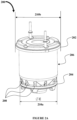
- FIG. 2A is front perspective view of the silent block bushing 200
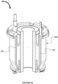
- Figure 2B is partial cutaway view of the silent block bushing 200, as the embodiment shown in Figure 2A of the present disclosure.
- the silent block bushing 200 comprises two flanges 202 and 204 positioned at opposing ends of a plastic outer tube 206, where the diameter 210a of the bottom flange 204 is less than the diameter 210b of the top flange 202.
- the flanges 202 and 204 are used for limiting axial displacement of the silent block bushing 200.
- a set of ribs 208 are positioned on the bottom flange 204, which are configured to avoid deformation of the silent block bushing 200 during assembly, and provide a control over cylindricity for consistency during pushing in/pushing out load.
- the cylindricity is further controlled based on the number of ribs 208 that are positioned on the flange 204, which also provides same stiffness on the top flange 202 and the bottom flange 204.
- the thickness 212 of the plastic outer tube 206 is varied to provide control over cylindricity and consistency in pushing in/pushing out a load.
- This variable thickness 212 of the plastic outer tube 206 also contributes to reduce cylindricity.
- the silent block bushing 200 is designed to overcome non cylindricity issue.
- the top flange 202, the bottom flange 204, and the ribs 208 provide equal stiffness in both flanges 202 and 204, which contributes to reduce cylindricity.
- the design of the bottom flange 204 also recompenses for any axial directional limitation as well as good for assembly.
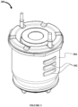
- Figure 3 is a front perspective view of another embodiment of the silent block bushing 300, as the embodiment of the present disclosure. As shown in figure 3 , a set of ribs 302 are also positioned in the middle of the plastic outer tube 304 to provide an increased control over cylindricity and consistency in pushing in/pushing out load.
Landscapes
- Engineering & Computer Science (AREA)
- General Engineering & Computer Science (AREA)
- Mechanical Engineering (AREA)
- Springs (AREA)
- Vibration Prevention Devices (AREA)
Claims (6)
- Geräuscharme Blockbuchse (200), umfassend:wenigstens zwei Flansche, umfassend einen Oberflansch (202) und einen Unterflansch (204) welche an zwei gegenüberliegenden Enden eines Außenrohrs (206) positioniert sind, wobei die Flansche (202, 204) eine axiale Beweglichkeit der geräuscharmen Blockbuchse (200) begrenzen,gekennzeichnet durcheinen Satz Rippen (208) welche auf dem Unterflansch (204) positioniert sind, um eine Deformation der geräuscharmen Blockbuchse (200) während der Montage zu verhindern, und, um eine Kontrolle der Zylindrizität für die Konsistenz beim Einschieben und Ausschieben einer Last zu ermöglichen.
- Geräuscharme Blockbuchse nach Anspruch 1,
wobei der Durchmesser des Unterflansches (204) geringer ist, als der Durchmesser des Oberflansches (202). - Geräuscharme Blockbuchse nach Anspruch 1,
wobei die Zylindrizität ferner basierend auf einer Anzahl der Rippen (208), welche auf dem Unterflansch (204) positioniert sind, kontrolliert wird, und wobei die Rippen (208) dem Oberflansch (202) und dem Unterflansch (204) die gleiche Steifigkeit aufprägen. - Geräuscharme Blockbuchse nach Anspruch 1,
wobei das Außenrohr (206) aus Kunststoff gefertigt ist und seine Dicke variiert wird, um die Zylindrizität zu reduzieren und Konsistenz beim Einschieben und Ausschieben der Last bereitzustellen. - Geräuscharme Blockbuchse nach Anspruch 1,
wobei der Oberflansch (202), der Unterflansch (204) und die Rippen (208) sowohl im oberen als auch im unteren Flansch (202, 204) für die gleiche Steifigkeit sorgen, was die Zylindrizität verringert, und wobei der untere Flansch (204) die axiale Richtungsbegrenzung ausgleicht. - Geräuscharme Blockbuchse nach Anspruch 1, ferner umfassend einen Satz Rippen (302), welche in der Mitte des Kunststoffaußenrohrs (206) positioniert sind, um eine erhöhte Kontrolle der Zylindrizität und Konsistenz beim Einschieben und Ausschieben der Last bereitzustellen.
Applications Claiming Priority (1)
| Application Number | Priority Date | Filing Date | Title |
|---|---|---|---|
| IN201921051330 | 2019-12-11 |
Publications (3)
| Publication Number | Publication Date |
|---|---|
| EP3875799A1 EP3875799A1 (de) | 2021-09-08 |
| EP3875799C0 EP3875799C0 (de) | 2023-09-06 |
| EP3875799B1 true EP3875799B1 (de) | 2023-09-06 |
Family
ID=73834250
Family Applications (1)
| Application Number | Title | Priority Date | Filing Date |
|---|---|---|---|
| EP20213380.7A Active EP3875799B1 (de) | 2019-12-11 | 2020-12-11 | Geräuscharme blockbuchse |
Country Status (2)
| Country | Link |
|---|---|
| EP (1) | EP3875799B1 (de) |
| JP (1) | JP7613902B2 (de) |
Family Cites Families (4)
| Publication number | Priority date | Publication date | Assignee | Title |
|---|---|---|---|---|
| DE102010018536A1 (de) * | 2010-04-28 | 2011-11-03 | Trelleborg Automotive Germany Gmbh | Elastische Lagerbuchsenanordnung, elastisches Lager und Verfahren zur Herstellung der elastischen Lagerbuchsenanordnung |
| US10422372B2 (en) * | 2017-10-27 | 2019-09-24 | Mf Ip Holding, Llc | Rotatable bushing |
| CN208686861U (zh) * | 2018-08-30 | 2019-04-02 | 上海众力投资发展有限公司 | 一种衬套产品结构 |
| CN110360255A (zh) * | 2019-07-16 | 2019-10-22 | 重庆恒伟林汽车零部件有限公司 | 一种适用于轻型汽车副车架的橡胶衬套 |
-
2020
- 2020-12-10 JP JP2020205334A patent/JP7613902B2/ja active Active
- 2020-12-11 EP EP20213380.7A patent/EP3875799B1/de active Active
Also Published As
| Publication number | Publication date |
|---|---|
| EP3875799A1 (de) | 2021-09-08 |
| JP7613902B2 (ja) | 2025-01-15 |
| EP3875799C0 (de) | 2023-09-06 |
| JP2021092320A (ja) | 2021-06-17 |
Similar Documents
| Publication | Publication Date | Title |
|---|---|---|
| US8579510B2 (en) | Rotatable bar pin bushing assembly | |
| US10704637B2 (en) | Bar pin bushing for vehicle suspension | |
| US7357379B2 (en) | Vibration isolating bushing | |
| US20050254888A1 (en) | Torque rod and method of producing the same | |
| US20090202184A1 (en) | Bush bearing with reduced installation space | |
| US10309477B2 (en) | Tubular vibration-damping device having bracket | |
| WO2012056635A1 (ja) | タンク用ゴムクッション | |
| US20060290040A1 (en) | Bush bearing with a radial and/or an axial limit stop and method for producing an axial limit stop in a bush bearing | |
| CN108223643A (zh) | 管状减振装置 | |
| EP3875799B1 (de) | Geräuscharme blockbuchse | |
| CN106476559B (zh) | 横向稳定组件 | |
| US9751376B2 (en) | Bushing having rotatable inner elements and stabilizer bar assembly having the same | |
| GB2534240A (en) | Bushing, in particular for a vehicle | |
| EP0072666A1 (de) | Lagerbuchse | |
| US20040017034A1 (en) | Vibration isolating bushing | |
| BR102014023604B1 (pt) | haste de eixo, montagem de haste de eixo, método de formar uma haste de eixo | |
| DE102014118502A1 (de) | Hydrolager | |
| KR102551641B1 (ko) | 차량용 다이나믹 댐퍼 | |
| US20150239505A1 (en) | Chassis mount structure | |
| US10995792B1 (en) | Self-retaining concentric bushing assembly | |
| KR101575530B1 (ko) | Ctba용 트레일링암 부시와 이를 적용한 차량용 ctba | |
| KR102563489B1 (ko) | 양단 버링 암 어셈블리 | |
| DE102004014328A1 (de) | Hydraulisch dämpfendes Gummilager | |
| JPH1047433A (ja) | サスペンション用ブッシュ | |
| CN205273079U (zh) | Ctba用纵臂衬套及适用该衬套的车辆用ctba |
Legal Events
| Date | Code | Title | Description |
|---|---|---|---|
| PUAI | Public reference made under article 153(3) epc to a published international application that has entered the european phase |
Free format text: ORIGINAL CODE: 0009012 |
|
| STAA | Information on the status of an ep patent application or granted ep patent |
Free format text: STATUS: THE APPLICATION HAS BEEN PUBLISHED |
|
| AK | Designated contracting states |
Kind code of ref document: A1 Designated state(s): AL AT BE BG CH CY CZ DE DK EE ES FI FR GB GR HR HU IE IS IT LI LT LU LV MC MK MT NL NO PL PT RO RS SE SI SK SM TR |
|
| STAA | Information on the status of an ep patent application or granted ep patent |
Free format text: STATUS: REQUEST FOR EXAMINATION WAS MADE |
|
| 17P | Request for examination filed |
Effective date: 20220308 |
|
| RBV | Designated contracting states (corrected) |
Designated state(s): AL AT BE BG CH CY CZ DE DK EE ES FI FR GB GR HR HU IE IS IT LI LT LU LV MC MK MT NL NO PL PT RO RS SE SI SK SM TR |
|
| GRAP | Despatch of communication of intention to grant a patent |
Free format text: ORIGINAL CODE: EPIDOSNIGR1 |
|
| STAA | Information on the status of an ep patent application or granted ep patent |
Free format text: STATUS: GRANT OF PATENT IS INTENDED |
|
| INTG | Intention to grant announced |
Effective date: 20230331 |
|
| GRAS | Grant fee paid |
Free format text: ORIGINAL CODE: EPIDOSNIGR3 |
|
| GRAA | (expected) grant |
Free format text: ORIGINAL CODE: 0009210 |
|
| STAA | Information on the status of an ep patent application or granted ep patent |
Free format text: STATUS: THE PATENT HAS BEEN GRANTED |
|
| RAP3 | Party data changed (applicant data changed or rights of an application transferred) |
Owner name: SUJAN CONTITECH AVS PVT. LTD. |
|
| AK | Designated contracting states |
Kind code of ref document: B1 Designated state(s): AL AT BE BG CH CY CZ DE DK EE ES FI FR GB GR HR HU IE IS IT LI LT LU LV MC MK MT NL NO PL PT RO RS SE SI SK SM TR |
|
| REG | Reference to a national code |
Ref country code: GB Ref legal event code: FG4D |
|
| REG | Reference to a national code |
Ref country code: CH Ref legal event code: EP |
|
| REG | Reference to a national code |
Ref country code: IE Ref legal event code: FG4D |
|
| REG | Reference to a national code |
Ref country code: DE Ref legal event code: R096 Ref document number: 602020017158 Country of ref document: DE |
|
| U01 | Request for unitary effect filed |
Effective date: 20230912 |
|
| U07 | Unitary effect registered |
Designated state(s): AT BE BG DE DK EE FI FR IT LT LU LV MT NL PT SE SI Effective date: 20230920 |
|
| U20 | Renewal fee for the european patent with unitary effect paid |
Year of fee payment: 4 Effective date: 20231211 |
|
| PG25 | Lapsed in a contracting state [announced via postgrant information from national office to epo] |
Ref country code: GR Free format text: LAPSE BECAUSE OF FAILURE TO SUBMIT A TRANSLATION OF THE DESCRIPTION OR TO PAY THE FEE WITHIN THE PRESCRIBED TIME-LIMIT Effective date: 20231207 |
|
| PG25 | Lapsed in a contracting state [announced via postgrant information from national office to epo] |
Ref country code: RS Free format text: LAPSE BECAUSE OF FAILURE TO SUBMIT A TRANSLATION OF THE DESCRIPTION OR TO PAY THE FEE WITHIN THE PRESCRIBED TIME-LIMIT Effective date: 20230906 Ref country code: NO Free format text: LAPSE BECAUSE OF FAILURE TO SUBMIT A TRANSLATION OF THE DESCRIPTION OR TO PAY THE FEE WITHIN THE PRESCRIBED TIME-LIMIT Effective date: 20231206 Ref country code: HR Free format text: LAPSE BECAUSE OF FAILURE TO SUBMIT A TRANSLATION OF THE DESCRIPTION OR TO PAY THE FEE WITHIN THE PRESCRIBED TIME-LIMIT Effective date: 20230906 Ref country code: GR Free format text: LAPSE BECAUSE OF FAILURE TO SUBMIT A TRANSLATION OF THE DESCRIPTION OR TO PAY THE FEE WITHIN THE PRESCRIBED TIME-LIMIT Effective date: 20231207 |
|
| PG25 | Lapsed in a contracting state [announced via postgrant information from national office to epo] |
Ref country code: IS Free format text: LAPSE BECAUSE OF FAILURE TO SUBMIT A TRANSLATION OF THE DESCRIPTION OR TO PAY THE FEE WITHIN THE PRESCRIBED TIME-LIMIT Effective date: 20240106 |
|
| PG25 | Lapsed in a contracting state [announced via postgrant information from national office to epo] |
Ref country code: ES Free format text: LAPSE BECAUSE OF FAILURE TO SUBMIT A TRANSLATION OF THE DESCRIPTION OR TO PAY THE FEE WITHIN THE PRESCRIBED TIME-LIMIT Effective date: 20230906 |
|
| PG25 | Lapsed in a contracting state [announced via postgrant information from national office to epo] |
Ref country code: SM Free format text: LAPSE BECAUSE OF FAILURE TO SUBMIT A TRANSLATION OF THE DESCRIPTION OR TO PAY THE FEE WITHIN THE PRESCRIBED TIME-LIMIT Effective date: 20230906 Ref country code: RO Free format text: LAPSE BECAUSE OF FAILURE TO SUBMIT A TRANSLATION OF THE DESCRIPTION OR TO PAY THE FEE WITHIN THE PRESCRIBED TIME-LIMIT Effective date: 20230906 Ref country code: IS Free format text: LAPSE BECAUSE OF FAILURE TO SUBMIT A TRANSLATION OF THE DESCRIPTION OR TO PAY THE FEE WITHIN THE PRESCRIBED TIME-LIMIT Effective date: 20240106 Ref country code: ES Free format text: LAPSE BECAUSE OF FAILURE TO SUBMIT A TRANSLATION OF THE DESCRIPTION OR TO PAY THE FEE WITHIN THE PRESCRIBED TIME-LIMIT Effective date: 20230906 Ref country code: CZ Free format text: LAPSE BECAUSE OF FAILURE TO SUBMIT A TRANSLATION OF THE DESCRIPTION OR TO PAY THE FEE WITHIN THE PRESCRIBED TIME-LIMIT Effective date: 20230906 Ref country code: SK Free format text: LAPSE BECAUSE OF FAILURE TO SUBMIT A TRANSLATION OF THE DESCRIPTION OR TO PAY THE FEE WITHIN THE PRESCRIBED TIME-LIMIT Effective date: 20230906 |
|
| PG25 | Lapsed in a contracting state [announced via postgrant information from national office to epo] |
Ref country code: PL Free format text: LAPSE BECAUSE OF FAILURE TO SUBMIT A TRANSLATION OF THE DESCRIPTION OR TO PAY THE FEE WITHIN THE PRESCRIBED TIME-LIMIT Effective date: 20230906 |
|
| REG | Reference to a national code |
Ref country code: DE Ref legal event code: R097 Ref document number: 602020017158 Country of ref document: DE |
|
| PLBE | No opposition filed within time limit |
Free format text: ORIGINAL CODE: 0009261 |
|
| STAA | Information on the status of an ep patent application or granted ep patent |
Free format text: STATUS: NO OPPOSITION FILED WITHIN TIME LIMIT |
|
| REG | Reference to a national code |
Ref country code: CH Ref legal event code: PL |
|
| 26N | No opposition filed |
Effective date: 20240607 |
|
| PG25 | Lapsed in a contracting state [announced via postgrant information from national office to epo] |
Ref country code: MC Free format text: LAPSE BECAUSE OF FAILURE TO SUBMIT A TRANSLATION OF THE DESCRIPTION OR TO PAY THE FEE WITHIN THE PRESCRIBED TIME-LIMIT Effective date: 20230906 |
|
| PG25 | Lapsed in a contracting state [announced via postgrant information from national office to epo] |
Ref country code: MC Free format text: LAPSE BECAUSE OF FAILURE TO SUBMIT A TRANSLATION OF THE DESCRIPTION OR TO PAY THE FEE WITHIN THE PRESCRIBED TIME-LIMIT Effective date: 20230906 |
|
| REG | Reference to a national code |
Ref country code: IE Ref legal event code: MM4A |
|
| PG25 | Lapsed in a contracting state [announced via postgrant information from national office to epo] |
Ref country code: IE Free format text: LAPSE BECAUSE OF NON-PAYMENT OF DUE FEES Effective date: 20231211 |
|
| PG25 | Lapsed in a contracting state [announced via postgrant information from national office to epo] |
Ref country code: CH Free format text: LAPSE BECAUSE OF NON-PAYMENT OF DUE FEES Effective date: 20231231 |
|
| PG25 | Lapsed in a contracting state [announced via postgrant information from national office to epo] |
Ref country code: IE Free format text: LAPSE BECAUSE OF NON-PAYMENT OF DUE FEES Effective date: 20231211 Ref country code: CH Free format text: LAPSE BECAUSE OF NON-PAYMENT OF DUE FEES Effective date: 20231231 |
|
| U20 | Renewal fee for the european patent with unitary effect paid |
Year of fee payment: 5 Effective date: 20241212 |
|
| PG25 | Lapsed in a contracting state [announced via postgrant information from national office to epo] |
Ref country code: CY Free format text: LAPSE BECAUSE OF FAILURE TO SUBMIT A TRANSLATION OF THE DESCRIPTION OR TO PAY THE FEE WITHIN THE PRESCRIBED TIME-LIMIT; INVALID AB INITIO Effective date: 20201211 |
|
| PG25 | Lapsed in a contracting state [announced via postgrant information from national office to epo] |
Ref country code: HU Free format text: LAPSE BECAUSE OF FAILURE TO SUBMIT A TRANSLATION OF THE DESCRIPTION OR TO PAY THE FEE WITHIN THE PRESCRIBED TIME-LIMIT; INVALID AB INITIO Effective date: 20201211 |
|
| GBPC | Gb: european patent ceased through non-payment of renewal fee |
Effective date: 20241211 |
|
| PG25 | Lapsed in a contracting state [announced via postgrant information from national office to epo] |
Ref country code: GB Free format text: LAPSE BECAUSE OF NON-PAYMENT OF DUE FEES Effective date: 20241211 |
|
| PG25 | Lapsed in a contracting state [announced via postgrant information from national office to epo] |
Ref country code: TR Free format text: LAPSE BECAUSE OF FAILURE TO SUBMIT A TRANSLATION OF THE DESCRIPTION OR TO PAY THE FEE WITHIN THE PRESCRIBED TIME-LIMIT Effective date: 20230906 |
|
| U20 | Renewal fee for the european patent with unitary effect paid |
Year of fee payment: 6 Effective date: 20251211 |