EP3875752A1 - Method and device for controlling a wind turbine to reduce noise - Google Patents
Method and device for controlling a wind turbine to reduce noise Download PDFInfo
- Publication number
- EP3875752A1 EP3875752A1 EP20161223.1A EP20161223A EP3875752A1 EP 3875752 A1 EP3875752 A1 EP 3875752A1 EP 20161223 A EP20161223 A EP 20161223A EP 3875752 A1 EP3875752 A1 EP 3875752A1
- Authority
- EP
- European Patent Office
- Prior art keywords
- add
- wind turbine
- blade
- control device
- noise level
- Prior art date
- Legal status (The legal status is an assumption and is not a legal conclusion. Google has not performed a legal analysis and makes no representation as to the accuracy of the status listed.)
- Withdrawn
Links
- 238000000034 method Methods 0.000 title claims abstract description 22
- 230000004913 activation Effects 0.000 claims description 12
- 238000004519 manufacturing process Methods 0.000 claims description 7
- 238000010248 power generation Methods 0.000 claims description 5
- 230000000694 effects Effects 0.000 description 6
- 230000005534 acoustic noise Effects 0.000 description 3
- 230000009286 beneficial effect Effects 0.000 description 1
- 230000001419 dependent effect Effects 0.000 description 1
- 238000005457 optimization Methods 0.000 description 1
Images


Classifications
-
- F—MECHANICAL ENGINEERING; LIGHTING; HEATING; WEAPONS; BLASTING
- F03—MACHINES OR ENGINES FOR LIQUIDS; WIND, SPRING, OR WEIGHT MOTORS; PRODUCING MECHANICAL POWER OR A REACTIVE PROPULSIVE THRUST, NOT OTHERWISE PROVIDED FOR
- F03D—WIND MOTORS
- F03D7/00—Controlling wind motors
- F03D7/02—Controlling wind motors the wind motors having rotation axis substantially parallel to the air flow entering the rotor
- F03D7/0296—Controlling wind motors the wind motors having rotation axis substantially parallel to the air flow entering the rotor to prevent, counteract or reduce noise emissions
-
- F—MECHANICAL ENGINEERING; LIGHTING; HEATING; WEAPONS; BLASTING
- F03—MACHINES OR ENGINES FOR LIQUIDS; WIND, SPRING, OR WEIGHT MOTORS; PRODUCING MECHANICAL POWER OR A REACTIVE PROPULSIVE THRUST, NOT OTHERWISE PROVIDED FOR
- F03D—WIND MOTORS
- F03D7/00—Controlling wind motors
- F03D7/02—Controlling wind motors the wind motors having rotation axis substantially parallel to the air flow entering the rotor
- F03D7/022—Adjusting aerodynamic properties of the blades
- F03D7/0232—Adjusting aerodynamic properties of the blades with flaps or slats
-
- F—MECHANICAL ENGINEERING; LIGHTING; HEATING; WEAPONS; BLASTING
- F05—INDEXING SCHEMES RELATING TO ENGINES OR PUMPS IN VARIOUS SUBCLASSES OF CLASSES F01-F04
- F05B—INDEXING SCHEME RELATING TO WIND, SPRING, WEIGHT, INERTIA OR LIKE MOTORS, TO MACHINES OR ENGINES FOR LIQUIDS COVERED BY SUBCLASSES F03B, F03D AND F03G
- F05B2240/00—Components
- F05B2240/20—Rotors
- F05B2240/30—Characteristics of rotor blades, i.e. of any element transforming dynamic fluid energy to or from rotational energy and being attached to a rotor
- F05B2240/305—Flaps, slats or spoilers
- F05B2240/3052—Flaps, slats or spoilers adjustable
-
- F—MECHANICAL ENGINEERING; LIGHTING; HEATING; WEAPONS; BLASTING
- F05—INDEXING SCHEMES RELATING TO ENGINES OR PUMPS IN VARIOUS SUBCLASSES OF CLASSES F01-F04
- F05B—INDEXING SCHEME RELATING TO WIND, SPRING, WEIGHT, INERTIA OR LIKE MOTORS, TO MACHINES OR ENGINES FOR LIQUIDS COVERED BY SUBCLASSES F03B, F03D AND F03G
- F05B2260/00—Function
- F05B2260/96—Preventing, counteracting or reducing vibration or noise
-
- F—MECHANICAL ENGINEERING; LIGHTING; HEATING; WEAPONS; BLASTING
- F05—INDEXING SCHEMES RELATING TO ENGINES OR PUMPS IN VARIOUS SUBCLASSES OF CLASSES F01-F04
- F05B—INDEXING SCHEME RELATING TO WIND, SPRING, WEIGHT, INERTIA OR LIKE MOTORS, TO MACHINES OR ENGINES FOR LIQUIDS COVERED BY SUBCLASSES F03B, F03D AND F03G
- F05B2270/00—Control
- F05B2270/30—Control parameters, e.g. input parameters
- F05B2270/333—Noise or sound levels
-
- Y—GENERAL TAGGING OF NEW TECHNOLOGICAL DEVELOPMENTS; GENERAL TAGGING OF CROSS-SECTIONAL TECHNOLOGIES SPANNING OVER SEVERAL SECTIONS OF THE IPC; TECHNICAL SUBJECTS COVERED BY FORMER USPC CROSS-REFERENCE ART COLLECTIONS [XRACs] AND DIGESTS
- Y02—TECHNOLOGIES OR APPLICATIONS FOR MITIGATION OR ADAPTATION AGAINST CLIMATE CHANGE
- Y02E—REDUCTION OF GREENHOUSE GAS [GHG] EMISSIONS, RELATED TO ENERGY GENERATION, TRANSMISSION OR DISTRIBUTION
- Y02E10/00—Energy generation through renewable energy sources
- Y02E10/70—Wind energy
- Y02E10/72—Wind turbines with rotation axis in wind direction
Definitions
- the present invention relates to a method of controlling a wind turbine and to a control device for controlling a wind turbine in order to reduce an actual acoustic noise level caused by the operation of the wind turbine.
- Wind turbines are often built on sites that require a maximum allowed acoustic noise level.
- the allowed noise level may change according to the time of day, the day of the week, the wind speed, the wind direction, etc.
- Add-on members or flaps as aerodynamic devices such as so-called trim stall devices may increase the noise level when they are utilized.
- Such add-on members can be arranged in an array of many segments per wind turbine blade, each of which can stall a part of the blade. This particularly applies to trim stall devices as stalled segments of the blade typically generate more noise than non-stalled segments. If no control is imposed on the utilization of the add-on members, the resulting noise level may then exceed the allowed acoustic noise level specially during periods where stricter noise requirements are required.
- a method of controlling a wind turbine comprises a hub having at least one blade with at least one an add-on member which is actuated to alter aerodynamic properties of the blade.
- the method comprises a step of acquiring a target noise level, for example in the environment of the wind turbine, and a step of controlling the at least one add-on member of the blade such that an actual noise level caused by the operation of the wind turbine is equal to or below the target noise level.
- the utilization of the add-on member is limited based on the present noise requirements. Compared with conventional noise reduction measures, an optimal operation of the wind turbine in terms of power production can be achieved because it is not necessary to reduce the nominal rotor speed or the output power. Also the pitch angle or the tip speed do not need to be changed.
- the at least one add-on member is controlled such that a power generation of the wind turbine is maximum, while the actual noise level caused by the operation of the wind turbine is maintained equal to or below the target noise level. It is the aim to limit the utilization of the add-on member to reach the target noise level and at the same time not to limit the utilization of the add-on member more than necessary in order to optimize the output power of the wind turbine. Generally, the utilization of the add-on members may be beneficial for power optimization or load reduction.
- the wind turbine in particular the blade, comprises a plurality of the add-on members, and the plurality of add-on members is controlled by limiting a maximum number of add-on members of the plurality of add-on members, which are allowed to be simultaneously actuated to their active positions.
- active position or “activation level” can either refer to a maximum extended position or to a position between the maximum extended position and a fully retracted position.
- active position can in turn refer to the fully retracted position.
- the at least one add-on member is configured to be continuously moved between a fully retracted position and a fully extended position, and the at least one add-on member is controlled by limiting a maximum allowable position, that is the active position or an activation level, between the fully retracted position and the fully extended position.
- a maximum allowable position that is the active position or an activation level
- the present invention is also applicable to add-on members such as trailing flaps, where the active position or the activation level may be continuous, e.g. with a deflection between a maximum activation or deflection level and a minimum activation or deflection level.
- a limitation may mean that only a limited activation range or deflection is allowed.
- the method further comprises a step of creating a noise model of the wind turbine or a lookup table, which describe the actual noise level as a function of an activation level of the at least one add-on member and of at least one operating parameter of the wind turbine, and the controlling of the at least one add-on member of the blade is carried out by use of the noise model or the lookup table.
- the at least one operating parameter of the wind turbine comprises at least one of a rotational speed of the hub, a power production of the wind turbine, a pitch angle of the at least one blade, and a wind speed in an environment of the wind turbine. Also other estimated parameters could be used as an input for the noise model or lookup table.
- the noise model or the lookup table describe the actual noise level further as a function of a position of the at least one add-on member at the blade.
- the at least one blade comprises at least one first add-on member and at least one second add-on member, wherein the at least one first add-on member is closer to an inboard portion of the blade than the at least one second add-on member.
- the term "inboard” can refer to a position which is closer to the hub-side of the blade, whereas the term “outboard” can refer to a position which is closer to the blade's tip-side.
- the first add-on member is controlled in a different manner compared with the second add-on member, in particular the first add-on member is controlled to achieve a first noise reduction level, and the second add-on member is controlled to achieve a second noise reduction level.
- the noise reduction level can refer to an amount by which the noise is reduced.
- the first noise reduction level can be lower than the second noise reduction level.
- the limitation of the add-on member utilization is made based on the location of the add-on members.
- the actual noise level is measured by a noise detecting device.
- a control device for controlling a wind turbine comprises a hub having at least one blade with at least one an add-on member which is actuated to alter aerodynamic properties of the blade.
- the control device is configured to acquire a target noise level, for example in the environment of the wind turbine, and the control device is configured to control the at least one add-on member of the blade such that an actual noise level caused by the operation of the wind turbine is equal to or below the target noise level.
- the control device is preferably configured to control the at least one add-on member such that a power generation of the wind turbine is maximum, while the actual noise level caused by the operation of the wind turbine is maintained equal to or below the target noise level.
- the wind turbine in particular the blade, comprises a plurality of the add-on members
- the control device is configured to control the plurality of add-on members by limiting a maximum number of add-on members of the plurality of add-on members, which are allowed to be simultaneously actuated to their active positions.
- the at least one add-on member is configured to be continuously moved between a fully retracted position and a fully extended position
- the control device is configured to control the at least one add-on member by limiting a maximum allowable position between the fully retracted position and the fully extended position
- control device is configured to control the at least one add-on member by use of a noise model of the wind turbine or a lookup table, which describe the actual noise level as a function of an activation level of the at least one add-on member and at least one operating parameter of the wind turbine, wherein the at least one operating parameter of the wind turbine preferably comprises at least one of a rotational speed of the hub, a power production of the wind turbine, a pitch angle of the at least one blade, and a wind speed in an environment of the wind turbine.
- control device is configured to receive the actual noise level from a noise detecting device which can comprise a microphone or a vibration detecting device.
- a noise detecting device which can comprise a microphone or a vibration detecting device.
- the microphone and the vibration detecting device can be mounted to the blade, the hub, a nacelle or a tower of the wind turbine.
- control device is an external device, for example a remote station, apart from the wind turbine, wherein the control device is configured to send a control signal to the wind turbine for controlling the at least one add-on member.
- Fig. 1 shows a wind turbine 1.
- the wind turbine 1 comprises a nacelle 3 and a tower 2.
- the nacelle 3 is mounted at the top of the tower 2.
- the nacelle 3 is mounted rotatable with regard to the tower 2 by means of a yaw bearing.
- the axis of rotation of the nacelle 3 with regard to the tower 2 is referred to as the yaw axis.
- the wind turbine 1 also comprises a hub 4 with three rotor blades 6 (of which two rotor blades 6 are depicted in Fig. 1 ).
- the hub 4 is mounted rotatable with regard to the nacelle 3 by means of a main bearing 7.
- the hub 4 is mounted rotatable about a rotor axis of rotation 8.
- the wind turbine 1 furthermore comprises a generator 5.
- the generator 5 in turn comprises a rotor 10 connecting the generator 5 with the hub 4.
- the hub 4 is connected directly to the generator 5, thus the wind turbine 1 is referred to as a gearless, direct-driven wind turbine.
- Such a generator 5 is referred as direct drive generator 5.
- the hub 4 may also be connected to the generator 5 via a gear box.
- This type of wind turbine 1 is referred to as a geared wind turbine.
- the present invention is suitable for both types of wind turbines 1.
- the generator 5 is accommodated within the nacelle 3.
- the generator 5 is arranged and prepared for converting the rotational energy from the hub 4 into electrical energy in the shape of an AC power.
- Fig. 2 shows a perspective view of a blade 6 having add-on members 17 according to an embodiment.
- Reference sign 9 designates an inboard portion of the blade 6, and reference sign 10 designates an outboard portion of the blade 6.
- the blade 6 comprises at least one add-on member 17, for example two add-on members 17.
- the add-on members 17 can be placed at any part along a longitudinal direction of the blade 6.
- two add-on members 17 are formed as hinged flaps provided at a trailing edge of the blade 6. Strictly speaking, one add-on member 17 is provided at the inboard portion 9, and another add-on member 17 is provided at the outboard portion 10.
- Fig. 1 shows a perspective view of a blade 6 having add-on members 17 according to an embodiment.
- Reference sign 9 designates an inboard portion of the blade 6
- reference sign 10 designates an outboard portion of the blade 6.
- the blade 6 comprises at least one add-on member 17, for example two add-on members 17.
- the add-on members 17 can be placed at any part along
- the outboard add-on member 17 is in a retracted position and thus deactivated, while the inboard add-on member 17 is in an extended position and thus activated.
- the add-on member 17 could also be moved to any intermediate position between the fully extended position and the fully retracted position. Any movement of the add-on members 17 can be carried out by one or more trim actuators (not shown).
- trim actuators not shown.
- the add-on member 17 When the add-on member 17 is activated, it changes or modifies an aerodynamic surface or shape of the blade 6, thereby altering lift and/or drag coefficients of the blade 6 during operation. In general, an aerodynamic shape of the blade 6 can be modified by altering a position of the add-on members 17.
- Figures 3 and 4 show cross-sectional views of a blade 6 having an add-on member 17 according to an embodiment.
- the add-on member 17 is designed as a spoiler.
- the add-on member 17 is here arranged near the leading edge of the blade 6 but can also be arranged near the trailing edge of the blade 6.
- the add-on member 17 is accommodated in a recess 16 in the blade 6 and can turn about a hinge 18, for example by activation of a trim actuator (not shown).
- the add-on member 17 is shown in a fully retracted position, where the add-on member 17 is deactivated and no spoiler effect and no stall are desired.
- the add-on member 17 is in a fully extended position and thus activated.
- the add-on member 17 is turned to a maximum position, for example by the trim actuator, so that the stalling effect is maximum.
- the add-on member 17 could also be moved to any intermediate position between the fully extended position and the fully retracted position. Any movement of the add-on members 17 can be carried out by the trim actuator.
- the add-on member 17 is not necessarily to be formed as a spoiler.
- the add-on member 17 can have any other configuration which is able to alter the aerodynamic properties of the blade 6.
- a plurality of the add-on members 17 of the embodiments in Figures 2, 3 and 4 can be provided in an array on the same blade 6 so that the add-on members 17 can be referred to as segmented add-on members 17 which can be actuated independently from each other.
- the stalling effect at the blade 6 can be controlled by modifying the number of add-on members 17 which is moved to the extended position. It is possible to stop the add-on members 17 at only two end positions, namely at their fully retracted and extended positions. Alternatively, the stall effect can be fine-tuned by stopping the add-on members 17 at any intermediate position between the fully retracted and extended positions. This is particularly useful for add-on members 17 which are arranged at the trailing edge of the blade 6, i.e. so-called trailing flaps.
- Figures 5 and 6 show cross-sectional views of a blade 6 having an add-on member 17 according to an embodiment.
- the add-on members 17 of Figures 2, 3 and 4 use hinges by which the add-on members 17 are rotatably moved between the active and inactive positions.
- the blades 6 usually comprise quite long and flexible structures which can be deformed during normal operation. The deformation may cause clearances at the hinged add-on members 17 so that noise might occur.
- the embodiment of Figures 5 and 6 therefore uses an add-on member 17 at the trailing edge of the blade 6 which causes a continuous skin deflection of the blade 6.
- the add-on member 17 is formed as a shiftable or translatable extension of the trailing edge of the blade 6.
- the add-on member 17 in Fig. 6 is in an extended position and thus activated.
- the add-on member 17 could also be moved to any intermediate position between the fully extended position and the fully retracted position. Any movement of the add-on members 17 can be carried out by a trim actuator (not shown).
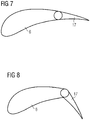
- Figures 7 and 8 show cross-sectional views of a blade 6 having an add-on member 17 according to an embodiment.
- the add-on member 17 in the embodiment of Figures 7 and 8 is arranged at the trailing edge of the blade 6 and causes a continuous skin deflection of the blade 6.
- the add-on member 17 is formed as a plain flap which rotates up and downwards on a hinge mounted at the front of the flap.
- the add-on member 17 in Fig. 7 is in a retracted position and thus deactivated, while the add-on member 17 in Fig. 8 is in an extended position and thus activated.
- the add-on member 17 could also be moved to any intermediate position between the fully extended position and the fully retracted position. Any movement of the add-on members 17 can be carried out by a trim actuator (not shown).
- add-on members 17 of the embodiments in Figures 2, 3 and 4 are referred to as segmented add-on members 17, the add-on members 17 in the embodiment of Figures 5 to 8 are not segmented and are usually continuously be actuated between its retracted and extended positions.
- All add-on members 17 can be modified compared to the described embodiments. Any add-on member 17 is appropriate for the present invention as long as it can actively be moved, rotated, shifted or translated within a cross-section of the blade 6.
- the add-on members 17 can be actuated by an actuator so that these add-on members 17 are referred as active add-on members 17. Contrary to this, the add-on members 17 can be actuated by the wind, by inertia forces and/or by centripetal forces so that these add-on members 17 are referred as passive add-on members 17. Both active and passive add-on members 17 are appropriate to realize the present invention.
- any add-on member 17 can be arranged at different locations at the blade 6, for example either at the inboard portion 9 of the blade 6 or at the outboard portion 10 of the blade 6.
- a single blade 6 can comprise at least one first add-on member 17 and at least one second add-on member 17, wherein the at least one first add-on member 17 is closer to the inboard portion 9 of the blade 6 than the at least one second add-on member 17. Consequently, the at least one second add-on member 17 is closer to the outboard portion 10 of the blade 6 than the at least one first add-on member 17.
- the second add-on member 17 generates more noise than the first add-on member 17 so that the first and second add-on members 17 can differently be controlled so as to achieve different noise reduction levels.
- a method of controlling the wind turbine 1 comprises a step of acquiring a target noise level, for example in the environment of the wind turbine 1, and a step of controlling the at least one add-on member 17 of the blade 2 such that an actual noise level caused by the operation of the wind turbine 1 is equal to or below the target noise level.
- the at least one add-on member 17 is preferably controlled such that a power generation of the wind turbine 1 is maximum, while the actual noise level caused by the operation of the wind turbine 1 is maintained equal to or below the target noise level.
- the wind turbine 1, in particular the blade 6, comprises a plurality of the add-on members 17, for example segmented add-on members 17, the plurality of add-on members 17 can be controlled by limiting a maximum number of add-on members 17 of the plurality of add-on members 17, which are allowed to be simultaneously actuated to their active positions.
- the at least one add-on member 17 is configured to be continuously moved between a fully retracted position and a fully extended position, the at least one add-on member 17 can be controlled by limiting a maximum allowable position between the fully retracted position and the fully extended position.
- a noise model of the wind turbine 1 or a lookup table can be created, which describe the actual noise level as a function of an activation level of the at least one add-on member 17 and of at least one operating parameter of the wind turbine 1.
- the controlling of the at least one add-on member 17 of the blade 2 is carried out by use of the noise model or the lookup table.
- the at least one operating parameter of the wind turbine 1 can comprises at least one of a rotational speed of the hub 4, a power production of the wind turbine 1, a pitch angle of the at least one blade 6, and a wind speed in the environment of the wind turbine 1.
- the noise model or the lookup table can further describe the actual noise level as a function of a position of the at least one add-on member 17 at the blade 6.
- the at least one blade 6 can comprises the at least one first add-on member 17 and the at least one second add-on member 17, wherein the at least one first add-on member 17 is closer to the inboard portion 9 of the blade 6 than the at least one second add-on member 17.
- the second add-on member 17 generates more noise than the first add-on member 17.
- the first add-on member 17 can be controlled in a different manner compared with the second add-on member 17, in particular the first add-on member 17 can be controlled to achieve a first noise reduction level, and the second add-on member 17 can be controlled to achieve a second noise reduction level.
- the noise reduction level means an amount by which the noise is reduced.
- the first noise reduction level can be lower than the second noise reduction level.
- the actual noise level can be measured by a noise detecting device.
- the noise detecting device can comprise at least one of a microphone and a vibration detector.
- the method is carried out by an external device apart from the wind turbine 1, wherein the external device is configured to send a control signal to the wind turbine 1 for controlling the at least one add-on member 17.
Abstract
It is described a method of controlling a wind turbine (1), wherein the wind turbine (1) comprises a hub (4) having at least one blade (6) with at least one an add-on member (17) which is actuated to alter aerodynamic properties of the blade (6). The method comprises a step of acquiring a target noise level, and a step of controlling the at least one add-on member (17) of the blade (2) such that an actual noise level caused by the operation of the wind turbine (1) is equal to or below the target noise level.
Description
- The present invention relates to a method of controlling a wind turbine and to a control device for controlling a wind turbine in order to reduce an actual acoustic noise level caused by the operation of the wind turbine.
- Wind turbines are often built on sites that require a maximum allowed acoustic noise level. The allowed noise level may change according to the time of day, the day of the week, the wind speed, the wind direction, etc. Add-on members or flaps as aerodynamic devices such as so-called trim stall devices may increase the noise level when they are utilized. Such add-on members can be arranged in an array of many segments per wind turbine blade, each of which can stall a part of the blade. This particularly applies to trim stall devices as stalled segments of the blade typically generate more noise than non-stalled segments. If no control is imposed on the utilization of the add-on members, the resulting noise level may then exceed the allowed acoustic noise level specially during periods where stricter noise requirements are required.
- Current solutions for noise curtailing turbines include steps of reducing a nominal rotor speed and/or an output power of the wind turbine. Also other parts of the wind turbines operation could be modified to reduce noise such as a pitch angle of a blade, a tip speed of the blade, etc. However, all these conventional measures reduce the performance, in particular the output power, for the wind turbines.
- There may be a need for a method of controlling a wind turbine and a control device for controlling a wind turbine, which can reduce the noise without unduly curtailing the wind turbine performance. This need may be met by the subject matters according to the independent claims. The present invention is further developed as set forth in the dependent claims.
- According to a first aspect of the invention, a method of controlling a wind turbine is provided. The wind turbine comprises a hub having at least one blade with at least one an add-on member which is actuated to alter aerodynamic properties of the blade. The method comprises a step of acquiring a target noise level, for example in the environment of the wind turbine, and a step of controlling the at least one add-on member of the blade such that an actual noise level caused by the operation of the wind turbine is equal to or below the target noise level. The utilization of the add-on member is limited based on the present noise requirements. Compared with conventional noise reduction measures, an optimal operation of the wind turbine in terms of power production can be achieved because it is not necessary to reduce the nominal rotor speed or the output power. Also the pitch angle or the tip speed do not need to be changed.
- In an embodiment, the at least one add-on member is controlled such that a power generation of the wind turbine is maximum, while the actual noise level caused by the operation of the wind turbine is maintained equal to or below the target noise level. It is the aim to limit the utilization of the add-on member to reach the target noise level and at the same time not to limit the utilization of the add-on member more than necessary in order to optimize the output power of the wind turbine. Generally, the utilization of the add-on members may be beneficial for power optimization or load reduction.
- In an embodiment, the wind turbine, in particular the blade, comprises a plurality of the add-on members, and the plurality of add-on members is controlled by limiting a maximum number of add-on members of the plurality of add-on members, which are allowed to be simultaneously actuated to their active positions. In the context of the present invention, the terms "active position" or "activation level" can either refer to a maximum extended position or to a position between the maximum extended position and a fully retracted position. The term "inactive position" can in turn refer to the fully retracted position.
- In an embodiment, the at least one add-on member is configured to be continuously moved between a fully retracted position and a fully extended position, and the at least one add-on member is controlled by limiting a maximum allowable position, that is the active position or an activation level, between the fully retracted position and the fully extended position. While many conventional add-on members have only two operating positions, that is a closed position with insignificant effect on the airflow over the blade profile, and an open position with significant effect on the air flow, the present invention is also applicable to add-on members such as trailing flaps, where the active position or the activation level may be continuous, e.g. with a deflection between a maximum activation or deflection level and a minimum activation or deflection level. In this case, a limitation may mean that only a limited activation range or deflection is allowed.
- In an embodiment, the method further comprises a step of creating a noise model of the wind turbine or a lookup table, which describe the actual noise level as a function of an activation level of the at least one add-on member and of at least one operating parameter of the wind turbine, and the controlling of the at least one add-on member of the blade is carried out by use of the noise model or the lookup table.
- Thereby, a maximum power production of the wind turbine can be calculated based on the current operating conditions and noise requirements. In an embodiment, the at least one operating parameter of the wind turbine comprises at least one of a rotational speed of the hub, a power production of the wind turbine, a pitch angle of the at least one blade, and a wind speed in an environment of the wind turbine. Also other estimated parameters could be used as an input for the noise model or lookup table.
- In an embodiment, the noise model or the lookup table describe the actual noise level further as a function of a position of the at least one add-on member at the blade.
- For example, in an embodiment, the at least one blade comprises at least one first add-on member and at least one second add-on member, wherein the at least one first add-on member is closer to an inboard portion of the blade than the at least one second add-on member. In the context of the present invention, the term "inboard" can refer to a position which is closer to the hub-side of the blade, whereas the term "outboard" can refer to a position which is closer to the blade's tip-side. The first add-on member is controlled in a different manner compared with the second add-on member, in particular the first add-on member is controlled to achieve a first noise reduction level, and the second add-on member is controlled to achieve a second noise reduction level. The noise reduction level can refer to an amount by which the noise is reduced. Preferably, as the outboard second add-on member usually generates more noise than the inboard first add-on member, the first noise reduction level can be lower than the second noise reduction level. Here, the limitation of the add-on member utilization is made based on the location of the add-on members.
- In an embodiment, the actual noise level is measured by a noise detecting device.
- According to a second aspect of the invention, a control device for controlling a wind turbine is provided. The wind turbine comprises a hub having at least one blade with at least one an add-on member which is actuated to alter aerodynamic properties of the blade. The control device is configured to acquire a target noise level, for example in the environment of the wind turbine, and the control device is configured to control the at least one add-on member of the blade such that an actual noise level caused by the operation of the wind turbine is equal to or below the target noise level. The control device is preferably configured to control the at least one add-on member such that a power generation of the wind turbine is maximum, while the actual noise level caused by the operation of the wind turbine is maintained equal to or below the target noise level.
- In an embodiment, the wind turbine, in particular the blade, comprises a plurality of the add-on members, and the control device is configured to control the plurality of add-on members by limiting a maximum number of add-on members of the plurality of add-on members, which are allowed to be simultaneously actuated to their active positions.
- In an embodiment, the at least one add-on member is configured to be continuously moved between a fully retracted position and a fully extended position, and the control device is configured to control the at least one add-on member by limiting a maximum allowable position between the fully retracted position and the fully extended position.
- In an embodiment, the control device is configured to control the at least one add-on member by use of a noise model of the wind turbine or a lookup table, which describe the actual noise level as a function of an activation level of the at least one add-on member and at least one operating parameter of the wind turbine, wherein the at least one operating parameter of the wind turbine preferably comprises at least one of a rotational speed of the hub, a power production of the wind turbine, a pitch angle of the at least one blade, and a wind speed in an environment of the wind turbine.
- In an embodiment, the control device is configured to receive the actual noise level from a noise detecting device which can comprise a microphone or a vibration detecting device. The microphone and the vibration detecting device can be mounted to the blade, the hub, a nacelle or a tower of the wind turbine.
- In an embodiment, the control device is an external device, for example a remote station, apart from the wind turbine, wherein the control device is configured to send a control signal to the wind turbine for controlling the at least one add-on member.
- It has to be noted that embodiments of the invention have been described with reference to different subject matters. In particular, some embodiments have been described with reference to apparatus type claims whereas other embodiments have been described with reference to method type claims. However, a person skilled in the art will gather from the above and the following description that, unless other notified, in addition to any combination of features belonging to one type of subject matter also any combination between features relating to different subject matters, in particular between features of the apparatus type claims and features of the method type claims is considered as to be disclosed with this application.
- The aspects defined above and further aspects of the present invention are apparent from the examples of embodiment to be described hereinafter and are explained with reference to the examples of embodiment. The invention will be described in more detail hereinafter with reference to examples of embodiment but to which the invention is not limited.
- Fig. 1
- shows a wind turbine and the different elements thereof;
- Fig. 2
- shows a perspective view of a blade having an add-on member according to an embodiment;
- Fig. 3
- shows a cross-sectional view of a blade having an add-on member according to an embodiment;
- Fig. 4
- shows a cross-sectional view of the blade of
Fig. 3 ; and - Fig. 5
- shows a cross-sectional view of a blade having an add-on member according to an embodiment;
- Fig. 6
- shows a cross-sectional view of the blade of
Fig. 5 ; - Fig. 7
- shows a cross-sectional view of a blade having an add-on member according to an embodiment;
- Fig. 8
- shows a cross-sectional view of the blade of
Fig. 7 . - The illustrations in the drawings are schematically. It is noted that in different figures, similar or identical elements are provided with the same reference signs.
-
Fig. 1 shows a wind turbine 1. The wind turbine 1 comprises anacelle 3 and atower 2. Thenacelle 3 is mounted at the top of thetower 2. Thenacelle 3 is mounted rotatable with regard to thetower 2 by means of a yaw bearing. The axis of rotation of thenacelle 3 with regard to thetower 2 is referred to as the yaw axis. - The wind turbine 1 also comprises a hub 4 with three rotor blades 6 (of which two
rotor blades 6 are depicted inFig. 1 ). The hub 4 is mounted rotatable with regard to thenacelle 3 by means of a main bearing 7. The hub 4 is mounted rotatable about a rotor axis ofrotation 8. - The wind turbine 1 furthermore comprises a
generator 5. Thegenerator 5 in turn comprises arotor 10 connecting thegenerator 5 with the hub 4. The hub 4 is connected directly to thegenerator 5, thus the wind turbine 1 is referred to as a gearless, direct-driven wind turbine. Such agenerator 5 is referred asdirect drive generator 5. As an alternative, the hub 4 may also be connected to thegenerator 5 via a gear box. This type of wind turbine 1 is referred to as a geared wind turbine. The present invention is suitable for both types of wind turbines 1. - The
generator 5 is accommodated within thenacelle 3. Thegenerator 5 is arranged and prepared for converting the rotational energy from the hub 4 into electrical energy in the shape of an AC power. -
Fig. 2 shows a perspective view of ablade 6 having add-onmembers 17 according to an embodiment.Reference sign 9 designates an inboard portion of theblade 6, andreference sign 10 designates an outboard portion of theblade 6. Theblade 6 comprises at least one add-onmember 17, for example two add-onmembers 17. The add-onmembers 17 can be placed at any part along a longitudinal direction of theblade 6. In this embodiment, two add-onmembers 17 are formed as hinged flaps provided at a trailing edge of theblade 6. Strictly speaking, one add-onmember 17 is provided at theinboard portion 9, and another add-onmember 17 is provided at theoutboard portion 10. InFig. 2 , the outboard add-onmember 17 is in a retracted position and thus deactivated, while the inboard add-onmember 17 is in an extended position and thus activated. However, the add-onmember 17 could also be moved to any intermediate position between the fully extended position and the fully retracted position. Any movement of the add-onmembers 17 can be carried out by one or more trim actuators (not shown). When the add-onmember 17 is activated, it changes or modifies an aerodynamic surface or shape of theblade 6, thereby altering lift and/or drag coefficients of theblade 6 during operation. In general, an aerodynamic shape of theblade 6 can be modified by altering a position of the add-onmembers 17. -
Figures 3 and 4 show cross-sectional views of ablade 6 having an add-onmember 17 according to an embodiment. The add-onmember 17 is designed as a spoiler. The add-onmember 17 is here arranged near the leading edge of theblade 6 but can also be arranged near the trailing edge of theblade 6. The add-onmember 17 is accommodated in arecess 16 in theblade 6 and can turn about ahinge 18, for example by activation of a trim actuator (not shown). InFig. 3 , the add-onmember 17 is shown in a fully retracted position, where the add-onmember 17 is deactivated and no spoiler effect and no stall are desired. InFig. 4 , the add-onmember 17 is in a fully extended position and thus activated. Strictly speaking, the add-onmember 17 is turned to a maximum position, for example by the trim actuator, so that the stalling effect is maximum. However, the add-onmember 17 could also be moved to any intermediate position between the fully extended position and the fully retracted position. Any movement of the add-onmembers 17 can be carried out by the trim actuator. - According to the present invention, the add-on
member 17 is not necessarily to be formed as a spoiler. The add-onmember 17 can have any other configuration which is able to alter the aerodynamic properties of theblade 6. - A plurality of the add-on
members 17 of the embodiments inFigures 2, 3 and 4 can be provided in an array on thesame blade 6 so that the add-onmembers 17 can be referred to as segmented add-onmembers 17 which can be actuated independently from each other. The stalling effect at theblade 6 can be controlled by modifying the number of add-onmembers 17 which is moved to the extended position. It is possible to stop the add-onmembers 17 at only two end positions, namely at their fully retracted and extended positions. Alternatively, the stall effect can be fine-tuned by stopping the add-onmembers 17 at any intermediate position between the fully retracted and extended positions. This is particularly useful for add-onmembers 17 which are arranged at the trailing edge of theblade 6, i.e. so-called trailing flaps. -
Figures 5 and 6 show cross-sectional views of ablade 6 having an add-onmember 17 according to an embodiment. As described before, the add-onmembers 17 ofFigures 2, 3 and 4 use hinges by which the add-onmembers 17 are rotatably moved between the active and inactive positions. However, theblades 6 usually comprise quite long and flexible structures which can be deformed during normal operation. The deformation may cause clearances at the hinged add-onmembers 17 so that noise might occur. The embodiment ofFigures 5 and 6 therefore uses an add-onmember 17 at the trailing edge of theblade 6 which causes a continuous skin deflection of theblade 6. In detail, the add-onmember 17 is formed as a shiftable or translatable extension of the trailing edge of theblade 6. The add-onmember 17 inFig. 5 is in a retracted position and thus deactivated, while the add-onmember 17 inFig. 6 is in an extended position and thus activated. However, the add-onmember 17 could also be moved to any intermediate position between the fully extended position and the fully retracted position. Any movement of the add-onmembers 17 can be carried out by a trim actuator (not shown). -
Figures 7 and 8 show cross-sectional views of ablade 6 having an add-onmember 17 according to an embodiment. Like the embodiment ofFigures 5 and 6 , the add-onmember 17 in the embodiment ofFigures 7 and 8 is arranged at the trailing edge of theblade 6 and causes a continuous skin deflection of theblade 6. In detail, the add-onmember 17 is formed as a plain flap which rotates up and downwards on a hinge mounted at the front of the flap. The add-onmember 17 inFig. 7 is in a retracted position and thus deactivated, while the add-onmember 17 inFig. 8 is in an extended position and thus activated. However, the add-onmember 17 could also be moved to any intermediate position between the fully extended position and the fully retracted position. Any movement of the add-onmembers 17 can be carried out by a trim actuator (not shown). - While the add-on
members 17 of the embodiments inFigures 2, 3 and 4 are referred to as segmented add-onmembers 17, the add-onmembers 17 in the embodiment ofFigures 5 to 8 are not segmented and are usually continuously be actuated between its retracted and extended positions. - All add-on
members 17 can be modified compared to the described embodiments. Any add-onmember 17 is appropriate for the present invention as long as it can actively be moved, rotated, shifted or translated within a cross-section of theblade 6. - The add-on
members 17 can be actuated by an actuator so that these add-onmembers 17 are referred as active add-onmembers 17. Contrary to this, the add-onmembers 17 can be actuated by the wind, by inertia forces and/or by centripetal forces so that these add-onmembers 17 are referred as passive add-onmembers 17. Both active and passive add-onmembers 17 are appropriate to realize the present invention. - In the present invention, any add-on
member 17 can be arranged at different locations at theblade 6, for example either at theinboard portion 9 of theblade 6 or at theoutboard portion 10 of theblade 6. In an embodiment, asingle blade 6 can comprise at least one first add-onmember 17 and at least one second add-onmember 17, wherein the at least one first add-onmember 17 is closer to theinboard portion 9 of theblade 6 than the at least one second add-onmember 17. Consequently, the at least one second add-onmember 17 is closer to theoutboard portion 10 of theblade 6 than the at least one first add-onmember 17. Usually, the second add-onmember 17 generates more noise than the first add-onmember 17 so that the first and second add-onmembers 17 can differently be controlled so as to achieve different noise reduction levels. - In an embodiment, a method of controlling the wind turbine 1 comprises a step of acquiring a target noise level, for example in the environment of the wind turbine 1, and a step of controlling the at least one add-on
member 17 of theblade 2 such that an actual noise level caused by the operation of the wind turbine 1 is equal to or below the target noise level. The at least one add-onmember 17 is preferably controlled such that a power generation of the wind turbine 1 is maximum, while the actual noise level caused by the operation of the wind turbine 1 is maintained equal to or below the target noise level. - If the wind turbine 1, in particular the
blade 6, comprises a plurality of the add-onmembers 17, for example segmented add-onmembers 17, the plurality of add-onmembers 17 can be controlled by limiting a maximum number of add-onmembers 17 of the plurality of add-onmembers 17, which are allowed to be simultaneously actuated to their active positions. - If the at least one add-on
member 17 is configured to be continuously moved between a fully retracted position and a fully extended position, the at least one add-onmember 17 can be controlled by limiting a maximum allowable position between the fully retracted position and the fully extended position. - In an embodiment, a noise model of the wind turbine 1 or a lookup table can be created, which describe the actual noise level as a function of an activation level of the at least one add-on
member 17 and of at least one operating parameter of the wind turbine 1. The controlling of the at least one add-onmember 17 of theblade 2 is carried out by use of the noise model or the lookup table. The at least one operating parameter of the wind turbine 1 can comprises at least one of a rotational speed of the hub 4, a power production of the wind turbine 1, a pitch angle of the at least oneblade 6, and a wind speed in the environment of the wind turbine 1. - The noise model or the lookup table can further describe the actual noise level as a function of a position of the at least one add-on
member 17 at theblade 6. For example, the at least oneblade 6 can comprises the at least one first add-onmember 17 and the at least one second add-onmember 17, wherein the at least one first add-onmember 17 is closer to theinboard portion 9 of theblade 6 than the at least one second add-onmember 17. Usually, the second add-onmember 17 generates more noise than the first add-onmember 17. Thus, the first add-onmember 17 can be controlled in a different manner compared with the second add-onmember 17, in particular the first add-onmember 17 can be controlled to achieve a first noise reduction level, and the second add-onmember 17 can be controlled to achieve a second noise reduction level. The noise reduction level means an amount by which the noise is reduced. Preferably, as the second add-onmember 17 usually generates more noise than the first add-onmember 17 due to the position of the second add-onmember 17 at theoutboard portion 10, the first noise reduction level can be lower than the second noise reduction level. - In an embodiment, the actual noise level can be measured by a noise detecting device. The noise detecting device can comprise at least one of a microphone and a vibration detector.
- In an embodiment, the method is carried out by an external device apart from the wind turbine 1, wherein the external device is configured to send a control signal to the wind turbine 1 for controlling the at least one add-on
member 17. - It should be noted that the term "comprising" does not exclude other elements or steps and "a" or "an" does not exclude a plurality. Also elements described in association with different embodiments may be combined. It should also be noted that reference signs in the claims should not be construed as limiting the scope of the claims.
Claims (15)
- A method of controlling a wind turbine (1), the wind turbine (1) comprising a hub (4) having at least one blade (6) with at least one an add-on member (17) which is actuated to alter aerodynamic properties of the blade (6), the method comprising:acquiring a target noise level; andcontrolling the at least one add-on member (17) of the blade (2) such that an actual noise level caused by the operation of the wind turbine (1) is equal to or below the target noise level.
- The method according to the preceding claim, wherein
the at least one add-on member (17) is controlled such that a power generation of the wind turbine (1) is maximum, while the actual noise level caused by the operation of the wind turbine (1) is maintained equal to or below the target noise level. - The method according to any one of the preceding claims, wherein
the wind turbine (1), in particular the blade (6), comprises a plurality of the add-on members (17); and
the plurality of add-on members (17) is controlled by limiting a maximum number of add-on members (17) of the plurality of add-on members (17), which are allowed to be simultaneously actuated to their active positions. - The method according to any one of the preceding claims, wherein
the at least one add-on member (17) is configured to be continuously moved between a fully retracted position and a fully extended position; and
the at least one add-on member (17) is controlled by limiting a maximum allowable position between the fully retracted position and the fully extended position. - The method according to any one of the preceding claims, further comprising:creating a noise model of the wind turbine or a lookup table, which describe the actual noise level as a function of an activation level of the at least one add-on member (17) and of at least one operating parameter of the wind turbine (1), whereinthe controlling of the at least one add-on member (17) of the blade (2) is carried out by use of the noise model or the lookup table.
- The method according to the preceding claim, wherein
the at least one operating parameter of the wind turbine (1) comprises at least one of a rotational speed of the hub (4), a power production of the wind turbine (1), a pitch angle of the at least one blade (6), and a wind speed in an environment of the wind turbine (1). - The method according to any one of claims 5 and 6, wherein
the noise model or the lookup table describe the actual noise level further as a function of a position of the at least one add-on member (17) at the blade (6). - The method according to any one of the preceding claims, wherein
the at least one blade (6) comprises at least one first add-on member (17) and at least one second add-on member (17), wherein the at least one first add-on member (17) is closer to an inboard portion (9) of the blade (6) than the at least one second add-on member (17);
the first add-on member (17) is controlled in a different manner compared with the second add-on member (17), in particular the first add-on member (17) is controlled to achieve a first noise reduction level and the second add-on member (17) is controlled to achieve a second noise reduction level, wherein first noise reduction level is lower than the second noise reduction level. - The method according to any one of the preceding claims, wherein
the actual noise level is measured by a noise detecting device. - A control device for controlling a wind turbine (1), the wind turbine (1) comprising a hub (4) having at least one blade (6) with at least one an add-on member (17) which is actuated to alter aerodynamic properties of the blade (6), wherein
the control device is configured to acquire a target noise level; and
the control device is configured to control the at least one add-on member (17) of the blade (2) such that an actual noise level caused by the operation of the wind turbine (1) is equal to or below the target noise level; wherein
the control device is preferably configured to control the at least one add-on member (17) such that a power generation of the wind turbine (1) is maximum, while the actual noise level caused by the operation of the wind turbine (1) is maintained equal to or below the target noise level. - The control device according to the preceding claim, wherein
the wind turbine (1), in particular the blade (6), comprises a plurality of the add-on members (17); and
the control device is configured to control the plurality of add-on members (17) by limiting a maximum number of add-on members (17) of the plurality of add-on members (17), which are allowed to be simultaneously actuated to their active positions. - The control device according to any one of claims 10 and 11, wherein
the at least one add-on member (17) is configured to be continuously moved between a fully retracted position and a fully extended position; and
the control device is configured to control the at least one add-on member (17) by limiting a maximum allowable position between the fully retracted position and the fully extended position. - The control device according to any one of claims 10 to 12, wherein:
the control device is configured to control the at least one add-on member (17) by use of a noise model of the wind turbine or a lookup table, which describe the actual noise level as a function of an activation level of the at least one add-on member (17) and at least one operating parameter of the wind turbine (1), wherein the at least one operating parameter of the wind turbine (1) preferably comprises at least one of a rotational speed of the hub (4), a power production of the wind turbine (1), a pitch angle of the at least one blade (6), and a wind speed in an environment of the wind turbine (1). - The control device according to any one of claims 10 to 13, wherein
the control device is configured to receive the actual noise level from a noise detecting device. - The control device according to any one of claims 10 to 14, wherein
the control device is an external device apart from the wind turbine (1), wherein the control device is configured to send a control signal to the wind turbine (1) for controlling the at least one add-on member (17).
Priority Applications (6)
| Application Number | Priority Date | Filing Date | Title |
|---|---|---|---|
| EP20161223.1A EP3875752A1 (en) | 2020-03-05 | 2020-03-05 | Method and device for controlling a wind turbine to reduce noise |
| PCT/EP2021/055070 WO2021175792A1 (en) | 2020-03-05 | 2021-03-01 | Method and device for controlling a wind turbine to reduce noise |
| DK21711763.9T DK4093966T3 (en) | 2020-03-05 | 2021-03-01 | PROCEDURE AND DEVICE FOR CONTROLLING A WIND TURBINE WITH REFERENCE TO NOISE REDUCTION |
| EP21711763.9A EP4093966B1 (en) | 2020-03-05 | 2021-03-01 | Method and device for controlling a wind turbine to reduce noise |
| US17/907,911 US11952984B2 (en) | 2020-03-05 | 2021-03-01 | Method and device for controlling a wind turbine to reduce noise |
| CN202180033096.XA CN115427677A (en) | 2020-03-05 | 2021-03-01 | Method and device for controlling a wind turbine for noise reduction |
Applications Claiming Priority (1)
| Application Number | Priority Date | Filing Date | Title |
|---|---|---|---|
| EP20161223.1A EP3875752A1 (en) | 2020-03-05 | 2020-03-05 | Method and device for controlling a wind turbine to reduce noise |
Publications (1)
| Publication Number | Publication Date |
|---|---|
| EP3875752A1 true EP3875752A1 (en) | 2021-09-08 |
Family
ID=69779842
Family Applications (2)
| Application Number | Title | Priority Date | Filing Date |
|---|---|---|---|
| EP20161223.1A Withdrawn EP3875752A1 (en) | 2020-03-05 | 2020-03-05 | Method and device for controlling a wind turbine to reduce noise |
| EP21711763.9A Active EP4093966B1 (en) | 2020-03-05 | 2021-03-01 | Method and device for controlling a wind turbine to reduce noise |
Family Applications After (1)
| Application Number | Title | Priority Date | Filing Date |
|---|---|---|---|
| EP21711763.9A Active EP4093966B1 (en) | 2020-03-05 | 2021-03-01 | Method and device for controlling a wind turbine to reduce noise |
Country Status (5)
| Country | Link |
|---|---|
| US (1) | US11952984B2 (en) |
| EP (2) | EP3875752A1 (en) |
| CN (1) | CN115427677A (en) |
| DK (1) | DK4093966T3 (en) |
| WO (1) | WO2021175792A1 (en) |
Families Citing this family (1)
| Publication number | Priority date | Publication date | Assignee | Title |
|---|---|---|---|---|
| EP3667073A1 (en) * | 2018-12-13 | 2020-06-17 | Siemens Gamesa Renewable Energy A/S | Controlling of segmented add-on members of a wind turbine blade |
Citations (2)
| Publication number | Priority date | Publication date | Assignee | Title |
|---|---|---|---|---|
| EP1736664A1 (en) * | 2005-06-21 | 2006-12-27 | REpower Systems AG | Method and arrangement for measuring of a wind energy plant |
| US20110110777A1 (en) * | 2007-12-21 | 2011-05-12 | Vestas Wind Systems A/S | Active flow control device and method for affecting a fluid boundary layer of a wind turbine blade |
Family Cites Families (9)
| Publication number | Priority date | Publication date | Assignee | Title |
|---|---|---|---|---|
| US8829706B1 (en) * | 2010-06-21 | 2014-09-09 | Johann Quincy Sammy | Adaptive control ducted compound wind turbine |
| US8167554B2 (en) * | 2011-01-28 | 2012-05-01 | General Electric Corporation | Actuatable surface features for wind turbine rotor blades |
| ES2602138T3 (en) * | 2011-04-28 | 2017-02-17 | Vestas Wind Systems A/S | Improved wind turbine noise control methods |
| EP2548800A1 (en) * | 2011-07-22 | 2013-01-23 | LM Wind Power A/S | Method for retrofitting vortex generators on a wind turbine blade |
| US20150132130A1 (en) * | 2013-11-12 | 2015-05-14 | NAB & Associates, Inc. | Wind turbine noise and fatigue control |
| US9926911B2 (en) * | 2014-09-12 | 2018-03-27 | Ge Infrastructure Technology, Llc | Wind turbine air deflector system control |
| DE102015117032A1 (en) * | 2015-10-07 | 2017-04-13 | Wobben Properties Gmbh | Method for monitoring a wind turbine |
| US20210047995A1 (en) * | 2019-08-15 | 2021-02-18 | Marinvent Corporation | Airfoil Performance Monitor |
| US11668281B2 (en) * | 2020-05-15 | 2023-06-06 | Wobben Properties Gmbh | Method for designing and operating a wind power installation, wind power installation and wind farm |
-
2020
- 2020-03-05 EP EP20161223.1A patent/EP3875752A1/en not_active Withdrawn
-
2021
- 2021-03-01 US US17/907,911 patent/US11952984B2/en active Active
- 2021-03-01 DK DK21711763.9T patent/DK4093966T3/en active
- 2021-03-01 WO PCT/EP2021/055070 patent/WO2021175792A1/en unknown
- 2021-03-01 EP EP21711763.9A patent/EP4093966B1/en active Active
- 2021-03-01 CN CN202180033096.XA patent/CN115427677A/en active Pending
Patent Citations (2)
| Publication number | Priority date | Publication date | Assignee | Title |
|---|---|---|---|---|
| EP1736664A1 (en) * | 2005-06-21 | 2006-12-27 | REpower Systems AG | Method and arrangement for measuring of a wind energy plant |
| US20110110777A1 (en) * | 2007-12-21 | 2011-05-12 | Vestas Wind Systems A/S | Active flow control device and method for affecting a fluid boundary layer of a wind turbine blade |
Also Published As
| Publication number | Publication date |
|---|---|
| DK4093966T3 (en) | 2024-03-04 |
| EP4093966A1 (en) | 2022-11-30 |
| US20230142969A1 (en) | 2023-05-11 |
| CN115427677A (en) | 2022-12-02 |
| US11952984B2 (en) | 2024-04-09 |
| EP4093966B1 (en) | 2023-12-06 |
| WO2021175792A1 (en) | 2021-09-10 |
Similar Documents
| Publication | Publication Date | Title |
|---|---|---|
| EP1612412B1 (en) | Storm control for horizontal axis wind turbine | |
| US8827644B2 (en) | Wind turbine rotor blade | |
| US8087889B2 (en) | Wind turbine blade with deflectable flaps | |
| US8303249B2 (en) | Wind turbine and method for optimizing energy production therein | |
| CN102410136B (en) | Having can the wind turbine rotor blade of actuated aerofoil profile passage | |
| EP2466121A2 (en) | Wind turbine, aerodynamic assembly for use in a wind turbine, and method for assembling thereof | |
| EP2998571B1 (en) | Lift influencing device for a rotor blade of a wind turbine | |
| CN105917116A (en) | Dual purpose slat-spoiler for wind turbine blade | |
| US20170082090A1 (en) | System for installing a cable in a tower of a wind turbine and method therefor | |
| EP4093966B1 (en) | Method and device for controlling a wind turbine to reduce noise | |
| EP2960491A1 (en) | Horizontal shaft type windmill and waiting method therefor | |
| KR20140113502A (en) | Failsafe system for load compensating device | |
| US11014652B1 (en) | Active lift control device and method | |
| EP3020959B1 (en) | Methods of operating a wind turbine and wind turbines | |
| EP3997334B1 (en) | Control device and method of controlling a wind turbine | |
| KR20150019461A (en) | Wind-Electric Power Generation System and Driving Stop Method Thereof | |
| EP3964706A1 (en) | A method for operating a wind turbine, a method for designing a wind turbine, and a wind turbine | |
| EP3667073A1 (en) | Controlling of segmented add-on members of a wind turbine blade | |
| CN112534132A (en) | Noise reduction in wind turbines with hinged blades | |
| US20220397091A1 (en) | Pivot angle control of blades of a wind turbine with hinged blades | |
| DK2848803T3 (en) | Wind turbine blade and the method for controlling the lift of the wing | |
| JP2012163049A (en) | Wind turbine blade, and wind turbine generator including the same | |
| WO2021190891A1 (en) | Aerodynamic load reduction during blade installation and service in a wind turbine |
Legal Events
| Date | Code | Title | Description |
|---|---|---|---|
| PUAI | Public reference made under article 153(3) epc to a published international application that has entered the european phase |
Free format text: ORIGINAL CODE: 0009012 |
|
| STAA | Information on the status of an ep patent application or granted ep patent |
Free format text: STATUS: THE APPLICATION HAS BEEN PUBLISHED |
|
| AK | Designated contracting states |
Kind code of ref document: A1 Designated state(s): AL AT BE BG CH CY CZ DE DK EE ES FI FR GB GR HR HU IE IS IT LI LT LU LV MC MK MT NL NO PL PT RO RS SE SI SK SM TR |
|
| STAA | Information on the status of an ep patent application or granted ep patent |
Free format text: STATUS: THE APPLICATION IS DEEMED TO BE WITHDRAWN |
|
| 18D | Application deemed to be withdrawn |
Effective date: 20220310 |