EP3875573A1 - Culturing container, culturing method, and transporting method - Google Patents
Culturing container, culturing method, and transporting method Download PDFInfo
- Publication number
- EP3875573A1 EP3875573A1 EP19878874.7A EP19878874A EP3875573A1 EP 3875573 A1 EP3875573 A1 EP 3875573A1 EP 19878874 A EP19878874 A EP 19878874A EP 3875573 A1 EP3875573 A1 EP 3875573A1
- Authority
- EP
- European Patent Office
- Prior art keywords
- culture
- top plate
- recesses
- container
- channel
- Prior art date
- Legal status (The legal status is an assumption and is not a legal conclusion. Google has not performed a legal analysis and makes no representation as to the accuracy of the status listed.)
- Pending
Links
- 238000000034 method Methods 0.000 title claims description 23
- 238000012258 culturing Methods 0.000 title abstract description 9
- 239000007788 liquid Substances 0.000 claims abstract description 24
- 238000004140 cleaning Methods 0.000 claims description 22
- 238000012136 culture method Methods 0.000 claims description 12
- 239000005021 flexible packaging material Substances 0.000 claims description 7
- 238000004321 preservation Methods 0.000 claims description 4
- 210000001519 tissue Anatomy 0.000 claims description 4
- 210000002220 organoid Anatomy 0.000 claims description 2
- 239000000126 substance Substances 0.000 abstract description 6
- 239000002609 medium Substances 0.000 description 35
- 210000004027 cell Anatomy 0.000 description 30
- -1 polyethylene Polymers 0.000 description 6
- 230000015572 biosynthetic process Effects 0.000 description 5
- 238000004113 cell culture Methods 0.000 description 5
- 238000005192 partition Methods 0.000 description 5
- 229920002725 thermoplastic elastomer Polymers 0.000 description 5
- PPBRXRYQALVLMV-UHFFFAOYSA-N Styrene Chemical compound C=CC1=CC=CC=C1 PPBRXRYQALVLMV-UHFFFAOYSA-N 0.000 description 4
- 230000004069 differentiation Effects 0.000 description 4
- 230000000694 effects Effects 0.000 description 4
- 239000000463 material Substances 0.000 description 4
- 230000000717 retained effect Effects 0.000 description 4
- 239000004698 Polyethylene Substances 0.000 description 3
- 239000011324 bead Substances 0.000 description 3
- 229920000573 polyethylene Polymers 0.000 description 3
- 229920005989 resin Polymers 0.000 description 3
- 239000011347 resin Substances 0.000 description 3
- VSKJLJHPAFKHBX-UHFFFAOYSA-N 2-methylbuta-1,3-diene;styrene Chemical compound CC(=C)C=C.C=CC1=CC=CC=C1.C=CC1=CC=CC=C1 VSKJLJHPAFKHBX-UHFFFAOYSA-N 0.000 description 2
- 239000004372 Polyvinyl alcohol Substances 0.000 description 2
- 230000002776 aggregation Effects 0.000 description 2
- 238000004220 aggregation Methods 0.000 description 2
- FACXGONDLDSNOE-UHFFFAOYSA-N buta-1,3-diene;styrene Chemical compound C=CC=C.C=CC1=CC=CC=C1.C=CC1=CC=CC=C1 FACXGONDLDSNOE-UHFFFAOYSA-N 0.000 description 2
- 230000021164 cell adhesion Effects 0.000 description 2
- 238000010586 diagram Methods 0.000 description 2
- 229920001971 elastomer Polymers 0.000 description 2
- 239000000806 elastomer Substances 0.000 description 2
- 239000001963 growth medium Substances 0.000 description 2
- 230000006698 induction Effects 0.000 description 2
- 239000003112 inhibitor Substances 0.000 description 2
- 230000007774 longterm Effects 0.000 description 2
- 230000002093 peripheral effect Effects 0.000 description 2
- 239000008363 phosphate buffer Substances 0.000 description 2
- 239000002504 physiological saline solution Substances 0.000 description 2
- 229920001200 poly(ethylene-vinyl acetate) Polymers 0.000 description 2
- 229920000728 polyester Polymers 0.000 description 2
- 229920000642 polymer Polymers 0.000 description 2
- 229920005672 polyolefin resin Polymers 0.000 description 2
- 229920001296 polysiloxane Polymers 0.000 description 2
- 229920002451 polyvinyl alcohol Polymers 0.000 description 2
- 238000003825 pressing Methods 0.000 description 2
- 238000007789 sealing Methods 0.000 description 2
- 239000000243 solution Substances 0.000 description 2
- 210000000130 stem cell Anatomy 0.000 description 2
- 229920000468 styrene butadiene styrene block copolymer Polymers 0.000 description 2
- XLYOFNOQVPJJNP-UHFFFAOYSA-N water Chemical compound O XLYOFNOQVPJJNP-UHFFFAOYSA-N 0.000 description 2
- 239000008215 water for injection Substances 0.000 description 2
- 229920000936 Agarose Polymers 0.000 description 1
- 102000009027 Albumins Human genes 0.000 description 1
- 108010088751 Albumins Proteins 0.000 description 1
- 229920001661 Chitosan Polymers 0.000 description 1
- 239000004709 Chlorinated polyethylene Substances 0.000 description 1
- 229920000089 Cyclic olefin copolymer Polymers 0.000 description 1
- YCKRFDGAMUMZLT-UHFFFAOYSA-N Fluorine atom Chemical compound [F] YCKRFDGAMUMZLT-UHFFFAOYSA-N 0.000 description 1
- 239000005062 Polybutadiene Substances 0.000 description 1
- 239000002202 Polyethylene glycol Substances 0.000 description 1
- 239000004743 Polypropylene Substances 0.000 description 1
- 238000004115 adherent culture Methods 0.000 description 1
- 230000001464 adherent effect Effects 0.000 description 1
- 150000001298 alcohols Chemical class 0.000 description 1
- 239000003638 chemical reducing agent Substances 0.000 description 1
- 239000011248 coating agent Substances 0.000 description 1
- 238000000576 coating method Methods 0.000 description 1
- 238000011109 contamination Methods 0.000 description 1
- 238000007796 conventional method Methods 0.000 description 1
- 229920006242 ethylene acrylic acid copolymer Polymers 0.000 description 1
- 229920005648 ethylene methacrylic acid copolymer Polymers 0.000 description 1
- 229910052731 fluorine Inorganic materials 0.000 description 1
- 239000011737 fluorine Substances 0.000 description 1
- 238000007710 freezing Methods 0.000 description 1
- 230000008014 freezing Effects 0.000 description 1
- 238000001727 in vivo Methods 0.000 description 1
- 230000001939 inductive effect Effects 0.000 description 1
- 229920000554 ionomer Polymers 0.000 description 1
- 229910021645 metal ion Inorganic materials 0.000 description 1
- 238000012986 modification Methods 0.000 description 1
- 230000004048 modification Effects 0.000 description 1
- 150000003904 phospholipids Chemical class 0.000 description 1
- 229920002857 polybutadiene Polymers 0.000 description 1
- 229920001223 polyethylene glycol Polymers 0.000 description 1
- 229920013716 polyethylene resin Polymers 0.000 description 1
- 229920002338 polyhydroxyethylmethacrylate Polymers 0.000 description 1
- 229920000098 polyolefin Polymers 0.000 description 1
- 229920001155 polypropylene Polymers 0.000 description 1
- 229920002635 polyurethane Polymers 0.000 description 1
- 239000004814 polyurethane Substances 0.000 description 1
- 239000004800 polyvinyl chloride Substances 0.000 description 1
- 229920000915 polyvinyl chloride Polymers 0.000 description 1
- 230000001737 promoting effect Effects 0.000 description 1
- 238000003908 quality control method Methods 0.000 description 1
- 230000000630 rising effect Effects 0.000 description 1
- 229920002050 silicone resin Polymers 0.000 description 1
- 229920002379 silicone rubber Polymers 0.000 description 1
- 239000004945 silicone rubber Substances 0.000 description 1
- 239000006228 supernatant Substances 0.000 description 1
- 238000010257 thawing Methods 0.000 description 1
- 239000004711 α-olefin Substances 0.000 description 1
Images



Classifications
-
- C—CHEMISTRY; METALLURGY
- C12—BIOCHEMISTRY; BEER; SPIRITS; WINE; VINEGAR; MICROBIOLOGY; ENZYMOLOGY; MUTATION OR GENETIC ENGINEERING
- C12M—APPARATUS FOR ENZYMOLOGY OR MICROBIOLOGY; APPARATUS FOR CULTURING MICROORGANISMS FOR PRODUCING BIOMASS, FOR GROWING CELLS OR FOR OBTAINING FERMENTATION OR METABOLIC PRODUCTS, i.e. BIOREACTORS OR FERMENTERS
- C12M23/00—Constructional details, e.g. recesses, hinges
- C12M23/02—Form or structure of the vessel
- C12M23/12—Well or multiwell plates
-
- C—CHEMISTRY; METALLURGY
- C12—BIOCHEMISTRY; BEER; SPIRITS; WINE; VINEGAR; MICROBIOLOGY; ENZYMOLOGY; MUTATION OR GENETIC ENGINEERING
- C12M—APPARATUS FOR ENZYMOLOGY OR MICROBIOLOGY; APPARATUS FOR CULTURING MICROORGANISMS FOR PRODUCING BIOMASS, FOR GROWING CELLS OR FOR OBTAINING FERMENTATION OR METABOLIC PRODUCTS, i.e. BIOREACTORS OR FERMENTERS
- C12M23/00—Constructional details, e.g. recesses, hinges
- C12M23/02—Form or structure of the vessel
- C12M23/16—Microfluidic devices; Capillary tubes
-
- C—CHEMISTRY; METALLURGY
- C12—BIOCHEMISTRY; BEER; SPIRITS; WINE; VINEGAR; MICROBIOLOGY; ENZYMOLOGY; MUTATION OR GENETIC ENGINEERING
- C12M—APPARATUS FOR ENZYMOLOGY OR MICROBIOLOGY; APPARATUS FOR CULTURING MICROORGANISMS FOR PRODUCING BIOMASS, FOR GROWING CELLS OR FOR OBTAINING FERMENTATION OR METABOLIC PRODUCTS, i.e. BIOREACTORS OR FERMENTERS
- C12M23/00—Constructional details, e.g. recesses, hinges
- C12M23/38—Caps; Covers; Plugs; Pouring means
-
- C—CHEMISTRY; METALLURGY
- C12—BIOCHEMISTRY; BEER; SPIRITS; WINE; VINEGAR; MICROBIOLOGY; ENZYMOLOGY; MUTATION OR GENETIC ENGINEERING
- C12M—APPARATUS FOR ENZYMOLOGY OR MICROBIOLOGY; APPARATUS FOR CULTURING MICROORGANISMS FOR PRODUCING BIOMASS, FOR GROWING CELLS OR FOR OBTAINING FERMENTATION OR METABOLIC PRODUCTS, i.e. BIOREACTORS OR FERMENTERS
- C12M25/00—Means for supporting, enclosing or fixing the microorganisms, e.g. immunocoatings
- C12M25/06—Plates; Walls; Drawers; Multilayer plates
-
- C—CHEMISTRY; METALLURGY
- C12—BIOCHEMISTRY; BEER; SPIRITS; WINE; VINEGAR; MICROBIOLOGY; ENZYMOLOGY; MUTATION OR GENETIC ENGINEERING
- C12M—APPARATUS FOR ENZYMOLOGY OR MICROBIOLOGY; APPARATUS FOR CULTURING MICROORGANISMS FOR PRODUCING BIOMASS, FOR GROWING CELLS OR FOR OBTAINING FERMENTATION OR METABOLIC PRODUCTS, i.e. BIOREACTORS OR FERMENTERS
- C12M41/00—Means for regulation, monitoring, measurement or control, e.g. flow regulation
- C12M41/30—Means for regulation, monitoring, measurement or control, e.g. flow regulation of concentration
- C12M41/32—Means for regulation, monitoring, measurement or control, e.g. flow regulation of concentration of substances in solution
Definitions
- the present invention relates to a cell culture-related technique, in particular, relates to a technique of promoting the efficiency of sphere formation and the like.
- adherent cells such as stem cells including iPS cells and ES cells
- stem cells including iPS cells and ES cells
- the mass culture of spheres using such a culture container had a problem that it was difficult to obtain spheres with a desired size and shape because the spheres popped out of the wells (recesses) and moved to other wells.
- the culture vessel includes a vessel main body including a bottom portion formed with a compartment, and a peripheral wall portion rising from an edge portion of the bottom portion; and a partition member disposed at a position opposed to the bottom portion; and at least a portion of the partition member is immersed in the culture liquid within the vessel main body. This can prevent the movement of spheres during movement of the culture vessel or replacement of the medium.
- the cell culture container includes a container body and a lid body capable of being freely taken in and out with respect to the bore of the container body, a plurality of crevices for containing cells are arranged in the bottom face of the bore, and the lid body is made of a liquid-permeable material with flexibility.
- the under face of the lid body is formed so as to follow the bottom face. This makes it possible to confine spheres to a compartment.
- a culture container including a container body having a first surface in which recesses are formed, and a top plate having a second surface facing the first surface, protrusion portions and/or channel portions being provided on a side of the first surface and/or a side of the second surface, the container body and the top plate being partially in contact with each other to form a channel between the container body and the top plate, and the channel having a width smaller than the minimum diameter of a culture target, such as spheres; wherein a liquid substance, such as a medium, can flow between the number of recesses formed in the culture container, cells and debris smaller than the minimum diameter of the culture target can pass between the recesses, and the movement of spheres etc. between the recesses can be prevented.
- this culture container does not require the alignment of the recesses and the top plate, and can be easily realized as a closed-type culture bag made of a flexible packaging material. Furthermore, since spheres etc. do not move between the recesses even when the medium is replaced, this culture container can be suitably used for long-term culture.
- An object of the present invention is to provide a culture container including a plurality of recesses for culturing a culture target, such as spheres, wherein a liquid substance can flow between the recesses and the movement of the culture target between the recesses can be prevented, and to also provide a culture method and a transportation method.
- the culture container of the present invention is a culture container including a plurality of recesses for accommodating a culture target, the culture container including a container body having a first surface in which the recesses are formed, and a top plate having a second surface facing the first surface, protrusion portions and/or channel portions being provided on a side of the first surface and/or a side of the second surface, the container body and the top plate being partially in contact with each other to form a channel between the container body and the top plate, and a width of the channel being smaller than a minimum diameter of the culture target.
- the culture container of the present invention is preferably configured such that top plate protrusion portions are provided on the second surface side, a width of the top plate protrusion portion is smaller than a width of an opening of the recess, a height of the top plate protrusion portion is smaller than the minimum diameter of the culture target, and the top plate protrusion portions are in contact with a part of the first surface to form a gap between the first surface and the second surface.
- the culture method of the present invention is a culture method using the above culture container, the method including inserting and removing a medium or a cleaning liquid through the channel formed between the container body and the top plate.
- the transportation method of the present invention is a method for storing or transporting the culture target using the above culture container while accommodating the culture target in the recesses and filling the recesses and the channel formed between the container body and the top plate with a medium, a cleaning liquid, or a cell preservation liquid.
- a culture container including a plurality of recesses for culturing a culture target, such as spheres, wherein a liquid substance can flow between the recesses and the movement of the culture target between the recesses can be prevented, and to also provide a culture method and a transportation method.
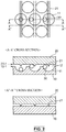
- Fig. 1 shows schematic diagrams illustrating a top plate and a container body in the culture container according to the present embodiment
- Fig. 2 shows a partially enlarged schematic plan view and cross-sectional views of the culture container according to the present embodiment.
- the culture container of the present embodiment is a culture container including a plurality of recesses for accommodating a culture target, and is formed by bonding a container body 10 and a top plate 20 as shown in Fig. 1 by heat sealing or the like.
- the container body 10 has a first surface 10-1 in which openings 12 of recesses 11 are formed, and the first surface 10-1 and the surface that forms the side walls of the recesses 11 are used as a culture surface to configure the bottom of the culture container.
- the number of recesses 11 is not particularly limited.
- the top plate 20 has a second surface 20-1 facing the first surface 10-1 of the container body 10.
- the first surface 10-1 of the container body 10 and the second surface 20-1 of the top plate 20 are disposed to face each other to form a culture container, and the container body 10 and the top plate 20 are partially in contact with each other to form a channel between the container body 10 and the top plate 20.
- the width of the channel is smaller than the minimum diameter of a culture target 30.
- the channel is formed by protrusion portions in the first and second embodiments, and is formed by channel portions in the third and fourth embodiments.
- the culture container of the present embodiment includes top plate protrusion portions 21 on the second surface 20-1 side of the top plate 20.
- the width of the top plate protrusion portion 21 is smaller than the width of the opening 12 of the recess 11 of the container body 10, and the height of the top plate protrusion portion 21 is smaller than the minimum diameter of the culture target 30.
- the tips of the top plate protrusion portions 21 are in contact with a part of the first surface 10-1 of the container body 10 (other than regions corresponding to the openings 12) in contact with each to form a gap between the first surface 10-1 of the container body 10 and the second surface 20-1 of the top plate 20.
- Fig. 2 shows a schematic plan view illustrating a state in which spheres as the culture target 30 are accommodated in part of such a culture container, an A-A' cross-sectional view, and an A"-A"' cross-sectional view.
- the top plate protrusion portions 21 have an elongated triangular prism shape protruding from the second surface 20-1, and are arranged at regular intervals above all of the recesses; however, the shape and arrangement of the top plate protrusion portions 21 are not limited thereto. Various shapes and arrangements can be employed within the range in which a gap can be formed between the first surface 10-1 and the second surface 20-1.
- the top plate protrusion portions 21 can have, for example, a semicircular cylindrical shape protruding from the second surface 20-1, and can be arranged at random on the second surface 20-1.
- the gap between the first surface 10-1 of the container body 10 and the second surface 20-1 of the top plate 20 is the same as the height of the top plate protrusion portion 21, and the height of the top plate protrusion portion 21 is smaller than the diameter of the culture target.
- the culture target cannot pass through the gap between the first surface 10-1 and the second surface 20-1, and can be retained in the recesses 11.
- the culture target such as spheres, can neither move from the recesses nor enter the neighboring recesses.
- the culture container of the present embodiment makes it possible to solve the conventional problem that it is difficult to obtain spheres with a desired size and shape.
- the culture container can be easily moved while culturing spheres.
- the medium in the culture container can be easily inserted and removed through the gap between the first surface and the second surface by tilting or inverting the culture container. That is, the medium can be easily homogenized when inserted, and the medium can also be easily discharged. In addition, a cleaning liquid can also be easily inserted and removed in this manner.
- the culture container of the present embodiment can keep the spheres in the recesses even when the culture container is tilted or inverted, which can facilitate the replacement of the medium.
- the culture container of the present embodiment can also be used to clean the culture target.
- a cleaning liquid such as a phosphate buffer, physiological saline, or a cell preservation liquid
- a cleaning liquid such as a phosphate buffer, physiological saline, or a cell preservation liquid
- the culture container is tilted or inverted to discharge the cleaning liquid from the culture container, whereby the culture target can be easily cleaned.
- sphere cleaning the following operation was carried out several times: spheres were once collected and suspended in a container, such as a centrifuge tube, filled with a cleaning liquid, and after the spheres were settled, the supernatant in cleaning was removed. Since spheres have a tendency to aggregate when they come into contact with each other, it is necessary to carry out the cleaning operation in a short time. Conventional methods had a risk of aggregation of spheres in the worst case; however, this problem can be easily solved by the culture container of the present embodiment.
- the culture container of the present embodiment makes it possible to obtain culture targets in a state of being arranged in sections each including a plurality of recesses, and to obtain the culture targets with a uniform size depending on the recesses.
- the culture targets can be easily counted.
- the culture container of the present embodiment also makes it possible to store or transport a culture target while accommodating the culture target in the recesses and filling the recesses and the channel formed between the container body and the top plate with a medium, a cleaning liquid, or a cell preservation liquid.
- the culture container of the present embodiment is used to perform medium replacement, cleaning, transportation, etc., while filling the recesses and the channel formed between the container body and the top plate with a medium, a cleaning liquid, or the like. It is needless to say that the container body and the top plate do not have through holes or the like.
- the culture target 30 in the present embodiment cells, body tissues, etc., can also be used, in addition to spheres.
- the culture target 30 also includes objects to be cleaned.
- the culture container can be applied to the culture of various culture targets 30 and to the cleaning thereof.
- the container body 10 and/or the top plate 20 can be made of a flexible packaging material, and can be configured as a culture bag. That is, in the culture container of the present embodiment, the tips of the top plate protrusion portions 21 can be easily brought into contact with a part of the first surface of the container body 10 by pressing the top plate 20 against the container body 10, and the contact state can be maintained. At this time, for example, the container body 10 can be pressed by the top plate 20 using a spring or a magnet, or by means of suction. It is possible to appropriately control the width of the channel formed between the container body 10 and the top plate 20.
- the width of the channel formed between the container body 10 and the top plate 20 can be easily controlled by pressing the top plate 20 against the container body 10. Since the width of the top plate protrusion portion 21 is smaller than the width of the opening 12 of the recess 11, the top plate protrusion portions 21 may be positioned anywhere with respect to the recesses 11, which can eliminate the need for strict alignment of the container body 10 and the top plate 20.
- the size of single cells is about 6 ⁇ m to 15 ⁇ m, and many of them have a size of about 10 ⁇ m.
- One sphere can be formed by aggregation of about 300 to several thousands of single cells. The size of the thus-formed spheres is about 50 ⁇ m to 100 ⁇ m for small spheres, and about 200 ⁇ m to 300 ⁇ m for large spheres.
- the culture container of the present embodiment it is desirable in the culture container of the present embodiment to set the width (height of the top plate protrusion portion 21) of the channel (gap) formed between the container body 10 and the top plate 20 depending on the size of the desired spheres.
- the width of the channel is preferably set to about 10 ⁇ m, 20 ⁇ m, 30 ⁇ m, or 40 ⁇ m.
- the width of the channel is preferably set to about 50 ⁇ m, 60 ⁇ m, 70 ⁇ m, 80 ⁇ m, 90 ⁇ m, or 100 ⁇ m.
- the culture container of the present embodiment when the culture target is single cells, it is preferable in the culture container of the present embodiment to set the width of the channel formed between the container body 10 and the top plate 20 to, for example, about 2 ⁇ m, 3 ⁇ m, 4 ⁇ m, or 5 ⁇ m.
- the culture target is a body tissue
- the recesses 11 of the container body 10 have a hemispherical shape in the examples of Figs. 1 and 2 , but are not limited thereto. Their shape may also be a conical shape, a truncated conical shape, a polygonal prism shape, a polygonal pyramid shape, a truncated polygonal shape, or the like.
- polyolefin-based resins such as polyethylene and polypropylene
- polyethylene and polypropylene examples thereof include polyethylene, ethylene- ⁇ -olefin copolymers, ethylene-vinyl acetate copolymers, ionomers using ethylene-acrylic acid or methacrylic acid copolymers and metal ions, and the like.
- Other examples include polyolefins, styrene-based elastomers, polyester-based thermoplastic elastomers, silicone-based thermoplastic elastomers, silicone resins, and the like.
- Still other examples include silicone rubber, flexible polyvinyl chloride resins, polybutadiene resins, ethylene-vinyl acetate copolymers, chlorinated polyethylene resins, polyurethane-based thermoplastic elastomers, polyester-based thermoplastic elastomers, silicone-based thermoplastic elastomers, styrene-based elastomers (e.g., SBS (styrene-butadiene-styrene), SIS (styrene-isoprene-styrene), SEBS (styrene-ethylene-butylene-styrene), and SEPS (styrene-ethylene-propylene-styrene)), polyolefin resins, fluorine-based resins, and the like.
- SBS styrene-butadiene-styrene
- SIS styrene-isoprene-styrene
- SEBS
- the first surface 10-1 and the surface that forms the side walls of the recesses 11 of the container body 10 are preferably subjected to low-adhesion surface coating so that the spheres and single cells do not adhere thereto.
- a cell adhesion inhibitor cell adhesion-reducing agent
- cell adhesion inhibitors include phospholipid polymers, polyvinyl alcohol derivatives, phospholipid-polymer complexes, polyhydroxyethyl methacrylate, polyvinyl alcohol, agarose, chitosan, polyethylene glycol, albumin, and the like. These can be used in combination.
- the culture container of the present embodiment can be used, for example, in a step of sphere formation, a step of culture and growth while maintaining the sphere state, and a step of differentiation induction in the sphere state.
- the culture container of the present embodiment can also be used, for example, in a method of forming spheres using differentiated cells obtained through a differentiation induction process from iPS cells, ES cells, or other stem cells, or a method of once cryopreserving differentiated cells, thawing them again, and then forming spheres.
- spheres formed to contain desired differentiation-inducing cells can be cleaned with a phosphate buffer or physiological saline, or suspended in water for injection, before administration to the living body.
- the spheres may be cleaned with a cleaning liquid fed in the culture container; or after the formation of spheres in another culture container, such as a bioreactor, the spheres may be transferred to the culture container of the present embodiment and cleaned in a state in which the spheres do not overlap each other.
- differentiated cells induced by adherent culture or in the sphere state are not always administered immediately to the living body; they may be once cryopreserved and thawed before use.
- the use of the culture container of the present embodiment facilitates not only medium replacement but also sphere cleaning in sphere culture, it is very advantageous in sphere culture.
- spheres are mass-cultured in a bioreactor or the like, and frozen after being returned to single cells, it is easy to subsequently form and clean spheres, and then suspend them in water for injection for each dose using the culture container of the present embodiment.
- the culture container of the present embodiment can be particularly suitably used for a culture bag made of a flexible packaging material. This makes it possible to solve the problems of conventional culture bags having many recesses in their culture surface.
- the flow rate near the port is particularly higher, and the spheres near the port become easier to move. Therefore, in order to sufficiently prevent the movement of the spheres near the port, the medium could only be fed at a flow rate of about 0.02 ml/min in some cases.
- the culture container of the present embodiment can feed the medium without taking the flow rate into consideration; thus, the spheres can be cultured efficiently.
- the medium can be fed at a rate of 5 ml/min.
- the culture container of the present embodiment is not limited to a culture bag made of a flexible packaging material, and can also be a dish-shaped rigid culture container.
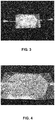
- Figs. 3 and 4 show photographs of a culture container produced as the culture container according to the present embodiment.
- This culture container is made of polyethylene, and is formed by bonding a container body 10 and a top plate 20, each of which has a size of 12 cm ⁇ 7 cm, by heat sealing. Ports are provided at both ends, the diameter of the recess is 2 mm, the height of the top plate protrusion portion is 50 ⁇ m, and the width of the top plate protrusion portion is 100 ⁇ m. In addition, the top plate protrusion portions are arranged at intervals of 2 mm so as to cover the entire culture surface.
- beads with a diameter of 200 ⁇ m were placed in the recesses of this culture container, a medium was fed while the top plate was pressed against the container body. It was confirmed that the beads did not pop out of the recesses or move to the neighboring recesses.
- Fig. 5 shows a partially enlarged schematic plan view and a cross-sectional view of the culture container according to the present embodiment.
- the culture container of the present embodiment is a culture container including a plurality of recesses for accommodating a culture target, and includes a container body 10b and a top plate 20b, as shown in Fig. 5 .
- the container body 10b has a first surface 10b-1 in which openings 12b of recesses 11b are formed, and the first surface 10b-1 and the surface that forms the side walls of the recesses 11b are used as a culture surface to configure the bottom of the culture container.
- the top plate 20b has a second surface 20b-1 facing the first surface 10b-1 of the container body 10b.
- the first surface 10b-1 of the container body 10b and the second surface 20b-1 of the top plate 20b are disposed to face each other to form a culture container, and the container body 10b and the top plate 20b are partially in contact with each other to form a channel between the container body 10b and the top plate 20b.
- the width of the channel is smaller than the minimum diameter of a culture target 30.
- the culture container of the present embodiment includes body protrusion portions 13b on the first surface 10b-1 side of the container body 10b.
- the height of the body protrusion portion 13b is smaller than the minimum diameter of the culture target 30.
- the tips of the body protrusion portions 13b are in contact with a part of the second surface 20b-1 of the top plate 20 to form a gap between the first surface 10b-1 of the container body 10b and the second surface 20b-1 of the top plate 20b.
- Fig. 5 shows a schematic plan view illustrating a state in which spheres as the culture target 30 are accommodated in part of such a culture container, and a B-B' cross-sectional view.
- the body protrusion portions 13b have a triangular prism shape protruding from the first surface 10-1, and are uniformly arranged between all of the recesses; however, the shape and arrangement of the body protrusion portions 13b are not limited thereto. Various shapes and arrangements can be employed within the range in which a gap can be formed between the first surface 10b-1 and the second surface 20b-1.
- the body protrusion portions 13b can have, for example, a semicircular cylindrical shape protruding from the first surface 10b-1, and can be arranged at random on the first surface 10b-1.
- the gap between the first surface 10b-1 of the container body 10b and the second surface 20b-1 of the top plate 20b is the same as the height of the body protrusion portion 13b, and the height of the body protrusion portion 13b is smaller than the diameter of the culture target.
- the culture target cannot pass through the gap between the first surface 10b-1 and the second surface 20b-1, and can be retained in the recesses 11b.
- Fig. 6 shows a partially enlarged schematic plan view and a cross-sectional view of the culture container according to the present embodiment.
- the culture container of the present embodiment is a culture container including a plurality of recesses for accommodating a culture target, and includes a container body 10c and a top plate 20c, as shown in Fig. 6 .
- the container body 10c has a first surface 10c-1 in which openings 12c of recesses 11c are formed, and the first surface 10c-1 and the surface that forms the side walls of the recesses 11c are used as a culture surface to configure the bottom of the culture container.
- the top plate 20c has a second surface 20c-1 facing the first surface 10c-1 of the container body 10c. In Fig. 6 , these surfaces are partially in contact with each other.
- the first surface 10c-1 of the container body 10c and the second surface 20c-1 of the top plate 20c are disposed to face each other to form a culture container, and the container body 10c and the top plate 20c are partially in contact with each other to form a channel between the container body 10c and the top plate 20c.
- the width of the channel is smaller than the minimum diameter of a culture target 30.
- the culture container of the present embodiment includes body channel portions 14c on the first surface 10c-1 side of the container body 10c.
- the body channel portions 14c are provided between the recesses 11c so as to connect all of the recesses 11c to one space.
- connection all of the recesses 11c to one space means that while the first surface 10c-1 and the second surface 20c-1 are partially in contact with each other, all of the recess 11c form one space so that the medium can be fed into all of the recesses 11c.
- the width of the body channel portion 14c is smaller than the minimum diameter of the culture target 30.
- first surface 10c-1 and the second surface 20c-1 are partially (other than regions corresponding to the openings 12c and the body channel portions 14c) in contact with each other to form the body channel portions 14c between the container body 10c and the top plate 20c.
- Fig. 6 shows a schematic plan view illustrating a state in which spheres as the culture target 30 are accommodated in part of such a culture container, and a C-C' cross-sectional view.
- the body channel portions 14c are formed in a substantially cylindrical shape uniformly between all of the recesses; however, the shape and arrangement of the body channel portions 14c are not limited thereto. Various shapes and arrangements can be employed within the range in which a channel can be formed between the container body 10c and the top plate 20c.
- the body channel portions 14c can have, for example, a prism shape, and can be arranged at random to connect all of the recesses 11c to one space.
- the first surface 10c-1 and the second surface 20c-1 are in contact with each other, and the width of the body channel portion 14c is smaller than the diameter of the culture target.
- the culture target cannot pass through the body channel portions 14c, and can be retained in the recesses 11c.
- Fig. 7 shows a partially enlarged schematic plan view and a cross-sectional view of the culture container according to the present embodiment.
- the culture container of the present embodiment is a culture container including a plurality of recesses for accommodating a culture target, and includes a container body 10d and a top plate 20d, as shown in Fig. 7 .
- the container body 10d has a first surface 10d-1 in which openings 12d of recesses 11d are formed, and the first surface 10d-1 and the surface that forms the side walls of the recesses 11d are used as a culture surface to configure the bottom of the culture container.
- the top plate 20d has a second surface 20d-1 facing the first surface 10d-1 of the container body 10d. In Fig. 7 , these surfaces are partially in contact with each other.
- the first surface 10d-1 of the container body 10d and the second surface 20d-1 of the top plate 20d are disposed to face each other to form a culture container, and the container body 10d and the top plate 20d are partially in contact with each other to form a channel between the container body 10d and the top plate 20d.
- the width of the channel is smaller than the minimum diameter of a culture target 30.
- the culture container of the present embodiment includes top plate channel portions 22d on the second surface 20d-1 side of the top plate 20d.
- the top plate channel portions 22d are provided on the top plate 20 so as to connect all of the recesses 11d to one space.
- the width of the top plate channel portion 22d is smaller than the minimum diameter of the culture target 30.
- first surface 10d-1 and the second surface 20d-1 are partially (other than regions corresponding to the openings 12d and the top plate channel portions 22d) in contact with each other to form the top plate channel portions 22d between the container body 10d and the top plate 20d.
- Fig. 7 shows a schematic plan view illustrating a state in which spheres as the culture target 30 are accommodated in part of such a culture container, and a D-D' cross-sectional view.
- the top plate channel portions 22d have a substantially cylindrical shape, and are formed uniformly to connect all of the recesses; however, the shape and arrangement of the top plate channel portions 22d are not limited thereto. Various shapes and arrangements can be employed within the range in which a channel can be formed between the container body 10d and top plate 20d.
- the top plate channel portions 22d can have, for example, a prism shape, and can be arranged at random to connect all of the recesses 11d to one space.
- the first surface 10d-1 and the second surface 20d-1 are partially (other than regions corresponding to the openings 12d and the top plate channel portions 22d) in contact with each other, and the width of the top plate channel portion 22d is smaller than the diameter of the culture target.
- the culture target cannot pass through the top plate channel portions 22d, and can be retained in the recesses 11d.
- the configurations of the culture containers of the first and second embodiments can be combined so that top plate protrusion portions are provided on the second surface, and body protrusion portions are provided between a plurality of recesses in the first surface.
- the height of the top plate protrusion portion is the same as the height of the body protrusion portion, and a gap that is the same as the height of these portions and smaller than the minimum diameter of the culture target is formed between the first surface and the second surface.
- the configuration of the culture container of the first and/or second embodiment and the configuration of the culture container of the third embodiment can be combined so that at least either of top plate protrusion portions and body protrusion portions are provided, and body channel portions are provided in the first surface.
- a gap is formed out of contact with the first surface and the second surface, and the sum of the width of the body channel portion and the width of the gap between the first surface and the second surface is smaller than the minimum diameter of the culture target.
- the configuration of the culture container of the first and/or second embodiment and the configuration of the culture container of the fourth embodiment can be combined so that at least either of top plate protrusion portions and body protrusion portions are provided, and top plate channel portions are provided in the second surface.
- a gap is formed out of contact with the first surface and the second surface, and the sum of the width of the top plate channel portion and the width of the gap between the first surface and the second surface is smaller than the minimum diameter of the culture target.
- the configurations of the culture containers of the third and fourth embodiments can be combined so that body channel portions and top plate channel portions are provided.
- the first surface and the second surface are partially in contact with each other, and the sum of the width of the body channel portion and the width of the top plate channel portion is smaller than the minimum diameter of the culture target.
- the height of the top plate protrusion portion is the same as the height of the body protrusion portion, a gap is formed out of contact with the first surface and the second surface, and the sum of the width of the gap between the first surface and the second surface, the width of the body channel portion, and the width of the top plate channel portion is smaller than the minimum diameter of the culture target.
- the culture container including a plurality of recesses for culturing a culture target, such as spheres
- a liquid substance such as a medium
- the size of the culture container is not limited to the size shown in the embodiments, and can be suitably changed to a size that can form, for example, 500,000 to a million of spheres.
- the present invention can be suitably used, for example, for efficiently mass-producing spheres with a uniform size arranged at regular intervals.
Landscapes
- Health & Medical Sciences (AREA)
- Chemical & Material Sciences (AREA)
- Wood Science & Technology (AREA)
- Zoology (AREA)
- Engineering & Computer Science (AREA)
- Bioinformatics & Cheminformatics (AREA)
- Organic Chemistry (AREA)
- Life Sciences & Earth Sciences (AREA)
- Biotechnology (AREA)
- Genetics & Genomics (AREA)
- Biomedical Technology (AREA)
- Microbiology (AREA)
- Biochemistry (AREA)
- General Engineering & Computer Science (AREA)
- General Health & Medical Sciences (AREA)
- Sustainable Development (AREA)
- Clinical Laboratory Science (AREA)
- Analytical Chemistry (AREA)
- Immunology (AREA)
- Dispersion Chemistry (AREA)
- Apparatus Associated With Microorganisms And Enzymes (AREA)
- Micro-Organisms Or Cultivation Processes Thereof (AREA)
Abstract
Description
- The present invention relates to a cell culture-related technique, in particular, relates to a technique of promoting the efficiency of sphere formation and the like.
- In recent years, large amounts of adherent cells, such as stem cells including iPS cells and ES cells, are cultured not only by attaching cells to a culture container to grow, but also by using a method of culturing cells in a three-dimensional state closer to in vivo by forming spheres (spheroids, aggregates) and organoids using a culture container including a microwell plate etc., coated with a material having low adhesion to cells.
- The mass culture of spheres using such a culture container had a problem that it was difficult to obtain spheres with a desired size and shape because the spheres popped out of the wells (recesses) and moved to other wells.
- For example, when a medium was fed into a culture bag (bag-shaped culture container) including many wells on its culture surface in order to replace the medium, the spheres easily popped out of the wells and moved to other wells. It was thus necessary to extremely slow down the flow rate of the medium, and it was very difficult to replace the medium quickly. Therefore, this type of culture container was not suitable for long-term culture, which required frequent medium replacement.
- In addition, in such a culture container, the spheres easily popped out of the wells only upon vibration, and it was thus not easy to move the culture container safely while culturing spheres.
-
- Patent Document 1:
JP-A-2018-108032 - Patent Document 2:
JP-A-2018-50 - An example of techniques related to solutions of such problems is the culture vessel disclosed in
Patent Document 1. The culture vessel includes a vessel main body including a bottom portion formed with a compartment, and a peripheral wall portion rising from an edge portion of the bottom portion; and a partition member disposed at a position opposed to the bottom portion; and at least a portion of the partition member is immersed in the culture liquid within the vessel main body. This can prevent the movement of spheres during movement of the culture vessel or replacement of the medium. - However, there was a problem that it was difficult to align the peripheral wall portion of the compartment with the partition member and to adjust the gap between the compartment and the partition member. In addition, the alignment and adjustment became more difficult when the bottom portion and the partition member were warped. For this reason, it was difficult to apply this culture vessel to a culture bag made of a flexible packaging material.
- Another example is the cell culture container disclosed in Patent Document 2. The cell culture container includes a container body and a lid body capable of being freely taken in and out with respect to the bore of the container body, a plurality of crevices for containing cells are arranged in the bottom face of the bore, and the lid body is made of a liquid-permeable material with flexibility. In the condition that the lid body is immersed in culture medium, the under face of the lid body is formed so as to follow the bottom face. This makes it possible to confine spheres to a compartment.
- However, it was also difficult to apply this cell culture container particularly to a culture bag made of a flexible packaging material because a gap was sometimes formed between the crevices and the lid body when the container body was warped. In addition, with this cell culture container, it was difficult to discharge the whole culture medium in the crevices, and it was not suitable for rapid medium replacement.
- Then, as a result of extensive studies, the present inventors have succeeded in developing a culture container including a container body having a first surface in which recesses are formed, and a top plate having a second surface facing the first surface, protrusion portions and/or channel portions being provided on a side of the first surface and/or a side of the second surface, the container body and the top plate being partially in contact with each other to form a channel between the container body and the top plate, and the channel having a width smaller than the minimum diameter of a culture target, such as spheres; wherein a liquid substance, such as a medium, can flow between the number of recesses formed in the culture container, cells and debris smaller than the minimum diameter of the culture target can pass between the recesses, and the movement of spheres etc. between the recesses can be prevented.
- Moreover, this culture container does not require the alignment of the recesses and the top plate, and can be easily realized as a closed-type culture bag made of a flexible packaging material. Furthermore, since spheres etc. do not move between the recesses even when the medium is replaced, this culture container can be suitably used for long-term culture.
- The present invention was made in view of the above circumstances. An object of the present invention is to provide a culture container including a plurality of recesses for culturing a culture target, such as spheres, wherein a liquid substance can flow between the recesses and the movement of the culture target between the recesses can be prevented, and to also provide a culture method and a transportation method.
- In order to achieve the above object, the culture container of the present invention is a culture container including a plurality of recesses for accommodating a culture target, the culture container including a container body having a first surface in which the recesses are formed, and a top plate having a second surface facing the first surface, protrusion portions and/or channel portions being provided on a side of the first surface and/or a side of the second surface, the container body and the top plate being partially in contact with each other to form a channel between the container body and the top plate, and a width of the channel being smaller than a minimum diameter of the culture target.
- Further, the culture container of the present invention is preferably configured such that top plate protrusion portions are provided on the second surface side, a width of the top plate protrusion portion is smaller than a width of an opening of the recess, a height of the top plate protrusion portion is smaller than the minimum diameter of the culture target, and the top plate protrusion portions are in contact with a part of the first surface to form a gap between the first surface and the second surface.
- Moreover, the culture method of the present invention is a culture method using the above culture container, the method including inserting and removing a medium or a cleaning liquid through the channel formed between the container body and the top plate.
- In addition, the transportation method of the present invention is a method for storing or transporting the culture target using the above culture container while accommodating the culture target in the recesses and filling the recesses and the channel formed between the container body and the top plate with a medium, a cleaning liquid, or a cell preservation liquid.
- According to the present invention, it is possible to provide a culture container including a plurality of recesses for culturing a culture target, such as spheres, wherein a liquid substance can flow between the recesses and the movement of the culture target between the recesses can be prevented, and to also provide a culture method and a transportation method.
-
-
Fig. 1 shows schematic diagrams illustrating a top plate and a container body in a culture container according to a first embodiment of the present invention. -
Fig. 2 shows a partially enlarged schematic plan view and cross-sectional views of the culture container according to the first embodiment of the present invention. -
Fig. 3 is a picture of the entirety of a culture container produced as the culture container according to the first embodiment of the present invention. -
Fig. 4 is a picture of part of the culture container produced as the culture container according to the first embodiment of the present invention. -
Fig. 5 shows a partially enlarged schematic plan view and a cross-sectional view of a culture container according to a second embodiment of the present invention. -
Fig. 6 shows a partially enlarged schematic plan view and a cross-sectional view of a culture container according to a third embodiment of the present invention. -
Fig. 7 shows a partially enlarged schematic plan view and a cross-sectional view of a culture container according to a fourth embodiment of the present invention. - Hereinafter, embodiments of the culture container, the culture method, and the transportation method according to the present invention will be described in detail. Note that the present invention is not limited to the specific contents of the following embodiments.
- The culture container, the culture method, and the transportation method according to the first embodiment of the present invention will be described with reference to
Figs. 1 and2 .Fig. 1 shows schematic diagrams illustrating a top plate and a container body in the culture container according to the present embodiment, andFig. 2 shows a partially enlarged schematic plan view and cross-sectional views of the culture container according to the present embodiment. - The culture container of the present embodiment is a culture container including a plurality of recesses for accommodating a culture target, and is formed by bonding a
container body 10 and atop plate 20 as shown inFig. 1 by heat sealing or the like. - The
container body 10 has a first surface 10-1 in whichopenings 12 ofrecesses 11 are formed, and the first surface 10-1 and the surface that forms the side walls of therecesses 11 are used as a culture surface to configure the bottom of the culture container. The number ofrecesses 11 is not particularly limited. - The
top plate 20 has a second surface 20-1 facing the first surface 10-1 of thecontainer body 10. - Then, the first surface 10-1 of the
container body 10 and the second surface 20-1 of thetop plate 20 are disposed to face each other to form a culture container, and thecontainer body 10 and thetop plate 20 are partially in contact with each other to form a channel between thecontainer body 10 and thetop plate 20. The width of the channel is smaller than the minimum diameter of aculture target 30. The channel is formed by protrusion portions in the first and second embodiments, and is formed by channel portions in the third and fourth embodiments. - Specifically, the culture container of the present embodiment includes top
plate protrusion portions 21 on the second surface 20-1 side of thetop plate 20. - The width of the top
plate protrusion portion 21 is smaller than the width of theopening 12 of therecess 11 of thecontainer body 10, and the height of the topplate protrusion portion 21 is smaller than the minimum diameter of theculture target 30. - Then, the tips of the top
plate protrusion portions 21 are in contact with a part of the first surface 10-1 of the container body 10 (other than regions corresponding to the openings 12) in contact with each to form a gap between the first surface 10-1 of thecontainer body 10 and the second surface 20-1 of thetop plate 20. -
Fig. 2 shows a schematic plan view illustrating a state in which spheres as theculture target 30 are accommodated in part of such a culture container, an A-A' cross-sectional view, and an A"-A"' cross-sectional view. - In the A-A' cross-sectional view, the top
plate protrusion portions 21 have an elongated triangular prism shape protruding from the second surface 20-1, and are arranged at regular intervals above all of the recesses; however, the shape and arrangement of the topplate protrusion portions 21 are not limited thereto. Various shapes and arrangements can be employed within the range in which a gap can be formed between the first surface 10-1 and the second surface 20-1. - That is, the top
plate protrusion portions 21 can have, for example, a semicircular cylindrical shape protruding from the second surface 20-1, and can be arranged at random on the second surface 20-1. - The gap between the first surface 10-1 of the
container body 10 and the second surface 20-1 of thetop plate 20 is the same as the height of the topplate protrusion portion 21, and the height of the topplate protrusion portion 21 is smaller than the diameter of the culture target. - Therefore, the culture target cannot pass through the gap between the first surface 10-1 and the second surface 20-1, and can be retained in the
recesses 11. - That is, even if a liquid substance, such as a medium, is fed through the gap between the first surface and the second surface, the culture target, such as spheres, can neither move from the recesses nor enter the neighboring recesses.
- Therefore, the culture container of the present embodiment makes it possible to solve the conventional problem that it is difficult to obtain spheres with a desired size and shape.
- Further, even if the flow rate of the medium is increased, the spheres do not pop out of the recesses or move to other recesses; thus, the medium can be easily inserted and removed to facilitate the replacement of the medium. In addition, the culture container can be easily moved while culturing spheres.
- Furthermore, in the case of replacing the entire medium, the medium in the culture container can be easily inserted and removed through the gap between the first surface and the second surface by tilting or inverting the culture container. That is, the medium can be easily homogenized when inserted, and the medium can also be easily discharged. In addition, a cleaning liquid can also be easily inserted and removed in this manner.
- Thus, the culture container of the present embodiment can keep the spheres in the recesses even when the culture container is tilted or inverted, which can facilitate the replacement of the medium.
- The culture container of the present embodiment can also be used to clean the culture target.
- That is, a cleaning liquid, such as a phosphate buffer, physiological saline, or a cell preservation liquid, is injected into the culture container, and the culture container is tilted or inverted to discharge the cleaning liquid from the culture container, whereby the culture target can be easily cleaned. In general sphere cleaning, the following operation was carried out several times: spheres were once collected and suspended in a container, such as a centrifuge tube, filled with a cleaning liquid, and after the spheres were settled, the supernatant in cleaning was removed. Since spheres have a tendency to aggregate when they come into contact with each other, it is necessary to carry out the cleaning operation in a short time. Conventional methods had a risk of aggregation of spheres in the worst case; however, this problem can be easily solved by the culture container of the present embodiment.
- Moreover, the culture container of the present embodiment makes it possible to obtain culture targets in a state of being arranged in sections each including a plurality of recesses, and to obtain the culture targets with a uniform size depending on the recesses.
- Furthermore, since it is possible to obtain culture targets in a state of being arranged in each section, the culture targets can be easily counted.
- In addition, the culture container of the present embodiment also makes it possible to store or transport a culture target while accommodating the culture target in the recesses and filling the recesses and the channel formed between the container body and the top plate with a medium, a cleaning liquid, or a cell preservation liquid.
- Thus, the culture container of the present embodiment is used to perform medium replacement, cleaning, transportation, etc., while filling the recesses and the channel formed between the container body and the top plate with a medium, a cleaning liquid, or the like. It is needless to say that the container body and the top plate do not have through holes or the like.
- As the
culture target 30 in the present embodiment, cells, body tissues, etc., can also be used, in addition to spheres. Theculture target 30 also includes objects to be cleaned. - That is, when the width of the channel formed between the
container body 10 and thetop plate 20 is set to a value suitable for the size of theculture target 30, the culture container can be applied to the culture ofvarious culture targets 30 and to the cleaning thereof. - Further, in the culture container of the present embodiment, the
container body 10 and/or thetop plate 20 can be made of a flexible packaging material, and can be configured as a culture bag. That is, in the culture container of the present embodiment, the tips of the topplate protrusion portions 21 can be easily brought into contact with a part of the first surface of thecontainer body 10 by pressing thetop plate 20 against thecontainer body 10, and the contact state can be maintained. At this time, for example, thecontainer body 10 can be pressed by thetop plate 20 using a spring or a magnet, or by means of suction. It is possible to appropriately control the width of the channel formed between thecontainer body 10 and thetop plate 20. - Moreover, in the culture container of the present embodiment, the width of the channel formed between the
container body 10 and thetop plate 20 can be easily controlled by pressing thetop plate 20 against thecontainer body 10. Since the width of the topplate protrusion portion 21 is smaller than the width of theopening 12 of therecess 11, the topplate protrusion portions 21 may be positioned anywhere with respect to therecesses 11, which can eliminate the need for strict alignment of thecontainer body 10 and thetop plate 20. - Here, the size of single cells is about 6 µm to 15 µm, and many of them have a size of about 10 µm. One sphere can be formed by aggregation of about 300 to several thousands of single cells. The size of the thus-formed spheres is about 50 µm to 100 µm for small spheres, and about 200 µm to 300 µm for large spheres.
- Accordingly, when the culture target is spheres, it is desirable in the culture container of the present embodiment to set the width (height of the top plate protrusion portion 21) of the channel (gap) formed between the
container body 10 and thetop plate 20 depending on the size of the desired spheres. For example, to form small spheres, the width of the channel is preferably set to about 10 µm, 20 µm, 30 µm, or 40 µm. Further, to form large spheres, the width of the channel is preferably set to about 50 µm, 60 µm, 70 µm, 80 µm, 90 µm, or 100 µm. - Moreover, when the culture target is single cells, it is preferable in the culture container of the present embodiment to set the width of the channel formed between the
container body 10 and thetop plate 20 to, for example, about 2 µm, 3 µm, 4 µm, or 5 µm. - Furthermore, when the culture target is a body tissue, it is desirable in the culture container of the present embodiment to set the width of the channel formed between the
container body 10 and thetop plate 20 depending on the size of the target body tissue. - In addition, in the culture container of the present embodiment, the
recesses 11 of thecontainer body 10 have a hemispherical shape in the examples ofFigs. 1 and2 , but are not limited thereto. Their shape may also be a conical shape, a truncated conical shape, a polygonal prism shape, a polygonal pyramid shape, a truncated polygonal shape, or the like. - As the materials of the
container body 10 and thetop plate 20 in the culture container of the present embodiment, polyolefin-based resins, such as polyethylene and polypropylene, can be suitably used. Examples thereof include polyethylene, ethylene-α-olefin copolymers, ethylene-vinyl acetate copolymers, ionomers using ethylene-acrylic acid or methacrylic acid copolymers and metal ions, and the like. Other examples include polyolefins, styrene-based elastomers, polyester-based thermoplastic elastomers, silicone-based thermoplastic elastomers, silicone resins, and the like. Still other examples include silicone rubber, flexible polyvinyl chloride resins, polybutadiene resins, ethylene-vinyl acetate copolymers, chlorinated polyethylene resins, polyurethane-based thermoplastic elastomers, polyester-based thermoplastic elastomers, silicone-based thermoplastic elastomers, styrene-based elastomers (e.g., SBS (styrene-butadiene-styrene), SIS (styrene-isoprene-styrene), SEBS (styrene-ethylene-butylene-styrene), and SEPS (styrene-ethylene-propylene-styrene)), polyolefin resins, fluorine-based resins, and the like. - The same applies to the materials of the top
plate protrusion portions 21 andbody protrusion portions 13b, described later, in the present embodiment. - Moreover, when the
culture target 30 is spheres, in the culture container of the present embodiment, the first surface 10-1 and the surface that forms the side walls of therecesses 11 of thecontainer body 10 are preferably subjected to low-adhesion surface coating so that the spheres and single cells do not adhere thereto. Specifically, it is preferable to apply a cell adhesion inhibitor (cell adhesion-reducing agent). - Usable examples of cell adhesion inhibitors include phospholipid polymers, polyvinyl alcohol derivatives, phospholipid-polymer complexes, polyhydroxyethyl methacrylate, polyvinyl alcohol, agarose, chitosan, polyethylene glycol, albumin, and the like. These can be used in combination.
- When the
culture target 30 is spheres, the culture container of the present embodiment can be used, for example, in a step of sphere formation, a step of culture and growth while maintaining the sphere state, and a step of differentiation induction in the sphere state. - In addition, the culture container of the present embodiment can also be used, for example, in a method of forming spheres using differentiated cells obtained through a differentiation induction process from iPS cells, ES cells, or other stem cells, or a method of once cryopreserving differentiated cells, thawing them again, and then forming spheres.
- Further, spheres formed to contain desired differentiation-inducing cells can be cleaned with a phosphate buffer or physiological saline, or suspended in water for injection, before administration to the living body.
- Here, as the cleaning of spheres, after the formation of spheres in the culture container of the present embodiment, the spheres may be cleaned with a cleaning liquid fed in the culture container; or after the formation of spheres in another culture container, such as a bioreactor, the spheres may be transferred to the culture container of the present embodiment and cleaned in a state in which the spheres do not overlap each other.
- In addition, as described above, it is also possible to perform cleaning when differentiated cells are once cryopreserved and thawed again, and then spheres are formed.
- That is, differentiated cells induced by adherent culture or in the sphere state are not always administered immediately to the living body; they may be once cryopreserved and thawed before use.
- Because of the nature of cells, it is difficult to freeze cells in the sphere state. Even if differentiation is induced in spheres, it is necessary to break them into single cells before freezing.
- After the differentiated single cells are thawed, it is necessary to form spheres again for administration; however, before administration, it is necessary to clean the spheres to remove the medium in the sphere formation, debris, etc.
- However, sphere cleaning is not only time-consuming, as described above, but also poses a risk of contamination because it is often performed in an open system. In addition, its quality control is also costly.
- Since the use of the culture container of the present embodiment facilitates not only medium replacement but also sphere cleaning in sphere culture, it is very advantageous in sphere culture. For example, when spheres are mass-cultured in a bioreactor or the like, and frozen after being returned to single cells, it is easy to subsequently form and clean spheres, and then suspend them in water for injection for each dose using the culture container of the present embodiment.
- Moreover, the culture container of the present embodiment can be particularly suitably used for a culture bag made of a flexible packaging material. This makes it possible to solve the problems of conventional culture bags having many recesses in their culture surface.
- That is, in such a culture bag, when a medium is fed into the bag to replace the medium, the spheres easily pop out of the wells and move to other wells. Therefore, for example, in the case of a culture container with an outer diameter of 100 mm × 50 mm having circular wells with a diameter of 1 mm and a depth of 0.5 mm, the medium could only be fed at a flow rate of about 0.2 ml/min.
- In addition, in such a culture bag, the flow rate near the port is particularly higher, and the spheres near the port become easier to move. Therefore, in order to sufficiently prevent the movement of the spheres near the port, the medium could only be fed at a flow rate of about 0.02 ml/min in some cases.
- In contrast, the culture container of the present embodiment can feed the medium without taking the flow rate into consideration; thus, the spheres can be cultured efficiently. For example, with the culture container of the present embodiment, the medium can be fed at a rate of 5 ml/min.
- The culture container of the present embodiment is not limited to a culture bag made of a flexible packaging material, and can also be a dish-shaped rigid culture container.
-
Figs. 3 and 4 show photographs of a culture container produced as the culture container according to the present embodiment. - This culture container is made of polyethylene, and is formed by bonding a
container body 10 and atop plate 20, each of which has a size of 12 cm × 7 cm, by heat sealing. Ports are provided at both ends, the diameter of the recess is 2 mm, the height of the top plate protrusion portion is 50 µm, and the width of the top plate protrusion portion is 100 µm. In addition, the top plate protrusion portions are arranged at intervals of 2 mm so as to cover the entire culture surface. - In place of spheres, beads with a diameter of 200 µm were placed in the recesses of this culture container, a medium was fed while the top plate was pressed against the container body. It was confirmed that the beads did not pop out of the recesses or move to the neighboring recesses.
- Even when the culture container was inverted to discharge the entire medium from the recesses, the beads remained in the recesses.
- Next, the culture container, the culture method, and the transportation method according to the second embodiment of the present invention will be described with reference to
Fig. 5. Fig. 5 shows a partially enlarged schematic plan view and a cross-sectional view of the culture container according to the present embodiment. - The culture container of the present embodiment is a culture container including a plurality of recesses for accommodating a culture target, and includes a
container body 10b and atop plate 20b, as shown inFig. 5 . - The
container body 10b has afirst surface 10b-1 in whichopenings 12b ofrecesses 11b are formed, and thefirst surface 10b-1 and the surface that forms the side walls of therecesses 11b are used as a culture surface to configure the bottom of the culture container. - The
top plate 20b has asecond surface 20b-1 facing thefirst surface 10b-1 of thecontainer body 10b. - That is, the
first surface 10b-1 of thecontainer body 10b and thesecond surface 20b-1 of thetop plate 20b are disposed to face each other to form a culture container, and thecontainer body 10b and thetop plate 20b are partially in contact with each other to form a channel between thecontainer body 10b and thetop plate 20b. The width of the channel is smaller than the minimum diameter of aculture target 30. - Specifically, the culture container of the present embodiment includes
body protrusion portions 13b on thefirst surface 10b-1 side of thecontainer body 10b. - The height of the
body protrusion portion 13b is smaller than the minimum diameter of theculture target 30. - Then, the tips of the
body protrusion portions 13b are in contact with a part of thesecond surface 20b-1 of thetop plate 20 to form a gap between thefirst surface 10b-1 of thecontainer body 10b and thesecond surface 20b-1 of thetop plate 20b. -
Fig. 5 shows a schematic plan view illustrating a state in which spheres as theculture target 30 are accommodated in part of such a culture container, and a B-B' cross-sectional view. - In the B-B' cross-sectional view, the
body protrusion portions 13b have a triangular prism shape protruding from the first surface 10-1, and are uniformly arranged between all of the recesses; however, the shape and arrangement of thebody protrusion portions 13b are not limited thereto. Various shapes and arrangements can be employed within the range in which a gap can be formed between thefirst surface 10b-1 and thesecond surface 20b-1. - That is, the
body protrusion portions 13b can have, for example, a semicircular cylindrical shape protruding from thefirst surface 10b-1, and can be arranged at random on thefirst surface 10b-1. - The gap between the
first surface 10b-1 of thecontainer body 10b and thesecond surface 20b-1 of thetop plate 20b is the same as the height of thebody protrusion portion 13b, and the height of thebody protrusion portion 13b is smaller than the diameter of the culture target. - Therefore, the culture target cannot pass through the gap between the
first surface 10b-1 and thesecond surface 20b-1, and can be retained in therecesses 11b. - The other configurations and effects of the culture container of the present embodiment are the same as those of the first embodiment.
- The culture container, the culture method, and the transportation method according to the third embodiment of the present invention will be described with reference to
Fig. 6. Fig. 6 shows a partially enlarged schematic plan view and a cross-sectional view of the culture container according to the present embodiment. - The culture container of the present embodiment is a culture container including a plurality of recesses for accommodating a culture target, and includes a
container body 10c and atop plate 20c, as shown inFig. 6 . - The
container body 10c has afirst surface 10c-1 in whichopenings 12c ofrecesses 11c are formed, and thefirst surface 10c-1 and the surface that forms the side walls of therecesses 11c are used as a culture surface to configure the bottom of the culture container. - The
top plate 20c has asecond surface 20c-1 facing thefirst surface 10c-1 of thecontainer body 10c. InFig. 6 , these surfaces are partially in contact with each other. - That is, the
first surface 10c-1 of thecontainer body 10c and thesecond surface 20c-1 of thetop plate 20c are disposed to face each other to form a culture container, and thecontainer body 10c and thetop plate 20c are partially in contact with each other to form a channel between thecontainer body 10c and thetop plate 20c. The width of the channel is smaller than the minimum diameter of aculture target 30. - Specifically, the culture container of the present embodiment includes
body channel portions 14c on thefirst surface 10c-1 side of thecontainer body 10c. - The
body channel portions 14c are provided between therecesses 11c so as to connect all of therecesses 11c to one space. - The phrase "connect all of the
recesses 11c to one space" means that while thefirst surface 10c-1 and thesecond surface 20c-1 are partially in contact with each other, all of therecess 11c form one space so that the medium can be fed into all of therecesses 11c. The same applies to the fourth embodiment. - The width of the
body channel portion 14c is smaller than the minimum diameter of theculture target 30. - In the present embodiment, the
first surface 10c-1 and thesecond surface 20c-1 are partially (other than regions corresponding to theopenings 12c and thebody channel portions 14c) in contact with each other to form thebody channel portions 14c between thecontainer body 10c and thetop plate 20c. -
Fig. 6 shows a schematic plan view illustrating a state in which spheres as theculture target 30 are accommodated in part of such a culture container, and a C-C' cross-sectional view. - In the C-C' cross-sectional view, the
body channel portions 14c are formed in a substantially cylindrical shape uniformly between all of the recesses; however, the shape and arrangement of thebody channel portions 14c are not limited thereto. Various shapes and arrangements can be employed within the range in which a channel can be formed between thecontainer body 10c and thetop plate 20c. - That is, the
body channel portions 14c can have, for example, a prism shape, and can be arranged at random to connect all of therecesses 11c to one space. - In the present embodiment, the
first surface 10c-1 and thesecond surface 20c-1 (other than regions corresponding to theopenings 12c and thebody channel portions 14c) are in contact with each other, and the width of thebody channel portion 14c is smaller than the diameter of the culture target. - Therefore, the culture target cannot pass through the
body channel portions 14c, and can be retained in therecesses 11c. - The other configurations and effects of the culture container of the present embodiment are the same as those of the first embodiment.
- The culture container, the culture method, and the transportation method according to the fourth embodiment of the present invention will be described with reference to
Fig. 7. Fig. 7 shows a partially enlarged schematic plan view and a cross-sectional view of the culture container according to the present embodiment. - The culture container of the present embodiment is a culture container including a plurality of recesses for accommodating a culture target, and includes a
container body 10d and atop plate 20d, as shown inFig. 7 . - The
container body 10d has afirst surface 10d-1 in whichopenings 12d ofrecesses 11d are formed, and thefirst surface 10d-1 and the surface that forms the side walls of therecesses 11d are used as a culture surface to configure the bottom of the culture container. - The
top plate 20d has asecond surface 20d-1 facing thefirst surface 10d-1 of thecontainer body 10d. InFig. 7 , these surfaces are partially in contact with each other. - That is, the
first surface 10d-1 of thecontainer body 10d and thesecond surface 20d-1 of thetop plate 20d are disposed to face each other to form a culture container, and thecontainer body 10d and thetop plate 20d are partially in contact with each other to form a channel between thecontainer body 10d and thetop plate 20d. The width of the channel is smaller than the minimum diameter of aculture target 30. - Specifically, the culture container of the present embodiment includes top
plate channel portions 22d on thesecond surface 20d-1 side of thetop plate 20d. - The top
plate channel portions 22d are provided on thetop plate 20 so as to connect all of therecesses 11d to one space. - The width of the top
plate channel portion 22d is smaller than the minimum diameter of theculture target 30. - In the present embodiment, the
first surface 10d-1 and thesecond surface 20d-1 are partially (other than regions corresponding to theopenings 12d and the topplate channel portions 22d) in contact with each other to form the topplate channel portions 22d between thecontainer body 10d and thetop plate 20d. -
Fig. 7 shows a schematic plan view illustrating a state in which spheres as theculture target 30 are accommodated in part of such a culture container, and a D-D' cross-sectional view. - In the D-D' cross-sectional view, the top
plate channel portions 22d have a substantially cylindrical shape, and are formed uniformly to connect all of the recesses; however, the shape and arrangement of the topplate channel portions 22d are not limited thereto. Various shapes and arrangements can be employed within the range in which a channel can be formed between thecontainer body 10d andtop plate 20d. - That is, the top
plate channel portions 22d can have, for example, a prism shape, and can be arranged at random to connect all of therecesses 11d to one space. - In the present embodiment, the
first surface 10d-1 and thesecond surface 20d-1 are partially (other than regions corresponding to theopenings 12d and the topplate channel portions 22d) in contact with each other, and the width of the topplate channel portion 22d is smaller than the diameter of the culture target. - Therefore, the culture target cannot pass through the top
plate channel portions 22d, and can be retained in therecesses 11d. - The other configurations and effects of the culture container of the present embodiment are the same as those of the first embodiment.
- Further, it is also possible to combine the configurations of the culture containers of the first to fourth embodiments.
- Specifically, the configurations of the culture containers of the first and second embodiments can be combined so that top plate protrusion portions are provided on the second surface, and body protrusion portions are provided between a plurality of recesses in the first surface.
- In this case, the height of the top plate protrusion portion is the same as the height of the body protrusion portion, and a gap that is the same as the height of these portions and smaller than the minimum diameter of the culture target is formed between the first surface and the second surface.
- Moreover, the configuration of the culture container of the first and/or second embodiment and the configuration of the culture container of the third embodiment can be combined so that at least either of top plate protrusion portions and body protrusion portions are provided, and body channel portions are provided in the first surface.
- In this case, a gap is formed out of contact with the first surface and the second surface, and the sum of the width of the body channel portion and the width of the gap between the first surface and the second surface is smaller than the minimum diameter of the culture target.
- In addition, the configuration of the culture container of the first and/or second embodiment and the configuration of the culture container of the fourth embodiment can be combined so that at least either of top plate protrusion portions and body protrusion portions are provided, and top plate channel portions are provided in the second surface.
- In this case, a gap is formed out of contact with the first surface and the second surface, and the sum of the width of the top plate channel portion and the width of the gap between the first surface and the second surface is smaller than the minimum diameter of the culture target.
- Further, the configurations of the culture containers of the third and fourth embodiments can be combined so that body channel portions and top plate channel portions are provided.
- In this case, the first surface and the second surface are partially in contact with each other, and the sum of the width of the body channel portion and the width of the top plate channel portion is smaller than the minimum diameter of the culture target.
- In addition, all of the configurations of the culture containers of the first to fourth embodiments can be combined.
- In this case, the height of the top plate protrusion portion is the same as the height of the body protrusion portion, a gap is formed out of contact with the first surface and the second surface, and the sum of the width of the gap between the first surface and the second surface, the width of the body channel portion, and the width of the top plate channel portion is smaller than the minimum diameter of the culture target.
- As explained above, according to the culture container, the culture method, and the transportation method according to embodiments of the present invention, in the culture container including a plurality of recesses for culturing a culture target, such as spheres, a liquid substance, such as a medium, can flow between the recesses, cells and debris smaller than the minimum diameter of the culture target can pass between the recesses, and the movement of the culture target between the recesses can be prevented.
- The present invention is not limited to the above-mentioned embodiments, and it is needless to say that various modifications are possible within the scope of the present invention.
- For example, the size of the culture container is not limited to the size shown in the embodiments, and can be suitably changed to a size that can form, for example, 500,000 to a million of spheres.
- The present invention can be suitably used, for example, for efficiently mass-producing spheres with a uniform size arranged at regular intervals.
- The documents described in the specification and the Japanese patent application claiming the priority under the Paris Convention to the invention are incorporated herein by reference in its entirety.
-
- 10, 10b, 10c, 10d:
- Container body
- 10-1, 10b-1, 10c-1, 10d-1:
- First surface
- 11, 11b, 11c, 11d:
- Recess
- 12, 12b, 12c, 12d:
- Opening
- 13b:
- Body protrusion portion
- 14c:
- Body channel portion
- 20, 20b, 20c, 20d:
- Top plate
- 20-1, 20b-1, 20c-1, 20d-1:
- Second surface
- 21:
- Top plate protrusion portion
- 22d:
- Top plate channel portion
- 30:
- Culture target
Claims (12)
- A culture container comprising a plurality of recesses for accommodating a culture target, whereinthe culture container comprises a container body having a first surface in which the recesses are formed, and a top plate having a second surface facing the first surface,protrusion portions and/or channel portions are provided on a side of the first surface and/or a side of the second surface,the container body and the top plate are partially in contact with each other to form a channel between the container body and the top plate, anda width of the channel is smaller than a minimum diameter of the culture target.
- The culture container according to claim 1, whereintop plate protrusion portions are provided on the second surface side,a width of the top plate protrusion portion is smaller than a width of an opening of the recess, and a height of the top plate protrusion portion is smaller than the minimum diameter of the culture target, andthe top plate protrusion portions are in contact with a part of the first surface to form a gap between the first surface and the second surface.
- The culture container according to claim 1 or 2, whereinbody protrusion portions are provided between the plurality of recesses on the first surface side,a height of the body protrusion portion is smaller than the minimum diameter of the culture target, andthe body protrusion portions are in contact with a part of the second surface to form a gap between the first surface and the second surface.
- The culture container according to claim 1, whereinbody channel portions are provided on the first surface side,the body channel portions are provided between the recesses to connect all of the recesses to one space,a width of the body channel portion is smaller than the minimum diameter of the culture target, andthe first surface and the second surface are partially in contact with each other to form a channel between the container body and the top plate.
- The culture container according to claim 1, whereintop plate channel portions are provided on the second surface side,the top plate channel portions are provided to connect all of the recesses to one space,a width of the top plate channel portion is smaller than the minimum diameter of the culture target, andthe first surface and the second surface are partially in contact with each other to form a channel between the container body and the top plate.
- The culture container according to claim 2 or 3, whereinbody channel portions are provided on the first surface side,the body channel portions are provided between the recesses to connect all of the recesses to one space,a sum of a width of the body channel portion and a width of the gap between the first surface and the second surface is smaller than the minimum diameter of the culture target, andthe container body and the top plate are partially in contact with each other to form a channel between the container body and the top plate.
- The culture container according to claim 2 or 3, whereintop plate channel portions are provided on the second surface side,the top plate channel portions are provided to connect all of the recesses to one space,a sum of a width of the top plate channel portion and a width of the gap between the first surface and the second surface is smaller than the minimum diameter of the culture target, andthe container body and the top plate are partially in contact with each other to form a channel between the container body and the top plate.
- The culture container according to any one of claims 1 to 7, wherein
the culture target is a cell, a sphere, an organoid, or a body tissue. - The culture container according to any one of claims 1 to 8, wherein
the container body and/or the top plate are made of a flexible packaging material. - A culture method using the culture container according to any one of claims 1 to 9, the method comprising
inserting and removing a medium or a cleaning liquid through the channel formed between the container body and the top plate. - The culture method according to claim 10, wherein
the culture container containing a medium or a cleaning liquid is tilted or inverted to insert and remove the medium or the cleaning liquid through the channel. - A transportation method using the culture container according to any one of claims 1 to 9, the method comprising
storing or transporting the culture target while accommodating the culture target in the recesses and filling the recesses and the channel formed between the container body and the top plate with a medium, a cleaning liquid, or a cell preservation liquid.
Applications Claiming Priority (2)
| Application Number | Priority Date | Filing Date | Title |
|---|---|---|---|
| JP2018204506A JP7247520B2 (en) | 2018-10-30 | 2018-10-30 | Culture vessel, culture method, and transportation method |
| PCT/JP2019/041436 WO2020090563A1 (en) | 2018-10-30 | 2019-10-23 | Culturing container, culturing method, and transporting method |
Publications (2)
| Publication Number | Publication Date |
|---|---|
| EP3875573A1 true EP3875573A1 (en) | 2021-09-08 |
| EP3875573A4 EP3875573A4 (en) | 2022-08-17 |
Family
ID=70463097
Family Applications (1)
| Application Number | Title | Priority Date | Filing Date |
|---|---|---|---|
| EP19878874.7A Pending EP3875573A4 (en) | 2018-10-30 | 2019-10-23 | Culturing container, culturing method, and transporting method |
Country Status (5)
| Country | Link |
|---|---|
| US (1) | US12351787B2 (en) |
| EP (1) | EP3875573A4 (en) |
| JP (1) | JP7247520B2 (en) |
| CN (1) | CN112930390A (en) |
| WO (1) | WO2020090563A1 (en) |
Families Citing this family (2)
| Publication number | Priority date | Publication date | Assignee | Title |
|---|---|---|---|---|
| CN118496994A (en) * | 2024-06-20 | 2024-08-16 | 广州国家实验室 | Perfusion culture chip, chip manufacturing method and islet function detection method |
| WO2026057824A2 (en) | 2024-09-12 | 2026-03-19 | Hooke Bio Limited | An assay plate system to assay a cell culture model |
Family Cites Families (9)
| Publication number | Priority date | Publication date | Assignee | Title |
|---|---|---|---|---|
| US4657867A (en) * | 1984-11-01 | 1987-04-14 | Becton, Dickinson And Company | Multiwell tissue culture assembly with features for reduced media evaporation |
| JP5161581B2 (en) * | 2005-10-28 | 2013-03-13 | 株式会社クラレ | Cell culture container and cell culture method |
| JP5098471B2 (en) | 2007-07-06 | 2012-12-12 | 株式会社フコク | Tray-like container for cell culture and method for filling contents in the container |
| JP6185816B2 (en) * | 2013-10-11 | 2017-08-23 | Agcテクノグラス株式会社 | Cell culture vessel |
| JP5768174B1 (en) * | 2014-06-24 | 2015-08-26 | 日本写真印刷株式会社 | Culture vessel |
| WO2017057126A1 (en) | 2015-09-29 | 2017-04-06 | 住友ベークライト株式会社 | Cell mass culture container |
| JP2018000050A (en) | 2016-06-29 | 2018-01-11 | 株式会社クラレ | Cell culture vessel |
| JP2018108032A (en) | 2016-12-28 | 2018-07-12 | Agcテクノグラス株式会社 | Culture vessel |
| CN108520866A (en) * | 2018-04-27 | 2018-09-11 | 宁波江丰电子材料股份有限公司 | Welding structure and semiconductor device |
-
2018
- 2018-10-30 JP JP2018204506A patent/JP7247520B2/en active Active
-
2019
- 2019-10-23 CN CN201980071026.6A patent/CN112930390A/en active Pending
- 2019-10-23 EP EP19878874.7A patent/EP3875573A4/en active Pending
- 2019-10-23 WO PCT/JP2019/041436 patent/WO2020090563A1/en not_active Ceased
-
2021
- 2021-04-27 US US17/241,813 patent/US12351787B2/en active Active
Also Published As
| Publication number | Publication date |
|---|---|
| JP2020068702A (en) | 2020-05-07 |
| CN112930390A (en) | 2021-06-08 |
| US12351787B2 (en) | 2025-07-08 |
| EP3875573A4 (en) | 2022-08-17 |
| JP7247520B2 (en) | 2023-03-29 |
| WO2020090563A1 (en) | 2020-05-07 |
| US20210246405A1 (en) | 2021-08-12 |
Similar Documents
| Publication | Publication Date | Title |
|---|---|---|
| TWI652341B (en) | Cell culture method, and cell culture system | |
| US11578318B2 (en) | Large volume ex vivo electroporation method | |
| US12351787B2 (en) | Culture container, culture method, and transportation method | |
| JP5098471B2 (en) | Tray-like container for cell culture and method for filling contents in the container | |
| JP3764959B2 (en) | Cell culture container and cell culture method | |
| RU2591815C2 (en) | Set for preservation of bio-preparation including three-dimensional pack and properly selected three-dimensional shell | |
| JP6664692B2 (en) | Closed culture vessel for adherent cells | |
| CA2519065A1 (en) | Large volume ex vivo electroporation method | |
| KR20170031256A (en) | Liquid delivery method for cell culture system, and cell culture system | |
| EP2321399B1 (en) | Device for cell culture | |
| JP2014128247A (en) | Cell cultivation container, cell cultivation tool, and cell cultivation method | |
| WO2018207907A1 (en) | Cell culture vessel | |
| EP1953218B1 (en) | Container designed for cell cultures, in particular T lymphocytes | |
| US12391910B2 (en) | Sphere culture member, culture container, method for processing perforated member, and cleaning container | |
| CN112513243A (en) | Cell engineering platform | |
| JP7409216B2 (en) | Container, container containing contents, manufacturing method of container containing contents, thawing method, and manufacturing method of cell preparation | |
| JP6844260B2 (en) | Culture container and method for manufacturing the culture container | |
| JP2024105569A (en) | Container, container with contents, method for manufacturing container with contents, thawing method, and method for manufacturing cell preparation | |
| JP2024544341A (en) | Packaging for preserving biological material | |
| CN112074597B (en) | Culture container substrate, culture container, and method for producing culture container substrate | |
| US20240026277A1 (en) | Cell culture chamber for increased cell yield | |
| JP7210543B2 (en) | Melting device and melting method | |
| EP1515141A1 (en) | Culture Flask | |
| JPH06335385A (en) | Method for freeze-preserving cell | |
| JPS63240783A (en) | Culture of animal cell |
Legal Events
| Date | Code | Title | Description |
|---|---|---|---|
| STAA | Information on the status of an ep patent application or granted ep patent |
Free format text: STATUS: THE INTERNATIONAL PUBLICATION HAS BEEN MADE |
|
| PUAI | Public reference made under article 153(3) epc to a published international application that has entered the european phase |
Free format text: ORIGINAL CODE: 0009012 |
|
| STAA | Information on the status of an ep patent application or granted ep patent |
Free format text: STATUS: REQUEST FOR EXAMINATION WAS MADE |
|
| 17P | Request for examination filed |
Effective date: 20210429 |
|
| AK | Designated contracting states |
Kind code of ref document: A1 Designated state(s): AL AT BE BG CH CY CZ DE DK EE ES FI FR GB GR HR HU IE IS IT LI LT LU LV MC MK MT NL NO PL PT RO RS SE SI SK SM TR |
|
| DAV | Request for validation of the european patent (deleted) | ||
| DAX | Request for extension of the european patent (deleted) | ||
| A4 | Supplementary search report drawn up and despatched |
Effective date: 20220715 |
|
| RIC1 | Information provided on ipc code assigned before grant |
Ipc: C12N 5/07 20100101ALI20220711BHEP Ipc: C12M 3/00 20060101AFI20220711BHEP |