EP3875205A1 - Method for welding a zinc coated steel sheet - Google Patents
Method for welding a zinc coated steel sheet Download PDFInfo
- Publication number
- EP3875205A1 EP3875205A1 EP19879821.7A EP19879821A EP3875205A1 EP 3875205 A1 EP3875205 A1 EP 3875205A1 EP 19879821 A EP19879821 A EP 19879821A EP 3875205 A1 EP3875205 A1 EP 3875205A1
- Authority
- EP
- European Patent Office
- Prior art keywords
- welding
- steel sheet
- coated steel
- zinc coated
- polarity
- Prior art date
- Legal status (The legal status is an assumption and is not a legal conclusion. Google has not performed a legal analysis and makes no representation as to the accuracy of the status listed.)
- Granted
Links
Images

Classifications
-
- B—PERFORMING OPERATIONS; TRANSPORTING
- B23—MACHINE TOOLS; METAL-WORKING NOT OTHERWISE PROVIDED FOR
- B23K—SOLDERING OR UNSOLDERING; WELDING; CLADDING OR PLATING BY SOLDERING OR WELDING; CUTTING BY APPLYING HEAT LOCALLY, e.g. FLAME CUTTING; WORKING BY LASER BEAM
- B23K9/00—Arc welding or cutting
- B23K9/16—Arc welding or cutting making use of shielding gas
- B23K9/164—Arc welding or cutting making use of shielding gas making use of a moving fluid
-
- B—PERFORMING OPERATIONS; TRANSPORTING
- B23—MACHINE TOOLS; METAL-WORKING NOT OTHERWISE PROVIDED FOR
- B23K—SOLDERING OR UNSOLDERING; WELDING; CLADDING OR PLATING BY SOLDERING OR WELDING; CUTTING BY APPLYING HEAT LOCALLY, e.g. FLAME CUTTING; WORKING BY LASER BEAM
- B23K9/00—Arc welding or cutting
- B23K9/23—Arc welding or cutting taking account of the properties of the materials to be welded
-
- B—PERFORMING OPERATIONS; TRANSPORTING
- B23—MACHINE TOOLS; METAL-WORKING NOT OTHERWISE PROVIDED FOR
- B23K—SOLDERING OR UNSOLDERING; WELDING; CLADDING OR PLATING BY SOLDERING OR WELDING; CUTTING BY APPLYING HEAT LOCALLY, e.g. FLAME CUTTING; WORKING BY LASER BEAM
- B23K9/00—Arc welding or cutting
- B23K9/09—Arrangements or circuits for arc welding with pulsed current or voltage
- B23K9/091—Arrangements or circuits for arc welding with pulsed current or voltage characterised by the circuits
- B23K9/092—Arrangements or circuits for arc welding with pulsed current or voltage characterised by the circuits characterised by the shape of the pulses produced
-
- B—PERFORMING OPERATIONS; TRANSPORTING
- B23—MACHINE TOOLS; METAL-WORKING NOT OTHERWISE PROVIDED FOR
- B23K—SOLDERING OR UNSOLDERING; WELDING; CLADDING OR PLATING BY SOLDERING OR WELDING; CUTTING BY APPLYING HEAT LOCALLY, e.g. FLAME CUTTING; WORKING BY LASER BEAM
- B23K9/00—Arc welding or cutting
- B23K9/095—Monitoring or automatic control of welding parameters
-
- B—PERFORMING OPERATIONS; TRANSPORTING
- B23—MACHINE TOOLS; METAL-WORKING NOT OTHERWISE PROVIDED FOR
- B23K—SOLDERING OR UNSOLDERING; WELDING; CLADDING OR PLATING BY SOLDERING OR WELDING; CUTTING BY APPLYING HEAT LOCALLY, e.g. FLAME CUTTING; WORKING BY LASER BEAM
- B23K9/00—Arc welding or cutting
- B23K9/10—Other electric circuits therefor; Protective circuits; Remote controls
- B23K9/1006—Power supply
-
- B—PERFORMING OPERATIONS; TRANSPORTING
- B23—MACHINE TOOLS; METAL-WORKING NOT OTHERWISE PROVIDED FOR
- B23K—SOLDERING OR UNSOLDERING; WELDING; CLADDING OR PLATING BY SOLDERING OR WELDING; CUTTING BY APPLYING HEAT LOCALLY, e.g. FLAME CUTTING; WORKING BY LASER BEAM
- B23K9/00—Arc welding or cutting
- B23K9/16—Arc welding or cutting making use of shielding gas
-
- B—PERFORMING OPERATIONS; TRANSPORTING
- B23—MACHINE TOOLS; METAL-WORKING NOT OTHERWISE PROVIDED FOR
- B23K—SOLDERING OR UNSOLDERING; WELDING; CLADDING OR PLATING BY SOLDERING OR WELDING; CUTTING BY APPLYING HEAT LOCALLY, e.g. FLAME CUTTING; WORKING BY LASER BEAM
- B23K9/00—Arc welding or cutting
- B23K9/16—Arc welding or cutting making use of shielding gas
- B23K9/173—Arc welding or cutting making use of shielding gas and of a consumable electrode
-
- B—PERFORMING OPERATIONS; TRANSPORTING
- B23—MACHINE TOOLS; METAL-WORKING NOT OTHERWISE PROVIDED FOR
- B23K—SOLDERING OR UNSOLDERING; WELDING; CLADDING OR PLATING BY SOLDERING OR WELDING; CUTTING BY APPLYING HEAT LOCALLY, e.g. FLAME CUTTING; WORKING BY LASER BEAM
- B23K2101/00—Articles made by soldering, welding or cutting
- B23K2101/18—Sheet panels
-
- B—PERFORMING OPERATIONS; TRANSPORTING
- B23—MACHINE TOOLS; METAL-WORKING NOT OTHERWISE PROVIDED FOR
- B23K—SOLDERING OR UNSOLDERING; WELDING; CLADDING OR PLATING BY SOLDERING OR WELDING; CUTTING BY APPLYING HEAT LOCALLY, e.g. FLAME CUTTING; WORKING BY LASER BEAM
- B23K2101/00—Articles made by soldering, welding or cutting
- B23K2101/34—Coated articles ; Surface treated articles
-
- B—PERFORMING OPERATIONS; TRANSPORTING
- B23—MACHINE TOOLS; METAL-WORKING NOT OTHERWISE PROVIDED FOR
- B23K—SOLDERING OR UNSOLDERING; WELDING; CLADDING OR PLATING BY SOLDERING OR WELDING; CUTTING BY APPLYING HEAT LOCALLY, e.g. FLAME CUTTING; WORKING BY LASER BEAM
- B23K2103/00—Materials to be soldered, welded or cut
- B23K2103/02—Iron or ferrous alloys
- B23K2103/04—Steel or steel alloys
Definitions
- the present invention relates to a method for lap-joint welding a hot-dip galvanizing steel sheet having a tensile strength of 780 MPa or more and a thickness of 6 mm or less, applied to vehicle chassis components and the like, and relates to a method for lap-joint welding a hot-dip galvanizing steel sheet, controlling polarity of arc current to an appropriate fraction during welding, to effectively reduce porosity defects of a welded component up to 100 cm/min without introducing existing requirements such as providing a gap of an overlapped joint, changing an arc position, or the like, to improve strength of welded metal.
- Chassis components which may be important for vehicle driving performance, are also required to apply a high-strength steel material for weight reduction in accordance with such trend.
- it may be essential to increase strength of a material, and it may be an important factor to guarantee durability of components made of the high-strength steel material in an environment in which repeated fatigue loads are applied.
- the high-strength steel material may be particularly important to secure strength of the welded metal.
- porosity defects may be sensitive, which may be a factor that lowers strength of a welded portion.
- the higher the strength of steel the greater the concern that a welded metal may be damaged due to insufficient strength by porosity defects in the welded metal.
- Patent Document 1 a conventional patent, has proposed a gap of an overlapped joint in the range of 0.2 to 1.5mm in order to suppress occurrence of porosity defects in an arc welding portion of Zn-based zinc coated steel sheet.
- Patent Document 2 has proposed that a ternary shielding gas in which Ar is mixed with CO 2 and O 2 and a low-viscosity solid wire to which contents of Si, Mn, and the like are limited are applied, and arc positions are located to be spaced 1 mm apart from a tip of an overlapped joint.
- restrictions on a shielding gas and a welding material are inevitable, and there is a burden to maintain the arc positions constant when applying actual components.
- An aspect of the present invention may provide a method for welding a zinc coated steel sheet, optimizing a polarity fraction of arc welding current to effectively reduce porosity defects in an welded portion when lap-joint welding zinc coated steel sheets, to provide a component welding portion of a zinc coated steel sheet having a tensile strength of 780 MPa or more and a thickness of 6 mm or less without welding requirements such as providing a gap of an overlapped joint, adjusting a width of the joint, changing an arc position, or the like.
- An aspect of the present invention relates to a method for lap-joint welding a zinc coated steel sheet using a welding wire, to reduce a porosity defect of welded metal, wherein, when welding, a welding current is 150 to 300 A, a shielding gas is a mixed gas of Ar + 10 to 30% CO 2 , and a welding polarity is alternately altered to satisfy a welding polarity fraction, defined by the following relationship 1, in a range of 0.25 to 0.35, EN R , % / EP R , % + EN R , % where, EN R,% is a welding polarity fraction of a negative electrode, and EP R,% is a welding polarity fraction of a positive electrode.
- the welding material may be an E70C-GS ⁇ 1.0 metal cored wire.
- a gap of a welded joint formed by the method may be 0 mm.
- the welding current may be 200 to 270 A.
- the zinc coated steel sheet may be HGI 780HB steel.
- a polarity fraction of an arc welding current may be optimized to effectively reduce porosity defects in an overlapped joint welded portion without a gap of a joint, to effectively improve strength of a welded portion of a zinc coated steel sheet component having a tensile strength of 780 MPa or more, manufactured accordingly. Therefore, industrial significance capable of expanding adoption of zinc coated steel sheets for securing high strength of components such as vehicle chassis members and the like, and rust resistance due to thinning thereof may be provided.
- the inventors of the present invention confirmed that zinc vapor may be effectively discharged externally by optimally controlling polarity fractions of arc welding current when lap-joint welding a zinc coated steel sheet to vibrate a molten pool formed by welding, and porosity defects of a welded metal may be ultimately reduced, to complete the present invention.
- a method for welding a zinc coated steel sheet of the present invention relates to a method for lap-joint welding a zinc coated steel sheet using a welding wire, wherein, when welding, a welding current is 150 to 300 A, a shielding gas is a mixed gas of Ar + 10 to 30% CO 2 , and a welding polarity is alternately altered to satisfy a welding polarity fraction, defined by the following relationship 1, in a range of 0.25 to 0.35.
- the present invention relates to a method for lap-joint welding a zinc coated steel sheet.
- the lap-joint welding method may refer to a method of welding a first zinc coated steel sheet and a second zinc coated steel sheet stacked to partially overlap the first zinc coated steel sheet, while forming a welded metal by an overlapping arc welding process.
- the zinc coated steel sheet may include a conventional hot-rolled or cold-rolled zinc coated steel sheet, and further, the coated steel sheet may be a Zn-Mg-Al-based alloy-plated steel sheet.
- a first zinc coated steel sheet and a second zinc coated steel sheet stacked to partially overlap the first zinc coated steel sheet may be joined to form a welded metal by an arc welding process.
- a welding line may be formed by stacking the second plated steel sheet on the first plated steel sheet to partially overlap them. Then, welding current may be supplied to a welding wire while providing a shielding gas along the formed welding line, to generate an arc to proceed with the arc welding process.
- an overlapping width of a welded joint may be about 25 mm, when applied, but is not limited thereto.
- the welding wire may be an E70C-GS ⁇ 1.
- 0 metal cored wire and is not particularly limited to a type and a component of the welding wire.
- the welding current during welding is preferably limited to 150 A or more and 300 A or less, and more preferably limited to 200 A or more and 270 A or less.
- an effect of discharging plating vapor may decrease due to reduction of arc force.
- a molten welded metal portion may be unstable and occurrence of porosity defects may increase.
- the shield gas may be Ar gas, and may contain 10 to 30% of CO 2 gas.
- the CO 2 gas is included in an amount less than 10%, an arc heat pinch force effect may decrease due to arc expansion to reduce a plating vapor discharge effect.
- the arc heat pinch force effect may excessively increase due to arc contraction to reduce the plating vapor discharging effect.
- a welding torch angle in the range of 30 to 45° and a progress angle in the range of 0 to 25° may be managed.
- a gap of a welded joint formed 0 mm may be applied, but is not particularly limited thereto.
- a zinc coated layer having a low boiling point may become zinc gas due to arc heat, and may float to an upper portion of a molten pool. In this case, most thereof may be discharged, but a portion thereof may remain to form a blowhole, which may be a hollow cavity when solidified. Therefore, there may be problems in that a welded metal manufactured by welding has porosity defects, and thus, a welded metal having excellent tensile strength cannot be obtained.
- the present invention may be provided to solve the problems, and may be characterized in that a welding polarity is alternately altered to satisfy a welding polarity fraction, defined by the following relationship 1, in a range of 0.25 to 0.35.
- a molten pool formed by welding may be vibrated to discharge zinc vapor, to reduce a porosity defect of welded metal.
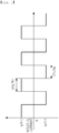
- FIG. 1 is a schematic diagram illustrating polarity fractions of arc welding current according to an embodiment of the present invention. As illustrated in FIG. 1 , welding polarity fractions may be appropriately mixed and altered to increase vibration of a molten pool due to an increase in arc pressure and droplet transfer frequency, to promote an increase in discharge of zinc vapor.
- the present invention in order to effectively discharge the zinc vapor from the molten pool when lap-joint welding a zinc coated steel sheet, it may be characterized by controlling a welding polarity fraction (EP R,% ) of a positive electrode of a welding wire and a welding polarity fraction (EN R,% ) of a negative electrode of a welding target base material by the above relationship 1 to be within an appropriate value, and introduction of this concept may be due to the following technical idea.
- DCEP direct current electrode positive
- a volume of a molten pool may increase due to an increase in heat input by to arc contraction, to reduce discharge of pores due to zinc vapor generated during welding.
- DCEN direct current negative
- arc contraction and oxygen atmosphere may increase so that the increase of the negative electrode activation of the wire in a DCEN cycle could be realized.
- occurrence of a cathode spot and arc concentration may be frequent on an upper end of the wire to heat the wire.
- a current path may be maintained in a subsequent DCEP cycle, and an arc may be generated on the upper end of the wire.
- globular and spray droplet transfer modes may occur to simultaneously increase droplet transfer frequency and arc pressure pressurization frequency, to maximize discharge of pores generated in the molten pool.
- an arc may be eccentric on the DCEN polarity due to influence of a zinc coated layer. Therefore, an effective arc radius may decrease as a cathode spot may be distributed over a wide area on a surface of the target base material, or the cathode spot may be concentrated on a specific region, to reduce welding heat input efficiency.
- an effective arc radius may decrease as a cathode spot may be distributed over a wide area on a surface of the target base material, or the cathode spot may be concentrated on a specific region, to reduce welding heat input efficiency.
- a fraction of the DCEN polarity is high, coarse and unstable globular transfer and arcs may occur, and an exposure time of the cathode spot to the droplet may increase. Therefore, since unstable and excessive spatter may be generated due to occurrence of a cathode jet on a surface of the droplet, arc instability and reduction in dischaging pores may appear.
- an adverse effect on suppressing the occurrence of porosity defects in the welded portion
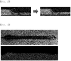
- FIG. 2 is a cross-sectional photograph of a welded bead before (Comparative Example 8) and after (Inventive Example 2) optimizing polarity fractions of arc welding current of a zinc coated steel sheet
- FIG. 3 is a photograph showing an appearance of a welded portion and results of X-ray transmission of the welded portion, after optimizing polarity fractions of arc welding current of a zinc coated steel sheet (welding rate of 100 cm/min)
- FIG. 4 is a graph illustrating results of measuring hardness of a welded portion, after optimizing polarity fractions of arc welding current of a zinc coated steel sheet of Inventive Example 2
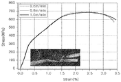
- FIG. 5 is a graph showing results of tensile curves of a welded portion, after optimizing polarity fractions of arc welding current of a zinc coated steel sheet of Inventive Example 2 of the present invention.
Landscapes
- Engineering & Computer Science (AREA)
- Physics & Mathematics (AREA)
- Plasma & Fusion (AREA)
- Mechanical Engineering (AREA)
- Chemical & Material Sciences (AREA)
- Materials Engineering (AREA)
- Arc Welding In General (AREA)
- Arc Welding Control (AREA)
Abstract
Description
- The present invention relates to a method for lap-joint welding a hot-dip galvanizing steel sheet having a tensile strength of 780 MPa or more and a thickness of 6 mm or less, applied to vehicle chassis components and the like, and relates to a method for lap-joint welding a hot-dip galvanizing steel sheet, controlling polarity of arc current to an appropriate fraction during welding, to effectively reduce porosity defects of a welded component up to 100 cm/min without introducing existing requirements such as providing a gap of an overlapped joint, changing an arc position, or the like, to improve strength of welded metal.
- In the automotive sector, research into technology to reduce the weight of vehicle bodies and components is emerging as a major issue, due to fuel economy regulation policies in accordance with environmental protection to, e.g., global warming or the like. Chassis components, which may be important for vehicle driving performance, are also required to apply a high-strength steel material for weight reduction in accordance with such trend. In order to achieve weight reduction of components, it may be essential to increase strength of a material, and it may be an important factor to guarantee durability of components made of the high-strength steel material in an environment in which repeated fatigue loads are applied. In the case of arc welding, mainly used to secure strength when assembling vehicle chassis components, since an overlapping joint welding process between components may be performed by deposition of welding wires, the high-strength steel material may be particularly important to secure strength of the welded metal. In addition, as described above, due to thinning of a material by trends following high strength and weight reduction of components, demand for rust resistance for prevention of penetration corrosion has increased, to increase adoption of a plated steel material. However, porosity defects may be sensitive, which may be a factor that lowers strength of a welded portion. In particular, the higher the strength of steel, the greater the concern that a welded metal may be damaged due to insufficient strength by porosity defects in the welded metal.
- Patent Document 1, a conventional patent, has proposed a gap of an overlapped joint in the range of 0.2 to 1.5mm in order to suppress occurrence of porosity defects in an arc welding portion of Zn-based zinc coated steel sheet. However, when an actual component is applied, there may be a limit that cannot guarantee welding properties of a joint structure not having a gap. In addition, in order to solve the above problem,
Patent Document 2 has proposed that a ternary shielding gas in which Ar is mixed with CO2 and O2 and a low-viscosity solid wire to which contents of Si, Mn, and the like are limited are applied, and arc positions are located to be spaced 1 mm apart from a tip of an overlapped joint. However, restrictions on a shielding gas and a welding material are inevitable, and there is a burden to maintain the arc positions constant when applying actual components. -
- (Patent Document 1)
Japanese Patent Laid-Open No. 2016-101593 - (Patent Document 2)
Japanese Patent Laid-Open No. 2015-167981 - An aspect of the present invention may provide a method for welding a zinc coated steel sheet, optimizing a polarity fraction of arc welding current to effectively reduce porosity defects in an welded portion when lap-joint welding zinc coated steel sheets, to provide a component welding portion of a zinc coated steel sheet having a tensile strength of 780 MPa or more and a thickness of 6 mm or less without welding requirements such as providing a gap of an overlapped joint, adjusting a width of the joint, changing an arc position, or the like.
- An aspect of the present invention relates to a method for lap-joint welding a zinc coated steel sheet using a welding wire, to reduce a porosity defect of welded metal, wherein, when welding, a welding current is 150 to 300 A, a shielding gas is a mixed gas of Ar + 10 to 30% CO2, and a welding polarity is alternately altered to satisfy a welding polarity fraction, defined by the following relationship 1, in a range of 0.25 to 0.35,

- In the method, the welding material may be an E70C-GS Φ1.0 metal cored wire.
- In the method, a gap of a welded joint formed by the method may be 0 mm.
- In the method, the welding current may be 200 to 270 A.
- In the method, the zinc coated steel sheet may be HGI 780HB steel.
- According to an aspect of the present invention, a polarity fraction of an arc welding current may be optimized to effectively reduce porosity defects in an overlapped joint welded portion without a gap of a joint, to effectively improve strength of a welded portion of a zinc coated steel sheet component having a tensile strength of 780 MPa or more, manufactured accordingly. Therefore, industrial significance capable of expanding adoption of zinc coated steel sheets for securing high strength of components such as vehicle chassis members and the like, and rust resistance due to thinning thereof may be provided.
-
-
FIG. 1 is a schematic diagram illustrating polarity fractions of arc welding currents according to an embodiment of the present invention. -
FIG. 2 is a cross-sectional photograph of a welded bead before and after optimizing polarity fractions of arc welding currents of a zinc coated steel sheet (where, a welding target base material, used, is HGI 780Hyber Burr having 2.0 mm thickness, a tensile strength of 810 MPa, and a plating amount on one side of 100 g/m2). -
FIG. 3 is a photograph showing an appearance of a welded portion and results of X-ray transmissions of the welded portion, after optimizing polarity fractions of arc welding current of a zinc coated steel sheet (a welding rate of 100 cm/min). -
FIG. 4 is a graph illustrating results of measuring hardness of a welded portion, after optimizing polarity fractions of arc welding current of a zinc coated steel sheet. -
FIG. 5 is a graph showing results of tensile curves of a welded portion, after optimizing polarity fractions of arc welding current of a zinc coated steel sheet. - Hereinafter, the present invention will be described.
- The inventors of the present invention confirmed that zinc vapor may be effectively discharged externally by optimally controlling polarity fractions of arc welding current when lap-joint welding a zinc coated steel sheet to vibrate a molten pool formed by welding, and porosity defects of a welded metal may be ultimately reduced, to complete the present invention.
- For example, a method for welding a zinc coated steel sheet of the present invention relates to a method for lap-joint welding a zinc coated steel sheet using a welding wire, wherein, when welding, a welding current is 150 to 300 A, a shielding gas is a mixed gas of Ar + 10 to 30% CO2, and a welding polarity is alternately altered to satisfy a welding polarity fraction, defined by the following relationship 1, in a range of 0.25 to 0.35.
- First, the present invention relates to a method for lap-joint welding a zinc coated steel sheet.
- The lap-joint welding method may refer to a method of welding a first zinc coated steel sheet and a second zinc coated steel sheet stacked to partially overlap the first zinc coated steel sheet, while forming a welded metal by an overlapping arc welding process.
- In the present invention, the zinc coated steel sheet may include a conventional hot-rolled or cold-rolled zinc coated steel sheet, and further, the coated steel sheet may be a Zn-Mg-Al-based alloy-plated steel sheet.
- In the present invention, a first zinc coated steel sheet and a second zinc coated steel sheet stacked to partially overlap the first zinc coated steel sheet may be joined to form a welded metal by an arc welding process. For example, after preparing the first zinc coated steel sheet and the second zinc coated steel sheet, a welding line may be formed by stacking the second plated steel sheet on the first plated steel sheet to partially overlap them. Then, welding current may be supplied to a welding wire while providing a shielding gas along the formed welding line, to generate an arc to proceed with the arc welding process.
- In the present invention, at this time, an overlapping width of a welded joint may be about 25 mm, when applied, but is not limited thereto.
- In addition, in the present invention, the welding wire may be an E70C-GS Φ1. 0 metal cored wire, and is not particularly limited to a type and a component of the welding wire.
- The welding current during welding is preferably limited to 150 A or more and 300 A or less, and more preferably limited to 200 A or more and 270 A or less. When the current is too low, an effect of discharging plating vapor may decrease due to reduction of arc force. When the current is too high, a molten welded metal portion may be unstable and occurrence of porosity defects may increase.
- In addition, in the present invention, it may be necessary to mix 10 to 30% CO2 with Ar as a shielding gas during welding. For example, the shield gas may be Ar gas, and may contain 10 to 30% of CO2 gas. When the CO2 gas is included in an amount less than 10%, an arc heat pinch force effect may decrease due to arc expansion to reduce a plating vapor discharge effect. In addition, when the CO2 gas is included in an amount exceeding 30%, the arc heat pinch force effect may excessively increase due to arc contraction to reduce the plating vapor discharging effect.
- In addition, in the present invention, during the arc welding, a welding torch angle in the range of 30 to 45° and a progress angle in the range of 0 to 25° may be managed.
- In addition, in the present invention, a gap of a welded joint formed 0 mm may be applied, but is not particularly limited thereto.
- In lap-joint welding a zinc coated steel sheet, during arc welding, a zinc coated layer having a low boiling point may become zinc gas due to arc heat, and may float to an upper portion of a molten pool. In this case, most thereof may be discharged, but a portion thereof may remain to form a blowhole, which may be a hollow cavity when solidified. Therefore, there may be problems in that a welded metal manufactured by welding has porosity defects, and thus, a welded metal having excellent tensile strength cannot be obtained.
- Therefore, the present invention may be provided to solve the problems, and may be characterized in that a welding polarity is alternately altered to satisfy a welding polarity fraction, defined by the following relationship 1, in a range of 0.25 to 0.35. Thereby, a molten pool formed by welding may be vibrated to discharge zinc vapor, to reduce a porosity defect of welded metal.

-
FIG. 1 is a schematic diagram illustrating polarity fractions of arc welding current according to an embodiment of the present invention. As illustrated inFIG. 1 , welding polarity fractions may be appropriately mixed and altered to increase vibration of a molten pool due to an increase in arc pressure and droplet transfer frequency, to promote an increase in discharge of zinc vapor. - In the present invention, in order to effectively discharge the zinc vapor from the molten pool when lap-joint welding a zinc coated steel sheet, it may be characterized by controlling a welding polarity fraction (EPR,%) of a positive electrode of a welding wire and a welding polarity fraction (ENR,%) of a negative electrode of a welding target base material by the above relationship 1 to be within an appropriate value, and introduction of this concept may be due to the following technical idea.
- In a general case of a direct current electrode positive (DCEP) pulse, there may be a limitation in that a volume of a molten pool may increase due to an increase in heat input by to arc contraction, to reduce discharge of pores due to zinc vapor generated during welding. In contrast, when a DCEP and a direct current negative (DCEN) polarity are mixed in an appropriate fraction and altered, arc contraction and oxygen atmosphere may increase so that the increase of the negative electrode activation of the wire in a DCEN cycle could be realized. For example, during the DCEN cycle, occurrence of a cathode spot and arc concentration may be frequent on an upper end of the wire to heat the wire. Then, a current path may be maintained in a subsequent DCEP cycle, and an arc may be generated on the upper end of the wire. At this time, globular and spray droplet transfer modes may occur to simultaneously increase droplet transfer frequency and arc pressure pressurization frequency, to maximize discharge of pores generated in the molten pool.
- Therefore, in the case of a variable polarity arc, since the arc pressure and the droplet transfer may be irregular and high frequency, an effect of discharging the pores may be excellent. When a fraction of the DCEN polarity is lower than an appropriate value, the effect may be reduced when a value defined by the above relationship 1 is less than 0.25.
- In the case of a zinc coated steel sheet such as HGI, an arc may be eccentric on the DCEN polarity due to influence of a zinc coated layer. Therefore, an effective arc radius may decrease as a cathode spot may be distributed over a wide area on a surface of the target base material, or the cathode spot may be concentrated on a specific region, to reduce welding heat input efficiency. In addition, when a fraction of the DCEN polarity is high, coarse and unstable globular transfer and arcs may occur, and an exposure time of the cathode spot to the droplet may increase. Therefore, since unstable and excessive spatter may be generated due to occurrence of a cathode jet on a surface of the droplet, arc instability and reduction in dischaging pores may appear. For example, when a fraction of the DCEN polarity exceeds the appropriate value (when a value defined by the relationship 1 exceeds 0.35), an adverse effect on suppressing the occurrence of porosity defects in the welded portion may occur.
- Hereinafter, the present invention will be described in detail through examples.
- Two (2) HGI 780Hyber Burring steel sheets having 2.0 mm thickness and a plating amount on one side of 100g/m2 were made to overlap each other by 25 mm, and a connection portion therebetween was welded. Specifically, welding wires and welding conditions were used as shown in Tables 1 and 2, respectively, the HGI 780HB steel was lap-joint welded. At this time, the presence or absence of pit generation and pore area ratios were measured and shown in Table 1 below, and tensile strengths and fracture positions of welded portions were measured and shown in Table 2 below.
[Table 1] No. Welding Material Welding Conditions (Current-Voltage-Rate) Current Properties Pit Pore Area Ratios Example 1 EK70S-6Φ1.2 202A-20.6V-0.6m/min EP:EN=100:0 X 1.55% CE1 2 EK70S-6Φ1.2 242A-23.7V-0.8m/min EP:EN=100:0, Pulse O 12.67% CE2 3 EK70S-6Φ1.2 263A-23.6V-1.0m/min EP:EN=100:0, Pulse O 20.60% CE3 4 ER70S-3Φ1.0 162A-26.4V-0.6m/min EP:EN=100:0, Pulse X 4.46% CE4 5 ER70S-3Φ1.0 217A-28.9V-0.8m/min EP:EN=100:0, Pulse X 5.70% CE5 6 ER70S-3Φ1.0 237A-30.0V-1.0m/min EP:EN=100:0, Pulse O 8.25% CE6 7 E70C-GSΦ1.0 214A-24.0V-1.0m/min EP:EN=50:50, Pulse X 2.51% CE7 8 E70C-GSΦ1.0 213A-24.0V-1.0m/min EP:EN=60:40, Pulse X 2.34% CE8 9 E70C-GSΦ1.0 214A-24.0V-1.0m/min EP:EN=65:35, Pulse X 0.97% IE1 10 E70C-GSΦ1.0 209A-24.0V-1.0m/min EP:EN=70:30, Pulse X 0.87% IE2 11 E70C-GSΦ1.0 216A-24.2V-1.0m/min EP:EN=75:25, Pulse X 0.94% IE3 12 E70C-GSΦ1.0 210A-24.0V-1.0m/min EP:EN=80:20, Pulse X 1.52% CE9 *IE: Inventive Example, **CE: Comparative Example [Table 2] No. Welding Material Welding Conditions (Current-Voltage-Rate) Current Properties Tensile Strength Fracture Position Examp le 1 EK70S-6Φ1.2 202A-20.6V-0.6m/min EP:EN=100:0 625 MPa Welded Metal CE1 2 EK70S-6Φ1.2 242A-23.7V-0.8m/min EP:EN=100:0, Pulse 599 MPa Welded Metal CE2 3 EK70S-6Φ1.2 263A-23.6V-1.0m/min EP:EN=100:0, Pulse 473 MPa Welded Metal CE3 4 ER70S-3Φ1.0 162A-26.4V-0.6m/min EP:EN=100:0, Pulse 690 MPa Heat Affected Zone CE4 5 ER70S-3Φ1.0 217A-28.9V-0.8m/min EP:EN=100:0, Pulse 678 MPa Heat Affected Zone CE5 6 ER70S-3Φ1.0 257A-30.0V-1.0m/min EP:EN=100:0, Pulse 670 MPa Heat Affected Zone CE6 7 E70C-GSΦ1.0 214A-24.0V-1.0m/min EP:EN=50:50, Pulse 692 MPa Heat Affected Zone CE7 8 E70C-GSΦ1.0 213A-24.0V-1.0m/min EP:EN=60:40, Pulse 696 MPa Heat Affected Zone CE8 9 E70C-GSΦ1.0 214A-24.0V-1.0m/min EP:EN=65:35, Pulse 700 MPa Heat Affected Zone IE1 10 E70C-GSΦ1.0 209A-24.0V-1.0m/min EP:EN=70:30, Pulse 702 MPa Heat Affected Zone IE2 11 E70C-GSΦ1.0 216A-24.2V-1.0m/min EP:EN=75:25, Pulse 701 MPa Heat Affected Zone IE3 12 E70C-GSΦ1.0 213A-24.0V-1.0m/min EP:EN=80:20, Pulse 698 MPa Heat Affected Zone CE9 *IE: Inventive Example, **CE: Comparative Example - As shown in Tables 1 and 2, it can be seen that Inventive Examples 1 to 3 in which polarity fraction values defined by the relationship 1 satisfy the range of 0.25 to 0.35 and as well as welding conditions such as welding current and the like satisfy a given range had reduced effect of discharging zinc vapor to reduce porosity defects in a welded portion and improved a tensile strength of the welded portion, as compared to Comparative Examples 1 to 8 in which the polarity fraction values and the welding conditions do not.
-
FIG. 2 is a cross-sectional photograph of a welded bead before (Comparative Example 8) and after (Inventive Example 2) optimizing polarity fractions of arc welding current of a zinc coated steel sheet, andFIG. 3 is a photograph showing an appearance of a welded portion and results of X-ray transmission of the welded portion, after optimizing polarity fractions of arc welding current of a zinc coated steel sheet (welding rate of 100 cm/min), andFIG. 4 is a graph illustrating results of measuring hardness of a welded portion, after optimizing polarity fractions of arc welding current of a zinc coated steel sheet of Inventive Example 2, andFIG. 5 is a graph showing results of tensile curves of a welded portion, after optimizing polarity fractions of arc welding current of a zinc coated steel sheet of Inventive Example 2 of the present invention. - As can be seen in
FIGS. 4 and5 , even at a welding rate of 100 cm/min, a hardness value of a welded metal portion was quite constant without a significant decrease due to porosity defects. In addition, it can be seen as a result of suppressing occurrence of porosity defects in the welded metal due to fracture in heat affected zones without fracture of the welded metal portions. - While example embodiments have been shown and described above, it will be apparent to those skilled in the art that modifications and variations could be made without departing from the scope of the present invention as defined by the appended claims.
Claims (5)
- A method for lap-joint welding a zinc coated steel sheet using a welding wire, to reduce a porosity defect of welded metal,
wherein, when welding, a welding current is 150 to 300 A, a shielding gas is a mixed gas of Ar + 10 to 30% CO2, and a welding polarity is alternately altered to satisfy a welding polarity fraction, defined by the following relationship 1, in a range of 0.25 to 0.35.
- The method of claim 1, wherein the welding wire is an E70C-GS Φ1.0 metal cored wire.
- The method of claim 1, wherein a gap of a welded joint formed by the method is 0 mm.
- The method of claim 1, wherein the welding current is 200 to 270 A.
- The method of claim 1, wherein the zinc coated steel sheet is HGI 780HB steel.
Applications Claiming Priority (2)
| Application Number | Priority Date | Filing Date | Title |
|---|---|---|---|
| KR1020180129810A KR102119964B1 (en) | 2018-10-29 | 2018-10-29 | Method for welding a zinc coated steel sheet |
| PCT/KR2019/013207 WO2020091254A1 (en) | 2018-10-29 | 2019-10-08 | Method for welding a zinc coated steel sheet |
Publications (4)
| Publication Number | Publication Date |
|---|---|
| EP3875205A1 true EP3875205A1 (en) | 2021-09-08 |
| EP3875205A4 EP3875205A4 (en) | 2022-01-12 |
| EP3875205C0 EP3875205C0 (en) | 2025-08-06 |
| EP3875205B1 EP3875205B1 (en) | 2025-08-06 |
Family
ID=70462601
Family Applications (1)
| Application Number | Title | Priority Date | Filing Date |
|---|---|---|---|
| EP19879821.7A Active EP3875205B1 (en) | 2018-10-29 | 2019-10-08 | Method for welding a zinc coated steel sheet |
Country Status (7)
| Country | Link |
|---|---|
| US (1) | US12459049B2 (en) |
| EP (1) | EP3875205B1 (en) |
| JP (1) | JP7190562B2 (en) |
| KR (1) | KR102119964B1 (en) |
| CN (1) | CN112930239A (en) |
| MX (1) | MX2021004206A (en) |
| WO (1) | WO2020091254A1 (en) |
Family Cites Families (26)
| Publication number | Priority date | Publication date | Assignee | Title |
|---|---|---|---|---|
| JPH079150A (en) | 1993-06-23 | 1995-01-13 | Matsushita Electric Ind Co Ltd | Gas shield arc welding method for galvanized steel sheet and galvanized steel sheet products welded by the welding method |
| JPH11138265A (en) * | 1997-10-31 | 1999-05-25 | Daihen Corp | Dc pulsed mag welding method and its equipment |
| JP2003334657A (en) | 2002-05-20 | 2003-11-25 | Daihen Corp | Arc spot welding method for galvanized steel sheet lap joints |
| JP4657588B2 (en) | 2003-07-09 | 2011-03-23 | 株式会社ダイヘン | Current control method for AC TIG welding |
| JP4622305B2 (en) | 2004-05-14 | 2011-02-02 | トヨタ自動車株式会社 | Method of lap fusion welding of Zn-plated steel sheet and Fe-based filler material |
| JP2008018436A (en) * | 2006-07-11 | 2008-01-31 | Yorozu Corp | Welding method and weldment |
| JP5358844B2 (en) | 2009-05-15 | 2013-12-04 | 株式会社安川電機 | Arc welding method |
| KR101091318B1 (en) | 2009-07-21 | 2011-12-07 | 주식회사 포스코 | Overlap Welding of Plating Materials |
| JP5287656B2 (en) | 2009-10-27 | 2013-09-11 | 新日鐵住金株式会社 | Method of lap fillet arc welding of galvanized steel sheet and lap fillet arc welded joint |
| CN102470474B (en) * | 2010-02-23 | 2015-07-08 | 松下电器产业株式会社 | AC arc welding method and AC arc welding device |
| JP2012101232A (en) * | 2010-11-08 | 2012-05-31 | Nippon Steel Corp | Fillet arc welding method of galvanized steel sheet |
| JP2012183542A (en) * | 2011-03-03 | 2012-09-27 | Nippon Steel Corp | Fillet arc welding method of steel plate |
| US20130001210A1 (en) | 2011-07-01 | 2013-01-03 | Illinois Tool Works Inc. | Metal cored welding method and system |
| JP2013063460A (en) | 2011-09-20 | 2013-04-11 | Nippon Steel & Sumikin Welding Co Ltd | Arc spot welding method for lap joint of galvanized steel sheet |
| JP5541263B2 (en) * | 2011-11-04 | 2014-07-09 | Jfeスチール株式会社 | High-strength hot-rolled steel sheet excellent in workability and manufacturing method thereof |
| US10543556B2 (en) | 2012-08-28 | 2020-01-28 | Hobart Brothers Llc | Systems and methods for welding zinc-coated workpieces |
| JP2014061526A (en) | 2012-09-20 | 2014-04-10 | Daihen Corp | Protection control method of welding device |
| FR3009506B1 (en) | 2013-08-07 | 2016-02-05 | Peugeot Citroen Automobiles Sa | METHOD FOR WELDING TOGETHER THE TWO SUPERPOSED EDGES OF TWO SHEETS OF GALVANIZED STEEL OR ALUMINUM |
| EP3055101A2 (en) * | 2013-10-09 | 2016-08-17 | Hobart Brothers Company | Systems and methods for corrosion-resistant welding electrodes |
| JP5968934B2 (en) | 2014-03-07 | 2016-08-10 | 大陽日酸株式会社 | Welding method of galvanized steel sheet |
| US10052707B2 (en) | 2014-04-04 | 2018-08-21 | Lincoln Global, Inc. | Method and system to use AC welding waveform and enhanced consumable to improve welding of galvanized workpiece |
| KR101637656B1 (en) | 2014-06-19 | 2016-07-07 | 현대자동차주식회사 | Welding method for plating steel sheet |
| JP6023156B2 (en) | 2014-11-27 | 2016-11-09 | 日新製鋼株式会社 | Arc welding method for Zn-plated steel sheet |
| US10179369B2 (en) | 2015-10-27 | 2019-01-15 | Lincoln Global, Inc. | Welding system for AC welding with reduced spatter |
| JP6385411B2 (en) * | 2016-10-28 | 2018-09-05 | 日新製鋼株式会社 | Welded member and manufacturing method thereof |
| KR102020515B1 (en) * | 2016-12-23 | 2019-09-11 | 주식회사 포스코 | Welded member having excellent welded portion porosity resistance and fatigue property and method of manufacturing the same |
-
2018
- 2018-10-29 KR KR1020180129810A patent/KR102119964B1/en active Active
-
2019
- 2019-10-08 MX MX2021004206A patent/MX2021004206A/en unknown
- 2019-10-08 EP EP19879821.7A patent/EP3875205B1/en active Active
- 2019-10-08 WO PCT/KR2019/013207 patent/WO2020091254A1/en not_active Ceased
- 2019-10-08 US US17/289,537 patent/US12459049B2/en active Active
- 2019-10-08 JP JP2021518922A patent/JP7190562B2/en active Active
- 2019-10-08 CN CN201980071010.5A patent/CN112930239A/en active Pending
Also Published As
| Publication number | Publication date |
|---|---|
| EP3875205C0 (en) | 2025-08-06 |
| MX2021004206A (en) | 2021-05-27 |
| US20210394294A1 (en) | 2021-12-23 |
| CN112930239A (en) | 2021-06-08 |
| KR20200048105A (en) | 2020-05-08 |
| US12459049B2 (en) | 2025-11-04 |
| JP2022502264A (en) | 2022-01-11 |
| KR102119964B1 (en) | 2020-06-05 |
| WO2020091254A1 (en) | 2020-05-07 |
| JP7190562B2 (en) | 2022-12-15 |
| EP3875205B1 (en) | 2025-08-06 |
Similar Documents
| Publication | Publication Date | Title |
|---|---|---|
| CN111230301B (en) | Method of manufacturing thin-wall welded and other strong parts of steel with aluminum or aluminum alloy coating | |
| EP3815837A1 (en) | Different-strength steel welding component with aluminum or aluminum-alloy plating and method for manufacturing same | |
| CN110337344B (en) | Overlap fillet arc welding head and manufacturing method thereof | |
| KR101639905B1 (en) | Welding member having excellent welded portion fatigue characteristic and method for manufacturing the same | |
| EP3351333A1 (en) | Fillet welding method and fillet welded joint | |
| WO2015186544A1 (en) | Vertical narrow gap gas shielded arc welding method | |
| WO2022230903A1 (en) | Arc welded joint and arc welding method | |
| KR102020515B1 (en) | Welded member having excellent welded portion porosity resistance and fatigue property and method of manufacturing the same | |
| EP3808488B1 (en) | Plated steel sheet weld member having excellent porosity-resistance and fatigue property of weld zone, and method for manufacturing same | |
| EP4306255A1 (en) | Arc-welded joint and arc-welding method | |
| EP3875205B1 (en) | Method for welding a zinc coated steel sheet | |
| JP5280060B2 (en) | Gas shield arc welding method | |
| JP2020157358A (en) | Spot welding method of galvanized steel plate | |
| KR102386730B1 (en) | Method for resistance spot welding of ultra-high strength steel | |
| KR20150145479A (en) | Welding method for plating steel sheet | |
| US11815127B2 (en) | Welded member for plated steel plate excellent in weld zone porosity resistance and fatigue properties and method for manufacturing the same | |
| JP2000015353A (en) | Welded metal sheet excellent in press formability and method for producing the same | |
| JP2023515843A (en) | Welding wire capable of obtaining giga-class welds, welded structure manufactured using the same, and welding method thereof | |
| EP4306254A1 (en) | Arc-welded joint and arc-welding method | |
| EP4537974A1 (en) | Welding member having welding portion having excellent fatigue properties | |
| WO2020054717A1 (en) | Method for producing vertical narrow-groove welding joint, and vertical narrow-groove welding joint | |
| KR20250091579A (en) | Method for resistance spot welding of hot press formed member | |
| JP6119949B1 (en) | Vertical narrow groove gas shielded arc welding method | |
| KR20250091772A (en) | Method for resistance spot welding of hot press formed member | |
| KR20160035270A (en) | Electrogas Welding Method |
Legal Events
| Date | Code | Title | Description |
|---|---|---|---|
| STAA | Information on the status of an ep patent application or granted ep patent |
Free format text: STATUS: THE INTERNATIONAL PUBLICATION HAS BEEN MADE |
|
| PUAI | Public reference made under article 153(3) epc to a published international application that has entered the european phase |
Free format text: ORIGINAL CODE: 0009012 |
|
| STAA | Information on the status of an ep patent application or granted ep patent |
Free format text: STATUS: REQUEST FOR EXAMINATION WAS MADE |
|
| 17P | Request for examination filed |
Effective date: 20210519 |
|
| AK | Designated contracting states |
Kind code of ref document: A1 Designated state(s): AL AT BE BG CH CY CZ DE DK EE ES FI FR GB GR HR HU IE IS IT LI LT LU LV MC MK MT NL NO PL PT RO RS SE SI SK SM TR |
|
| A4 | Supplementary search report drawn up and despatched |
Effective date: 20211213 |
|
| RIC1 | Information provided on ipc code assigned before grant |
Ipc: B23K 101/34 20060101ALI20211207BHEP Ipc: B23K 101/18 20060101ALI20211207BHEP Ipc: B23K 9/16 20060101ALI20211207BHEP Ipc: B23K 9/10 20060101ALI20211207BHEP Ipc: B23K 9/095 20060101ALI20211207BHEP Ipc: B23K 9/23 20060101AFI20211207BHEP |
|
| DAV | Request for validation of the european patent (deleted) | ||
| DAX | Request for extension of the european patent (deleted) | ||
| RAP3 | Party data changed (applicant data changed or rights of an application transferred) |
Owner name: POSCO HOLDINGS INC. |
|
| RAP1 | Party data changed (applicant data changed or rights of an application transferred) |
Owner name: POSCO CO., LTD |
|
| GRAP | Despatch of communication of intention to grant a patent |
Free format text: ORIGINAL CODE: EPIDOSNIGR1 |
|
| STAA | Information on the status of an ep patent application or granted ep patent |
Free format text: STATUS: GRANT OF PATENT IS INTENDED |
|
| INTG | Intention to grant announced |
Effective date: 20240426 |
|
| GRAJ | Information related to disapproval of communication of intention to grant by the applicant or resumption of examination proceedings by the epo deleted |
Free format text: ORIGINAL CODE: EPIDOSDIGR1 |
|
| STAA | Information on the status of an ep patent application or granted ep patent |
Free format text: STATUS: REQUEST FOR EXAMINATION WAS MADE |
|
| STAA | Information on the status of an ep patent application or granted ep patent |
Free format text: STATUS: EXAMINATION IS IN PROGRESS |
|
| INTC | Intention to grant announced (deleted) | ||
| 17Q | First examination report despatched |
Effective date: 20240715 |
|
| GRAP | Despatch of communication of intention to grant a patent |
Free format text: ORIGINAL CODE: EPIDOSNIGR1 |
|
| STAA | Information on the status of an ep patent application or granted ep patent |
Free format text: STATUS: GRANT OF PATENT IS INTENDED |
|
| INTG | Intention to grant announced |
Effective date: 20250312 |
|
| GRAS | Grant fee paid |
Free format text: ORIGINAL CODE: EPIDOSNIGR3 |
|
| GRAA | (expected) grant |
Free format text: ORIGINAL CODE: 0009210 |
|
| STAA | Information on the status of an ep patent application or granted ep patent |
Free format text: STATUS: THE PATENT HAS BEEN GRANTED |
|
| AK | Designated contracting states |
Kind code of ref document: B1 Designated state(s): AL AT BE BG CH CY CZ DE DK EE ES FI FR GB GR HR HU IE IS IT LI LT LU LV MC MK MT NL NO PL PT RO RS SE SI SK SM TR |
|
| REG | Reference to a national code |
Ref country code: GB Ref legal event code: FG4D |
|
| REG | Reference to a national code |
Ref country code: CH Ref legal event code: EP |
|
| REG | Reference to a national code |
Ref country code: IE Ref legal event code: FG4D |
|
| REG | Reference to a national code |
Ref country code: DE Ref legal event code: R096 Ref document number: 602019073873 Country of ref document: DE |
|
| U01 | Request for unitary effect filed |
Effective date: 20250901 |
|
| U07 | Unitary effect registered |
Designated state(s): AT BE BG DE DK EE FI FR IT LT LU LV MT NL PT RO SE SI Effective date: 20250905 |
|
| U20 | Renewal fee for the european patent with unitary effect paid |
Year of fee payment: 7 Effective date: 20251030 |
|
| PG25 | Lapsed in a contracting state [announced via postgrant information from national office to epo] |
Ref country code: IS Free format text: LAPSE BECAUSE OF FAILURE TO SUBMIT A TRANSLATION OF THE DESCRIPTION OR TO PAY THE FEE WITHIN THE PRESCRIBED TIME-LIMIT Effective date: 20251206 |
|
| PG25 | Lapsed in a contracting state [announced via postgrant information from national office to epo] |
Ref country code: NO Free format text: LAPSE BECAUSE OF FAILURE TO SUBMIT A TRANSLATION OF THE DESCRIPTION OR TO PAY THE FEE WITHIN THE PRESCRIBED TIME-LIMIT Effective date: 20251106 |
|
| PG25 | Lapsed in a contracting state [announced via postgrant information from national office to epo] |
Ref country code: HR Free format text: LAPSE BECAUSE OF FAILURE TO SUBMIT A TRANSLATION OF THE DESCRIPTION OR TO PAY THE FEE WITHIN THE PRESCRIBED TIME-LIMIT Effective date: 20250806 |
|
| PG25 | Lapsed in a contracting state [announced via postgrant information from national office to epo] |
Ref country code: GR Free format text: LAPSE BECAUSE OF FAILURE TO SUBMIT A TRANSLATION OF THE DESCRIPTION OR TO PAY THE FEE WITHIN THE PRESCRIBED TIME-LIMIT Effective date: 20251107 |
|
| PG25 | Lapsed in a contracting state [announced via postgrant information from national office to epo] |
Ref country code: PL Free format text: LAPSE BECAUSE OF FAILURE TO SUBMIT A TRANSLATION OF THE DESCRIPTION OR TO PAY THE FEE WITHIN THE PRESCRIBED TIME-LIMIT Effective date: 20250806 |
|
| PG25 | Lapsed in a contracting state [announced via postgrant information from national office to epo] |
Ref country code: RS Free format text: LAPSE BECAUSE OF FAILURE TO SUBMIT A TRANSLATION OF THE DESCRIPTION OR TO PAY THE FEE WITHIN THE PRESCRIBED TIME-LIMIT Effective date: 20251106 |
|
| PG25 | Lapsed in a contracting state [announced via postgrant information from national office to epo] |
Ref country code: ES Free format text: LAPSE BECAUSE OF FAILURE TO SUBMIT A TRANSLATION OF THE DESCRIPTION OR TO PAY THE FEE WITHIN THE PRESCRIBED TIME-LIMIT Effective date: 20250806 |
|
| PG25 | Lapsed in a contracting state [announced via postgrant information from national office to epo] |
Ref country code: SM Free format text: LAPSE BECAUSE OF FAILURE TO SUBMIT A TRANSLATION OF THE DESCRIPTION OR TO PAY THE FEE WITHIN THE PRESCRIBED TIME-LIMIT Effective date: 20250806 |
|
| PG25 | Lapsed in a contracting state [announced via postgrant information from national office to epo] |
Ref country code: CZ Free format text: LAPSE BECAUSE OF FAILURE TO SUBMIT A TRANSLATION OF THE DESCRIPTION OR TO PAY THE FEE WITHIN THE PRESCRIBED TIME-LIMIT Effective date: 20250806 |
|
| PG25 | Lapsed in a contracting state [announced via postgrant information from national office to epo] |
Ref country code: SK Free format text: LAPSE BECAUSE OF FAILURE TO SUBMIT A TRANSLATION OF THE DESCRIPTION OR TO PAY THE FEE WITHIN THE PRESCRIBED TIME-LIMIT Effective date: 20250806 |