EP3874927A1 - Verfahren zum erkennen von feldgrenzen - Google Patents
Verfahren zum erkennen von feldgrenzen Download PDFInfo
- Publication number
- EP3874927A1 EP3874927A1 EP20212247.9A EP20212247A EP3874927A1 EP 3874927 A1 EP3874927 A1 EP 3874927A1 EP 20212247 A EP20212247 A EP 20212247A EP 3874927 A1 EP3874927 A1 EP 3874927A1
- Authority
- EP
- European Patent Office
- Prior art keywords
- field
- position fixes
- route
- sections
- area
- Prior art date
- Legal status (The legal status is an assumption and is not a legal conclusion. Google has not performed a legal analysis and makes no representation as to the accuracy of the status listed.)
- Granted
Links
Images



Classifications
-
- A—HUMAN NECESSITIES
- A01—AGRICULTURE; FORESTRY; ANIMAL HUSBANDRY; HUNTING; TRAPPING; FISHING
- A01B—SOIL WORKING IN AGRICULTURE OR FORESTRY; PARTS, DETAILS, OR ACCESSORIES OF AGRICULTURAL MACHINES OR IMPLEMENTS, IN GENERAL
- A01B79/00—Methods for working soil
- A01B79/005—Precision agriculture
-
- A—HUMAN NECESSITIES
- A01—AGRICULTURE; FORESTRY; ANIMAL HUSBANDRY; HUNTING; TRAPPING; FISHING
- A01B—SOIL WORKING IN AGRICULTURE OR FORESTRY; PARTS, DETAILS, OR ACCESSORIES OF AGRICULTURAL MACHINES OR IMPLEMENTS, IN GENERAL
- A01B69/00—Steering of agricultural machines or implements; Guiding agricultural machines or implements on a desired track
- A01B69/007—Steering or guiding of agricultural vehicles, e.g. steering of the tractor to keep the plough in the furrow
- A01B69/008—Steering or guiding of agricultural vehicles, e.g. steering of the tractor to keep the plough in the furrow automatic
Definitions
- the invention relates to a method for recognizing field boundaries.
- the disadvantage of the known method is that only parts of the field on which work is carried out are recognized as belonging to the field. Often, however, a field also includes areas in which no field work is performed. Such areas include field parts in which the work machine is driven without doing work.
- step a) successive position fixes can be recognized via the time stamp.
- a position fix indicates a position at a specific point in time and can, for example, come from a satellite navigation system (GNSS for short) such as GPS or Galileo.
- GNSS satellite navigation system
- route sections are checked for parallelism in step b).
- the direction of travel which results from the chronological order of the fixed positions along the route section, is not relevant.
- Route sections running in parallel are combined into one area. This makes sense because agricultural work is often carried out along parallel routes.
- the areas each correspond to a worked inner field or a headland.
- step a) and d) are lengthened in step c) and a check is made in step d) to determine whether the lengthening is in a different area. If this is the case, in step e) the area in which the extended route section belongs is added to the area to which the route section belongs. This is advantageous because the extension of a straight stretch of road in the worked inner field is often in the headland. Steps c), d) and e) combine the inner field and the headland.
- a closed field boundary is determined around the area summarized in this way.
- At least one outer field boundary is determined and optionally one or more inner field boundaries.
- Inner field boundaries arise, for example, when a field encloses an obstacle such as trees, rocks or ponds.
- the position fixes were received by a single work machine. This ensures that position fixes from different machines working in one field or adjacent fields are not mixed up.
- the position fixes are assigned an identification feature of the work machine. With the help of the identification feature, the fixed positions of different machines can be distinguished. This means that the straight sections of the route for the individual machines can be recorded separately.
- Overlapping areas that have been processed by different machines can be combined into one area. This can be done automatically, for example if the overlap exceeds a predetermined size. It is also possible to combine several machines manually.
- three temporally successive position fixes belong to a straight route section if the two vectors between each two temporally successive position fixes enclose an angle below a predetermined maximum angle.
- the maximum angle is preferably less than 20 °, particularly preferably less than 10 °.
- the maximum angle is preferably chosen not to be too small, since deviations can also arise, for example, due to inaccuracies in the detection of the fixed positions. Slight curves are also possible during field work. Tight bends, on the other hand, are a sign of turning maneuvers and driving on the road.
- step b) only parallel route sections are combined into areas whose normal distance does not exceed a limit value.
- the limit value is a maximum working width. Coincidentally parallel road sections at a large distance are not combined into areas.
- the limit value can, for example, be assigned to an identification feature of the work machine. Alternatively, the limit value can be specified manually.
- the areas are divided into an inner field and headland.
- the subdivision can take place, for example, on the properties of the parallel route sections.
- An inner field is often driven on with an even distance between the road sections, while this is not the case in the headland.
- other data linked to the position fixes can be used for the classification.
- step c) the route sections are lengthened by a value that depends on the distance between two fixed positions on the route section. The greater the distance between two position fixes, the greater the value. The distance between the position fixes depends on the measuring interval of the position fixes and the travel speed of the machine.
- the working width is determined from the normal distance between the parallel route sections and the field boundary is enlarged by half a working width. This takes into account the fact that the satellite navigation receiver is usually in the center of the vehicle within the working width of the vehicle.
- the field boundaries are enlarged by a predetermined value and then reduced by the same value.
- the enlargement makes it possible to close gaps within the field that can arise, for example, due to random fluctuations in the determination of the position fixes. If you then zoom out, these gaps will not be reopened. Enlarging and reducing the field boundaries thus enables the simple elimination of gaps within fields that have arisen due to measurement errors.
- the fixed positions are compared with a map before step a) and fixed positions which are essentially located on a street are not taken into account in the method steps. By comparing them with the map, points that lie on a road running parallel to the edge of the field can easily be excluded from the process.
- further data linked to the fixed position are available for each fixed position, the linked data being used to determine whether field work was carried out on the fixed position and only in the process steps Position fixes are processed on which field work has been carried out.
- the linked data can, for example, be information about the status of the work machine at the time the position fix was determined.
- the data are preferably linked to the fixed positions on the work machine and stored together with the fixed positions and / or sent to a central computer.
- the data and the position fixes can each be provided with a time stamp and linked during the method according to the invention.
- the linked data include the power requirement of the work machine, settings of work units of the work machine and / or measured values from sensors of the work machine. It is very likely that the data will show whether field work has been carried out.
- Figure 1 a plurality of position fixes 1 of a work machine are shown. Before the actual analysis, the fixed positions 1 are compared with a map and the fixed positions 1, which are essentially located on a street 2, are not taken into account in the analysis. The other position fixes 1 are analyzed for straight route sections 3. A route section is regarded as an essentially straight line if a sequence of position fixes 1 does not have an angle above a maximum angle.
- areas 6, 7, 8, which are likely to be in the same field are combined.
- the straight sections of an area 6 are extended in a straight line.
- the value of the lengthening preferably depends on the distance between the position fixes 1.
- the distance between the position fixes 1 in turn depends on the driving speed of the work machine during the recording of the position fixes 1 and the recording interval, that is, the time interval between the position fixes 1. If an extension overlaps with another area 7, then this area is probably in the same field as the extended route section 6.
- Route sections 3 which are located in an inner field 6 are preferably extended. Extensions of route sections of an inner field 6 often overlap with areas that represent headlands 7.
- the areas 6, 7 are then combined into one field.
- the field boundaries 12, 13 are then determined for the fields 10, 11 determined in this way.
- the mean value of the normal distances 9 is determined for the fields. This corresponds to the working width.
- the field boundary 12, 13 is half a working width outside the outermost route section.
- Field boundaries 12 inside fields 11 can arise from areas in which the work machine was not, from areas in which no position fix 1 could be determined or from measurement errors when determining position fixes 1. In the first case, the inner field boundary 12 is correctly determined been. Cases in which it was not possible to determine a position fix 1 can be recognized by an unusually large distance between position fixes and the gap can be counted in field 11.
- the field boundaries 12, 13 are enlarged to eliminate gaps that have arisen due to measurement errors when determining the position fixes 1. By the enlargement, gaps are closed and inner field boundaries 12 disappear. The field boundaries 12, 13 are then reduced by the same value. In Figure 5 two fields 10, 11 are shown with closed gaps. Outer field boundaries 13 and correct inner field boundaries 12 remain unchanged by this method.
Landscapes
- Life Sciences & Earth Sciences (AREA)
- Engineering & Computer Science (AREA)
- Mechanical Engineering (AREA)
- Soil Sciences (AREA)
- Environmental Sciences (AREA)
- Control Of Position, Course, Altitude, Or Attitude Of Moving Bodies (AREA)
Abstract
a) Analysieren einer Vielzahl von Positionsfixen (1) einer Arbeitsmaschine und zugehörigen Zeitstempeln auf im Wesentlichen gerade Streckenabschnitte (3, 4, 5),
b) Zusammenfassen von parallelen Streckenabschnitten (3, 4, 5) zu Gebieten (6, 7, 8),
c) Verlängern der geraden Streckenabschnitte (3, 4, 5),
d) prüfen ob ein verlängerter Streckenabschnitt (3, 4, 5) in einem anderen Gebiet (6, 7, 8) liegt,
e) Zusammenfassen des Gebietes (6, 7, 8) in dem der verlängerte Streckenabschnitt liegt mit dem Gebiet (6, 7, 8) zu dem der Streckenabschnitt (3, 4, 5) gehört zu einem Feld (10, 11),
f) Bestimmen einer geschlossenen Feldgrenze (12, 13) um das Feld.
Description
- Die Erfindung betrifft ein Verfahren zum Erkennen von Feldgrenzen.
- Aus der
EP3449286B1 ist Verfahren zum Detektieren landwirtschaftlicher, von einem Fahrzeug ausgeführter Feldarbeit bekannt. In diesem Verfahren werden mehrerer örtlich zusammenhängende benachbarte, jeweils als Ort von Feldarbeit detektierte Positionsfixe als landwirtschaftlich bearbeitetes Feld erkannt. - Nachteilig an dem bekannten Verfahren ist, dass nur Teile des Feldes auf denen Arbeit ausgeführt wird als zum Feld gehörig erkannt werden. Häufig umfasst ein Feld jedoch auch Bereiche in denen keine Feldarbeit erbracht wird. Solche Bereiche umfassen Feldteile in denen die Arbeitsmaschine ohne Arbeit zu verrichten gefahren wird.
- Erfindungsgemäß ist ein Verfahren zum Erkennen von Feldgrenzen, umfassend die Schritte:
- a) Analysieren einer Vielzahl von Positionsfixen und zugehörigen Zeitstempeln auf im Wesentlichen gerade Streckenabschnitte,
- b) Zusammenfassen von parallelen Streckenabschnitten zu Gebieten,
- c) Verlängern der geraden Streckenabschnitte,
- d) Prüfen ob ein verlängerter Streckenabschnitt in einem anderen Gebiet liegt,
- e) Hinzufügen des Gebietes in dem der verlängerte Streckenabschnitt liegt zu dem Gebiet zu dem der Streckenabschnitt gehört,
- f) Bestimmen einer geschlossenen Feldgrenze um das Gebiet.
- In Schritt a) können über die Zeitstempel zeitlich aufeinanderfolgende Positionsfixe erkannt werden. Ein Positionsfix gibt eine Position zu einem spezifischen Zeitpunkt an und kann bspw. aus einem Satelitennavigationssystem (kurz GNSS) wie GPS oder Galileo stammen. Für diese zeitlich aufeinander folgenden Positionsfixe kann dann geprüft werden, ob sie einen im Wesentlichen geraden Streckenabschnitt bilden. Dies ist vorteilhaft, da landwirtschaftliche Arbeit häufig in geraden Bahnen verrichtet wird.
- Diese Streckenabschnitte werden in Schritt b) auf Parallelität geprüft. Dabei ist die Fahrtrichtung, die sich aus der zeitlichen Reihenfolge der Positionsfixe entlang des Streckenabschnitts ergibt, nicht relevant. Parallel verlaufende Streckenabschnitte werden zu einem Gebiet zusammengefasst. Dies ist sinnvoll da landwirtschaftliche Arbeit häufig entlang parallel verlaufender Strecken erfolgt. Die Gebiete entsprechen jeweils einem bearbeiteten Innenfeld oder einem Vorgewende.
- Die in Schritt a) erkannten und in Schritt b) in Gebieten zusammengefassten geraden Streckenabschnitte werden in Schritt c) verlängert und in Schritt d) geprüft, ob die Verlängerung in einem anderen Gebiet liegt. Falls dies der Fall ist wird in Schritt e) das Gebiet in dem der verlängerte Streckenabschnitt zu dem Gebiet zu dem der Streckenabschnitt gehört hinzugefügt. Dies ist vorteilhaft, da die Verlängerung eines geraden Streckenabschnitts im bearbeiteten Innenfeld häufig im Vorgewende liegt. Durch die Schritte c), d) und e) werden Innenfeld und Vorgewende zusammengefasst.
- Um das so zusammengefasste Gebiet wird in Schritt f) eine geschlossene Feldgrenze bestimmt. Dabei wird zumindest eine äußere Feldgrenze bestimmt und optional zusätzlich eine oder mehrere innere Feldgrenzen. Innere Feldgrenzen ergeben sich bspw. wenn ein Feld ein Hindernis wie Bäume, Felsen oder Teiche umschließt.
- In einer vorteilhaften Ausgestaltung wurden die Positionsfixe von einer einzigen Arbeitsmaschine aufgenommen. Dadurch wird sichergestellt, dass nicht Positionsfixe von unterschiedlichen auf einem Feld oder benachbarten Feldern arbeitenden Maschinen vermischt werden.
- In einer alternativen Ausführungsform ist den Positionsfixen ein Identifikationsmerkmal der Arbeitsmaschine zugeordnet. Anhand des Identifikationsmerkmals können die Positionsfixe unterschiedlicher Maschinen auseinandergehalten werden. Dadurch können die geraden Streckenabschnitte der einzelnen Maschinen getrennt erfasst werden.
- Überlappende Gebiete, die von unterschiedlichen Maschinen bearbeitet wurden, können zu einem Gebiet zusammengefasst werden. Dies kann automatisch geschehen, bspw. wenn der Überlapp eine vorbestimmte Größe überschreitet. Ebenso ist es möglich mehrere Maschinen manuell zusammenzufassen.
- In einer Ausgestaltung gehören drei zeitlich aufeinander folgende Positionsfixe zu einem geraden Streckenabschnitt, wenn die zwei Vektoren zwischen jeweils zwei zeitlich aufeinander folgende Positionsfixe einen Winkel unterhalb eines vorbestimmten Maximalwinkels einschließen. Der Maximalwinkel ist dabei bevorzugt kleiner als 20°, besonders bevorzugt kleiner als 10°. Der Maximalwinkel wird bevorzugt nicht zu klein gewählt, da Abweichungen auch bspw. durch Ungenauigkeiten in der Erfassung der Positionsfixe entstehen können. Ebenso sind leichte Kurven während der Feldarbeit möglich. Enge Kurven sind hingegen ein Zeichen von Wendemanövern und Straßenfahrten.
- In einer Ausgestaltung werden in Schritt b) nur parallele Streckenabschnitte zu Gebieten zusammengefasst, deren Normalabstand einen Grenzwert nicht überschreitet. Der Grenzwert ist dabei eine maximale Arbeitsbreite. Zufällig parallele Streckenabschnitte in großem Abstand werden so nicht zu Gebieten zusammengefasst. Der Grenzwert kann bspw. einem Identifikationsmerkmal der Arbeitsmaschine zugeordnet sein. Alternativ kann der Grenzwert manuell vorgegeben werden.
- In einer Ausgestaltung werden die Gebiete in Innenfeld und Vorgewende eingeteilt. Die Unterteilung kann bspw. an Eigenschaften der parallelen Streckenabschnitte erfolgen. So wird ein Innenfeld häufig mit gleichmäßigem Abstand zwischen den Streckenabschnitten befahren, während dies im Vorgewende nicht der Fall ist. Alternativ können weitere mit den Positionsfixen verknüpfte Daten für die Einteilung genutzt werden.
- In einer vorteilhaften Ausgestaltung werden in Schritt c) die Streckenabschnitte um einen Wert verlängert, der von dem Abstand zwischen zwei Positionsfixen auf dem Streckenabschnitt abhängt. Der Wert ist dabei umso größer je größer der Abstand zwischen zwei Positionsfixen ist. Der Abstand zwischen den Positionsfixen hängt dabei vom Messintervall der Positionsfixe und der Fahrgeschwindigkeit der Arbeitsmaschine ab.
- In einer Ausgestaltung wird aus dem Normalabstand der parallelen Streckenabschnitte die Arbeitsbreite bestimmt und die Feldgrenze um eine halbe Arbeitsbreite vergrößert. Dies trägt der Tatsache Rechnung, dass der Satellitennavigationsempfänger innerhalb der Arbeitsbreite des Fahrzeugs meist in der Fahrzeugmitte liegt.
- In einer vorteilhaften Ausgestaltung werden die Feldgrenzen um einen vorbestimmten Wert vergrößert und anschließend um den gleichen Wert verkleinert. Durch die Vergrößerung können Lücken innerhalb des Feldes geschlossen werden, die bspw. durch zufällige Schwankungen bei der Bestimmung der Positionsfixe entstehen können. Bei anschließenden Verkleinern werden diese Lücken nicht wieder geöffnet. Das Vergrößern und Verkleinern der Feldgrenzen ermöglicht also die einfache Eliminierung von Lücken, die durch Messfehler entstanden, innerhalb von Feldern.
- In einer vorteilhaften Ausgestaltung werden die Positionsfixe vor Schritt a) mit einer Karte verglichen und Positionsfixe, die im Wesentlichen auf einer Straße liegen, bleiben in den Verfahrensschritten unberücksichtigt. Durch den Vergleich mit der Karte können Punkte, die auf einer parallel zum Feldrand verlaufenden Straße liegen, auf einfache Weise aus dem Verfahren ausgenommen werden.
- In einer vorteilhaften Ausgestaltung liegen zu jedem Positionsfix weitere mit dem Positionsfix verknüpfte Daten vor, wobei aus den verknüpften Daten bestimmt wird ob an dem Positionsfix eine Feldarbeit verrichtet wurde und in den Verfahrensschritten nur Positionsfixe verarbeitet werden, an denen Feldarbeit verrichtet wurde. Die verknüpften Daten können bspw. Informationen über den Status der Arbeitsmaschine zum Zeitpunkt der Bestimmung des Positionsfixes sein. Die Daten werden vorzugsweise auf der Arbeitsmaschine mit den Positionsfixen verknüpft und zusammen mit den Positionsfixen abgespeichert und/oder an einen Zentralrechner verschickt. Alternativ können die Daten und die Positionsfixe jeweils mit einem Zeitstempel versehen werden und während des erfindungsgemäßen Verfahrens verknüpft werden.
- In einer weiteren Ausgestaltung umfassen die verknüpften Daten den Leistungsbedarf der Arbeitsmaschine, Einstellungen von Arbeitsaggregaten der Arbeitsmaschine und/oder Messwerte von Sensoren der Arbeitsmaschine. Aus den Daten lässt sich mit großer Wahrscheinlichkeit feststellen, ob eine Feldarbeit verrichtet wurde.
- Die Erfindung wird nachstehend anhand eines Ausführungsbeispiels näher erläutert. Die Figuren zeigen in
- Fig. 1:
- eine Vielzahl von Positionsfixen,
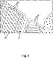
- Fig. 2:
- erkannte Streckenabschnitte,
- Fig. 3:
- zusammengefasst Gebiete,
- Fig. 4:
- Feldgrenzen mit Lücken aus Messfehlern und
- Fig. 5:
- Feldgrenzen ohne Lücken.
- In
Figur 1 sind eine Vielzahl von Positionsfixen 1 einer Arbeitsmaschine gezeigt. Vor der eigentlichen Analyse werden die Positionsfixe 1 mit einer Karte verglichen und die Positionsfixe 1, die im Wesentlichen auf einer Straße 2 liegen, werden bei der Analyse nicht berücksichtigt. Die anderen Positionsfixe 1 werden auf gerade Streckenabschnitte 3 hin analysiert. Als im Wesentlichen Gerade wird ein Streckenabschnitt angesehen, wenn eine Folge von Positionsfixen 1 keinen Winkel oberhalb eines Maximalwinkels aufweist. - In
Figur 2 sind erkannte gerade Streckenabschnitte 3, 4, 5 gezeigt. Die Streckenabschnitte 3, 4, 5 werden danach auf Parallelität überprüft. Dann wird für parallele Streckenabschnitte 3, 4, 5 der Normalabstand 9 bestimmt. Der Normalabstand ist die Länge einer Strecke von einem Streckenabschnitt zum anderen, die im Wesentlichen senkrecht zu den parallelen Streckenabschnitten verläuft. Ist der Normalabstand kleiner als ein Grenzwert, so werden die parallelen Streckenabschnitte 3, 4, 5 zu einem Gebiet 6, 7, 8 zusammengefasst. Die entstehenden Gebiete sind inFigur 3 dargestellt. Die Gebiete 6, 7, 8 können sowohl Innenfeld 6 als auch Vorgewende 7, 8 darstellen. Was ein Gebiet darstellt kann sich bspw. aus der Lage, Form und/oder Größe der Gebiete ergeben. Alternativ kann die Unterteilung in Vorgewende und Innenfeld auch anhand weiterer mit dem Positionsfix 1 verknüpfte Daten erfolgen, wenn solche Daten vorliegen. - Im nächsten Schritt werden Gebiete 6, 7, 8, die wahrscheinlich im selben Feld liegen zusammengefasst. Dazu werden die geraden Streckenabschnitte eines Gebietes 6 in gerader Linie verlängert. Der Wert der Verlängerung hängt dabei bevorzugt von dem Abstand zwischen den Positionsfixen 1 ab. Der Abstand zwischen den Positionsfixen 1 hängt wiederum von der Fahrgeschwindigkeit der Arbeitsmaschine während der Aufnahme der Positionsfixe 1 und dem Aufnahmeintervall, also dem zeitlichen Abstand zwischen den Positionsfixen 1 ab. Überlappt eine Verlängerung mit einem anderen Gebiet 7, so liegt dieses Gebiet wahrscheinlich im gleichen Feld wie der verlängerte Streckenabschnitt 6. Bevorzugt werden Streckenabschnitte 3 verlängert, die in einem Innenfeld 6 liegen. Verlängerungen von Streckenabschnitten eines Innenfeldes 6 überlappen häufig mit Gebieten, die Vorgewende 7 darstellen. Das Gebiet 7 in dem der verlängerte Streckenabschnitt liegt und das Gebiet zu dem der Streckenabschnitt 6 gehören zu einem Feld. Die Gebiete 6, 7 werden dann zu einem Feld zusammengefasst.
- Zu den so bestimmten Feldern 10, 11 werden dann die Feldgrenzen 12, 13 ermittelt. Zu den Feldern wird der Mittelwert der Normalabstände 9 bestimmten. Dieser entspricht der Arbeitsbreite. Die Feldgrenze 12, 13 befindet sich eine halbe Arbeitsbreite außerhalb des äußersten Streckenabschnitts. In
Figur 4 sind zwei Felder 10, 11 mit Feldgrenzen 12, 13 gezeigt. Feldgrenzen 12 im Inneren von Feldern 11 können dabei durch Bereiche entstehen, in denen die Arbeitsmaschine nicht war, durch Bereiche in denen kein Positionsfix 1 ermittelt werden konnte oder durch Messfehler bei der Bestimmung der Positionsfixe 1. Im ersten Fall ist die innere Feldgrenze 12 korrekt ermittelt worden. Fälle in denen keine Bestimmung eines Positionsfix 1 möglich war, lassen sich an einem ungewöhnlich großen Abstand zwischen Positionsfixen erkennen und die Lücke kann zum Feld 11 gezählt werden. - Zur Beseitigung von Lücken, die durch Messfehler bei der Bestimmung der Positionsfixe 1 entstanden sind, werden die Feldgrenzen 12, 13 vergrößert. Durch die Vergrößerung werden Lücken geschlossen und innere Feldgrenzen 12 verschwinden. Anschließend werden die Feldgrenzen 12, 13 um den gleichen Wert verkleinert. In
Figur 5 sind zwei Felder 10, 11 mit geschlossenen Lücken dargestellt. Äußere Feldgrenzen 13 und korrekte innere Feldgrenzen 12 bleiben durch dieses Verfahren unverändert. -
- 1
- Positionsfixe
- 2
- Straße
- 3
- gerade Streckenabschnitte
- 4
- gerade Streckenabschnitte
- 5
- gerade Streckenabschnitte
- 6
- Gebiet, Innenfeld
- 7
- Gebiet, Vorgewende
- 8
- Gebiet, Vorgewende
- 9
- Normalabstand
- 10
- Feld
- 11
- Feld
- 12
- Innere Feldgrenze
- 13
- Äußere Feldgrenze
Claims (12)
- Verfahren zum Erkennen von Feldgrenzen, umfassend die Schritte:a) Analysieren einer Vielzahl von Positionsfixen (1) einer Arbeitsmaschine und zugehörigen Zeitstempeln auf im Wesentlichen gerade Streckenabschnitte (3, 4, 5),b) Zusammenfassen von parallelen Streckenabschnitten (3, 4, 5) zu Gebieten (6, 7,8),c) Verlängern der geraden Streckenabschnitte (3, 4, 5),d) prüfen ob ein verlängerter Streckenabschnitt (3, 4, 5) in einem anderen Gebiet (6, 7, 8) liegt,e) Zusammenfassen des Gebietes (6, 7, 8) in dem der verlängerte Streckenabschnitt liegt mit dem Gebiet (6, 7, 8) zu dem der Streckenabschnitt (3, 4, 5) gehört zu einem Feld (10, 11),f) Bestimmen einer geschlossenen Feldgrenze (12, 13) um das Feld.
- Verfahren nach Anspruch 1, wobei die Positionsfixe (1) von einer einzigen Arbeitsmaschine aufgenommen wurden.
- Verfahren nach Anspruch 1, wobei den Positionsfixen (1) ein Identifikationsmerkmal der Arbeitsmaschine zugeordnet ist.
- Verfahren nach einem der vorhergehenden Ansprüche, wobei drei zeitlich aufeinander folgende Positionsfixe (1) zu einem geraden Streckenabschnitt (3, 4, 5) gehören, wenn die zwei Vektoren zwischen jeweils zwei zeitlich aufeinander folgende Positionsfixe (1) einen Winkel unterhalb eines vorbestimmten Maximalwinkels einschließen.
- Verfahren nach einem der vorhergehenden Ansprüche, wobei in Schritt b) nur parallele Streckenabschnitte (3, 4, 5) zu Gebieten (6, 7, 8) zusammengefasst werden, deren Normalabstand (9) einen Grenzwert nicht überschreitet.
- Verfahren nach einem der vorhergehenden Ansprüche, wobei die Gebiete (6, 7, 8) in Innenfeld und Vorgewende eingeteilt werden.
- Verfahren nach einem der vorhergehenden Ansprüche, wobei in Schritt c) die Streckenabschnitte (3, 4, 5) um einen Wert verlängert werden, der von dem Abstand zwischen zwei Positionsfixen (1) auf dem Streckenabschnitt (3, 4, 5) abhängt.
- Verfahren nach einem der vorhergehenden Ansprüche, wobei aus dem Normalabstand (9) der parallelen Streckenabschnitte (3, 4, 5) die Arbeitsbreite bestimmt wird und die Feldgrenze (12, 13) um eine halbe Arbeitsbreite vergrößert wird.
- Verfahren nach einem der vorhergehenden Ansprüche, wobei die Feldgrenzen (12, 13) um einen vorbestimmten Wert vergrößert werden und anschließend um den gleichen Wert verkleinert werden.
- Verfahren nach einem der vorhergehenden Ansprüche, wobei die Positionsfixe (1) vor Schritt a) mit einer Karte verglichen werden und Positionsfixe (1), die im Wesentlichen auf einer Straße (2) liegen, in den Verfahrensschritten unberücksichtigt bleiben.
- Verfahren nach einem der vorhergehenden Ansprüche, wobei zu jedem Positionsfix (1) weitere mit dem Positionsfix (1) verknüpfte Daten vorliegen, wobei aus den verknüpften Daten bestimmt wird ob an dem Positionsfix (1) eine Feldarbeit verrichtet wurde und in den Verfahrensschritten nur Positionsfixe (1) verarbeitet werden, an denen Feldarbeit verrichtet wurde.
- Verfahren nach Anspruch 11, wobei die verknüpften Daten den Leistungsbedarf der Arbeitsmaschine, Einstellungen von Arbeitsaggregaten der Arbeitsmaschine und/oder Messwerte von Sensoren der Arbeitsmaschine umfassen.
Applications Claiming Priority (1)
| Application Number | Priority Date | Filing Date | Title |
|---|---|---|---|
| DE102020105980.9A DE102020105980A1 (de) | 2020-03-05 | 2020-03-05 | Verfahren zum Erkennen von Feldgrenzen |
Publications (2)
| Publication Number | Publication Date |
|---|---|
| EP3874927A1 true EP3874927A1 (de) | 2021-09-08 |
| EP3874927B1 EP3874927B1 (de) | 2022-11-30 |
Family
ID=73740309
Family Applications (1)
| Application Number | Title | Priority Date | Filing Date |
|---|---|---|---|
| EP20212247.9A Active EP3874927B1 (de) | 2020-03-05 | 2020-12-07 | Verfahren zum erkennen von feldgrenzen |
Country Status (2)
| Country | Link |
|---|---|
| EP (1) | EP3874927B1 (de) |
| DE (1) | DE102020105980A1 (de) |
Citations (6)
| Publication number | Priority date | Publication date | Assignee | Title |
|---|---|---|---|---|
| EP2257889A1 (de) * | 2008-03-20 | 2010-12-08 | Deere & Company | System und verfahren zur erzeugung einer inneren grenze eines arbeitsbereichs |
| US20110160994A1 (en) * | 2009-12-29 | 2011-06-30 | Agco Corporation | Auto-detection of a field in fleet management |
| US20150302305A1 (en) * | 2014-04-21 | 2015-10-22 | The Climate Corporation | Generating an agriculture prescription |
| US9933787B2 (en) * | 2013-04-29 | 2018-04-03 | 101227980 Saskatchewan Ltd. | Method and system for determining optimized travel path for agricultural implement on land with obstacle |
| CN109310042A (zh) * | 2016-09-05 | 2019-02-05 | 株式会社久保田 | 作业车自动行驶系统、行驶路径管理装置、行驶路径生成装置、行驶路径决定装置 |
| EP3449286B1 (de) | 2016-04-27 | 2019-12-11 | Farmdok GmbH | Verfahren zum detektieren landwirtschaftlicher, von einem fahrzeug ausgeführter feldarbeit |
-
2020
- 2020-03-05 DE DE102020105980.9A patent/DE102020105980A1/de not_active Withdrawn
- 2020-12-07 EP EP20212247.9A patent/EP3874927B1/de active Active
Patent Citations (6)
| Publication number | Priority date | Publication date | Assignee | Title |
|---|---|---|---|---|
| EP2257889A1 (de) * | 2008-03-20 | 2010-12-08 | Deere & Company | System und verfahren zur erzeugung einer inneren grenze eines arbeitsbereichs |
| US20110160994A1 (en) * | 2009-12-29 | 2011-06-30 | Agco Corporation | Auto-detection of a field in fleet management |
| US9933787B2 (en) * | 2013-04-29 | 2018-04-03 | 101227980 Saskatchewan Ltd. | Method and system for determining optimized travel path for agricultural implement on land with obstacle |
| US20150302305A1 (en) * | 2014-04-21 | 2015-10-22 | The Climate Corporation | Generating an agriculture prescription |
| EP3449286B1 (de) | 2016-04-27 | 2019-12-11 | Farmdok GmbH | Verfahren zum detektieren landwirtschaftlicher, von einem fahrzeug ausgeführter feldarbeit |
| CN109310042A (zh) * | 2016-09-05 | 2019-02-05 | 株式会社久保田 | 作业车自动行驶系统、行驶路径管理装置、行驶路径生成装置、行驶路径决定装置 |
Also Published As
| Publication number | Publication date |
|---|---|
| DE102020105980A1 (de) | 2021-09-09 |
| EP3874927B1 (de) | 2022-11-30 |
Similar Documents
| Publication | Publication Date | Title |
|---|---|---|
| DE60200382T2 (de) | Darstellung der Krümmung geographischer Merkmale mit Hilfe von Biegekoeffizienten | |
| EP0789341B1 (de) | Fahrzeugautonome Detektion von Verkehrsstau | |
| EP2020589A2 (de) | Verfahren zur Anzeige einer Manöverschemaansicht in einem Navigationssystem | |
| EP2511892B1 (de) | Verfahren zum Detektieren eines Grenzübertritts | |
| DE102018221054B4 (de) | Verfahren zum Bereitstellen von Kartendaten in einem Kraftfahrzeug, Kraftfahrzeug und zentrale Datenverarbeitungseinrichtung | |
| EP3239903B1 (de) | Verfahren und vorrichtung zum vergleichen zweier karten mit darin hinterlegten landmarken | |
| DE102009043764A1 (de) | Navigationsvorrichtung und Navigationsverfahren für ein Fahrzeug | |
| EP2078927A2 (de) | Verfahren zum Betrieb eines Navigationssystems mit graphischer Darstellung von Fahrspuranweisungen | |
| DE10138641A1 (de) | Verfahren zur Bestimmung einer Modellfahrbahn | |
| WO1995014910A1 (de) | Verfahren zur erzeugung einer digitalisierten strassennetzkarte | |
| DE3429882C2 (de) | ||
| EP3161808B1 (de) | Verfahren zum verarbeiten von messdaten eines fahrzeuges zur bestimmung des beginns einer parkplatzsuche und computerprogrammprodukt | |
| DE102018122374A1 (de) | Verfahren zum Bestimmen eines ein Kraftfahrzeug umgebenden Freiraums, Computerprogrammprodukt, Freiraumbestimmungseinrichtung und Kraftfahrzeug | |
| DE102014212866A1 (de) | Verfahren zum Ermitteln eines Parkplatzes aus einer Anzahl von Messpunkten | |
| EP2431712B1 (de) | Verfahren zum Ermitteln der Länge des von einem Fahrzeug zurückgelegten Wegs | |
| DE102016013972A1 (de) | Fahrerassistenzsystem und -verfahren | |
| DE102014216383A1 (de) | Verfahren und Vorrichtung zur Bereitstellung der Fahrzeugnavigationsinformation im Bereich einer Hochstraße | |
| EP3991144A1 (de) | Verfahren, computerprogramm und vorrichtung zur verarbeitung von durch ein kraftfahrzeug erfassten daten | |
| EP4108545A1 (de) | Verfahren zum bestimmen einer aktuell befahrbaren trajektorie für ein zumindest teilweise assistiert betriebenes kraftfahrzeug, sowie assistenzsystem | |
| DE102014210752A1 (de) | Verfahren und Vorrichtung zum Überwachen einer Solltrajektorie eines Fahrzeugs | |
| DE102004003502B3 (de) | Verfahren und Vorrichtung zum Assistieren beim Führen eines Kraftfahrzeugs | |
| EP3279051B1 (de) | Steuerungs-system und steuerungs-verfahren zur auswahl und verfolgung eines kraftfahrzeugs | |
| DE102013217060B4 (de) | Spurgenaue Positionierung eines Fahrzeugs | |
| DE102018218043A1 (de) | Ermittlung einer Anzahl von Fahrspuren sowie von Spurmarkierungen auf Straßenabschnitten | |
| EP0905482B1 (de) | Verfahren zur computergestützten Kartierung |
Legal Events
| Date | Code | Title | Description |
|---|---|---|---|
| PUAI | Public reference made under article 153(3) epc to a published international application that has entered the european phase |
Free format text: ORIGINAL CODE: 0009012 |
|
| STAA | Information on the status of an ep patent application or granted ep patent |
Free format text: STATUS: THE APPLICATION HAS BEEN PUBLISHED |
|
| AK | Designated contracting states |
Kind code of ref document: A1 Designated state(s): AL AT BE BG CH CY CZ DE DK EE ES FI FR GB GR HR HU IE IS IT LI LT LU LV MC MK MT NL NO PL PT RO RS SE SI SK SM TR |
|
| STAA | Information on the status of an ep patent application or granted ep patent |
Free format text: STATUS: REQUEST FOR EXAMINATION WAS MADE |
|
| 17P | Request for examination filed |
Effective date: 20220309 |
|
| RBV | Designated contracting states (corrected) |
Designated state(s): AL AT BE BG CH CY CZ DE DK EE ES FI FR GB GR HR HU IE IS IT LI LT LU LV MC MK MT NL NO PL PT RO RS SE SI SK SM TR |
|
| GRAP | Despatch of communication of intention to grant a patent |
Free format text: ORIGINAL CODE: EPIDOSNIGR1 |
|
| STAA | Information on the status of an ep patent application or granted ep patent |
Free format text: STATUS: GRANT OF PATENT IS INTENDED |
|
| INTG | Intention to grant announced |
Effective date: 20220719 |
|
| GRAS | Grant fee paid |
Free format text: ORIGINAL CODE: EPIDOSNIGR3 |
|
| GRAA | (expected) grant |
Free format text: ORIGINAL CODE: 0009210 |
|
| STAA | Information on the status of an ep patent application or granted ep patent |
Free format text: STATUS: THE PATENT HAS BEEN GRANTED |
|
| AK | Designated contracting states |
Kind code of ref document: B1 Designated state(s): AL AT BE BG CH CY CZ DE DK EE ES FI FR GB GR HR HU IE IS IT LI LT LU LV MC MK MT NL NO PL PT RO RS SE SI SK SM TR |
|
| REG | Reference to a national code |
Ref country code: CH Ref legal event code: EP Ref country code: GB Ref legal event code: FG4D Free format text: NOT ENGLISH |
|
| REG | Reference to a national code |
Ref country code: AT Ref legal event code: REF Ref document number: 1533934 Country of ref document: AT Kind code of ref document: T Effective date: 20221215 Ref country code: DE Ref legal event code: R096 Ref document number: 502020002103 Country of ref document: DE |
|
| REG | Reference to a national code |
Ref country code: IE Ref legal event code: FG4D Free format text: LANGUAGE OF EP DOCUMENT: GERMAN |
|
| REG | Reference to a national code |
Ref country code: LT Ref legal event code: MG9D |
|
| REG | Reference to a national code |
Ref country code: NL Ref legal event code: MP Effective date: 20221130 |
|
| PG25 | Lapsed in a contracting state [announced via postgrant information from national office to epo] |
Ref country code: SE Free format text: LAPSE BECAUSE OF FAILURE TO SUBMIT A TRANSLATION OF THE DESCRIPTION OR TO PAY THE FEE WITHIN THE PRESCRIBED TIME-LIMIT Effective date: 20221130 Ref country code: PT Free format text: LAPSE BECAUSE OF FAILURE TO SUBMIT A TRANSLATION OF THE DESCRIPTION OR TO PAY THE FEE WITHIN THE PRESCRIBED TIME-LIMIT Effective date: 20230331 Ref country code: NO Free format text: LAPSE BECAUSE OF FAILURE TO SUBMIT A TRANSLATION OF THE DESCRIPTION OR TO PAY THE FEE WITHIN THE PRESCRIBED TIME-LIMIT Effective date: 20230228 Ref country code: LT Free format text: LAPSE BECAUSE OF FAILURE TO SUBMIT A TRANSLATION OF THE DESCRIPTION OR TO PAY THE FEE WITHIN THE PRESCRIBED TIME-LIMIT Effective date: 20221130 Ref country code: FI Free format text: LAPSE BECAUSE OF FAILURE TO SUBMIT A TRANSLATION OF THE DESCRIPTION OR TO PAY THE FEE WITHIN THE PRESCRIBED TIME-LIMIT Effective date: 20221130 Ref country code: ES Free format text: LAPSE BECAUSE OF FAILURE TO SUBMIT A TRANSLATION OF THE DESCRIPTION OR TO PAY THE FEE WITHIN THE PRESCRIBED TIME-LIMIT Effective date: 20221130 |
|
| PG25 | Lapsed in a contracting state [announced via postgrant information from national office to epo] |
Ref country code: RS Free format text: LAPSE BECAUSE OF FAILURE TO SUBMIT A TRANSLATION OF THE DESCRIPTION OR TO PAY THE FEE WITHIN THE PRESCRIBED TIME-LIMIT Effective date: 20221130 Ref country code: PL Free format text: LAPSE BECAUSE OF FAILURE TO SUBMIT A TRANSLATION OF THE DESCRIPTION OR TO PAY THE FEE WITHIN THE PRESCRIBED TIME-LIMIT Effective date: 20221130 Ref country code: LV Free format text: LAPSE BECAUSE OF FAILURE TO SUBMIT A TRANSLATION OF THE DESCRIPTION OR TO PAY THE FEE WITHIN THE PRESCRIBED TIME-LIMIT Effective date: 20221130 Ref country code: IS Free format text: LAPSE BECAUSE OF FAILURE TO SUBMIT A TRANSLATION OF THE DESCRIPTION OR TO PAY THE FEE WITHIN THE PRESCRIBED TIME-LIMIT Effective date: 20230330 Ref country code: HR Free format text: LAPSE BECAUSE OF FAILURE TO SUBMIT A TRANSLATION OF THE DESCRIPTION OR TO PAY THE FEE WITHIN THE PRESCRIBED TIME-LIMIT Effective date: 20221130 Ref country code: GR Free format text: LAPSE BECAUSE OF FAILURE TO SUBMIT A TRANSLATION OF THE DESCRIPTION OR TO PAY THE FEE WITHIN THE PRESCRIBED TIME-LIMIT Effective date: 20230301 |
|
| P01 | Opt-out of the competence of the unified patent court (upc) registered |
Effective date: 20230516 |
|
| PG25 | Lapsed in a contracting state [announced via postgrant information from national office to epo] |
Ref country code: NL Free format text: LAPSE BECAUSE OF FAILURE TO SUBMIT A TRANSLATION OF THE DESCRIPTION OR TO PAY THE FEE WITHIN THE PRESCRIBED TIME-LIMIT Effective date: 20221130 |
|
| PG25 | Lapsed in a contracting state [announced via postgrant information from national office to epo] |
Ref country code: SM Free format text: LAPSE BECAUSE OF FAILURE TO SUBMIT A TRANSLATION OF THE DESCRIPTION OR TO PAY THE FEE WITHIN THE PRESCRIBED TIME-LIMIT Effective date: 20221130 Ref country code: RO Free format text: LAPSE BECAUSE OF FAILURE TO SUBMIT A TRANSLATION OF THE DESCRIPTION OR TO PAY THE FEE WITHIN THE PRESCRIBED TIME-LIMIT Effective date: 20221130 Ref country code: EE Free format text: LAPSE BECAUSE OF FAILURE TO SUBMIT A TRANSLATION OF THE DESCRIPTION OR TO PAY THE FEE WITHIN THE PRESCRIBED TIME-LIMIT Effective date: 20221130 Ref country code: DK Free format text: LAPSE BECAUSE OF FAILURE TO SUBMIT A TRANSLATION OF THE DESCRIPTION OR TO PAY THE FEE WITHIN THE PRESCRIBED TIME-LIMIT Effective date: 20221130 Ref country code: CZ Free format text: LAPSE BECAUSE OF FAILURE TO SUBMIT A TRANSLATION OF THE DESCRIPTION OR TO PAY THE FEE WITHIN THE PRESCRIBED TIME-LIMIT Effective date: 20221130 |
|
| REG | Reference to a national code |
Ref country code: BE Ref legal event code: MM Effective date: 20221231 |
|
| PG25 | Lapsed in a contracting state [announced via postgrant information from national office to epo] |
Ref country code: SK Free format text: LAPSE BECAUSE OF FAILURE TO SUBMIT A TRANSLATION OF THE DESCRIPTION OR TO PAY THE FEE WITHIN THE PRESCRIBED TIME-LIMIT Effective date: 20221130 Ref country code: LU Free format text: LAPSE BECAUSE OF NON-PAYMENT OF DUE FEES Effective date: 20221207 Ref country code: AL Free format text: LAPSE BECAUSE OF FAILURE TO SUBMIT A TRANSLATION OF THE DESCRIPTION OR TO PAY THE FEE WITHIN THE PRESCRIBED TIME-LIMIT Effective date: 20221130 |
|
| REG | Reference to a national code |
Ref country code: DE Ref legal event code: R097 Ref document number: 502020002103 Country of ref document: DE |
|
| PLBE | No opposition filed within time limit |
Free format text: ORIGINAL CODE: 0009261 |
|
| STAA | Information on the status of an ep patent application or granted ep patent |
Free format text: STATUS: NO OPPOSITION FILED WITHIN TIME LIMIT |
|
| PG25 | Lapsed in a contracting state [announced via postgrant information from national office to epo] |
Ref country code: IE Free format text: LAPSE BECAUSE OF NON-PAYMENT OF DUE FEES Effective date: 20221207 |
|
| 26N | No opposition filed |
Effective date: 20230831 |
|
| PG25 | Lapsed in a contracting state [announced via postgrant information from national office to epo] |
Ref country code: SI Free format text: LAPSE BECAUSE OF FAILURE TO SUBMIT A TRANSLATION OF THE DESCRIPTION OR TO PAY THE FEE WITHIN THE PRESCRIBED TIME-LIMIT Effective date: 20221130 Ref country code: BE Free format text: LAPSE BECAUSE OF NON-PAYMENT OF DUE FEES Effective date: 20221231 |
|
| PG25 | Lapsed in a contracting state [announced via postgrant information from national office to epo] |
Ref country code: CY Free format text: LAPSE BECAUSE OF FAILURE TO SUBMIT A TRANSLATION OF THE DESCRIPTION OR TO PAY THE FEE WITHIN THE PRESCRIBED TIME-LIMIT Effective date: 20221130 |
|
| PG25 | Lapsed in a contracting state [announced via postgrant information from national office to epo] |
Ref country code: MK Free format text: LAPSE BECAUSE OF FAILURE TO SUBMIT A TRANSLATION OF THE DESCRIPTION OR TO PAY THE FEE WITHIN THE PRESCRIBED TIME-LIMIT Effective date: 20221130 Ref country code: IT Free format text: LAPSE BECAUSE OF FAILURE TO SUBMIT A TRANSLATION OF THE DESCRIPTION OR TO PAY THE FEE WITHIN THE PRESCRIBED TIME-LIMIT Effective date: 20221130 |
|
| PG25 | Lapsed in a contracting state [announced via postgrant information from national office to epo] |
Ref country code: MC Free format text: LAPSE BECAUSE OF FAILURE TO SUBMIT A TRANSLATION OF THE DESCRIPTION OR TO PAY THE FEE WITHIN THE PRESCRIBED TIME-LIMIT Effective date: 20221130 |
|
| PG25 | Lapsed in a contracting state [announced via postgrant information from national office to epo] |
Ref country code: MC Free format text: LAPSE BECAUSE OF FAILURE TO SUBMIT A TRANSLATION OF THE DESCRIPTION OR TO PAY THE FEE WITHIN THE PRESCRIBED TIME-LIMIT Effective date: 20221130 |
|
| PG25 | Lapsed in a contracting state [announced via postgrant information from national office to epo] |
Ref country code: BG Free format text: LAPSE BECAUSE OF FAILURE TO SUBMIT A TRANSLATION OF THE DESCRIPTION OR TO PAY THE FEE WITHIN THE PRESCRIBED TIME-LIMIT Effective date: 20221130 |
|
| REG | Reference to a national code |
Ref country code: CH Ref legal event code: PL |
|
| PG25 | Lapsed in a contracting state [announced via postgrant information from national office to epo] |
Ref country code: MT Free format text: LAPSE BECAUSE OF FAILURE TO SUBMIT A TRANSLATION OF THE DESCRIPTION OR TO PAY THE FEE WITHIN THE PRESCRIBED TIME-LIMIT Effective date: 20221130 |
|
| PG25 | Lapsed in a contracting state [announced via postgrant information from national office to epo] |
Ref country code: CH Free format text: LAPSE BECAUSE OF NON-PAYMENT OF DUE FEES Effective date: 20231231 |
|
| PG25 | Lapsed in a contracting state [announced via postgrant information from national office to epo] |
Ref country code: CH Free format text: LAPSE BECAUSE OF NON-PAYMENT OF DUE FEES Effective date: 20231231 |
|
| PG25 | Lapsed in a contracting state [announced via postgrant information from national office to epo] |
Ref country code: HU Free format text: LAPSE BECAUSE OF FAILURE TO SUBMIT A TRANSLATION OF THE DESCRIPTION OR TO PAY THE FEE WITHIN THE PRESCRIBED TIME-LIMIT; INVALID AB INITIO Effective date: 20201207 |
|
| GBPC | Gb: european patent ceased through non-payment of renewal fee |
Effective date: 20241207 |
|
| PG25 | Lapsed in a contracting state [announced via postgrant information from national office to epo] |
Ref country code: GB Free format text: LAPSE BECAUSE OF NON-PAYMENT OF DUE FEES Effective date: 20241207 |
|
| PG25 | Lapsed in a contracting state [announced via postgrant information from national office to epo] |
Ref country code: TR Free format text: LAPSE BECAUSE OF FAILURE TO SUBMIT A TRANSLATION OF THE DESCRIPTION OR TO PAY THE FEE WITHIN THE PRESCRIBED TIME-LIMIT Effective date: 20221130 |
|
| PGFP | Annual fee paid to national office [announced via postgrant information from national office to epo] |
Ref country code: DE Payment date: 20251211 Year of fee payment: 6 |
|
| PGFP | Annual fee paid to national office [announced via postgrant information from national office to epo] |
Ref country code: AT Payment date: 20260113 Year of fee payment: 5 |
|
| PGFP | Annual fee paid to national office [announced via postgrant information from national office to epo] |
Ref country code: FR Payment date: 20251229 Year of fee payment: 6 |
|
| PG25 | Lapsed in a contracting state [announced via postgrant information from national office to epo] |
Ref country code: CH Free format text: THE PATENT HAS BEEN ANNULLED BY A DECISION OF A NATIONAL AUTHORITY Effective date: 20231231 |