EP3874570B1 - Vorrichtung zur manipulation der bewegung einer freileitung - Google Patents
Vorrichtung zur manipulation der bewegung einer freileitung Download PDFInfo
- Publication number
- EP3874570B1 EP3874570B1 EP19786955.5A EP19786955A EP3874570B1 EP 3874570 B1 EP3874570 B1 EP 3874570B1 EP 19786955 A EP19786955 A EP 19786955A EP 3874570 B1 EP3874570 B1 EP 3874570B1
- Authority
- EP
- European Patent Office
- Prior art keywords
- power line
- signal
- overhead power
- acceleration
- controller
- Prior art date
- Legal status (The legal status is an assumption and is not a legal conclusion. Google has not performed a legal analysis and makes no representation as to the accuracy of the status listed.)
- Active
Links
Images


Classifications
-
- H—ELECTRICITY
- H02—GENERATION; CONVERSION OR DISTRIBUTION OF ELECTRIC POWER
- H02G—INSTALLATION OF ELECTRIC CABLES OR LINES, OR OF COMBINED OPTICAL AND ELECTRIC CABLES OR LINES
- H02G7/00—Overhead installations of electric lines or cables
- H02G7/16—Devices for removing snow or ice from lines or cables
-
- H—ELECTRICITY
- H02—GENERATION; CONVERSION OR DISTRIBUTION OF ELECTRIC POWER
- H02G—INSTALLATION OF ELECTRIC CABLES OR LINES, OR OF COMBINED OPTICAL AND ELECTRIC CABLES OR LINES
- H02G7/00—Overhead installations of electric lines or cables
- H02G7/14—Arrangements or devices for damping mechanical oscillations of lines, e.g. for reducing production of sound
Definitions
- the invention relates to a device to be attached to an overhead power line for the purpose of manipulating movement of the overhead power line.
- Overhead power line arrangements are structures widely used in transmitting and distributing electric power, typically along large distances.
- a power line arrangement includes a number of power lines or conductors, usually three or multiples of three, which are suspended by towers, pylons or poles arranged at intervals along the power lines.
- Power lines are exposed to various external forces and environmental influence, such as meteorological phenomena.
- Power lines are also exposed to icing, which is particularly noticeable in polar geographical areas. Formation of ice on the power lines may cause heavy loads on the conductors and may likewise lead to damage and costly disruption in service.
- CN-104065015 describes an external excitation resonance type automatic anti-icing and de-icing robot system.
- the system includes a vibration execution module, an online electricity taking module, an automatic monitoring module, a control analysis module, a resonance feedback module, a fixing locking module and a wireless remote control module.
- the vibration execution module is controlled by the control analysis module to generate mechanical vibration with the same frequency as the inherent frequency of a current electricity transmission line.
- the resonance feedback module measures the resonance situation in real time, the vibration frequency of the vibration execution module is continuously tracked and adjusted through the control analysis module, and the de-icing efficiency and effect are kept.
- WO-02/47232 A1 relates to an operatively controllable electromechanical vibrator which is attached semi-permanently on a line section between pylons in order to remove snow and ice from an overhead line.
- a snow/ice sensor is arranged close by the vibrator, and the vibrator is driven from a current transformer mounted close by for inductive tapping of power from the power line.
- CN104065015 describes an external excitation resonance type automatic anti-icing and de-icing robot system which is composed of a vibration execution module, an online electricity taking module, an automatic monitoring module, a control analysis module, a resonance feedback module, a fixing locking module and a wireless remote control module.
- the vibration execution module is controlled by the control analysis module to generate mechanical vibration with the frequency the same as the inherent frequency of a current electricity transmission line so as to achieve the online anti-icing and de-icing functions.
- the resonance feedback module measures the resonance situation in real time, the vibration frequency of the vibration execution module is continuously tracked and adjusted through the control analysis module, and the de-icing efficiency and effect are kept.
- the external excitation resonance type automatic anti-icing and de-icing robot system automatically begins to work in the initial icing forming stage, damage caused by serious icing to the line is effectively prevented, the external excitation type automatic anti-icing and de-icing robot system is simple and compact in structure, small in size, low in cost, unmovable and low in energy consumption, the defects of other de-icing modes are avoided, and the full-automatic, intelligent and efficient electricity transmission line anti-icing and de-icing work can be achieved.
- US2014136140 describes a system for monitoring motion of an overhead line and which includes a monitoring device.
- the monitoring device includes an accelerometer and a processing circuit.
- the processing circuit is configured to accept data from the accelerometer corresponding to line movement, analyze the data to determine displacement data corresponding to a displacement of the overhead line, accept data corresponding to a location of at least one external object proximate to the overhead line, and analyze the displacement data to determine a clearance from the at least one external object.
- CN-105244831 discloses a smart shockproof hammer for reducing vibration or galloping of overhead power lines. Data collected by a triaxial acceleration sensor are processed in a processor, which controls a motor to perform the active reverse movement of the hammer to achieve the shock protection effect.
- US-6 660 934 B1 relates to a mechanical ice-shedding device for temporary or permanent attachment to a suspended power line.
- the ice-shedding device uses a motor to move at least one unbalanced weight, thereby causing a vibration of the device that is translated to the cable to which the device is attached.
- the vibration causes an oscillation of the cable which is sufficient to substantially shed ice that has accumulated thereon.
- the output of the motor is preferably regulated so that the cable may be ramped through several frequencies of oscillation, thereby improving its ice-shedding ability.
- the device may be driven by power from the power line to which it is attached, or from another source, such as a battery or storage capacitor.
- the present invention relates to a device to be attached to an overhead power line for the purpose of manipulating movement of the overhead power line, the device comprising:
- the controller device may be configured to be in different modes, dependent on signals from the sensing devices, a timer etc.
- the controller device In a first period of time, for example determined by the timer or signals from the sensing devices, the controller device is configured to be in the overhead power line stabilizing mode. This will be the case most of the time.
- the controller device in a second period of time, different from the first period of time, the controller device may be configured to be in the ice removal mode.
- the controller device can have several different modes - but the controller device is not in different modes at the same time.
- the device comprises one flywheel, one electric motor and one actuator.
- the device comprises two flywheels, two respective electric motors and two respective actuators.
- the device comprises an external housing, the clamp being arranged on an upper part of the external housing.
- the clamp includes a locking device configured to lock the device to the overhead power line, the locking device including a locking actuator which is controllable by the controller device.
- the acceleration sensing device includes a 3-axis accelerometer or a 3-axis gyroscope.
- the electric power source includes an inductive coupler, arranged to provide electric power from AC carried by the overhead power line, and a power converter.
- the electric power source further comprises a rechargeable battery device.
- the device comprises a communication device connected to the controller device, providing wireless communication with a base station.
- the device comprises a temperature sensor device in the clamp, arranged to measure a temperature of the overhead power cable, and wherein the controller device is arranged to receive a temperature signal from the temperature sensor device.
- the device comprises an ice formation detector, and wherein the controller device is arranged to receive an ice formation detector signal from the ice formation detector.
- the device comprises a distance measurement device, measuring a vertical distance between the device and the ground, and wherein the controller device is arranged to receive a distance measurement signal from the distance measurement device.
- the present invention is directed to a device to be attached to an overhead power line for the purpose of manipulating movement of the overhead power line.
- the following description presents exemplary embodiments of such devices and various aspects thereof that are consistent with the principles of the invention. It must be noted that the exemplary embodiments are intended to provide a better understanding of the invention, and that they should not be interpreted as limitations to the invention. The scope of the invention is defined by the appended claims.
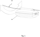
- Figure 1 illustrates a device 100 to be attached to an overhead power line 200 for the purpose of manipulating movement of the overhead power line 200.
- an overhead power line arrangement includes of a number of power lines or conductors, usually three or multiples of three, which are suspended by towers, pylons or poles arranged at intervals along the power lines.
- the device 100 during use is arranged on a portion of the power line 200 between two towers, pylons or poles.
- the device 100 will be arranged halfway or substantially halfway between two adjacent towers, pylons or poles.
- one device 100 will typically be arranged on each of the power lines.
- Figure 2 is a schematic exploded perspective view that illustrates principles of a first embodiment of the device 100.
- the device 100 comprises an electric power source 110; a base 120, which defines a base plane.
- the base and the internal components is surrounded by an external housing, which may include a lower housing portion 102 and a top housing portion 104, which are secured along an upper rim on the lower housing portion 102 and a lower rim on the upper housing portion 104 to form a watertight and rugged housing.
- the housing portions 102, 104 may, e.g., be made of a thermoplastic polymer material such as polycarbonate, in particular an UV stable polycarbonate.
- the housing portions 102, 104 may advantageously be formed with a smooth and slippery outer surface, in order to avoid fastening of snow and/or ice during use in frosty and humid conditions.
- a clamp 130 is secured relatively to the base, usually indirectly via the housing.
- the clamp 130 is mounted on the upper part of the top housing portion 104, which is again attached to the lower housing portion 102 and the base 120.
- the clamp 130 is configured to be attached to a section of the overhead power line 200, thus securing the device 100 to the power line 200.
- the device 100 further comprises a rotary flywheel 140.
- the flywheel has a rotational axis.
- An actuator 150 is arranged to adjust the rotational axis of the flywheel 140 in dependency of an actuator control signal.
- the device 100 further comprises an electric motor, not visible in figure 2 , which is arranged to rotate the flywheel 140 about the rotational axis in dependency of a motor control signal which is supplied to the electric motor.
- the flywheel 140 is rotatable about its axis and will store rotational energy by its rotation about its axis.
- the flywheel resists changes in rotational speed by its moment of inertia, resulting in a gyroscopic effect.
- the flywheel 140 provides the function of stabilizing the power line.
- the gyroscopic effect of the rotating flywheel will counteract the change.
- the stored energy of the rotating flywheel will generate a torque or force perpendicular to the rotational axis.
- the device 100 comprises two flywheels 140, two respective electric motors and two respective actuators 150.
- the device further comprises an acceleration sensing device, secured relatively to the base, providing an acceleration signal.
- the acceleration sensing device may advantageously include a 3-axis accelerometer or a 3-axis gyroscope.
- the acceleration sensing device may be secured directly to the base, or it may be secured indirectly to the base, for instance as part of a controller device 170, described in further detail below, which is directly secured to the base.
- the device further comprises a controller device 170, which is arranged to receive the acceleration signal provided by the acceleration sensing device as an input signal, and to provide the motor control signal and the actuator control signal as output signals.
- the controller device 170 may include a processor device and a memory, containing processing instructions to cause the processor device to operate according to functionality described herein.
- the controller device may also include memory for containing volatile data, a bus, necessary I/O peripherals, etc.
- the controller device may include a microcontroller.
- the controller device 170 is configured to operate in an overhead power line stabilizing mode.
- the controller device 170 is configured to calculate the motor control signal and the actuator control signal in dependency of the acceleration signal in such a way as to minimize the acceleration signal. Further details of the calculation performed by the controller device 170 in the overhead power stabilizing mode have been explained below with reference to figure 3 .
- the controller device 100 is further configured to operate in an ice removal mode, which is different from the overhead power line stabilizing mode, i.e., the ice removal and stabilizing modes represent different time intervals in the operation of the device 100.
- the controller device 100 is configured to calculate the motor control signal and the actuator control signal in dependency of the acceleration signal in such a way as to cause fluctuations in the acceleration measured by the acceleration sensing device.
- Figure 3 is a schematic perspective view that illustrates principles of a second embodiment of the device 100 to be attached to an overhead power line for the purpose of manipulating movement of the overhead power line.
- the housing i.e. the lower portion 102 and the top portion 104 of the housing, as well as the clamp 130 and the power line 200, have not been illustrated.
- figure 3 illustrates the base 120, which may advantageously be formed as a polygonal frame, such as the octagonal shape shown.
- the frame may advantageously be formed of an octagonally shaped, endless metallic strip, e.g. of lightweight aluminum.
- a bridge or beam 122 is attached to two opposite sides of the octagonally shaped frame in order to stiffen the frame and provide a support for the rotatable flywheel 140.
- FIG. 3 only one flywheel is arranged.
- the flywheel 140 has a rotational axis.
- One actuator 150 (not illustrated in figure 3 ) is arranged to adjust the rotational axis of the flywheel 140 in dependency of an actuator control signal.
- An electric motor 160 is arranged to rotate the flywheel 140 about the rotational axis in dependency of a motor control signal. As shown in figure 3 , the motor 150 is arranged below the flywheel 140.
- Figure 3 also shows batteries which may be included in a power source 110.
- Figure 3 also shows a controller device 170 in the form of a printed circuit board provided with controller circuitry, secured to an inner surface of the polygonal frame or base 140.
- the controller device 170 is configured to operate in an overhead power line stabilizing mode.
- the controller device 170 is configured to calculate the motor control signal and the actuator control signal in dependency of the acceleration signal in such a way as to minimize the acceleration signal.
- the controller device 170 may operate as a conventional controller, e.g. a P, PI, PD or PID controller, to calculate the motor control signal.
- the controller device 170 may operate as a Kalman filter.
- the controller device 100 is further configured to operate in an ice removal mode, which is different from the overhead power line stabilizing mode, i.e., the ice removal and stabilizing modes represent different time intervals in the operation of the device 100.
- the controller device 100 is configured to calculate the motor control signal and the actuator control signal in dependency of the acceleration signal in such a way as to cause fluctuations in the acceleration measured by the acceleration sensing device.
- Figure 4 is a schematic top sectional view illustrating further principles of the second embodiment of the device, i.e. the embodiment with only one flywheel 140.
- the octagonal frame 120 is shown, with the controller device 170 attached to an inner surface of the frame 120, and a power source 110 including batteries are provided at other portions of the inner surface of the frame 140.
- the surrounding housing has also been schematically shown.
- FIG. 5 is a schematic perspective view illustrating further principles of the second embodiment of the device, i.e. the embodiment with only one flywheel 140.
- the lower portion 102 and the top portion 104 of the surrounding housing have been illustrated.
- the clamp 130, arranged on top of the top portion 104 of the housing has been illustrated as including a locking device 180.
- the locking device 180 is configured to lock the device 100 to the overhead power line.
- the locking device 180 typically includes a locking actuator which is controllable by the controller device 170, hence, the controller device 170 may receive or calculate a signal which is able to lock or unlock the locking device.
- the electric power source may advantageously include an inductive coupler, which may be integrated with the locking device 180, which is arranged to provide electric power from AC carried by the overhead power line 200
- the electric power source advantageously also includes a power converter (not illustrated).
- the electric power source 110 may advantageously further comprise a rechargeable battery device, such as the plurality of rechargeable batteries illustrated as cylindrical elements in figures 2 , 3 and 4 .
- the device may advantageously further comprise a communication device connected to the controller device 170.
- the communication device may provide wireless communication with a base station, which may be arranged externally to the device 100, for instance on the ground or on a power line tower, pillar or pole.
- the controller 170 may send a notification via the communication device.
- a failure situation may be that a sensing device has failed, that the batteries does not charge or battery power is below or above predetermined threshold values etc.
- the device may advantageously further comprise a temperature sensor device.
- the temperature sensor may advantageously be arranged in the clamp 130, and it may be arranged to measure a temperature of the overhead power cable 200.
- the controller device 170 is advantageously arranged to receive a temperature signal from the temperature sensor device. Again, if the measured temperature is above a predetermined threshold value, a notification may be sent via the communication device.
- a power cable temperature above 80°C is an indication of an undesired situation in the power distribution network.
- the device may also be used to monitor the power distribution network.
- the controller 170 may itself comprise or be connected to a further temperature sensor for measuring a parameter representative of the air temperature outside of the housing. This temperature sensor may be used to detect situations where icing may occur and hence when ice removal mode should start.
- the device 100 may further comprise an ice formation detector.
- the controller device is advantageously arranged to receive an ice formation detector signal from the ice formation detector.
- the device 100 may further comprise a distance measurement device, which is arranged to measure a vertical distance between the device 100 and the ground.
- the controller device is advantageously arranged to receive a distance measurement signal from the distance measurement device. If the distance to the ground is outside a predetermined range, this may be an indication of ice/snow and the ice removal mode may start based on signals from this distance measurement device. If the ice removal mode does not improve the situation, a notification may be sent via the communication device, as this may indicate that a tower, pylon or pole is damaged or that a tree has fell onto the power cable.
- the device 100 may further comprise a humidity sensor for sensing the relative humidity of the air outside of the housing.
- This humidity sensor may be used to detect situations where icing may occur and hence when ice removal mode should start.
Landscapes
- Suspension Of Electric Lines Or Cables (AREA)
- Electric Cable Installation (AREA)
- Current-Collector Devices For Electrically Propelled Vehicles (AREA)
- Manipulator (AREA)
- Remote Monitoring And Control Of Power-Distribution Networks (AREA)
Claims (12)
- Vorrichtung (100), die an einer Freileitung (200) zu befestigen ist zum Zwecke des Manipulierens einer Bewegung der Freileitung (200), wobei die Vorrichtung (100) Folgendes umfasst:- eine elektrische Stromquelle (110),- eine Beschleunigungserfassungsvorrichtung, die ein Beschleunigungssignal bereitstellt; und- eine Steuerungsvorrichtung (170), die dazu angeordnet ist, das Beschleunigungssignal zu empfangen, wobei die Steuerungsvorrichtung (170) zu Folgendem konfiguriert ist:in einem Freileitungsstabilisierungsmodus Berechnen eines Signals in Abhängigkeit des Beschleunigungssignals derart, dass das Beschleunigungssignal minimiert wird;dadurch gekennzeichnet, dass die Vorrichtung (100) Folgendes umfasst:- eine Basis (120), die eine Basisebene definiert;- eine Klemme (130), die in Bezug auf die Basis gesichert ist und die an einem Abschnitt der Freileitung (200) zu befestigen ist;- ein Schwungrad (140), das eine Drehachse aufweist;- einen Aktor (150), der dazu angeordnet ist, die Drehachse des Schwungrads (140) in Abhängigkeit eines Aktorsteuerungssignals anzupassen;- einen elektrischen Motor (160), der dazu angeordnet ist, das Schwungrad (140) in Abhängigkeit eines Motorsteuerungssignals um die Drehachse zu drehen;wobei die Beschleunigungserfassungsvorrichtung in Bezug auf die Basis gesichert ist;wobei das Signal, das durch die Steuerungsvorrichtung (170) in Abhängigkeit des Beschleunigungssignals in dem Freileitungsstabilisierungsmodus berechnet wird, das Motorsteuerungssignal und das Aktorsteuerungssignal ist; undwobei die Steuerungsvorrichtung (170) ferner zu Folgendem konfiguriert ist:in einem Eisentfernungsmodus Berechnen des Motorsteuerungssignals und des Aktorsteuerungssignals in Abhängigkeit des Beschleunigungssignals derart, dass Schwankungen in der Beschleunigung, die durch die Beschleunigungserfassungsvorrichtung gemessen werden, veranlasst werden;wobei sich der Eisentfernungsmodus von dem Freileitungsstabilisierungsmodus unterscheidet;wobei in einer ersten Zeitspanne die Steuerungsvorrichtung (170) dazu konfiguriert ist, sich in dem Freileitungsstabilisierungsmodus zu befinden, und wobei in einer zweiten Zeitspanne, die sich von der ersten Zeitspanne unterscheidet, die Steuerungsvorrichtung (170) dazu konfiguriert ist, sich in dem Eisentfernungsmodus zu befinden.
- Vorrichtung nach Anspruch 1,
umfassend ein Schwungrad (140), einen elektrischen Motor (160) und einen Aktor (150). - Vorrichtung nach Anspruch 1 oder 2,
umfassend zwei Schwungräder (140), zwei jeweilige elektrische Motoren (160) und zwei jeweilige Aktoren (150). - Vorrichtung nach einem der Ansprüche 1-3,
ferner umfassend ein äußeres Gehäuse (102, 104), wobei die Klemme (130) auf einem oberen Teil (104) des äußeren Gehäuses angeordnet ist. - Vorrichtung nach Anspruch 4,
wobei die Klemme (130) eine Verriegelungsvorrichtung (180) beinhaltet, die dazu konfiguriert ist, die Vorrichtung mit der Freileitung (200) zu verriegeln, wobei die Verriegelungsvorrichtung (180) einen Verriegelungsaktor beinhaltet, der durch die Steuerungsvorrichtung (170) steuerbar ist. - Vorrichtung nach einem der Ansprüche 1-5,
wobei die Beschleunigungserfassungsvorrichtung einen 3-Achsen-Beschleunigungsmesser oder ein 3-Achsen-Gyroskop beinhaltet. - Vorrichtung nach einem der Ansprüche 1-6,
wobei die elektrische Stromquelle (110) einen induktiven Koppler, der dazu angeordnet ist, elektrischen Strom aus Wechselstrom, der durch die Freileitung geführt wird, bereitzustellen, und einen Leistungswandler beinhaltet. - Vorrichtung nach Anspruch 7,
wobei die elektrische Stromquelle (110) ferner eine wiederaufladbare Batterievorrichtung umfasst. - Vorrichtung nach einem der Ansprüche 1-8,
ferner umfassend eine Kommunikationsvorrichtung, die mit der Steuerungsvorrichtung verbunden ist und die drahtlose Kommunikation mit einer Basisstation bereitstellt. - Vorrichtung nach einem der Ansprüche 1-9,
ferner umfassend eine Temperatursensorvorrichtung in der Klemme (130), die dazu angeordnet ist, eine Temperatur des Freileitungskabels (200) zu messen, und wobei die Steuerungsvorrichtung (170) dazu angeordnet ist, ein Temperatursignal von der Temperatursensorvorrichtung zu empfangen. - Vorrichtung nach einem der Ansprüche 1-10,
ferner umfassend einen Eisbildungsdetektor, und wobei die Steuerungsvorrichtung (170) dazu angeordnet ist, ein Eisbildungsdetektorsignal von dem Eisbildungsdetektor zu empfangen. - Vorrichtung nach einem der Ansprüche 1-11,
ferner umfassend eine Distanzmessungsvorrichtung, die eine vertikale Distanz zwischen der Vorrichtung und dem Boden misst, und wobei die Steuerungsvorrichtung (170) dazu angeordnet ist, ein Distanzmessungssignal von der Distanzmessungsvorrichtung zu empfangen.
Applications Claiming Priority (2)
| Application Number | Priority Date | Filing Date | Title |
|---|---|---|---|
| NO20181394A NO344902B1 (en) | 2018-10-30 | 2018-10-30 | Device for manipulating movement of an overhead power line |
| PCT/EP2019/077593 WO2020088912A1 (en) | 2018-10-30 | 2019-10-11 | Device for manipulating movement of an overhead power line |
Publications (3)
| Publication Number | Publication Date |
|---|---|
| EP3874570A1 EP3874570A1 (de) | 2021-09-08 |
| EP3874570C0 EP3874570C0 (de) | 2024-02-21 |
| EP3874570B1 true EP3874570B1 (de) | 2024-02-21 |
Family
ID=68240738
Family Applications (1)
| Application Number | Title | Priority Date | Filing Date |
|---|---|---|---|
| EP19786955.5A Active EP3874570B1 (de) | 2018-10-30 | 2019-10-11 | Vorrichtung zur manipulation der bewegung einer freileitung |
Country Status (6)
| Country | Link |
|---|---|
| US (1) | US11936174B2 (de) |
| EP (1) | EP3874570B1 (de) |
| CA (1) | CA3113316A1 (de) |
| ES (1) | ES2976711T3 (de) |
| NO (1) | NO344902B1 (de) |
| WO (1) | WO2020088912A1 (de) |
Families Citing this family (2)
| Publication number | Priority date | Publication date | Assignee | Title |
|---|---|---|---|---|
| CN112600149B (zh) * | 2020-12-23 | 2022-05-06 | 三峡大学 | 一种滑车防振锤 |
| CN114583649B (zh) * | 2022-05-09 | 2022-07-19 | 广东电网有限责任公司佛山供电局 | 一种零序电流融冰装置及其控制策略、设备和介质 |
Family Cites Families (10)
| Publication number | Priority date | Publication date | Assignee | Title |
|---|---|---|---|---|
| CA618505A (en) * | 1961-04-18 | Sackett Pond Benham | Roof bolting drill chuck assembly | |
| NO313219B1 (no) | 2000-12-07 | 2002-08-26 | Protura As | Anordning og fremgangsmåte for fjerning av fremmedmateriale så som is/snö fra en luftledning |
| US6660934B1 (en) * | 2002-01-11 | 2003-12-09 | Aep Entech Llc | Power line ice-shedder |
| US7310948B2 (en) | 2002-10-09 | 2007-12-25 | Manucheher Shirmohamadi | De-icer for suspended overhead lines |
| US8184015B2 (en) | 2005-09-16 | 2012-05-22 | Université de Liège | Device, system and method for real-time monitoring of overhead power lines |
| US20100243633A1 (en) * | 2009-03-24 | 2010-09-30 | Tung Huynh | Power Line De-Icing Apparatus |
| US20140136140A1 (en) * | 2012-11-13 | 2014-05-15 | Elwha Llc | Systems and methods for detecting overhead line motion |
| CN104065015A (zh) | 2014-07-19 | 2014-09-24 | 哈尔滨理工大学 | 一种外激谐振式自动防冰除冰机器人系统 |
| CN105244831B (zh) | 2015-10-30 | 2017-04-12 | 国网山东省电力公司东营供电公司 | 智能防震锤 |
| CN106410724B (zh) * | 2016-11-25 | 2018-02-06 | 淅川县电业局 | 一种送变电线路结晶物清理装置 |
-
2018
- 2018-10-30 NO NO20181394A patent/NO344902B1/en unknown
-
2019
- 2019-10-11 CA CA3113316A patent/CA3113316A1/en active Pending
- 2019-10-11 ES ES19786955T patent/ES2976711T3/es active Active
- 2019-10-11 US US17/282,149 patent/US11936174B2/en active Active
- 2019-10-11 WO PCT/EP2019/077593 patent/WO2020088912A1/en not_active Ceased
- 2019-10-11 EP EP19786955.5A patent/EP3874570B1/de active Active
Also Published As
| Publication number | Publication date |
|---|---|
| WO2020088912A1 (en) | 2020-05-07 |
| EP3874570C0 (de) | 2024-02-21 |
| NO20181394A1 (en) | 2020-05-01 |
| ES2976711T3 (es) | 2024-08-07 |
| NO344902B1 (en) | 2020-06-22 |
| CA3113316A1 (en) | 2020-05-07 |
| EP3874570A1 (de) | 2021-09-08 |
| US20210359501A1 (en) | 2021-11-18 |
| US11936174B2 (en) | 2024-03-19 |
Similar Documents
| Publication | Publication Date | Title |
|---|---|---|
| KR101040732B1 (ko) | 송배전선로 감시장치 | |
| EP3077322B1 (de) | Verfahren zur steuerung einer last | |
| EP1075600B1 (de) | Windturbine mit beanspruchungsindikator | |
| US6660934B1 (en) | Power line ice-shedder | |
| EP3874570B1 (de) | Vorrichtung zur manipulation der bewegung einer freileitung | |
| RU2562910C2 (ru) | Устройство, система и способ контроля провеса провода на линии электропередач | |
| IL244025A (en) | A system and method for determining the motions and vibrations of moving structures | |
| US8511177B1 (en) | Blade condition monitoring system | |
| CN106760887B (zh) | 一种智能防倾倒杆塔基座 | |
| CN103762536A (zh) | 一种架空输电线路主动防舞装置 | |
| US10523150B2 (en) | Systems and methods for motor slip calculation using shaft-mounted sensors | |
| IL194842A (en) | A system and method for automatic flight control of a wing that prevents force in an air surface | |
| CN106050309A (zh) | 隧道内掉落物监测报警系统和方法 | |
| CN110196041A (zh) | 电缆标桩倾倒自动报警电缆防外破检测方法 | |
| CN114353862A (zh) | 一种输电线路导地线驰振监测告警装置及告警方法 | |
| CN118836817A (zh) | 一种临灾环境非接触应急监测系统及方法 | |
| CN115574868A (zh) | 一种用于地质灾害信息监测的抛投式测量设备及部署方法 | |
| CN215810974U (zh) | 一种姿态监测仪 | |
| CN106394888A (zh) | 无人机、巡线机器人及巡线机器人上下线的方法 | |
| CN215599363U (zh) | 一种基于激光扫描的输电线路防外破装置 | |
| CN208506574U (zh) | 风电机设备安全信息自动推送装置 | |
| KR20150145426A (ko) | 압전소자를 이용한 송전선로, 광복합가공지선 또는 선로용 구조물 감시 장치 및 그 감시 장치용 전원공급기 | |
| Castellano-Aldave et al. | Vibration based harvester for wind turbines | |
| CN223842690U (zh) | 一种带杆塔倾斜监测装置带故障指示型的带间隙避雷器 | |
| CN215598364U (zh) | 一种基于油田数字化抽油机角位移传感器自动复位装置 |
Legal Events
| Date | Code | Title | Description |
|---|---|---|---|
| STAA | Information on the status of an ep patent application or granted ep patent |
Free format text: STATUS: UNKNOWN |
|
| STAA | Information on the status of an ep patent application or granted ep patent |
Free format text: STATUS: THE INTERNATIONAL PUBLICATION HAS BEEN MADE |
|
| PUAI | Public reference made under article 153(3) epc to a published international application that has entered the european phase |
Free format text: ORIGINAL CODE: 0009012 |
|
| STAA | Information on the status of an ep patent application or granted ep patent |
Free format text: STATUS: REQUEST FOR EXAMINATION WAS MADE |
|
| 17P | Request for examination filed |
Effective date: 20210525 |
|
| AK | Designated contracting states |
Kind code of ref document: A1 Designated state(s): AL AT BE BG CH CY CZ DE DK EE ES FI FR GB GR HR HU IE IS IT LI LT LU LV MC MK MT NL NO PL PT RO RS SE SI SK SM TR |
|
| DAV | Request for validation of the european patent (deleted) | ||
| DAX | Request for extension of the european patent (deleted) | ||
| GRAP | Despatch of communication of intention to grant a patent |
Free format text: ORIGINAL CODE: EPIDOSNIGR1 |
|
| STAA | Information on the status of an ep patent application or granted ep patent |
Free format text: STATUS: GRANT OF PATENT IS INTENDED |
|
| INTG | Intention to grant announced |
Effective date: 20231011 |
|
| GRAS | Grant fee paid |
Free format text: ORIGINAL CODE: EPIDOSNIGR3 |
|
| GRAA | (expected) grant |
Free format text: ORIGINAL CODE: 0009210 |
|
| STAA | Information on the status of an ep patent application or granted ep patent |
Free format text: STATUS: THE PATENT HAS BEEN GRANTED |
|
| AK | Designated contracting states |
Kind code of ref document: B1 Designated state(s): AL AT BE BG CH CY CZ DE DK EE ES FI FR GB GR HR HU IE IS IT LI LT LU LV MC MK MT NL NO PL PT RO RS SE SI SK SM TR |
|
| REG | Reference to a national code |
Ref country code: GB Ref legal event code: FG4D |
|
| REG | Reference to a national code |
Ref country code: CH Ref legal event code: EP |
|
| REG | Reference to a national code |
Ref country code: IE Ref legal event code: FG4D |
|
| REG | Reference to a national code |
Ref country code: DE Ref legal event code: R096 Ref document number: 602019046974 Country of ref document: DE |
|
| U01 | Request for unitary effect filed |
Effective date: 20240319 |
|
| U07 | Unitary effect registered |
Designated state(s): AT BE BG DE DK EE FI FR IT LT LU LV MT NL PT SE SI Effective date: 20240322 |
|
| PG25 | Lapsed in a contracting state [announced via postgrant information from national office to epo] |
Ref country code: IS Free format text: LAPSE BECAUSE OF FAILURE TO SUBMIT A TRANSLATION OF THE DESCRIPTION OR TO PAY THE FEE WITHIN THE PRESCRIBED TIME-LIMIT Effective date: 20240621 |
|
| PG25 | Lapsed in a contracting state [announced via postgrant information from national office to epo] |
Ref country code: GR Free format text: LAPSE BECAUSE OF FAILURE TO SUBMIT A TRANSLATION OF THE DESCRIPTION OR TO PAY THE FEE WITHIN THE PRESCRIBED TIME-LIMIT Effective date: 20240522 |
|
| PG25 | Lapsed in a contracting state [announced via postgrant information from national office to epo] |
Ref country code: RS Free format text: LAPSE BECAUSE OF FAILURE TO SUBMIT A TRANSLATION OF THE DESCRIPTION OR TO PAY THE FEE WITHIN THE PRESCRIBED TIME-LIMIT Effective date: 20240521 Ref country code: HR Free format text: LAPSE BECAUSE OF FAILURE TO SUBMIT A TRANSLATION OF THE DESCRIPTION OR TO PAY THE FEE WITHIN THE PRESCRIBED TIME-LIMIT Effective date: 20240221 |
|
| PG25 | Lapsed in a contracting state [announced via postgrant information from national office to epo] |
Ref country code: RS Free format text: LAPSE BECAUSE OF FAILURE TO SUBMIT A TRANSLATION OF THE DESCRIPTION OR TO PAY THE FEE WITHIN THE PRESCRIBED TIME-LIMIT Effective date: 20240521 Ref country code: NO Free format text: LAPSE BECAUSE OF FAILURE TO SUBMIT A TRANSLATION OF THE DESCRIPTION OR TO PAY THE FEE WITHIN THE PRESCRIBED TIME-LIMIT Effective date: 20240521 Ref country code: IS Free format text: LAPSE BECAUSE OF FAILURE TO SUBMIT A TRANSLATION OF THE DESCRIPTION OR TO PAY THE FEE WITHIN THE PRESCRIBED TIME-LIMIT Effective date: 20240621 Ref country code: HR Free format text: LAPSE BECAUSE OF FAILURE TO SUBMIT A TRANSLATION OF THE DESCRIPTION OR TO PAY THE FEE WITHIN THE PRESCRIBED TIME-LIMIT Effective date: 20240221 Ref country code: GR Free format text: LAPSE BECAUSE OF FAILURE TO SUBMIT A TRANSLATION OF THE DESCRIPTION OR TO PAY THE FEE WITHIN THE PRESCRIBED TIME-LIMIT Effective date: 20240522 |
|
| PG25 | Lapsed in a contracting state [announced via postgrant information from national office to epo] |
Ref country code: PL Free format text: LAPSE BECAUSE OF FAILURE TO SUBMIT A TRANSLATION OF THE DESCRIPTION OR TO PAY THE FEE WITHIN THE PRESCRIBED TIME-LIMIT Effective date: 20240221 |
|
| REG | Reference to a national code |
Ref country code: ES Ref legal event code: FG2A Ref document number: 2976711 Country of ref document: ES Kind code of ref document: T3 Effective date: 20240807 |
|
| PG25 | Lapsed in a contracting state [announced via postgrant information from national office to epo] |
Ref country code: PL Free format text: LAPSE BECAUSE OF FAILURE TO SUBMIT A TRANSLATION OF THE DESCRIPTION OR TO PAY THE FEE WITHIN THE PRESCRIBED TIME-LIMIT Effective date: 20240221 |
|
| PG25 | Lapsed in a contracting state [announced via postgrant information from national office to epo] |
Ref country code: SM Free format text: LAPSE BECAUSE OF FAILURE TO SUBMIT A TRANSLATION OF THE DESCRIPTION OR TO PAY THE FEE WITHIN THE PRESCRIBED TIME-LIMIT Effective date: 20240221 |
|
| U20 | Renewal fee for the european patent with unitary effect paid |
Year of fee payment: 6 Effective date: 20240911 |
|
| PG25 | Lapsed in a contracting state [announced via postgrant information from national office to epo] |
Ref country code: CZ Free format text: LAPSE BECAUSE OF FAILURE TO SUBMIT A TRANSLATION OF THE DESCRIPTION OR TO PAY THE FEE WITHIN THE PRESCRIBED TIME-LIMIT Effective date: 20240221 |
|
| PG25 | Lapsed in a contracting state [announced via postgrant information from national office to epo] |
Ref country code: SK Free format text: LAPSE BECAUSE OF FAILURE TO SUBMIT A TRANSLATION OF THE DESCRIPTION OR TO PAY THE FEE WITHIN THE PRESCRIBED TIME-LIMIT Effective date: 20240221 |
|
| PG25 | Lapsed in a contracting state [announced via postgrant information from national office to epo] |
Ref country code: SM Free format text: LAPSE BECAUSE OF FAILURE TO SUBMIT A TRANSLATION OF THE DESCRIPTION OR TO PAY THE FEE WITHIN THE PRESCRIBED TIME-LIMIT Effective date: 20240221 Ref country code: SK Free format text: LAPSE BECAUSE OF FAILURE TO SUBMIT A TRANSLATION OF THE DESCRIPTION OR TO PAY THE FEE WITHIN THE PRESCRIBED TIME-LIMIT Effective date: 20240221 Ref country code: RO Free format text: LAPSE BECAUSE OF FAILURE TO SUBMIT A TRANSLATION OF THE DESCRIPTION OR TO PAY THE FEE WITHIN THE PRESCRIBED TIME-LIMIT Effective date: 20240221 Ref country code: CZ Free format text: LAPSE BECAUSE OF FAILURE TO SUBMIT A TRANSLATION OF THE DESCRIPTION OR TO PAY THE FEE WITHIN THE PRESCRIBED TIME-LIMIT Effective date: 20240221 |
|
| REG | Reference to a national code |
Ref country code: DE Ref legal event code: R097 Ref document number: 602019046974 Country of ref document: DE |
|
| PLBE | No opposition filed within time limit |
Free format text: ORIGINAL CODE: 0009261 |
|
| STAA | Information on the status of an ep patent application or granted ep patent |
Free format text: STATUS: NO OPPOSITION FILED WITHIN TIME LIMIT |
|
| 26N | No opposition filed |
Effective date: 20241122 |
|
| REG | Reference to a national code |
Ref country code: CH Ref legal event code: PL |
|
| PG25 | Lapsed in a contracting state [announced via postgrant information from national office to epo] |
Ref country code: MC Free format text: LAPSE BECAUSE OF FAILURE TO SUBMIT A TRANSLATION OF THE DESCRIPTION OR TO PAY THE FEE WITHIN THE PRESCRIBED TIME-LIMIT Effective date: 20240221 |
|
| PG25 | Lapsed in a contracting state [announced via postgrant information from national office to epo] |
Ref country code: CH Free format text: LAPSE BECAUSE OF NON-PAYMENT OF DUE FEES Effective date: 20241031 |
|
| PG25 | Lapsed in a contracting state [announced via postgrant information from national office to epo] |
Ref country code: IE Free format text: LAPSE BECAUSE OF NON-PAYMENT OF DUE FEES Effective date: 20241011 |
|
| U20 | Renewal fee for the european patent with unitary effect paid |
Year of fee payment: 7 Effective date: 20251009 |
|
| PGFP | Annual fee paid to national office [announced via postgrant information from national office to epo] |
Ref country code: GB Payment date: 20251013 Year of fee payment: 7 |
|
| PG25 | Lapsed in a contracting state [announced via postgrant information from national office to epo] |
Ref country code: CY Free format text: LAPSE BECAUSE OF FAILURE TO SUBMIT A TRANSLATION OF THE DESCRIPTION OR TO PAY THE FEE WITHIN THE PRESCRIBED TIME-LIMIT; INVALID AB INITIO Effective date: 20191011 |
|
| PGFP | Annual fee paid to national office [announced via postgrant information from national office to epo] |
Ref country code: ES Payment date: 20251112 Year of fee payment: 7 |
|
| PG25 | Lapsed in a contracting state [announced via postgrant information from national office to epo] |
Ref country code: HU Free format text: LAPSE BECAUSE OF FAILURE TO SUBMIT A TRANSLATION OF THE DESCRIPTION OR TO PAY THE FEE WITHIN THE PRESCRIBED TIME-LIMIT; INVALID AB INITIO Effective date: 20191011 |