EP3874147B1 - Windturbine mit modularem hauptwellenbefestigungssystem und rotorverriegelungsscheibe - Google Patents
Windturbine mit modularem hauptwellenbefestigungssystem und rotorverriegelungsscheibe Download PDFInfo
- Publication number
- EP3874147B1 EP3874147B1 EP19790451.9A EP19790451A EP3874147B1 EP 3874147 B1 EP3874147 B1 EP 3874147B1 EP 19790451 A EP19790451 A EP 19790451A EP 3874147 B1 EP3874147 B1 EP 3874147B1
- Authority
- EP
- European Patent Office
- Prior art keywords
- rotor
- main shaft
- fastener holes
- rotor locking
- wind turbine
- Prior art date
- Legal status (The legal status is an assumption and is not a legal conclusion. Google has not performed a legal analysis and makes no representation as to the accuracy of the status listed.)
- Active
Links
Images


Classifications
-
- F—MECHANICAL ENGINEERING; LIGHTING; HEATING; WEAPONS; BLASTING
- F03—MACHINES OR ENGINES FOR LIQUIDS; WIND, SPRING, OR WEIGHT MOTORS; PRODUCING MECHANICAL POWER OR A REACTIVE PROPULSIVE THRUST, NOT OTHERWISE PROVIDED FOR
- F03D—WIND MOTORS
- F03D1/00—Wind motors with rotation axis substantially parallel to the air flow entering the rotor
- F03D1/06—Rotors
- F03D1/065—Rotors characterised by their construction elements
- F03D1/0691—Rotors characterised by their construction elements of the hub
-
- F—MECHANICAL ENGINEERING; LIGHTING; HEATING; WEAPONS; BLASTING
- F03—MACHINES OR ENGINES FOR LIQUIDS; WIND, SPRING, OR WEIGHT MOTORS; PRODUCING MECHANICAL POWER OR A REACTIVE PROPULSIVE THRUST, NOT OTHERWISE PROVIDED FOR
- F03D—WIND MOTORS
- F03D15/00—Transmission of mechanical power
-
- F—MECHANICAL ENGINEERING; LIGHTING; HEATING; WEAPONS; BLASTING
- F03—MACHINES OR ENGINES FOR LIQUIDS; WIND, SPRING, OR WEIGHT MOTORS; PRODUCING MECHANICAL POWER OR A REACTIVE PROPULSIVE THRUST, NOT OTHERWISE PROVIDED FOR
- F03D—WIND MOTORS
- F03D80/00—Details, components or accessories not provided for in groups F03D1/00 - F03D17/00
-
- F—MECHANICAL ENGINEERING; LIGHTING; HEATING; WEAPONS; BLASTING
- F03—MACHINES OR ENGINES FOR LIQUIDS; WIND, SPRING, OR WEIGHT MOTORS; PRODUCING MECHANICAL POWER OR A REACTIVE PROPULSIVE THRUST, NOT OTHERWISE PROVIDED FOR
- F03D—WIND MOTORS
- F03D7/00—Controlling wind motors
- F03D7/02—Controlling wind motors the wind motors having rotation axis substantially parallel to the air flow entering the rotor
- F03D7/0264—Controlling wind motors the wind motors having rotation axis substantially parallel to the air flow entering the rotor for stopping; controlling in emergency situations
- F03D7/0268—Parking or storm protection
-
- F—MECHANICAL ENGINEERING; LIGHTING; HEATING; WEAPONS; BLASTING
- F03—MACHINES OR ENGINES FOR LIQUIDS; WIND, SPRING, OR WEIGHT MOTORS; PRODUCING MECHANICAL POWER OR A REACTIVE PROPULSIVE THRUST, NOT OTHERWISE PROVIDED FOR
- F03D—WIND MOTORS
- F03D80/00—Details, components or accessories not provided for in groups F03D1/00 - F03D17/00
- F03D80/50—Maintenance or repair
-
- F—MECHANICAL ENGINEERING; LIGHTING; HEATING; WEAPONS; BLASTING
- F05—INDEXING SCHEMES RELATING TO ENGINES OR PUMPS IN VARIOUS SUBCLASSES OF CLASSES F01-F04
- F05B—INDEXING SCHEME RELATING TO WIND, SPRING, WEIGHT, INERTIA OR LIKE MOTORS, TO MACHINES OR ENGINES FOR LIQUIDS COVERED BY SUBCLASSES F03B, F03D AND F03G
- F05B2240/00—Components
- F05B2240/60—Shafts
-
- F—MECHANICAL ENGINEERING; LIGHTING; HEATING; WEAPONS; BLASTING
- F05—INDEXING SCHEMES RELATING TO ENGINES OR PUMPS IN VARIOUS SUBCLASSES OF CLASSES F01-F04
- F05B—INDEXING SCHEME RELATING TO WIND, SPRING, WEIGHT, INERTIA OR LIKE MOTORS, TO MACHINES OR ENGINES FOR LIQUIDS COVERED BY SUBCLASSES F03B, F03D AND F03G
- F05B2260/00—Function
- F05B2260/30—Retaining components in desired mutual position
- F05B2260/301—Retaining bolts or nuts
-
- F—MECHANICAL ENGINEERING; LIGHTING; HEATING; WEAPONS; BLASTING
- F05—INDEXING SCHEMES RELATING TO ENGINES OR PUMPS IN VARIOUS SUBCLASSES OF CLASSES F01-F04
- F05B—INDEXING SCHEME RELATING TO WIND, SPRING, WEIGHT, INERTIA OR LIKE MOTORS, TO MACHINES OR ENGINES FOR LIQUIDS COVERED BY SUBCLASSES F03B, F03D AND F03G
- F05B2260/00—Function
- F05B2260/30—Retaining components in desired mutual position
- F05B2260/31—Locking rotor in position
-
- Y—GENERAL TAGGING OF NEW TECHNOLOGICAL DEVELOPMENTS; GENERAL TAGGING OF CROSS-SECTIONAL TECHNOLOGIES SPANNING OVER SEVERAL SECTIONS OF THE IPC; TECHNICAL SUBJECTS COVERED BY FORMER USPC CROSS-REFERENCE ART COLLECTIONS [XRACs] AND DIGESTS
- Y02—TECHNOLOGIES OR APPLICATIONS FOR MITIGATION OR ADAPTATION AGAINST CLIMATE CHANGE
- Y02E—REDUCTION OF GREENHOUSE GAS [GHG] EMISSIONS, RELATED TO ENERGY GENERATION, TRANSMISSION OR DISTRIBUTION
- Y02E10/00—Energy generation through renewable energy sources
- Y02E10/70—Wind energy
- Y02E10/72—Wind turbines with rotation axis in wind direction
Definitions
- the present invention relates to wind turbines generally including a tower and one or more nacelles mounted on the tower.
- the nacelle houses powertrain components, such as a main drive shaft coupled with a rotor.
- the invention more specifically relates to methods and apparatus for allowing modularity in the connection between the main drive shaft and the rotor hub, as well as an integrated rotor locking system.
- main drive shaft In wind turbine design, it is necessary to size the connecting structure of the main drive shaft appropriately to the connecting structure of the rotor hub. For example, a relatively small diameter main drive shaft may be appropriately sized relative to a particular rotor hub. If it is desired to attach a different sized main drive shaft to the same rotor hub, an adapter might be used between the main shaft and the rotor hub. This adapter increases complexity and costs and, therefore, is undesirable.
- wind turbines have included rotor braking and locking systems.
- the braking system is designed to stop the rotor after the rotor has been slowed almost to a stop by the pitch of the blades.
- the locking system then locks the rotor against any rotation.
- Locking systems typically utilize locking members, such as pins, that move between locking and unlocking positions in either an axial or a radial direction relative to the direction of rotation of the rotor.
- the axial direction is parallel to the lengthwise axis of the wind turbine main shaft, while the radial direction is perpendicular to the lengthwise axis of the main shaft.
- the pin is moved into and out of engagement with a rotatable ring-like structure that is fixed for rotation with both the main shaft and the rotor hub.
- the present invention relates to those systems using one or more pins moving axially or parallel to the main shaft and the axis of rotation of the rotor rather than moving radially or perpendicular to the main shaft and axis of rotation.
- the components of the rotor lock systems are usually large cast parts formed in one large piece.
- the main component is often a cast locking ring having a plurality of closed perimeter recesses that selectively receive rotor locking pins.
- the recesses may be blind bores or through bores.
- the locking ring is fixed generally at a location between the main shaft and the rotor hub and rotates with the rotor hub and main shaft when the wind turbine is in operation.
- one or more pins are moved into one or more of the respective recesses in the locking ring.
- the extended pin or pins prevent the locking ring, and therefore both the rotor hub and the main shaft, from rotating.
- the locking ring also typically includes fastener holes used to receive bolts for connecting the main shaft to the rotor hub. Design challenges are presented by the inclusion of both rotor locking elements and fastener holes on rotor locking rings.
- WO2018/120081 A1 , CN 205 638 800 U and WO 2018/065018 A1 disclose rotor locking rings known from the prior art.
- the present invention generally provides a wind turbine according to claim 1.
- the wind turbine comprising a main shaft, a rotor hub, a plurality of blades coupled to the rotor hub and a rotor locking disc.
- the main shaft includes a front end, and the front end includes a first connecting structure.
- the rotor hub includes a second connecting structure.
- the first connecting structure of the main shaft is fixed to the second connecting structure of the rotor hub.
- the rotor locking disc is carried on the main shaft and includes a peripheral region and a plurality of rotor locking elements in the peripheral region for receiving one or more rotor locking pins that are configured to move in an axial direction relative to the lengthwise axis of the main shaft.
- the first connecting structure further comprises at least first and second sets of fastener holes in the peripheral region of the rotor locking disc.
- the first set of fastener holes is located at a position radially inward of the rotor locking elements and the second set of fastener holes is located between adjacent rotor locking elements.
- the first and/or second set of fastener holes are used to receive fasteners to secure the main shaft to the rotor hub.
- the first and second sets of fastener holes, as well as the corresponding sets of fasteners may be of the same diameter or of different diameter.
- the rotor locking elements may be of any desired configuration or design, such as recesses of any suitable shape.
- the invention may alternatively or additionally include further features and/or components.
- a third set of fastener holes may be located in the peripheral region of the rotor locking disc radially outwards of the second set of fastener holes.
- both the second and third sets of fastener holes are located between adjacent rotor locking elements.
- At least one set of the two or three sets of fastener holes may be of different diameter than another set of the fastener holes.
- the set or sets of fastener holes located between the rotor locking elements may be of a smaller diameter than the first set of fastener holes located at a radially inward position relative to the rotor locking elements.
- the rotor locking elements may further comprise open perimeter recesses in which the perimeters of the recesses open to an outer circumference of the rotor locking disc.
- these rotor locking elements may be comprised of complete or continuous closed perimeter throughholes as in conventional technology.
- the rotor locking disc may be integrated with the main shaft, or may be comprised of at least one component separate from the main shaft proximate or near the front end of the main shaft and affixed to the main shaft with a plurality of fasteners.
- Each of the plurality of recesses may be generally U-shaped.
- a wind turbine comprising a main shaft, a rotor hub, and a plurality of blades coupled to the rotor hub.
- the main shaft includes a front end and the front end has a first connecting structure.
- the rotor hub includes a second connecting structure.
- the first connecting structure of the main shaft is fixed to the second connecting structure of the rotor hub to allow these two components to rotate together.
- the first connecting structure comprises at least first and second sets of fastener holes.
- the first set of fastener holes comprises holes of a larger diameter than the fastener holes of the second set.
- Additional aspects may include a third set of fastener holes radially outwards of the second set of fastener holes, wherein both the second and third sets of fastener holes are comprised of holes having smaller diameters than the fastener holes of the first set.
- the first and second sets of fastener holes may be located on a flange integrated onto the front end of the main shaft.
- a rotor locking disc may be carried on the main shaft, wherein the first and second sets of fastener holes are located on the rotor locking disc.
- the rotor locking disc may be either integrated onto the main shaft or affixed as a separate component on the main shaft.
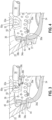
- a wind turbine 10 is shown and is constructed with a tower 12, a nacelle 14, and a rotor 16 coupled for rotation relative to the nacelle 14.
- the rotor 16 generally comprises a rotor hub 22 and three turbine blades 24 fixed for rotation with the rotor hub 22.
- the tower 12 includes a base 26 fixed to a support surface 28 which may, for example, be a foundation in the ground or any other suitable support surface including a platform at sea.
- the wind turbine 10 includes a braking system and control (not shown) which will be used to slow and then stop the rotor 16 from rotating.
- the control will be used to activate a rotor lock system that comprises a plurality of rotor locking pins 30 engageable and disengageable with a rotor locking disc 32 as further described below.
- the wind turbine 10 generally includes a main shaft 34 which is coupled to a generator directly or through other drive components (not shown).
- the main shaft 34 further includes a front end 34a.
- the front end 34a includes a first connecting structure 36.
- the rotor hub 22 includes a second connecting structure 40 configured to mate with the first connecting structure 36 on the front end 34a of the main shaft 34.
- These connecting structures 36, 40 are fixed rigidly together using one or more sets of threaded bolts 39a, 39b, 39c extending through respective holes 38a, 38b, 38c of the flange 37 and into large holes 44 and/or smaller holes (not shown) provided in the rotor hub 22 as will be described further below.
- the rotor locking disc 32 is carried on the main shaft 34 proximate the front end 34a. This may be accomplished in several different manners.
- the disc 32 may be comprised of one or more separate components sandwiched or located between or adjacent the flange 37 and the connecting structure 40 of the rotor hub 22 and thereby rigidly affixed between these two components using the same bolts 39a, 39b, 39c as used to connect the flange 37 to the rotor hub 22.
- the rotor locking disc 32 may be integrated onto an area proximate the front end 34a of the main shaft 34, such as by casting or otherwise forming the rotor locking disc 32 with the main shaft 34.
- One advantage of having the rotor locking disc 32 comprised of at least one separate component is that if the rotor locking system somehow damages the disc 32, the disc may be replaced and/or repaired without having to remove and replace the entire main shaft 34.
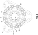
- the rotor locking disc 32 has an outer generally circular circumference 32a and a plurality of rotor locking elements in the form of recesses 50 having openings 50a on their perimeters that communicate with the outer circumference 32a.
- the rotor locking elements 50 may comprise any other configurations, such as conventional circular or other continuous or closed perimeter recesses.
- the recesses may be complete through bores or blind bores.
- At least one rotor locking pin 30 is movable in an axial direction parallel to the lengthwise axis of the main shaft 34.
- the pin 30 moves between a disengaged position relative to at least one of the recesses 50 and an engaged position at least partially located in one of the recesses 50 for locking the rotor hub 22 against rotation.
- the recesses 50 are shown as partially circular in shape and the pins 30 have a complementary cylindrical shape for closely extending at least partially into an aligned recess 50. Other shapes may be used instead.
- Two rotor locking pins 30, for example, may be located at the three o'clock and nine o'clock positions relative to the disc 32 and may be driven along their respective axes by suitable drive components (not shown) between extended and retracted positions.
- the pins 30 In the extended position, the pins 30 will have their ends at least partially received in a respective aligned recess 50 thereby locking the rotor hub 22 and main shaft 34 against any rotation.
- the pins 30 are part of a rotor locking system in the nacelle 14 ( Fig. 1 ) that is rigidly secured and fixed in place with components that are not shown for the sake of conciseness.
- these components of the rotor locking system are well known to those of skill in the art.
- the pins 30 In the retracted or disengaged position, the pins 30 will move along the same axial path as the engagement movement previously described but in the opposite direction. This disengagement will unlock disengage the recesses 50 and allow rotation of the rotor hub 22 and main shaft 34.
- the outer diameter of the rotor locking disc 32 is smaller than the outer diameter of a conventional rotor locking ring having closed perimeter recesses near the periphery for receiving rotor locking pins.
- embodiments having closed perimeter recesses also have advantages and will be described further below in connection with Fig. 5 .
- the reduction in diameter allowed by the use of open perimeter recesses 50 further increases accessibility to the rotor hub 22 and reduces weight of the rotor locking disc 32 while enabling optimization of strength and stress characteristics, as well as allowing more design freedom for the shape and configuration of the disc 32.
- the main shaft 34 includes a front end 34a including a flange 37 having a first connecting structure 36.
- the rotor hub 22 includes a second connecting structure 40.
- the first connecting structure 36 of the main shaft 34 is fixed to the second connecting structure 40 of the rotor hub 22.
- the first connecting structure 36 comprises at least first and second sets of fastener holes 38a, 38b in the peripheral region of the rotor locking disc 32.
- the rotor locking disc 32 in this embodiment, comprises an integral flange 37.
- the rotor locking disc 32 may instead be a separate component affixed to the main shaft 34.
- the rotor locking disc 32 is carried proximate the front end 34a of the main shaft 34.
- the rotor locking elements are respective recesses 50, as mentioned above, but these may be formed in any other configurations such as when combined with the sets of different sized fastener holes 38a, 38b and/or 38c.
- the first set of fastener holes 38a is located at a position radially inward of the rotor locking elements 50 and the second set of fastener holes 38b is located between adjacent rotor locking elements 50.
- the first and/or second sets of fastener holes 38a, 38b are used to receive fasteners 39a and/or 39b to secure the main shaft 34 to the rotor hub 22.
- a third set of fastener holes 38c are located in the peripheral region of the rotor locking disc 32 in this embodiment as well. Both the second and third sets of fastener holes 38b, 38c are located between adjacent rotor locking elements 50.
- the first set of fastener holes 38a comprise holes of larger diameter than the second and third sets of fastener holes 38b, 38c.
- the first set of fastener holes 38a are relatively larger sized to receive M48 bolts, while the second and third sets of fastener holes 38b, 38c are relatively smaller sized to receive M36 bolts.
- main shaft 34 configured with these three sets of circularly arranged holes 38a, 38b, 38c
- the same main shaft may be affixed to a first hub 22 using only the larger holes 38a and larger bolts 39a, or to another hub 22 having a different size and/or design configuration using all three sets of holes 38a, 38b, 38c and both large bolts 39a and smaller bolts 39b, 39c.
- the third set of fastener holes 38c are positioned radially outwards of the second set of fastener holes 38b, further combinations of the use of holes are possible dependent on which configuration is desired.
- the invention may include multiple sets of holes in which all holes have the same diameter.
- FIG. 5 A second illustrative embodiment of the invention is shown in Fig. 5 .
- This embodiment may be formed as described generally above in connection with the first embodiment, but may further include differences as shown and/or described with respect to Fig. 5 .
- the same reference numerals are used to describe common features or components with respect to the first embodiment and need no further detailed discussion.
- Features or components that are slightly different from analogous features or components of the first embodiment are denoted with the same reference numerals but also include prime ( ⁇ ) marks.
- the first connecting structure 36' comprises at least first and second sets of fastener holes 38a', 38b' in the peripheral region of the rotor locking disc 32.
- the rotor locking disc 32 in this second embodiment, comprises an integral flange 37.
- the rotor locking disc 32 may instead be a separate component affixed to the main shaft 34.
- the rotor locking disc 32 is carried proximate the front end 34a of the main shaft 34.
- the rotor locking elements are illustrated as respective closed perimeter recesses 50, but these may be formed in any other configuration(s) as described herein or otherwise.
- the first set of fastener holes 38a is located at a position radially inward of the rotor locking elements 50 and the second and third sets of fastener holes 38b', 38c' are located in the spaces of the locking disc 32 between adjacent rotor locking elements 50.
- fastener holes 38a, 38b', and 38c' each have the same diameter.
- the diameters may be of any desired or necessary size for the application. While there are advantages of using sets of fastener holes having different diameters as previously described herein, there are independent advantages of locating fastener holes between adjacent rotor locking elements 50. In this regard, the space between adjacent rotor locking elements 50 is efficiently used for connection purposes by placement of one or more fastener holes in these spaces, regardless of the size of the fastener holes and regardless of the particular design or configuration of the rotor locking elements.
- the first and/or second sets of fastener holes 38a, 38b' are used to receive suitable fasteners such as bolts to secure the main shaft 34 to the rotor hub 22.
- a third set of fastener holes 38c' are located in the peripheral region of the rotor locking disc 32 in this embodiment as well. Both the second and third sets of fastener holes 38b', 38c' are located in the material of the disc 32 between adjacent rotor locking elements 50.
- bolts 39a as described in the first embodiment may be used for securing the main shaft 34 to the rotor hub 22. In other situations, it may be necessary to use only the first set of fastener holes 38a and corresponding bolts 39a for securing the main shaft 34 to the rotor hub 22. If all holes 38a, 38b', 38c' have the same corresponding diameter, then bolts 39a may be used as necessary in each of the holes 38a, 38b', 38c'.
Landscapes
- Engineering & Computer Science (AREA)
- Life Sciences & Earth Sciences (AREA)
- Sustainable Development (AREA)
- Sustainable Energy (AREA)
- Chemical & Material Sciences (AREA)
- Combustion & Propulsion (AREA)
- Mechanical Engineering (AREA)
- General Engineering & Computer Science (AREA)
- Wind Motors (AREA)
Claims (7)
- Windkraftanlage (10), umfassend:eine Hauptantriebswelle (34), die ein vorderes Ende (34a) beinhaltet, wobei das vordere Ende (34a) eine erste Verbindungsstruktur (36, 36') beinhaltet;eine Rotornabe (22), die eine zweite Verbindungsstruktur (40) beinhaltet, wobei die erste Verbindungsstruktur (36, 36') der Hauptantriebswelle (34) an der zweiten Verbindungsstruktur (40) der Rotornabe (22) befestigt ist;eine Vielzahl von Blättern (24), die an die Rotornabe (22) gekoppelt sind;eine Rotorverriegelungsscheibe (32, 32'), die auf der Hauptantriebswelle (34) getragen wird, wobei die Rotorverriegelungsscheibe (32, 32') einen Randbereich und eine Vielzahl von Rotorverriegelungselementen (50) in dem Randbereich zum Aufnehmen eines oder mehrerer Rotorverriegelungsstifte (30) aufweist, die konfiguriert sind, um sich in einer axialen Richtung in Bezug zur Längsachse der Hauptantriebswelle (34) zu bewegen; undmindestens einen ersten und zweiten Satz an Befestigungslöchern (38a, 38b, 38b', 38c, 38c') im Randbereich der Rotorverriegelungsscheibe (32, 32'), wobei sich der erste Satz an Befestigungslöchern (38a) an einer Position radial innerhalb der Rotorverriegelungselemente (50) befindet und sich der zweite Satz an Befestigungslöchern (38b, 38b') zwischen benachbarten Rotorverriegelungselementen (50) befindet, wobei der erste und/oder zweite Satz an Befestigungslöchern (38a, 38b, 38b') verwendet wird, um Befestigungselemente (39a, 39b) aufzunehmen, um die Hauptantriebswelle (34) an der Rotornabe (22) zu sichern, dadurch gekennzeichnet, dass die Rotorverriegelungsscheibe (32, 32') in die Hauptantriebswelle (34) integriert ist.
- Windkraftanlage (10) nach Anspruch 1, weiter umfassend:
einen dritten Satz an Befestigungslöchern (38c, 38c') in dem Randbereich der Rotorverriegelungsscheibe (32, 32'), der radial außerhalb des zweiten Satzes an Befestigungslöchern (38b, 38b') positioniert ist, wobei sich beide, der zweite und dritte Satz an Befestigungslöchern (38b, 38b', 38c, 38c') zwischen benachbarten Rotorverriegelungselementen (50) befinden. - Windkraftanlage (10) nach Anspruch 1 oder 2, wobei mindestens ein Satz der Befestigungslöcher (38a, 38b, 38c) einen anderen Durchmesser als ein anderer Satz der Befestigungslöcher hat.
- Windkraftanlage (10) nach Anspruch 1 oder 2, wobei die Befestigungslöcher (38a, 38b', 38c') jedes Satzes den gleichen Durchmesser haben.
- Windkraftanlage (10) nach Anspruch 3, wobei der Satz oder die Sätze an Befestigungslöchern (38b, 38c), die sich zwischen den Rotorverriegelungselementen (50) befinden, einen kleineren Durchmesser als der erste Satz an Befestigungslöchern (38a) haben.
- Windkraftanlage (10) nach einem vorstehenden Anspruch, wobei die Rotorverriegelungselemente (50) weiter Aussparungen (50) umfassen, die Perimeter aufweisen, die sich zu einem Außenumfang (32a, 32a') der Rotorverriegelungsscheibe (32, 32') hin öffnen (50a).
- Windkraftanlage (10) nach einem vorstehenden Anspruch, wobei die Rotorverriegelungselemente (50) weiter Aussparungen (50) umfassen, die jeweils durch einen geschlossenen Perimeter definiert sind.
Applications Claiming Priority (2)
| Application Number | Priority Date | Filing Date | Title |
|---|---|---|---|
| DKPA201870713 | 2018-11-01 | ||
| PCT/DK2019/050299 WO2020088723A1 (en) | 2018-11-01 | 2019-10-09 | Wind turbine with modular main shaft fastening system and rotor locking disc |
Publications (3)
| Publication Number | Publication Date |
|---|---|
| EP3874147A1 EP3874147A1 (de) | 2021-09-08 |
| EP3874147B1 true EP3874147B1 (de) | 2024-12-25 |
| EP3874147C0 EP3874147C0 (de) | 2024-12-25 |
Family
ID=68295906
Family Applications (1)
| Application Number | Title | Priority Date | Filing Date |
|---|---|---|---|
| EP19790451.9A Active EP3874147B1 (de) | 2018-11-01 | 2019-10-09 | Windturbine mit modularem hauptwellenbefestigungssystem und rotorverriegelungsscheibe |
Country Status (5)
| Country | Link |
|---|---|
| US (1) | US11359603B2 (de) |
| EP (1) | EP3874147B1 (de) |
| CN (1) | CN112930441B (de) |
| ES (1) | ES2998499T3 (de) |
| WO (1) | WO2020088723A1 (de) |
Families Citing this family (2)
| Publication number | Priority date | Publication date | Assignee | Title |
|---|---|---|---|---|
| US20220397095A1 (en) * | 2021-06-09 | 2022-12-15 | General Electric Company | Hub-shaft bolted-joint connection of a wind turbine |
| CN113482865A (zh) * | 2021-08-19 | 2021-10-08 | 三一重能股份有限公司 | 一种风力发电机 |
Family Cites Families (16)
| Publication number | Priority date | Publication date | Assignee | Title |
|---|---|---|---|---|
| CN101328859B (zh) * | 2008-07-17 | 2010-06-02 | 无锡宝南机器制造有限公司 | 风力发电机的主轴 |
| DE102008036230B4 (de) * | 2008-08-02 | 2010-07-01 | Nordex Energy Gmbh | Verfahren zur Montage einer Rotornabe an einer Rotorwelle einer Windenergieanlage und Windenergieanlage |
| DE102008063043B4 (de) * | 2008-12-23 | 2010-10-28 | Aerodyn Engineering Gmbh | Arretierungsvorrichtung für den Rotor von Windenergieanlagen |
| US8556591B2 (en) * | 2010-04-21 | 2013-10-15 | General Electric Company | Systems and methods for assembling a rotor lock assembly for use in a wind turbine |
| KR101775373B1 (ko) | 2010-06-21 | 2017-09-06 | 엔비전 에너지 (덴마크) 에이피에스 | 가요성 샤프트 풍력 터빈 |
| AU2011310935A1 (en) * | 2011-09-22 | 2013-04-04 | Mitsubishi Heavy Industries, Ltd. | Power generating apparatus of renewable energy type and method of attaching and detaching blade |
| KR101397452B1 (ko) * | 2012-07-13 | 2014-05-20 | 삼성중공업 주식회사 | 풍력발전기의 로터락 제어 시스템 |
| KR20140072561A (ko) | 2012-12-05 | 2014-06-13 | 대우조선해양 주식회사 | 풍력발전기의 회전축 잠금장치 |
| CN103644082B (zh) * | 2013-11-14 | 2016-11-09 | 上海华仪风能电气有限公司 | 兆瓦级风力发电机风轮锁定装置 |
| CN205117615U (zh) * | 2015-10-16 | 2016-03-30 | 广东明阳风电产业集团有限公司 | 一种紧凑型风力发电机组的改进结构 |
| CN205638800U (zh) * | 2016-04-20 | 2016-10-12 | 广东明阳风电产业集团有限公司 | 一种紧凑型风力发电机组风轮锁定装置 |
| DK179196B1 (en) * | 2016-06-07 | 2018-01-29 | Envision Energy Denmark Aps | Wind turbine with a rotor locking system and a method thereof |
| EP3523535B1 (de) * | 2016-10-07 | 2021-09-08 | Vestas Wind Systems A/S | Rotorblockiersystem für eine windturbine |
| WO2018072796A1 (en) | 2016-10-20 | 2018-04-26 | Vestas Wind Systems A/S | Rotor restraining and rotating apparatus and method for wind turbines |
| ES2997487T3 (en) * | 2016-12-30 | 2025-02-17 | General Electric Renovables Espana Sl | Hub-to-shaft adapter for a rotor assembly of a wind turbine and related assembly methods |
| EP3385535A1 (de) * | 2017-04-07 | 2018-10-10 | Adwen GmbH | Rotorarretierungssystem |
-
2019
- 2019-10-09 EP EP19790451.9A patent/EP3874147B1/de active Active
- 2019-10-09 CN CN201980071440.7A patent/CN112930441B/zh active Active
- 2019-10-09 ES ES19790451T patent/ES2998499T3/es active Active
- 2019-10-09 US US17/285,229 patent/US11359603B2/en active Active
- 2019-10-09 WO PCT/DK2019/050299 patent/WO2020088723A1/en not_active Ceased
Also Published As
| Publication number | Publication date |
|---|---|
| CN112930441B (zh) | 2023-07-07 |
| US20210363967A1 (en) | 2021-11-25 |
| CN112930441A (zh) | 2021-06-08 |
| EP3874147C0 (de) | 2024-12-25 |
| WO2020088723A1 (en) | 2020-05-07 |
| EP3874147A1 (de) | 2021-09-08 |
| US11359603B2 (en) | 2022-06-14 |
| ES2998499T3 (en) | 2025-02-20 |
Similar Documents
| Publication | Publication Date | Title |
|---|---|---|
| EP1925820B1 (de) | Hauptlager einer Windkraftanlage | |
| US8912680B2 (en) | Wind power turbine rotary electric machine | |
| US10961985B2 (en) | Wind turbine and methods including main shaft integrated with locking disc | |
| CN108775273B (zh) | 变桨机构及风力发电机组 | |
| EP3874147B1 (de) | Windturbine mit modularem hauptwellenbefestigungssystem und rotorverriegelungsscheibe | |
| US11319924B2 (en) | Wind turbine with rotor locking system | |
| JP2009008085A (ja) | ターボ機械ロータディスクに装着されるブレードを軸方向に保持する装置 | |
| US20200332772A1 (en) | An assembly for a wind turbine, and method of operating an assembly for a wind turbine | |
| KR20170118824A (ko) | 로터 락과 대응 리셉터클을 갖는 요 브레이크 기구가 장착된 터빈 | |
| EP2896824B1 (de) | Bremssystem für einen Windturbinengenerator | |
| US20140064971A1 (en) | Stiffener plate for a wind turbine | |
| EP4102065B1 (de) | Nabe-welle-bolzenverbindung einer windturbine | |
| EP4156475B1 (de) | Rotorverriegelung für eine elektrische maschine | |
| EP2877740B1 (de) | Rahmen für eine elektrische drehmaschine einer windturbine und elektrische drehmaschine | |
| CN104214050B (zh) | 风力涡轮机凸缘连接 | |
| EP3563057B1 (de) | Naben-wellen-adapter für eine rotoranordnung einer windturbine und zugehörige montageverfahren | |
| US10472792B2 (en) | Tower flange for a wind turbine | |
| CN113195888A (zh) | 风力涡轮机的发电机-齿轮箱总成 | |
| US7407370B2 (en) | Axial and circumferential seal for stacked rotor and/or stator assembly | |
| US7537430B2 (en) | Stacked reaction steam turbine rotor assembly | |
| EP4549727A1 (de) | Windturbinenantrieb | |
| CN114207997B (zh) | 用于风力涡轮机的发电机的定子 | |
| CN109690075A (zh) | 用于风能设备的转子止动设备以及方法 | |
| CN120772995A (zh) | 动力涡轮转子拆卸装置及拆卸方法 | |
| CN104791191B (zh) | 风力涡轮机发电机的制动系统 |
Legal Events
| Date | Code | Title | Description |
|---|---|---|---|
| STAA | Information on the status of an ep patent application or granted ep patent |
Free format text: STATUS: UNKNOWN |
|
| STAA | Information on the status of an ep patent application or granted ep patent |
Free format text: STATUS: THE INTERNATIONAL PUBLICATION HAS BEEN MADE |
|
| PUAI | Public reference made under article 153(3) epc to a published international application that has entered the european phase |
Free format text: ORIGINAL CODE: 0009012 |
|
| STAA | Information on the status of an ep patent application or granted ep patent |
Free format text: STATUS: REQUEST FOR EXAMINATION WAS MADE |
|
| 17P | Request for examination filed |
Effective date: 20210422 |
|
| AK | Designated contracting states |
Kind code of ref document: A1 Designated state(s): AL AT BE BG CH CY CZ DE DK EE ES FI FR GB GR HR HU IE IS IT LI LT LU LV MC MK MT NL NO PL PT RO RS SE SI SK SM TR |
|
| DAV | Request for validation of the european patent (deleted) | ||
| DAX | Request for extension of the european patent (deleted) | ||
| STAA | Information on the status of an ep patent application or granted ep patent |
Free format text: STATUS: EXAMINATION IS IN PROGRESS |
|
| 17Q | First examination report despatched |
Effective date: 20230227 |
|
| GRAP | Despatch of communication of intention to grant a patent |
Free format text: ORIGINAL CODE: EPIDOSNIGR1 |
|
| STAA | Information on the status of an ep patent application or granted ep patent |
Free format text: STATUS: GRANT OF PATENT IS INTENDED |
|
| INTG | Intention to grant announced |
Effective date: 20240909 |
|
| GRAS | Grant fee paid |
Free format text: ORIGINAL CODE: EPIDOSNIGR3 |
|
| GRAA | (expected) grant |
Free format text: ORIGINAL CODE: 0009210 |
|
| STAA | Information on the status of an ep patent application or granted ep patent |
Free format text: STATUS: THE PATENT HAS BEEN GRANTED |
|
| AK | Designated contracting states |
Kind code of ref document: B1 Designated state(s): AL AT BE BG CH CY CZ DE DK EE ES FI FR GB GR HR HU IE IS IT LI LT LU LV MC MK MT NL NO PL PT RO RS SE SI SK SM TR |
|
| REG | Reference to a national code |
Ref country code: GB Ref legal event code: FG4D |
|
| REG | Reference to a national code |
Ref country code: CH Ref legal event code: EP |
|
| REG | Reference to a national code |
Ref country code: DE Ref legal event code: R096 Ref document number: 602019063996 Country of ref document: DE |
|
| REG | Reference to a national code |
Ref country code: IE Ref legal event code: FG4D |
|
| U01 | Request for unitary effect filed |
Effective date: 20250103 |
|
| U07 | Unitary effect registered |
Designated state(s): AT BE BG DE DK EE FI FR IT LT LU LV MT NL PT RO SE SI Effective date: 20250115 |
|
| REG | Reference to a national code |
Ref country code: ES Ref legal event code: FG2A Ref document number: 2998499 Country of ref document: ES Kind code of ref document: T3 Effective date: 20250220 |
|
| PG25 | Lapsed in a contracting state [announced via postgrant information from national office to epo] |
Ref country code: HR Free format text: LAPSE BECAUSE OF FAILURE TO SUBMIT A TRANSLATION OF THE DESCRIPTION OR TO PAY THE FEE WITHIN THE PRESCRIBED TIME-LIMIT Effective date: 20241225 |
|
| PG25 | Lapsed in a contracting state [announced via postgrant information from national office to epo] |
Ref country code: NO Free format text: LAPSE BECAUSE OF FAILURE TO SUBMIT A TRANSLATION OF THE DESCRIPTION OR TO PAY THE FEE WITHIN THE PRESCRIBED TIME-LIMIT Effective date: 20250325 |
|
| PG25 | Lapsed in a contracting state [announced via postgrant information from national office to epo] |
Ref country code: GR Free format text: LAPSE BECAUSE OF FAILURE TO SUBMIT A TRANSLATION OF THE DESCRIPTION OR TO PAY THE FEE WITHIN THE PRESCRIBED TIME-LIMIT Effective date: 20250326 |
|
| PG25 | Lapsed in a contracting state [announced via postgrant information from national office to epo] |
Ref country code: RS Free format text: LAPSE BECAUSE OF FAILURE TO SUBMIT A TRANSLATION OF THE DESCRIPTION OR TO PAY THE FEE WITHIN THE PRESCRIBED TIME-LIMIT Effective date: 20250325 |
|
| PG25 | Lapsed in a contracting state [announced via postgrant information from national office to epo] |
Ref country code: SM Free format text: LAPSE BECAUSE OF FAILURE TO SUBMIT A TRANSLATION OF THE DESCRIPTION OR TO PAY THE FEE WITHIN THE PRESCRIBED TIME-LIMIT Effective date: 20241225 |
|
| PG25 | Lapsed in a contracting state [announced via postgrant information from national office to epo] |
Ref country code: PL Free format text: LAPSE BECAUSE OF FAILURE TO SUBMIT A TRANSLATION OF THE DESCRIPTION OR TO PAY THE FEE WITHIN THE PRESCRIBED TIME-LIMIT Effective date: 20241225 |
|
| PG25 | Lapsed in a contracting state [announced via postgrant information from national office to epo] |
Ref country code: IS Free format text: LAPSE BECAUSE OF FAILURE TO SUBMIT A TRANSLATION OF THE DESCRIPTION OR TO PAY THE FEE WITHIN THE PRESCRIBED TIME-LIMIT Effective date: 20250425 |
|
| PG25 | Lapsed in a contracting state [announced via postgrant information from national office to epo] |
Ref country code: SK Free format text: LAPSE BECAUSE OF FAILURE TO SUBMIT A TRANSLATION OF THE DESCRIPTION OR TO PAY THE FEE WITHIN THE PRESCRIBED TIME-LIMIT Effective date: 20241225 |
|
| PG25 | Lapsed in a contracting state [announced via postgrant information from national office to epo] |
Ref country code: CZ Free format text: LAPSE BECAUSE OF FAILURE TO SUBMIT A TRANSLATION OF THE DESCRIPTION OR TO PAY THE FEE WITHIN THE PRESCRIBED TIME-LIMIT Effective date: 20241225 |
|
| PLBE | No opposition filed within time limit |
Free format text: ORIGINAL CODE: 0009261 |
|
| STAA | Information on the status of an ep patent application or granted ep patent |
Free format text: STATUS: NO OPPOSITION FILED WITHIN TIME LIMIT |
|
| 26N | No opposition filed |
Effective date: 20250926 |
|
| U20 | Renewal fee for the european patent with unitary effect paid |
Year of fee payment: 7 Effective date: 20251027 |
|
| PGFP | Annual fee paid to national office [announced via postgrant information from national office to epo] |
Ref country code: GB Payment date: 20251023 Year of fee payment: 7 |
|
| PGFP | Annual fee paid to national office [announced via postgrant information from national office to epo] |
Ref country code: ES Payment date: 20251118 Year of fee payment: 7 |