EP3874142B1 - Pale de rotor segmentée d'éolienne dotée d'une broche creuse s'étendant dans le sens de la corde - Google Patents
Pale de rotor segmentée d'éolienne dotée d'une broche creuse s'étendant dans le sens de la corde Download PDFInfo
- Publication number
- EP3874142B1 EP3874142B1 EP18804822.7A EP18804822A EP3874142B1 EP 3874142 B1 EP3874142 B1 EP 3874142B1 EP 18804822 A EP18804822 A EP 18804822A EP 3874142 B1 EP3874142 B1 EP 3874142B1
- Authority
- EP
- European Patent Office
- Prior art keywords
- chord
- wise
- extending pin
- edge end
- blade
- Prior art date
- Legal status (The legal status is an assumption and is not a legal conclusion. Google has not performed a legal analysis and makes no representation as to the accuracy of the status listed.)
- Active
Links
- 238000000034 method Methods 0.000 claims description 26
- 230000014759 maintenance of location Effects 0.000 claims description 14
- 239000000463 material Substances 0.000 claims description 8
- 239000011248 coating agent Substances 0.000 claims description 5
- 238000000576 coating method Methods 0.000 claims description 5
- 230000008901 benefit Effects 0.000 description 6
- 238000012986 modification Methods 0.000 description 3
- 230000004048 modification Effects 0.000 description 3
- 238000005452 bending Methods 0.000 description 2
- 239000002131 composite material Substances 0.000 description 2
- 229920000049 Carbon (fiber) Polymers 0.000 description 1
- 229910000831 Steel Inorganic materials 0.000 description 1
- 206010046798 Uterine leiomyoma Diseases 0.000 description 1
- 239000000853 adhesive Substances 0.000 description 1
- 230000001070 adhesive effect Effects 0.000 description 1
- 239000004917 carbon fiber Substances 0.000 description 1
- 230000008878 coupling Effects 0.000 description 1
- 238000010168 coupling process Methods 0.000 description 1
- 238000005859 coupling reaction Methods 0.000 description 1
- 239000000835 fiber Substances 0.000 description 1
- 239000011521 glass Substances 0.000 description 1
- 239000003365 glass fiber Substances 0.000 description 1
- 230000005484 gravity Effects 0.000 description 1
- 238000009434 installation Methods 0.000 description 1
- 201000010260 leiomyoma Diseases 0.000 description 1
- VNWKTOKETHGBQD-UHFFFAOYSA-N methane Chemical compound C VNWKTOKETHGBQD-UHFFFAOYSA-N 0.000 description 1
- 238000000465 moulding Methods 0.000 description 1
- 230000008569 process Effects 0.000 description 1
- 230000002787 reinforcement Effects 0.000 description 1
- 230000008439 repair process Effects 0.000 description 1
- 239000010959 steel Substances 0.000 description 1
Images


Classifications
-
- F—MECHANICAL ENGINEERING; LIGHTING; HEATING; WEAPONS; BLASTING
- F03—MACHINES OR ENGINES FOR LIQUIDS; WIND, SPRING, OR WEIGHT MOTORS; PRODUCING MECHANICAL POWER OR A REACTIVE PROPULSIVE THRUST, NOT OTHERWISE PROVIDED FOR
- F03D—WIND MOTORS
- F03D1/00—Wind motors with rotation axis substantially parallel to the air flow entering the rotor
- F03D1/06—Rotors
- F03D1/065—Rotors characterised by their construction elements
- F03D1/0675—Rotors characterised by their construction elements of the blades
-
- F—MECHANICAL ENGINEERING; LIGHTING; HEATING; WEAPONS; BLASTING
- F05—INDEXING SCHEMES RELATING TO ENGINES OR PUMPS IN VARIOUS SUBCLASSES OF CLASSES F01-F04
- F05B—INDEXING SCHEME RELATING TO WIND, SPRING, WEIGHT, INERTIA OR LIKE MOTORS, TO MACHINES OR ENGINES FOR LIQUIDS COVERED BY SUBCLASSES F03B, F03D AND F03G
- F05B2230/00—Manufacture
- F05B2230/60—Assembly methods
-
- F—MECHANICAL ENGINEERING; LIGHTING; HEATING; WEAPONS; BLASTING
- F05—INDEXING SCHEMES RELATING TO ENGINES OR PUMPS IN VARIOUS SUBCLASSES OF CLASSES F01-F04
- F05B—INDEXING SCHEME RELATING TO WIND, SPRING, WEIGHT, INERTIA OR LIKE MOTORS, TO MACHINES OR ENGINES FOR LIQUIDS COVERED BY SUBCLASSES F03B, F03D AND F03G
- F05B2240/00—Components
- F05B2240/20—Rotors
- F05B2240/30—Characteristics of rotor blades, i.e. of any element transforming dynamic fluid energy to or from rotational energy and being attached to a rotor
- F05B2240/302—Segmented or sectional blades
-
- F—MECHANICAL ENGINEERING; LIGHTING; HEATING; WEAPONS; BLASTING
- F05—INDEXING SCHEMES RELATING TO ENGINES OR PUMPS IN VARIOUS SUBCLASSES OF CLASSES F01-F04
- F05B—INDEXING SCHEME RELATING TO WIND, SPRING, WEIGHT, INERTIA OR LIKE MOTORS, TO MACHINES OR ENGINES FOR LIQUIDS COVERED BY SUBCLASSES F03B, F03D AND F03G
- F05B2260/00—Function
- F05B2260/30—Retaining components in desired mutual position
- F05B2260/301—Retaining bolts or nuts
-
- Y—GENERAL TAGGING OF NEW TECHNOLOGICAL DEVELOPMENTS; GENERAL TAGGING OF CROSS-SECTIONAL TECHNOLOGIES SPANNING OVER SEVERAL SECTIONS OF THE IPC; TECHNICAL SUBJECTS COVERED BY FORMER USPC CROSS-REFERENCE ART COLLECTIONS [XRACs] AND DIGESTS
- Y02—TECHNOLOGIES OR APPLICATIONS FOR MITIGATION OR ADAPTATION AGAINST CLIMATE CHANGE
- Y02E—REDUCTION OF GREENHOUSE GAS [GHG] EMISSIONS, RELATED TO ENERGY GENERATION, TRANSMISSION OR DISTRIBUTION
- Y02E10/00—Energy generation through renewable energy sources
- Y02E10/70—Wind energy
- Y02E10/72—Wind turbines with rotation axis in wind direction
Definitions
- the present disclosure relates generally to wind turbines, and more particularly to a wind turbine jointed rotor blade having a hollow chord-wise extending pin.
- a modem wind turbine typically includes a tower, a generator, a gearbox, a nacelle, and a rotor having a rotatable hub with one or more rotor blades.
- the rotor blades capture kinetic energy of wind using known airfoil principles.
- the rotor blades transmit the kinetic energy in the form of rotational energy so as to turn a shaft coupling the rotor blades to a gearbox, or if a gearbox is not used, directly to the generator.
- the generator then converts the mechanical energy to electrical energy that may be deployed to a utility grid.
- the rotor blades generally include a suction side shell and a pressure side shell typically formed using molding processes that are bonded together at bond lines along the leading and trailing edges of the blade.
- the pressure and suction shells are relatively lightweight and have structural properties (e.g., stiffness, buckling resistance and strength) which are not configured to withstand the bending moments and other loads exerted on the rotor blade during operation.
- the body shell is typically reinforced using one or more structural components (e.g. opposing spar caps with a shear web configured therebetween) that engage the inner pressure and suction side surfaces of the shell halves.
- the spar caps and/or shear web may be constructed of various materials, including but not limited to glass fiber laminate composites and/or carbon fiber laminate composites.
- larger rotor blades may be constructed in segments that can be assembled on site via one or more pin joints.
- Increasing the blade length requires additional blade support, because gravity pulls along the increased length to create a larger bending moment than in shorter rotor blades.
- the pin joints are configured to allow the blade tip to flex to withstand some of this load.
- Such point joints can add weight to the rotor blade and can cause issues with the structural integrity of the rotor blade if not properly designed.
- Segmented rotor blades for wind turbines are known, for example, from US 2011/020126 A1 , US 2018/274521 A1 , and US 2017/268482 A1 .
- the present disclosure is directed to an improved wind turbine jointed rotor blade having a structurally-reinforced hollow chord-wise extending pin so as to minimize mass of the joint, while also providing improved installation and optimized material usage.
- the structurally-reinforced hollow chord-wise extending pin also prevents ovalization that could occur in a hollow tube design alone.
- the present disclosure is directed to a rotor blade for a wind turbine.
- the rotor blade includes a first blade segment and a second blade segment extending in opposite directions from a chord-wise joint.
- Each of the first and second blade segments includes at least one shell member defining an airfoil surface and an internal support structure.
- the first blade segment includes a beam structure extending lengthwise that structurally connects with the second blade segment via a receiving section.
- the rotor blade also includes at least one chord-wise extending pin positioned through the chord-wise joint so as to secure the first and second blade segments together.
- the chord-wise extending pin includes a hollow cross-section that extends from a trailing edge end to a leading edge end thereof.
- the chord-wise extending pin may define a first outer diameter that begins at the trailing edge end and a second outer diameter that ends at the leading edge end. Further, the first outer diameter may be larger than the second outer diameter. Moreover, the first outer diameter may taper to the second outer diameter at a transitional region of the chord-wise extending pin.
- the chord-wise extending pin may extend through a plurality of bushings provided in the internal support structures of the first and second blade segments.
- the chord-wise extending pin includes a plurality of structural inserts arranged within the hollow cross-section.
- the chord-wise extending pin may include a first structural insert arranged at the trailing edge end thereof and a second structural insert arranged at the leading edge end thereof. The structural inserts may align with the plurality of bushings.
- the chord-wise extending pin may further include a coating material between the chord-wise extending pin and one or more of the plurality of bushings and/or between the plurality of bushings so as to decrease friction.
- a trailing edge bushing of the plurality of bushings may extend beyond a surface of the chord-wise joint to allow an additional retention feature to be secured thereto.
- the chord-wise extending pin may include a threaded center hole that extends from the trailing edge end to the leading edge end thereof.
- chord-wise extending pin may include one or more retention features arranged at one or both of the trailing edge end or the leading edge end thereof.
- the retention feature(s) may include a retention ring and/or a closed-end bushing.
- chord-wise extending pin may be constructed of a plurality of pin segments secured together, e.g. at a low-stress location of the pin.
- the present disclosure is directed to a non-claimed rotor blade for a wind turbine.
- the rotor blade includes a first blade segment and a second blade segment extending in opposite directions from a chord-wise joint.
- Each of the first and second blade segments includes at least one shell member defining an airfoil surface and an internal support structure.
- the first blade segment includes a beam structure extending lengthwise that structurally connects with the second blade segment via a receiving section.
- the rotor blade also includes at least one chord-wise extending pin positioned through the chord-wise joint so as to secure the first and second blade segments together.
- the chord-wise extending pin defines a first outer diameter that begins at a trailing edge end thereof and a second outer diameter that ends at a leading edge end thereof. Further, the first outer diameter is larger than the second outer diameter. Moreover, the first outer diameter tapers to the second outer diameter at a transitional region of the chord-wise extending pin.
- the present disclosure is directed to a method of joining first and second blade segments of a rotor blade of a wind turbine.
- the method includes providing the first blade segment having a beam structure that extends in a generally span-wise direction.
- the method also includes providing the second blade segment having a receiving section that extends in the generally span-wise direction.
- the method includes inserting the beam structure of the first blade segment into the receiving section of the second blade segment such that the first and second blade segments extend in opposite directions from a chord-wise joint.
- Each of the first and second blade segments has a pressure side shell member and a suction side shell member.
- the method includes inserting a chord-wise extending pin through the chord-wise joint so as to secure the first and second blade segments together.
- the chord-wise extending pin also includes a hollow cross-section that extends from a trailing edge end to a leading edge end thereof. It should be understood that the method may further include any of the additional features and/or steps as described herein.
- inserting the chord-wise extending pin through the chord-wise joint may include inserting the leading edge end of the chord-wise extending pin through a plurality of bushings provided in the internal support structures of the first and second blade segments. More specifically, inserting the chord-wise extending pin through the chord-wise joint may include engaging the first outer diameter of the trailing edge end of the chord-wise extending pin with one or more trailing edge bushings before the leading edge end of the chord-wise extending pin is inserted into one or more leading edge bushings.
- FIG. 1 illustrates a perspective view of one embodiment of a wind turbine 10 according to the present invention.
- the wind turbine 10 is a horizontal-axis wind turbine.
- the wind turbine 10 may be a vertical-axis wind turbine.
- the wind turbine 10 may include a tower 12 that extends from a support surface 14, a nacelle 16 mounted on the tower 12, a generator 18 positioned within the nacelle 16, a gearbox 20 coupled to the generator 18, and a rotor 22 that is rotationally coupled to the gearbox 20 with a rotor shaft 24.
- the rotor 22 includes a rotatable hub 26 and at least one rotor blade 28 coupled to and extending outward from the rotatable hub 26.
- the rotor blade 28 includes a blade tip 17 and a blade root 19.
- the rotor blade 28 may include a first blade segment 30 and a second blade segment 32. Further, as shown, the first blade segment 30 and the second blade segment 32 may each extend in opposite directions from a chord-wise joint 34. In addition, as shown, each of the blade segments 30, 32 may include a pressure side shell member and a suction side shell member. The first blade segment 30 and the second blade segment 32 are connected by at least an internal support structure 36 extending into both blade segments 30, 32 to facilitate joining of the blade segments 30, 32.
- the arrow 38 shows that the segmented rotor blade 28 in the illustrated example includes two blade segments 30, 32 and that these blade segments 30, 32 are joined by inserting the internal support structure 36 into the second blade segment 32.
- the second blade segment includes multiple spar structures 66 (also referred to herein as spar caps) that extend lengthwise for connecting with a blade root section 35 of the rotor blade 28 (which is shown in more detail in FIG. 7 ) and with the beam structure 40 of the first blade segment 30 (which is shown in more detail in FIG. 5 ).
- the first blade segment 30 includes a beam structure 40 that forms a portion of the internal support structure 36 and extends lengthwise for structurally connecting with the second blade segment 32. Further, as shown, the beam structure 40 forms a part of the first blade segment 30 having an extension protruding from a spar section 42, thereby forming an extending spar section.
- the beam structure 40 includes a shear web 44 connected with a suction side spar cap 46 and a pressure side spar cap 48.
- the first blade segment 30 may include one or more first pin joints at a first end 54 of the beam structure 40.
- the pin joint may include a pin that is in a tight interference fit with a bushing.
- the pin joint(s) may include one pin tube 52 located on the beam structure 40.
- the pin tube 52 may be oriented in a span-wise direction.
- the first blade segment 30 may also include a pin joint slot 50 located on the beam structure 40 at the chord-wise joint 34.
- the pin joint slot 50 may be oriented in a chord-wise direction.
- the second blade segment 32 includes a receiving section 60 extending lengthwise within the second blade segment 32 for receiving the beam structure 40 of the first blade segment 30.
- the receiving section 60 may include the spar structures 66 that extend lengthwise for connecting with the beam structure 40 of the first blade segment 30.
- the assembly 70 illustrates multiple supporting structures beneath outer shell members of the rotor blade 28 having the first blade segment 30 joined with the second blade segment 32.
- the receiving section 60 includes the multiple spar structures 66 extending lengthwise and supports the beam structure 40.
- the receiving section 60 also includes a rectangular fastening element 72 that connects with the pin tube 52 of the beam structure 40 in the span-wise direction.
- the first and the second blade segments 30, 32 may also include chord-wise members 74, 76 respectively at the chord-wise joint 34.
- each of the spar structures 66, the rectangular fastening element 72, and the chord-wise members 74, 76 may be constructed of glass reinforced fibers.
- the pair of spar structures 66 is configured to receive the beam structure 40 and may include pin joint slots 82, 84 that are aligned with the pin joint slot 50 of the beam structure 40 through which a chord-wise extending 62 may be inserted. Further, as shown, the chord-wise extending 62 may be configured to remain in a tight interference fit within the aligning pin joint slots 82, 50, 84 such that spar structures 66 and the beam structure 40 are joined together during assembly. Further, FIG. 6 also illustrates the rectangular fastening element 72 that includes a pin joint slot 86 configured for receiving the pin tube 52 of the beam structure 40. As such, the pin tube 52 is configured to form a tight interference fit pined joint. Further, the pair of spar structures 66 may be joined together at one end 88 using any suitable adhesive material or an elastomeric seal.
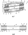
- FIGS. 7-10 various views of the chord-wise extending pin 62 according to the present disclosure are illustrated. More particularly, FIG. 7 illustrates a cross-sectional view of the chord-wise joint 34 of FIG. 5 along section line 7-7 is illustrated.
- the chord-wise extending pin 62 is positioned through the chord-wise joint 34 so as to secure the internal support structures 40, 60 of the first and second blade segments 30, 32 together. More specifically, as shown, the chord-wise extending pin 62 may extend through a plurality of bushings 55, 56, 57, 58 provided in the internal support structures 40, 60 of the first and second blade segments 30, 32.
- the beam structure 40 and the receiving section 60 may each include leading and trailing edge bushings 55, 56, 57, 58, respectively, that receive the chord-wise extending pin 62.
- each of the bushings 55, 56, 57, 58 may include a flange 61, 63, 65, 67 that abuts against an adjacent bushing.
- the chord-wise extending pin 62 includes a hollow cross-section 64 that extends from a trailing edge end 68 to a leading edge end 69 thereof. More specifically, as shown particularly in FIGS. 9A, 9B, and 9C , the chord-wise extending pin 62 may define a first outer diameter 71 that begins at the trailing edge end 68 and a second outer diameter 73 that ends at the leading edge end 69. Further, as shown, the first outer diameter 71 is larger than the second outer diameter 73. Moreover, as shown, the first outer diameter 71 may taper to the second outer diameter 73 at a transitional region 78 of the chord-wise extending pin 62. In addition, as shown in FIG.
- the chord-wise extending pin 62 may further taper from the second outer diameter 73 to a smaller outer diameter 75 at the leading edge end 69.
- the chord-wise extending pin 62 may include a threaded center hole 77 that extends from the trailing edge end 68 to the leading edge end 69 thereof.
- the chord-wise extending pin 62 includes a plurality of structural inserts 80, 81 arranged within the hollow cross-section 64.
- the chord-wise extending pin 62 may include a first structural insert 80 arranged at the trailing edge end 68 thereof and a second structural insert 81 arranged at the leading edge end 69 thereof.
- the structural insert(s) 80, 81 may be aligned with the bushings 55, 56, 57, 58 when inserted into the hollow cross-section 64 of the chord-wise extending pin 62.
- the structural inserts 80, 81 may be steel inserts that are pressed into the pin 62 to provide additional reinforcement in high loading regions.
- the chord-wise extending pin 62 may also include one or more retention features 90, 92 arranged at one or both of the trailing edge end 68 or the leading edge end 69 thereof.
- the retention feature(s) 90, 92 may include a retention ring 90 (i.e. at the trailing edge end 68) and/or a closed-end bushing 92 (i.e. at the leading edge end 69).
- the chord-wise extending pin 62 of the present disclosure may be constructed of a plurality of pin segments 94 secured together, e.g. at a low-stress location of the pin 62.
- one of the pin segments 94 may include at least one pin screw 95 for securing the pin segments 94 together.
- the chord-wise extending pin 62 may include one or more retention features 96 built into the pin 62. Accordingly, the segmented design allows for easier removal of the pin 62, e.g. during repairs, with enlarged end diameters to provide a securable area.
- the chord-wise extending pin 62 of the present disclosure may further include a coating material 98 between the chord-wise extending pin 62 and the bushings 55, 56, 57, 58 and/or between each of the bushings 55, 56, 57, 58 so as to decrease friction therebetween.
- a coating material 98 between the chord-wise extending pin 62 and the bushings 55, 56, 57, 58 and/or between each of the bushings 55, 56, 57, 58 so as to decrease friction therebetween.
- fibroids may surround at least a portion of the outer diameter of the pin 62 or an inner diameter of the bushings 55, 56, 57, 58.
- a diamond-like coating (DCL) material may be applied to the pin 62, i.e. to increase hardness and/or decrease friction within the bushings 55, 56, 57, 58.
- the trailing edge bushing 56 of the chord-wise extending pin 62 of the present disclosure may be threaded.
- the threaded trailing edge bushing 56 i.e. of the receiving section 60, may extend out from a surface thereof so to allow an additional threaded cap (not shown) to be secured thereon.
- FIG. 14 a flow chart 100 of a method of joining first and second blade segments of a rotor blade of a wind turbine according to the present disclosure is illustrated.
- the method 100 will be described herein with reference to the wind turbine 10 and the rotor blade 28 shown in FIGS. 1-13 .
- the disclosed method 100 may be implemented with rotor blades having any other suitable configurations.
- FIG. 14 depicts steps performed in a particular order for purposes of illustration and discussion, the methods discussed herein are not limited to any particular order or arrangement.
- steps of the methods disclosed herein can be omitted, rearranged, combined, and/or adapted in various ways without deviating from the scope of the present disclosure.
- the method 100 may include providing the first blade segment 30 having the beam structure 40 that extends in a generally span-wise direction.
- the method 100 may include providing the second blade segment 32 having the receiving section 60 that extends in the generally span-wise direction.
- the method 100 may include inserting the beam structure 40 of the first blade segment 30 into the receiving section 60 of the second blade segment 32 such that the first and second blade segments 30, 32 extend in opposite directions from the chord-wise joint 34.
- the method 100 may include inserting the chord-wise extending pin(s) 62 through the chord-wise joint 34 so as to secure the first and second blade segments 30, 32 together.
- the chord-wise extending pin 62 also includes a hollow cross-section 64 that extends from the trailing edge end 68 to the leading edge end 69 thereof.
- inserting the chord-wise extending pin 62 through the chord-wise joint 34 may include inserting the leading edge end 69 of the chord-wise extending pin 62 through the bushings 55, 56, 57, 58 provided in the internal support structures 40, 60 of the first and second blade segments 30, 32. More specifically, as shown, the first outer diameter 71 of the trailing edge end 68 of the chord-wise extending pin 62 may be engaged with the trailing edge bushings 57, 58 before the leading edge end 69 of the chord-wise extending pin 62 is inserted into the leading edge bushings 55, 56.
- the pin 62 may be fully engaged with the trailing edge bushings 57, 58 before trying to engage the leading edge bushings 55, 56, which assists in properly aligning the pin 62 before inserting the pin 62 into the leading edge bushings 55, 56.
Landscapes
- Engineering & Computer Science (AREA)
- Life Sciences & Earth Sciences (AREA)
- Sustainable Development (AREA)
- Sustainable Energy (AREA)
- Chemical & Material Sciences (AREA)
- Combustion & Propulsion (AREA)
- Mechanical Engineering (AREA)
- General Engineering & Computer Science (AREA)
- Wind Motors (AREA)
Claims (13)
- Pale de rotor (28) pour une éolienne, comportant :un premier segment de pale (30) et un deuxième segment de pale (32) s'étendant dans des directions opposées depuis un joint dans le sens de la corde (34), chacun des premier et deuxième segments de pale comportant au moins un élément de coque définissant une surface à profil aérodynamique et une structure de support interne (36, 40, 60), le premier segment de pale comportant une structure de poutre (40) s'étendant dans le sens de la longueur qui se relie structurellement avec le deuxième segment de pale par le biais d'une section de réception (60) ; etau moins une broche s'étendant dans le sens de la corde (62) positionnée au travers du joint dans le sens de la corde de manière à assujettir les premier et deuxième segments de pale ensemble, la broche s'étendant dans le sens de la corde comportant une section transversale creuse (64) qui s'étend depuis une extrémité de bord de fuite (68) jusqu'à une extrémité de bord d'attaque (69) de celle-ci, caractérisée en ce que la broche s'étendant dans le sens de la corde comporte par ailleurs une pluralité de pièces rapportées de structure (80, 81) agencées à l'intérieur de la section transversale creuse, dans laquelle une première pièce rapportée de structure (80) de la pluralité de pièces rapportées de structure est agencée au niveau de l'extrémité de bord de fuite de celle-ci et une deuxième pièce rapportée de structure (81) de la pluralité de pièces rapportées de structure est agencée au niveau de l'extrémité de bord d'attaque de celle-ci.
- Pale de rotor selon la revendication 1, dans laquelle la broche s'étendant dans le sens de la corde définit un premier diamètre extérieur (71) qui commence au niveau de l'extrémité de bord de fuite et un deuxième diamètre extérieur (73) qui se termine au niveau de l'extrémité de bord d'attaque, le premier diamètre extérieur étant supérieur au deuxième diamètre extérieur, le premier diamètre extérieur allant en s'effilant jusqu'au deuxième diamètre extérieur au niveau d'une région de transition (78) de la broche s'étendant dans le sens de la corde.
- Pale de rotor selon la revendication 1, dans laquelle la broche s'étendant dans le sens de la corde s'étend au travers d'une pluralité de bagues (55, 56, 57, 58) mises en oeuvre dans les structures de support internes des premier et deuxième segments de pale.
- Pale de rotor selon la revendication 3, dans laquelle les pièces rapportées de la pluralité de pièces rapportées de structure agencées à l'intérieur de la section transversale creuse sont alignées sur la pluralité de bagues.
- Pale de rotor selon la revendication 3, comportant par ailleurs un matériau de revêtement (98) entre au moins l'une parmi la broche s'étendant dans le sens de la corde et une ou plusieurs de la pluralité de bagues ou entre la pluralité de bagues de manière à réduire tout frottement.
- Pale de rotor selon la revendication 3, dans laquelle une bague de bord de fuite de la pluralité de bagues s'étend au-delà d'une surface du joint dans le sens de la corde pour permettre à un élément de retenue supplémentaire d'être assujetti sur celle-ci.
- Pale de rotor selon la revendication 1, dans laquelle la broche s'étendant dans le sens de la corde comporte par ailleurs un trou central fileté (77) qui s'étend depuis l'extrémité de bord de fuite jusqu'à l'extrémité de bord d'attaque de celle-ci.
- Pale de rotor selon la revendication 1, dans laquelle la broche s'étendant dans le sens de la corde comporte par ailleurs un ou plusieurs éléments de retenue (90, 92) agencés au niveau de l'une ou des deux parmi l'extrémité de bord de fuite ou l'extrémité de bord d'attaque de celle-ci.
- Pale de rotor selon la revendication 8, dans laquelle lesdits un ou plusieurs éléments de retenue comportent au moins un élément parmi un anneau de retenue (90) ou une bague à extrémité fermée (92).
- Pale de rotor selon la revendication 1, dans laquelle la broche s'étendant dans le sens de la corde est construite à partir d'une pluralité de segments de broche (94) assujettis ensemble.
- Procédé d'assemblage de premier et deuxième segments de pale (30 32) d'une pale de rotor (28) d'une éolienne, le procédé comportant les étapes consistant à :mettre en oeuvre le premier segment de pale (30) ayant une structure de poutre (40) qui s'étend dans une direction allant généralement dans le sens de l'envergure ;mettre en oeuvre le deuxième segment de pale (32) ayant une section de réception (60) qui s'étend dans la direction allant généralement dans le sens de l'envergure ;insérer la structure de poutre du premier segment de pale jusque dans la section de réception du deuxième segment de pale de telle sorte que les premier et deuxième segments de pale s'étendent dans des directions opposées depuis un joint dans le sens de la corde (34), chacun des premier et deuxième segments de pale ayant un élément de coque côté en pression et un élément de coque côté en dépression ; etinsérer une broche s'étendant dans le sens de la corde (62) au travers du joint dans le sens de la corde de manière à assujettir les premier et deuxième segments de pale ensemble, la broche s'étendant dans le sens de la corde comportant une section transversale creuse (64) qui s'étend depuis une extrémité de bord de fuite (68) jusqu'à une extrémité de bord d'attaque (69) de celle-ci, caractérisé en ce que la broche s'étendant dans le sens de la corde comporte par ailleurs une pluralité de pièces rapportées de structure (80, 81) agencées à l'intérieur de la section transversale creuse, dans lequel une première pièce rapportée de structure (80) de la pluralité de pièces rapportées de structure est agencée au niveau de l'extrémité de bord de fuite de celle-ci et une deuxième pièce rapportée de structure (81) de la pluralité de pièces rapportées de structure est agencée au niveau de l'extrémité de bord d'attaque de celle-ci.
- Procédé selon la revendication 11, dans lequel la broche s'étendant dans le sens de la corde définit un premier diamètre extérieur (71) qui commence au niveau de l'extrémité de bord de fuite et un deuxième diamètre extérieur (73) qui se termine au niveau de l'extrémité de bord d'attaque, le premier diamètre extérieur étant supérieur au deuxième diamètre extérieur, le premier diamètre extérieur allant en s'effilant jusqu'au deuxième diamètre extérieur au niveau d'une région de transition (78) de la broche s'étendant dans le sens de la corde.
- Procédé selon la revendication 12, dans lequel l'étape consistant à insérer la broche s'étendant dans le sens de la corde au travers du joint dans le sens de la corde comporte par ailleurs l'étape consistant à :
effectuer une mise en prise du premier diamètre extérieur de l'extrémité de bord de fuite de la broche s'étendant dans le sens de la corde avec une ou plusieurs bagues de bord de fuite (57, 58) avant que l'extrémité de bord d'attaque de la broche s'étendant dans le sens de la corde ne soit insérée jusque dans une ou plusieurs bagues de bord d'attaque (55, 56).
Applications Claiming Priority (1)
| Application Number | Priority Date | Filing Date | Title |
|---|---|---|---|
| PCT/US2018/058666 WO2020091784A1 (fr) | 2018-11-01 | 2018-11-01 | Pale de rotor articulée d'éolienne dotée d'une broche creuse s'étendant dans le sens de la corde |
Publications (2)
| Publication Number | Publication Date |
|---|---|
| EP3874142A1 EP3874142A1 (fr) | 2021-09-08 |
| EP3874142B1 true EP3874142B1 (fr) | 2023-12-27 |
Family
ID=64362698
Family Applications (1)
| Application Number | Title | Priority Date | Filing Date |
|---|---|---|---|
| EP18804822.7A Active EP3874142B1 (fr) | 2018-11-01 | 2018-11-01 | Pale de rotor segmentée d'éolienne dotée d'une broche creuse s'étendant dans le sens de la corde |
Country Status (9)
| Country | Link |
|---|---|
| US (1) | US11668277B2 (fr) |
| EP (1) | EP3874142B1 (fr) |
| JP (1) | JP7221384B2 (fr) |
| CN (1) | CN112912615A (fr) |
| AU (1) | AU2018448000A1 (fr) |
| CA (1) | CA3117310A1 (fr) |
| DK (1) | DK3874142T3 (fr) |
| MX (1) | MX2021004920A (fr) |
| WO (1) | WO2020091784A1 (fr) |
Families Citing this family (2)
| Publication number | Priority date | Publication date | Assignee | Title |
|---|---|---|---|---|
| GB202018692D0 (en) * | 2020-11-27 | 2021-01-13 | Lm Wp Patent Holding As | A mechanism for restraining movement of a locking pin |
| US20230082462A1 (en) * | 2021-09-15 | 2023-03-16 | Dupont Polymers, Inc. | Connecting structure of segmented wind turbine blades |
Family Cites Families (72)
| Publication number | Priority date | Publication date | Assignee | Title |
|---|---|---|---|---|
| US851196A (en) | 1907-04-23 | American British Mfg Company | Automatic gun. | |
| US4359913A (en) * | 1978-06-22 | 1982-11-23 | Amsted Industries Incorporated | Piston pin assembly |
| US4474536A (en) | 1980-04-09 | 1984-10-02 | Gougeon Brothers, Inc. | Wind turbine blade joint assembly and method of making wind turbine blades |
| DE3113079C2 (de) | 1981-04-01 | 1985-11-21 | Messerschmitt-Bölkow-Blohm GmbH, 8000 München | Aerodynamischer Groß-Flügel und Verfahren zu dessen Herstellung |
| US5281454A (en) | 1991-08-16 | 1994-01-25 | Kaiser Aerospace & Electronics Corporation | Closed composite sections with bonded scarf joints |
| FR2710871B1 (fr) | 1993-10-07 | 1995-12-01 | France Etat Armement | Procédé d'assemblage d'éléments en matériau composite et éléments assemblages entre eux. |
| DE10235496B4 (de) | 2002-08-02 | 2015-07-30 | General Electric Co. | Verfahren zum Herstellen eines Rotorblattes, Rotorblatt und Windenergieanlage |
| EP1584817A1 (fr) | 2004-04-07 | 2005-10-12 | Gamesa Eolica, S.A. (Sociedad Unipersonal) | Pale d'éolienne |
| CN102287322B (zh) | 2004-06-30 | 2015-12-16 | 维斯塔斯风力系统有限公司 | 由两个分离的部分制成的风轮机叶片以及装配方法 |
| US7344360B2 (en) | 2004-09-29 | 2008-03-18 | General Electric Company | Wind turbine rotor blade with in-plane sweep and devices using same, and methods for making same |
| US8544800B2 (en) | 2005-07-21 | 2013-10-01 | The Boeing Company | Integrated wingtip extensions for jet transport aircraft and other types of aircraft |
| US7654799B2 (en) | 2006-04-30 | 2010-02-02 | General Electric Company | Modular rotor blade for a wind turbine and method for assembling same |
| ES2319599B1 (es) | 2007-01-08 | 2010-01-26 | Guillermo Petri Larrea | Sistema reversible de seccionamiento en varias piezas de palas de aerogeneradores. |
| EP2033769A1 (fr) | 2007-09-04 | 2009-03-11 | Lm Glasfiber A/S | Procédé pour la fabrication d'une structure composite via des produits intermédiaires et structure composite pouvant être obtenue selon le procédé |
| GB0717690D0 (en) | 2007-09-11 | 2007-10-17 | Blade Dynamics Ltd | Wind turbine blade |
| ES2337645B1 (es) | 2007-09-14 | 2011-03-11 | GAMESA INNOVATION & TECHNOLOGY, S.L. | Union de pala sensorizada. |
| US8123488B2 (en) | 2007-09-17 | 2012-02-28 | General Electric Company | System and method for joining turbine blades |
| US8221085B2 (en) | 2007-12-13 | 2012-07-17 | General Electric Company | Wind blade joint bonding grid |
| US7740453B2 (en) | 2007-12-19 | 2010-06-22 | General Electric Company | Multi-segment wind turbine blade and method for assembling the same |
| DE102007061318B3 (de) | 2007-12-19 | 2009-05-14 | Mathias Hofmann | Verfahren zum Herstellen einer Längsverbindung für tragende Holzbauteile sowie tragendes Holzbauteil |
| AU2009205374A1 (en) * | 2008-01-14 | 2009-07-23 | Clipper Windpower, Inc. | A modular rotor blade for a power-generating turbine and a method for assembling a power-generating turbine with modular rotor blades |
| EP2288807B1 (fr) | 2008-05-07 | 2013-09-18 | Vestas Wind Systems A/S | Aube sectionnelle |
| ES2735227T3 (es) | 2008-06-27 | 2019-12-17 | Siemens Gamesa Renewable Energy Innovation & Technology SL | Inserto de pala |
| ES2385516B1 (es) | 2008-06-27 | 2013-05-31 | Gamesa Innovation & Technology, S.L. | Inserto de pala y método de colocación del mismo. |
| US20110158788A1 (en) * | 2008-08-31 | 2011-06-30 | Vestas Wind Systems A/S | A sectional blade |
| JP5249684B2 (ja) | 2008-09-04 | 2013-07-31 | 三菱重工業株式会社 | 風車翼 |
| US20100116938A1 (en) | 2008-11-13 | 2010-05-13 | Kline William T | Method and apparatus for joining composite structural members and structural members made thereby |
| GB2464163A (en) | 2009-02-25 | 2010-04-14 | Vestas Wind Sys As | Variable leading edge wind turbine blade |
| US20110158806A1 (en) | 2009-04-15 | 2011-06-30 | Arms Steven W | Wind Turbines and Other Rotating Structures with Instrumented Load-Sensor Bolts or Instrumented Load-Sensor Blades |
| US7854594B2 (en) * | 2009-04-28 | 2010-12-21 | General Electric Company | Segmented wind turbine blade |
| US7998303B2 (en) | 2009-05-28 | 2011-08-16 | General Electric Company | Method for assembling jointed wind turbine blade |
| US7927077B2 (en) | 2009-07-09 | 2011-04-19 | General Electric Company | Wind blade spar cap laminate repair |
| DE102009039534A1 (de) | 2009-07-23 | 2011-02-03 | Hydroflex Technologies Gmbh | Composite-Körper |
| DK2317124T3 (en) | 2009-10-01 | 2018-10-08 | Vestas Wind Sys As | Wind turbine blade |
| DK2357357T3 (en) | 2009-10-01 | 2017-01-09 | Vestas Wind Sys As | The wind turbine blade |
| AU2010324909A1 (en) | 2009-11-24 | 2012-06-07 | David E. Ronner | Wind turbine blade and methods, apparatus and materials for fabrication in the field |
| GB0920749D0 (en) | 2009-11-26 | 2010-01-13 | Blade Dynamics Ltd | An aerodynamic fairing for a wind turbine and a method of connecting adjacent parts of such a fairing |
| DK2507508T3 (en) | 2009-12-02 | 2015-05-04 | Vestas Wind Sys As | SECTION DIVIDED WINDOW LEAVES |
| WO2011080099A1 (fr) | 2009-12-16 | 2011-07-07 | Vestas Wind Systems A/S | Procédé pour joindre des matériaux composites contenant des fibres |
| CN101718250B (zh) | 2010-01-11 | 2011-11-09 | 华锐风电科技(集团)股份有限公司 | 风力发电机组分段式风轮叶片及其装配方法 |
| ES2613239T3 (es) | 2010-01-12 | 2017-05-23 | Vestas Wind Systems A/S | Método de unión de piezas de material compuesto que tienen una matriz termoestable |
| EP2534373B1 (fr) | 2010-02-10 | 2014-05-07 | Vestas Wind Systems A/S | Pale modulaire |
| GB201002249D0 (en) | 2010-02-10 | 2010-03-31 | Walters Albert E D | Improvements in or relating to methods of manufacture |
| EP2368699B1 (fr) | 2010-03-22 | 2018-11-21 | Vestas Wind Systems A/S | Procédé de fabrication de longeron de pale pour éolienne |
| DK2368685T3 (da) | 2010-03-25 | 2014-11-10 | Siemens Ag | Oppustelig dorn og fremgangsmåde til fremstilling af fiberforstærkende kompositdel under anvendelse af en sådan dorn |
| GB201011539D0 (en) | 2010-07-08 | 2010-08-25 | Blade Dynamics Ltd | A wind turbine blade |
| US7997874B2 (en) | 2010-08-19 | 2011-08-16 | General Electric Company | Wind turbine rotor blade joint |
| DE102010040596A1 (de) | 2010-09-10 | 2012-03-15 | Aloys Wobben | Abnehmbare Rotorblattspitze |
| US20120093627A1 (en) | 2010-10-18 | 2012-04-19 | Clipper Windpower, Inc. | Method for site specific energy capture optimization through modular rotor blade tip extension |
| JP4939640B2 (ja) * | 2010-10-22 | 2012-05-30 | 三菱重工業株式会社 | 風車回転翼 |
| US7922454B1 (en) | 2010-10-29 | 2011-04-12 | General Electric Company | Joint design for rotor blade segments of a wind turbine |
| US9709029B2 (en) | 2011-06-21 | 2017-07-18 | University Of Virginia Patent Foundation | Morphing segmented wind turbine and related method |
| BR112014002704A2 (pt) | 2011-08-05 | 2015-04-22 | Tecsis Tecnologia E Sist S Avançados S A | Segmento de ponta de pá de aerogerador e método de montagem |
| US8517689B2 (en) | 2011-10-13 | 2013-08-27 | General Electric Company | Multi-segment wind turbine rotor blade with span-wise offset joints |
| CN103249543A (zh) | 2011-12-09 | 2013-08-14 | 三菱重工业株式会社 | 风轮机叶片的制造方法和风轮机叶片 |
| DK2607075T3 (en) | 2011-12-22 | 2017-08-07 | Siemens Ag | Sandwich laminate and method of manufacture |
| US20130177433A1 (en) | 2012-01-11 | 2013-07-11 | General Electric Company | Multi-material retrofitted wind turbine rotor blade and methods for making the same |
| IN2012DE00573A (fr) | 2012-02-29 | 2015-06-05 | Gen Electric | |
| IN2012DE00572A (fr) | 2012-02-29 | 2015-06-05 | Gen Electric | |
| EP2636890B1 (fr) | 2012-03-09 | 2016-08-17 | Siemens Aktiengesellschaft | Agencement pour ajuster l'angle d'incidence de pale de rotor |
| DE102012217904A1 (de) | 2012-10-01 | 2014-04-03 | Repower Systems Se | Faserverbundbauteil und Rotorblatt |
| WO2015051803A1 (fr) | 2013-10-10 | 2015-04-16 | Vestas Wind Systems A/S | Pale de turbine éolienne |
| EP2930350B1 (fr) * | 2014-04-11 | 2018-02-14 | Siemens Aktiengesellschaft | Pale de rotor segmenté avec un raccord à boulon |
| GB2527035A (en) | 2014-06-05 | 2015-12-16 | Vestas Wind Sys As | Improvements relating to wind turbine blades |
| US20150369211A1 (en) * | 2014-06-19 | 2015-12-24 | General Electric Company | Wind blade tip joint |
| US9581185B2 (en) * | 2014-08-21 | 2017-02-28 | Precision Tower Products, Llc | Blind fastener |
| DE102014118004B3 (de) | 2014-12-05 | 2016-03-31 | Deutsches Zentrum für Luft- und Raumfahrt e.V. | Rotorblatt für Windkraftanlagen |
| US9669589B2 (en) | 2015-06-08 | 2017-06-06 | Siemens Aktiengesellschaft | Hybrid solid-inflatable mandrel for blade manufacturing |
| EP3144526A1 (fr) | 2015-09-16 | 2017-03-22 | Siemens Aktiengesellschaft | Connexion pour une pale de rotor de turbine éolienne segmentée |
| DE102016110551A1 (de) * | 2016-06-08 | 2017-12-14 | Wobben Properties Gmbh | Rotor für eine Windenergieanlage, Rotorblatt für eine Windenergieanlage, Hülse und Verfahren zur Montage eines Rotors |
| US10830214B2 (en) | 2017-03-22 | 2020-11-10 | General Electric Company | Method for securing a lightning receptor cable within a segmented rotor blade |
| US10801469B2 (en) * | 2017-11-07 | 2020-10-13 | General Electric Company | Wind blade joints with floating connectors |
-
2018
- 2018-11-01 AU AU2018448000A patent/AU2018448000A1/en active Pending
- 2018-11-01 WO PCT/US2018/058666 patent/WO2020091784A1/fr unknown
- 2018-11-01 DK DK18804822.7T patent/DK3874142T3/da active
- 2018-11-01 MX MX2021004920A patent/MX2021004920A/es unknown
- 2018-11-01 JP JP2021522952A patent/JP7221384B2/ja active Active
- 2018-11-01 CA CA3117310A patent/CA3117310A1/fr active Pending
- 2018-11-01 CN CN201880099215.XA patent/CN112912615A/zh active Pending
- 2018-11-01 EP EP18804822.7A patent/EP3874142B1/fr active Active
- 2018-11-01 US US17/289,959 patent/US11668277B2/en active Active
Also Published As
| Publication number | Publication date |
|---|---|
| JP2022516825A (ja) | 2022-03-03 |
| AU2018448000A1 (en) | 2021-05-27 |
| CN112912615A (zh) | 2021-06-04 |
| CA3117310A1 (fr) | 2020-05-07 |
| US20220010767A1 (en) | 2022-01-13 |
| WO2020091784A1 (fr) | 2020-05-07 |
| DK3874142T3 (da) | 2024-03-11 |
| MX2021004920A (es) | 2021-05-27 |
| US11668277B2 (en) | 2023-06-06 |
| BR112021007402A2 (pt) | 2021-08-03 |
| EP3874142A1 (fr) | 2021-09-08 |
| JP7221384B2 (ja) | 2023-02-13 |
Similar Documents
| Publication | Publication Date | Title |
|---|---|---|
| CA2894728C (fr) | Joint d'extremite de pale d'eolienne | |
| EP3112671B1 (fr) | Pale de rotor de turbine éolienne modulaire | |
| DK201270491A (en) | Wind turbine rotor blade joint | |
| EP3631198B1 (fr) | Pale de rotor segmentée d'une éolienne avec un assemblage de joints ayant des bagues à brides | |
| EP3857049B1 (fr) | Procédé de réduction du bruit et des vibrations dans une pale d'éolienne articulée, et pale d'éolienne associée | |
| EP3874142B1 (fr) | Pale de rotor segmentée d'éolienne dotée d'une broche creuse s'étendant dans le sens de la corde | |
| EP3894689B1 (fr) | Pale de rotor segmentée ayant une pré-courbure globale maximisée par l'intermédiaire d'une pré-courbure accrue dans son segment de pointe de pale | |
| US11614069B2 (en) | Jointed rotor blade having a chord-wise extending pin supported via one or more structural members | |
| US11536246B2 (en) | Span-wise extending pin for joining rotor blade segments | |
| US11828264B2 (en) | Compliant structures for jointed rotor blades | |
| EP3899245B1 (fr) | Coque de pale de rotor d'éolienne à types de fibres variables | |
| US11767819B2 (en) | Spacer material, for reducing a bond gap between a beam structure and a blade shell of a segmented rotor blade |
Legal Events
| Date | Code | Title | Description |
|---|---|---|---|
| STAA | Information on the status of an ep patent application or granted ep patent |
Free format text: STATUS: UNKNOWN |
|
| STAA | Information on the status of an ep patent application or granted ep patent |
Free format text: STATUS: THE INTERNATIONAL PUBLICATION HAS BEEN MADE |
|
| PUAI | Public reference made under article 153(3) epc to a published international application that has entered the european phase |
Free format text: ORIGINAL CODE: 0009012 |
|
| STAA | Information on the status of an ep patent application or granted ep patent |
Free format text: STATUS: REQUEST FOR EXAMINATION WAS MADE |
|
| 17P | Request for examination filed |
Effective date: 20210429 |
|
| AK | Designated contracting states |
Kind code of ref document: A1 Designated state(s): AL AT BE BG CH CY CZ DE DK EE ES FI FR GB GR HR HU IE IS IT LI LT LU LV MC MK MT NL NO PL PT RO RS SE SI SK SM TR |
|
| DAX | Request for extension of the european patent (deleted) | ||
| RAV | Requested validation state of the european patent: fee paid |
Extension state: MA Effective date: 20210429 |
|
| STAA | Information on the status of an ep patent application or granted ep patent |
Free format text: STATUS: EXAMINATION IS IN PROGRESS |
|
| 17Q | First examination report despatched |
Effective date: 20221214 |
|
| GRAP | Despatch of communication of intention to grant a patent |
Free format text: ORIGINAL CODE: EPIDOSNIGR1 |
|
| STAA | Information on the status of an ep patent application or granted ep patent |
Free format text: STATUS: GRANT OF PATENT IS INTENDED |
|
| P01 | Opt-out of the competence of the unified patent court (upc) registered |
Effective date: 20230522 |
|
| INTG | Intention to grant announced |
Effective date: 20230621 |
|
| GRAS | Grant fee paid |
Free format text: ORIGINAL CODE: EPIDOSNIGR3 |
|
| GRAA | (expected) grant |
Free format text: ORIGINAL CODE: 0009210 |
|
| STAA | Information on the status of an ep patent application or granted ep patent |
Free format text: STATUS: THE PATENT HAS BEEN GRANTED |
|
| RAP1 | Party data changed (applicant data changed or rights of an application transferred) |
Owner name: GENERAL ELECTRIC RENOVABLES ESPANA, S.L. |
|
| AK | Designated contracting states |
Kind code of ref document: B1 Designated state(s): AL AT BE BG CH CY CZ DE DK EE ES FI FR GB GR HR HU IE IS IT LI LT LU LV MC MK MT NL NO PL PT RO RS SE SI SK SM TR |
|
| REG | Reference to a national code |
Ref country code: GB Ref legal event code: FG4D |
|
| REG | Reference to a national code |
Ref country code: CH Ref legal event code: EP |
|
| REG | Reference to a national code |
Ref country code: DE Ref legal event code: R096 Ref document number: 602018063301 Country of ref document: DE |
|
| REG | Reference to a national code |
Ref country code: IE Ref legal event code: FG4D |
|
| REG | Reference to a national code |
Ref country code: DK Ref legal event code: T3 Effective date: 20240307 |
|
| PG25 | Lapsed in a contracting state [announced via postgrant information from national office to epo] |
Ref country code: GR Free format text: LAPSE BECAUSE OF FAILURE TO SUBMIT A TRANSLATION OF THE DESCRIPTION OR TO PAY THE FEE WITHIN THE PRESCRIBED TIME-LIMIT Effective date: 20240328 |
|
| REG | Reference to a national code |
Ref country code: LT Ref legal event code: MG9D |
|
| PG25 | Lapsed in a contracting state [announced via postgrant information from national office to epo] |
Ref country code: LT Free format text: LAPSE BECAUSE OF FAILURE TO SUBMIT A TRANSLATION OF THE DESCRIPTION OR TO PAY THE FEE WITHIN THE PRESCRIBED TIME-LIMIT Effective date: 20231227 |
|
| PG25 | Lapsed in a contracting state [announced via postgrant information from national office to epo] |
Ref country code: ES Free format text: LAPSE BECAUSE OF FAILURE TO SUBMIT A TRANSLATION OF THE DESCRIPTION OR TO PAY THE FEE WITHIN THE PRESCRIBED TIME-LIMIT Effective date: 20231227 |
|
| PG25 | Lapsed in a contracting state [announced via postgrant information from national office to epo] |
Ref country code: LT Free format text: LAPSE BECAUSE OF FAILURE TO SUBMIT A TRANSLATION OF THE DESCRIPTION OR TO PAY THE FEE WITHIN THE PRESCRIBED TIME-LIMIT Effective date: 20231227 Ref country code: GR Free format text: LAPSE BECAUSE OF FAILURE TO SUBMIT A TRANSLATION OF THE DESCRIPTION OR TO PAY THE FEE WITHIN THE PRESCRIBED TIME-LIMIT Effective date: 20240328 Ref country code: FI Free format text: LAPSE BECAUSE OF FAILURE TO SUBMIT A TRANSLATION OF THE DESCRIPTION OR TO PAY THE FEE WITHIN THE PRESCRIBED TIME-LIMIT Effective date: 20231227 Ref country code: ES Free format text: LAPSE BECAUSE OF FAILURE TO SUBMIT A TRANSLATION OF THE DESCRIPTION OR TO PAY THE FEE WITHIN THE PRESCRIBED TIME-LIMIT Effective date: 20231227 Ref country code: BG Free format text: LAPSE BECAUSE OF FAILURE TO SUBMIT A TRANSLATION OF THE DESCRIPTION OR TO PAY THE FEE WITHIN THE PRESCRIBED TIME-LIMIT Effective date: 20240327 |
|
| REG | Reference to a national code |
Ref country code: NL Ref legal event code: MP Effective date: 20231227 |
|
| REG | Reference to a national code |
Ref country code: AT Ref legal event code: MK05 Ref document number: 1644744 Country of ref document: AT Kind code of ref document: T Effective date: 20231227 |
|
| PG25 | Lapsed in a contracting state [announced via postgrant information from national office to epo] |
Ref country code: NL Free format text: LAPSE BECAUSE OF FAILURE TO SUBMIT A TRANSLATION OF THE DESCRIPTION OR TO PAY THE FEE WITHIN THE PRESCRIBED TIME-LIMIT Effective date: 20231227 |