EP3873643B1 - Modularer filter für lüftungsöffnungen - Google Patents
Modularer filter für lüftungsöffnungen Download PDFInfo
- Publication number
- EP3873643B1 EP3873643B1 EP19817427.8A EP19817427A EP3873643B1 EP 3873643 B1 EP3873643 B1 EP 3873643B1 EP 19817427 A EP19817427 A EP 19817427A EP 3873643 B1 EP3873643 B1 EP 3873643B1
- Authority
- EP
- European Patent Office
- Prior art keywords
- casing
- filtering fabric
- roll
- modular filter
- shaped wall
- Prior art date
- Legal status (The legal status is an assumption and is not a legal conclusion. Google has not performed a legal analysis and makes no representation as to the accuracy of the status listed.)
- Active
Links
Images


Classifications
-
- B—PERFORMING OPERATIONS; TRANSPORTING
- B01—PHYSICAL OR CHEMICAL PROCESSES OR APPARATUS IN GENERAL
- B01D—SEPARATION
- B01D46/00—Filters or filtering processes specially modified for separating dispersed particles from gases or vapours
- B01D46/18—Particle separators, e.g. dust precipitators, using filtering belts
- B01D46/185—Construction of filtering belts or supporting belts including devices for centering, mounting or sealing thereof
-
- B—PERFORMING OPERATIONS; TRANSPORTING
- B01—PHYSICAL OR CHEMICAL PROCESSES OR APPARATUS IN GENERAL
- B01D—SEPARATION
- B01D46/00—Filters or filtering processes specially modified for separating dispersed particles from gases or vapours
- B01D46/0002—Casings; Housings; Frame constructions
-
- B—PERFORMING OPERATIONS; TRANSPORTING
- B01—PHYSICAL OR CHEMICAL PROCESSES OR APPARATUS IN GENERAL
- B01D—SEPARATION
- B01D46/00—Filters or filtering processes specially modified for separating dispersed particles from gases or vapours
- B01D46/18—Particle separators, e.g. dust precipitators, using filtering belts
- B01D46/20—Particle separators, e.g. dust precipitators, using filtering belts the belts combined with drums
-
- B—PERFORMING OPERATIONS; TRANSPORTING
- B01—PHYSICAL OR CHEMICAL PROCESSES OR APPARATUS IN GENERAL
- B01D—SEPARATION
- B01D46/00—Filters or filtering processes specially modified for separating dispersed particles from gases or vapours
- B01D46/56—Filters or filtering processes specially modified for separating dispersed particles from gases or vapours with multiple filtering elements, characterised by their mutual disposition
- B01D46/62—Filters or filtering processes specially modified for separating dispersed particles from gases or vapours with multiple filtering elements, characterised by their mutual disposition connected in series
- B01D46/64—Filters or filtering processes specially modified for separating dispersed particles from gases or vapours with multiple filtering elements, characterised by their mutual disposition connected in series arranged concentrically or coaxially
-
- B—PERFORMING OPERATIONS; TRANSPORTING
- B01—PHYSICAL OR CHEMICAL PROCESSES OR APPARATUS IN GENERAL
- B01D—SEPARATION
- B01D2279/00—Filters adapted for separating dispersed particles from gases or vapours specially modified for specific uses
- B01D2279/35—Filters adapted for separating dispersed particles from gases or vapours specially modified for specific uses for venting arrangements
-
- B—PERFORMING OPERATIONS; TRANSPORTING
- B65—CONVEYING; PACKING; STORING; HANDLING THIN OR FILAMENTARY MATERIAL
- B65D—CONTAINERS FOR STORAGE OR TRANSPORT OF ARTICLES OR MATERIALS, e.g. BAGS, BARRELS, BOTTLES, BOXES, CANS, CARTONS, CRATES, DRUMS, JARS, TANKS, HOPPERS, FORWARDING CONTAINERS; ACCESSORIES, CLOSURES, OR FITTINGS THEREFOR; PACKAGING ELEMENTS; PACKAGES
- B65D85/00—Containers, packaging elements or packages, specially adapted for particular articles or materials
- B65D85/67—Containers, packaging elements or packages, specially adapted for particular articles or materials for web or tape-like material
- B65D85/671—Containers, packaging elements or packages, specially adapted for particular articles or materials for web or tape-like material wound in flat spiral form
- B65D85/672—Containers, packaging elements or packages, specially adapted for particular articles or materials for web or tape-like material wound in flat spiral form on cores
-
- B—PERFORMING OPERATIONS; TRANSPORTING
- B65—CONVEYING; PACKING; STORING; HANDLING THIN OR FILAMENTARY MATERIAL
- B65H—HANDLING THIN OR FILAMENTARY MATERIAL, e.g. SHEETS, WEBS, CABLES
- B65H16/00—Unwinding, paying-out webs
- B65H16/005—Dispensers, i.e. machines for unwinding only parts of web roll
-
- B—PERFORMING OPERATIONS; TRANSPORTING
- B65—CONVEYING; PACKING; STORING; HANDLING THIN OR FILAMENTARY MATERIAL
- B65H—HANDLING THIN OR FILAMENTARY MATERIAL, e.g. SHEETS, WEBS, CABLES
- B65H16/00—Unwinding, paying-out webs
- B65H16/02—Supporting web roll
- B65H16/06—Supporting web roll both-ends type
-
- B—PERFORMING OPERATIONS; TRANSPORTING
- B65—CONVEYING; PACKING; STORING; HANDLING THIN OR FILAMENTARY MATERIAL
- B65H—HANDLING THIN OR FILAMENTARY MATERIAL, e.g. SHEETS, WEBS, CABLES
- B65H2402/00—Constructional details of the handling apparatus
- B65H2402/40—Details of frames, housings or mountings of the whole handling apparatus
- B65H2402/44—Housings
- B65H2402/443—Housings with openings for delivering material, e.g. for dispensing webs
Definitions
- the present invention relates to a modular filter for ventilation air vents, i.e., to the conformation of a casing and filter support, generally a filtering fabric wound up in a roll and unwound to be used on the air vent, which can be formed easily in the size required for the use.
- This filter is notoriously used in the intake ports of electric panels, electronic equipment and similar containers where it is necessary to remove atmospheric dust from the incoming cooling air.
- the background art includes filters for ventilation air vents in which a filtering fabric roll is housed within a parallelepiped casing having a square base and sized to contain the wound filtering fabric roll.
- the filtering fabric is unwound from the casing placed near the air vent and covers the vent itself for filtering the cooling air of the equipment to be filtered.
- these casings and roll filters are used in the maximum width of the front of the filtering fabric of the roll, required to cover the air vent, and are provided with means for attaching to the container surface of the relevant apparatus.
- the filtering fabric roll is used by positioning the casing near the intake port, making it adhere to the surface of the container with the intake port and by positioning the end of the roll filtering fabric, when extracted from a dedicated slot in the casing, to completely cover the said intake port, also by attaching the ends of the filtering fabric to the said surface of the container. It is known the use of permanent magnets to apply the casing with the filtering fabric and the ends of the filtering fabric covering the air vent onto the container of the apparatus or appliance involved in the application.
- thermoforming of the sheet material generally made of plastic, which is cut and bent to form the casing. That is, due to size restrictions that thermoforming machines have, the material cannot be shaped to form casings with the front of the roll filtering fabric exceeding 600 millimetres. Furthermore, providing this casing allows a maximum diameter of the filtering fabric roll of about 60 millimetres, which limits the length of the roll filtering fabric based on the thickness that the filtering fabric has. With the minimum thickness, e.g., of 0.2 mm, the length of the fabric can also be 12 meters, while with a high thickness, e.g., of 1 mm, the length of the filtering fabric wound up in the roll fitted in the casing significantly decreases.
- Said means for mounting the filtering fabric roll into said chamber including a pair of articulated shafts aligned and fixedly mounted, when in position at the ends of said chamber, against the rotation and axial displacement in said chamber and spaced apart from one another by a length shorter than the core being inserted into the hollow ends of said core; the core material and the shafts in the coupling form frictional surfaces so as to generate a friction resistance that allows the controlled rotation of the roll when the tape is fed through the slit by manual picking.
- the described chamber functions as a support for the cylindrical core of the filtering fabric roll and needs to be made with a specific linear size parallel to the axis of the coupling shafts to the cylindrical core, i.e., the sizes of the chamber and of the filtering fabric roll are related, just as the component parts which require a specific formation of the end surfaces of the chamber on which the two articulated shafts are attached.
- the filtering fabric roll upon each replacement of the filtering fabric roll, it is necessary to completely open the chamber on the longitudinal walls with respect to the cylindrical core of the filtering fabric before being able to extract and replace the exhausted filtering fabric roll by removing the cylindrical core from each of the two articulated shafts.
- casings with roll filtering fabric of a specific size can be either narrow, to properly cover an air intake port, or too wide, thus wasting the filtering fabric exceeding the width of the port taking in air involved in filtration, or even with hindrance to installation due to the overall dimensions of the container against the machine where the air intake port is located.
- the casing may contain a filtering fabric roll having a length suitable for the intended use, even if the filtering fabric has a large thickness.
- Power-operated embodiments of roll filter assembly structures which are gradually extracted in use are also known.
- An embodiment of a power-operated filter is extensively disclosed in the prior document US 2010/077923 A1 of an incoming air filtering system to be mounted inside the air inlet duct in a duct of a conditioning system.
- a supply feeder for storing a new clean filtering fabric roll, wound around an empty feeding mandrel, a storage feeder with an empty mandrel for storing the contaminated filtering fabric, which comprises a pair of fixed feeding mandrels each attached to the opposite ends of the supply feeder, each of said feeding mandrels being intended to be housed within a respective end of the hollow feeding mandrel, said feeding mandrels having each slightly larger diameters than the diameter of the associated feeding mandrel, to generate a friction force for extracting the filtering fabric tape from the clean filtering fabric roll; a pair of selectively rotatable winding mandrels, each mounted so as to rotate at opposite ends of the storage area and rotate the hollow storage mandrel, wherein said frictional force generated by said feeding mandrels with the feeding mandrel is suitable for preventing the formation of unwanted ripples or the loosening in the filtering fabric.
- a support box is placed between the storing and the feeding mandrels of the filtering fabric; said box has a curved surface at the feeding mandrel having a radius of curvature slightly greater than the rolling radius of the uncontaminated filtering fabric; it has also a curved surface adjacent to the storing mandrel having a radius of curvature at least slightly greater than the rolling radius of the contaminated filtering fabric.
- each filtering fabric roll whether uncontaminated and ready for air filtration or contaminated and collected in the storage mandrel, is provided with filtering fabric winding (storage) or unwinding (feeding) cylindrical shafts or cores which are frictionally inserted in said mandrels and thus form shafts for the rotation of the respective rolls.
- the support of the said shafts is embodied by typical turning pair of the type support/mandrel, so as to allow the rotation always in the same point and to provide the transmission of the rotation movement for the storage shaft. That is, such a construction requires a specific sizing, and therefore a construction to size for the variation in the width of the filtering fabric forming the wound roll filter.
- This construction does not allow an embodiment with a desired modularity in the cost-efficient production of different sizes of the width of the filter, i.e., of the casing containing it.
- the arrangement of the housing parts of the positioning mandrels of the filtering fabric roll, spaced apart from the respective curved walls, requires an accurate and repeated construction achievable only with production in printed plastic or metal material.
- the technical problem underlying the present invention is, therefore, to provide a modular filter for ventilation air vents which also makes it possible to construct extemporarily casings made of a roll filtering fabric, with a specific size of the front of the roll, which can be standardized or specifically made according a size requested by the user.
- An object inherent to the preceding technical problem is to provide a modular conformation of the casing of the roll filtering fabric which allows the simple, easy and quick production of a casing with the front of the roll being standardized or made specifically according to the user's request.
- a further and not least object of the present invention is to provide a modular conformation of the casing for the roll filtering fabric which is affordable to produce, i.e., with a limited number of parts involved in modularity and, therefore, to achieve a reduction or significant limitation of materials composing the casings available in stock for the manufacturer even if he produces filters with front of the roll according to the user's request.
- a modular filter for ventilation air vents comprising: a filtering fabric roll housed within a casing provided with anchoring means engaging the surface of the container which has the air intake port to be filtered; the casing has a slot for extracting the filtering fabric; characterised in that it has a casing composed of a shaped wall enclosed at the ends by covers or end supports of this wall having a shape corresponding to the shaped wall and maintaining a longitudinal slot at the front edges of the shaped wall to allow the passage for the extraction of the front of the filtering fabric unwound from the filtering fabric roll; at least one screw stay rod is placed between two covers or end supports of the shaped wall and is tightened to define the proper distance between the two end supports or covers, by tightening the end supports or covers to the shaped wall, one at each end, to close the access to the casing, and containing the filtering fabric roll floating and free to rotate when the filtering fabric is dragged from the outside of the modular filter.
- the stay rod is replaced by at least one pair of stay rods with the filtering fabric roll contained in the casing consisting of the shaped wall and the two covers or two end supports of this wall being interposed.
- the shaped wall is arch-shaped to include the outer diameter of the filtering fabric roll.
- At least one intermediate support housed between the two end supports is provided to contain the casing.
- At least one pair of intermediate supports of this shaped wall housed on said intermediate supports and closed by two covers with a central stay rod in the closing wall of the covers, is provided to contain the casing.
- a single end support is coupled to an end cover which can be removed separately from the end support at least on one side to access the filtering fabric roll and to replace it.
- the shaped wall is embodied by a sheet made of a plastic material and previously bent along its length with a ledge provided with an end edge of the ledge, and a wall with the end edge of the wall being folded elastically during assembly to take the shape required for the insertion in the end supports.
- the filtering fabric roll has at least one pin inserted in a core of the roll protruding from the respective end cover for the manual handling of the filtering fabric roll itself.
- a further constructive variant comprises at least one knob inserted at the end of the stay rod to allow the attachment or detachment of the end support and/or cover located at the end of the casing.
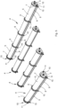
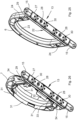
- Figure 1 illustrates a schematic perspective view of a modular filter for air intake ports decomposed into its components; the filtering fabric roll, the supporting pins within the casing, and the cover at the end of the casing open to show the time of replacement of the filtering fabric roll within the support which is usually applied to the container of the apparatus or machine on which it is employed;
- Figure 1 shows a roll 1 of filtering fabric T comprising a tubular core 2 onto which the pins 3 are inserted at each end thereof;
- the filtering fabric has a front F in length, for covering an air intake port B;
- the casing 4 has a shaped wall 5 folded into an arch with a length slightly greater than F;
- an intermediate support 6 keeps the shaped wall bent into an arch;
- two end supports 7 delimit the length of the shaped wall 5 and, like the intermediate support, hold the shaped wall at its ends;
- two stay rods 8 are arranged to tighten the two end supports and the shaped wall, bent into an arch, one to another to contain the roll 1 of filtering fabric T.
- the end supports 7, the intermediate support 6 and the shaped wall 5 have a slot 9 which is longitudinal and parallel to the front F of the filtering fabric roll 1 when mounted; an end cover 10 is placed on each end support 7 to close the casing 4 by tightening the knobs 11 at the ends of the said stay rods 8; each cover 10 has a hole 12 for housing a respective pin 3 and manually actuating it from the outside of the casing 4 when mounted.
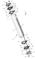
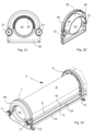
- Figures 2 to 4 show the mounted modular filter and how it is applied to the surface S of the container where the cooling air intake port B of the container itself is provided.
- the intermediate and end supports have anchoring means 13 comprising permanent magnets, housed in the base 14 of each intermediate/end support, and flaps 15 for the possible attachment with the typical screws.
- the filtering fabric T is approached, Figure 4 , to cover the intake port and is usually attached with movable permanent magnets not depicted herein.
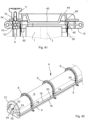
- Figure 5 shows the modularity applied to the described conformation of the modular filter according to the invention wherein the casing 4, with the shaped part 5 folded into an arch, allows to form a roll 1 for filtering fabric T with the desired length of the front F of the filtering fabric.
- the combination of the described elements, constituting each size of the casing 4 varies as a function of the length of the front F only in the length of the shaped wall 5 and of the number of intermediate supports 6, which in Figure 5 ranges from one to three, but for short embodiments may not be provided, or may be even greater for embodiments with a very long front F of the filtering fabric.
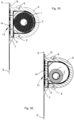
- Figures 6 to 9 show the combination of the described component parts and the mounting of the stay rods 8 on which double tightening nuts 16 are arranged, to make the mutual position of the end supports 7 stable so as to properly contain the arch-shaped wall 5; the double nuts 16 are tightened one to another on each end support 7, to fix their position on the pair of stay rods 8 which define the arch-shaped wall 5 as the main component of the casing 4 of the described modular filter.
- the possible intermediate support 6 is not fixedly positioned in the assembling performed, being able to be placed in the most convenient point for the user in mounting the modular filter for the desired application; likewise, the single intermediate support, two, three or possibly more intermediate supports 6 which are provided in the modular filter embodied as in Figure 5 are positioned as desired.
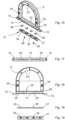
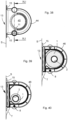
- Figures 10 to 14 show the conformation and the order of the steps of making the arch-shaped wall 5 which is embodied by a sheet 17, advantageously made of a semi-rigid plastic material, by bending two end edges 18, on the ledge 19, and end edge 20 on the bent wall 21, so as to move the end edge 20 close to the final part of the ledge 19 leaving a longitudinal slot 9 between this end edge 20 and the ledge 19 for the passage of the filtering fabric T when mounted.
- the arch-shaped wall 5 has a length L slightly greater than the length of the front F of the filtering fabric T of the roll 1; in use, the filtering fabric is extracted from the casing 4 through the slot 9 by pulling it therethrough.
- the support has a planar portion 22 and an arched portion 23, to contain the arch-shaped wall 5 and the end edges of the ledge 18 and of the bent wall 21, so as to allow the housing of the ledge 19 and the edge ends 20 to form the slot 9 when the support is mounted on the shaped wall 5 with a slot 29of the support-2-9.
- the support has holes 24 for the pass-through housing of the stay rods 8; it also has seats 25 for inserting and positioning the permanent magnets 26 in the base of the support 14 which are stopped in this base with a base cover 27 and screws 28.
- the base cover has housings 30 for the permanent magnets with snap-on projections to hold the magnet in the respective housing 30.
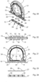
- FIGs 20 to 24 and 26 the conformation and constitution of an end support 7 and the parts embodying the anchoring means 13 are provided.
- the parts identical to the intermediate support 6 are identically numbered.
- the end support has arched lips 31 towards the two sides of the support to contain the shaped wall 5 and, on the opposite face, for coupling with the end cover 10.
- the end support has holes 34 for attaching the stay rods 8 when mounted with the nuts 16 tightened on this support on both sides of the end support 7 and for positioning it fixedly with respect to the shaped wall 5 at both ends thereof.
- Figures 28 to 30 show the conformation of the end cover 10 wherein an arched lip 35 for guiding the roll 1 and short lips 36 to be coupled with the corresponding end support 7 to close the casing 4 of the modular filter according to the invention are provided.
- On the end cover 10 holes 37 for housing the stay rods 8 and attaching this cover to the corresponding end support 7 by means of the knobs 11 screwed onto the stay rods themselves are formed.
- Figures 31 to 36 show a further constructive form wherein the end covers 40 are closed, i.e., they have a closing wall 41 of the casing 4 without the pin hole 12, that is the filtering fabric roll 1 is housed freely within the casing, as can be seen from its position in Figures 35 and 36 , when the filtering fabric roll is newly inserted, Figure 35 , and during the gradual extraction of the filtering fabric with the use of this filter, Figure 36 .
- the common parts already described are indicated with the same reference number.
- Figures 37 to 41 show a further variant of a constructive form with a single stay rod 8, wherein between the closed end covers 44, i.e. having a closing wall 45 of the casing 4 without the pin hole 12, the filtering fabric roll is housed freely within the casing, as can be seen from its position in Figures 39 and 40 , and as already shown in connection with Figures 35 and 36 .
- the common parts already described are indicated with the same reference number.
- the intermediate support 46 has a single through hole 24 and, to ensure the tightening of the single stay rod on the perimeter of the end support 47, interlocks 48 are formed on the bent wall 21 of the arch-shaped wall 5 to facilitate the insertion of a notch 49 in contact with said end support 47, so the casing 4, although tightened between the two end supports 47, is also retained on the side opposite the stay rod 8 mounted between these supports.
- Figures 42 to 45 show a further simplified constructive form of a casing 4 wherein intermediate supports 6 are positioned to wrap the arch-shaped wall 5 and to anchor the casing 4 of the filter as a whole to a wall S, as in the other constructive forms already described.
- the common parts already described are indicated with the same reference number.
- a closing cover 51 which is similar to the end covers 10 above with the end hole 12 and 44 with the closing wall 45; this closing cover has a single central hole 52 in the closed wall 53 in which a stay rod 54 which is tightened to keep the filter casing 4 closed is placed.
- the tightening of the stay rod can be carried out by a typical knob, not depicted, or by a wing nut 55 shown herein.
- the closing cover 51 lacks anchoring means and, therefore, it may be freely removed and mounted to replace the roll 1 of filtering fabric T without modifying the attachment of the casing 4 onto the wall S to which it is applied. Furthermore, the filtering fabric roll is housed freely within the casing and constrained only by the presence of the stay rod 54, as can be seen from its position in Figures 44 and 45 , and as already shown in connection with the preceding Figures.
- each intermediate or end support may be attached to the surface by means of typical screws in the flaps 15 they are provided with.
- the number of intermediate supports is proportional to the mass of the roll filtering fabric depending on the length, type and thickness of this filtering fabric T; that is, the intermediate supports, in addition to guiding the shaped wall 5, also support the mass of the filtering fabric.
- Each intermediate support 6 or 46 and end support 7 or 47, where present, is inserted in the coupling with the shaped wall 5 freely, i.e., with only the interlock or housing of the shaped wall 5, so as to make it slide over the length of the front F of the casing 4 and position the intermediate supports at the structure of the wall S on which the casing 4 with the roll filter is mounted.
- the shaped wall 5 is embodied as in Figures 11, 12 and 13 , and is bent only when it is mounted, since it is made of an adequately flexible sheet material, with the shape depicted in Figures 10 and 14 ; the intermediate and end supports keep it in an arched shape, thus forming the described casing 4.
- the shaped wall 5 may also be made of an extruded linear plastic material already with the final shape as in Figures 10 and 14 , and cut to the length L required to form the wall shaped to contain the filtering fabric roll 1 having the front F. This embodiment allows to produce an extruded profile already shaped in an arched shape, such as the one depicted in Figure 10 , which requires only the cut to the desired length L for forming a casing 4 for a filtering fabric having a specific front F.
- the constructive form with the variant of obtaining the shaped wall 5 by extrusion allows to keep in stock already shaped section bars which are only cut to the length required to satisfy the customer's needs, so as to make the production versatile and minimize costs, while achieving non-standard embodiments of the front F of the filtering fabric.
- a possible variant whether embodying the shaped wall by bending of a polycarbonate sheet or embodying it directly by extrusion, comprises the conformation of the wall having a square, a quadrilateral or a parallelogram section instead of an arched one. That is, the shaped wall depicted as arched is formed with right-angled walls and a square or parallelogram cross-section.
- the ease of replacement of the roll 1 of filtering fabric T is maximum, simply by opening at least one of the end covers 10, 40, 44, or 51 and replacing the roll core 2, now lacking filtering fabric, with a new roll 1 and keeping the end of the front F of the filtering fabric T outside the casing 4 through the slot 9 of the arch-shaped wall 5.
- the casing 4 in all the various described constructive forms, remains firmly attached by means of its intermediate or end supports to the structure of the wall S to which it is attached.
- the shaped wall may be formed without a ledge, i.e., with a completely arched, or even square or parallelogram, conformation, and provided with the end edges to define the passage slot for the filtering fabric.
- the coupling between the end support 47 of the casing 4 can be formed without the notches 49 and the respective interlocks 48 at the end 50 of the shaped wall 5.
- the pins 3 may be used with a respective cover 10, provided with a pin hole 12 also in the constructive forms of Figures 33-34 and 37 for replacing the covers with a closing wall.
Landscapes
- Chemical & Material Sciences (AREA)
- Chemical Kinetics & Catalysis (AREA)
- Filtering Of Dispersed Particles In Gases (AREA)
- Cooling Or The Like Of Electrical Apparatus (AREA)
- Filtering Materials (AREA)
- Casings For Electric Apparatus (AREA)
Claims (15)
- Modularer Filter für Lüftungsöffnungen mit einer Filtertuchrolle (1), die in einem Gehäuse untergebracht ist, das mit Verankerungsmitteln (13) versehen ist, die in die Oberfläche (S) des Behälters eingreifen, der den zu filternden Lufteintrittsanschluss (B) aufweist; das Gehäuse weist einen Schlitz (9) zur Entnahme des Filtertuchs (T) auf; dadurch gekennzeichnet, dass er ein Gehäuse (4) aufweist, das aus einer geformten Wand (5) besteht, die an den Enden von Abdeckungen (10, 40, 44, 51) oder Endstützen (7, 47) dieser Wand umschlossen ist, die eine der geformten Wand (5) entsprechende Form aufweisen und an den vorderen Rändern der geformten Wand einen Längsschlitz (9) beibehalten, um den Durchgang für die Entnahme der Vorderseite (F) des von der Filtertuchrolle (1) abgewickelten Filtertuchs (T) zu ermöglichen; mindestens eine Schraubenhaltestange (8, 54) ist zwischen zwei Abdeckungen (51) oder Endstützen (7, 47) der geformten Wand angeordnet und ist festgezogen, um den richtigen Abstand zwischen den beiden Endstützen oder Abdeckungen (51) zu definieren, indem die Endstützen (7, 47) oder Abdeckungen (51) an der geformten Wand (5) festgezogen werden, eine an jedem Ende, um den Zugang zu dem Gehäuse zu verschließen und die Filtertuchrolle (1) schwimmend und frei drehbar zu halten, wenn das Filtertuch von der Außenseite des modularen Filters gezogen wird.
- Modularer Filter nach Anspruch 1, wobei die Haltestange durch mindestens ein Paar mit Gewinde versehene Haltestangen (8) ersetzt ist und die Filtertuchrolle (1) in dem Gehäuse (4) enthalten ist, das aus der geformten Wand (5) und den beiden Abdeckungen (10, 40) oder den beiden Endstützen (7, 47) dieser Wand besteht.
- Modularer Filter nach Anspruch 1 oder 2, wobei die geformte Wand (5) bogenförmig ausgebildet ist, um den Außendurchmesser der Filtertuchrolle (1) zu umfassen.
- Modularer Filter nach einem der Ansprüche 1, 2 oder 3, wobei mindestens eine Zwischenstütze (6) dieser geformten Wand (5), die zwischen den beiden Endstützen (7, 47) angeordnet ist, zur Aufnahme des Gehäuses (4) vorgesehen ist.
- Modularer Filter nach einem der Ansprüche 1 oder 3, wobei mindestens ein Paar Zwischenstützen (6) dieser geformten Wand (5) vorgesehen ist, die auf den Zwischenstützen (6) untergebracht und durch zwei Abdeckungen (51) verschlossen sind, mit einer zentralen Haltestange (54), die in der Verschlusswand (53) der Abdeckungen angeordnet ist, um das Gehäuses (4) zu verschließen.
- Modularer Filter nach einem der Ansprüche 1, 2, 3 oder 4, wobei mindestens eine Endstütze mit einer Endabdeckung (10, 40, 44) verbunden ist, die getrennt von der Endstütze (7, 47) an einem entsprechenden Ende des Gehäuses (4) entfernt werden kann, um auf die Rolle (1) des Filtertuchs (T) zuzugreifen und sie zu ersetzen.
- Modularer Filter nach einem der Ansprüche 1, 2 oder 3, wobei die geformte Wand (5) als eine Platte aus einem Kunststoffmaterial ausgebildet ist, die vorab entlang ihrer Länge (L) gebogen ist, mit einer Leiste (19), die mit einer Endkante (18) der Leiste versehen ist, und einer Wand (21), wobei die Endkante der Wand (20) während der Montage elastisch gebogen wird, um die für das Einsetzen in die Endstützen erforderliche Form anzunehmen, wobei die gebogene Form entweder die gewölbte (5) oder sogar die quadratische oder parallelogrammförmige sein kann.
- Der modulare Filter nach einem der vorhergehenden Ansprüche, wobei die geformte Wand (5) durch Biegen einer Platte aus Polycarbonat gebildet ist.
- Modularer Filter nach einem der vorhergehenden Ansprüche 1 bis 7, wobei die geformte Wand (5) durch Extrudieren von Polycarbonat geformt ist, um die beabsichtigte Form des Gehäuses zu erhalten.
- Modularer Filter nach einem der Ansprüche 1 bis 4 oder 6, wobei die Endabdeckungen (40, 44) eine Verschlusswand (41, 45) aufweisen.
- Modularer Filter nach einem der Ansprüche 1 bis 4 oder 6, wobei eine einzelne Haltestange (8), die an der Seite des Längsschlitzes (9) angeordnet ist, zum Festziehen der Endstützen (47) vorgesehen ist.
- Modularer Filter nach Anspruch 11, wobei eine einzelne Haltestange (8) vorgesehen ist, um die Endstützen (47) festzuziehen, und Verriegelungen (48) und entsprechende Kerben (49) auch in der Verbindung der Endstützen und dem Ende (50) der geformten Wand (5) ausgebildet sind.
- Modularer Filter nach Anspruch 5, bei dem eine Flügelmutter (55) an den Enden der Haltestange (54) eingesetzt ist, um das Anbringen oder Abnehmen der Verschlussabdeckung(en) (51) zu ermöglichen, die an den Enden des Gehäuses (4) vorgesehen sind.
- Modularer Filter nach einem der vorhergehenden Ansprüche 1 bis 4 und 6 bis 12, wobei die Filtertuchrolle (1) mindestens einen Stift (3) aufweist, der in einen Kern (2) der Rolle eingesetzt ist und aus der jeweiligen Endabdeckung (10) herausragt, um das Aufwickeln der Filtertuchrolle (T) selbst manuell zu tätigen.
- Modularer Filter nach einem der vorhergehenden Ansprüche, wobei mindestens ein Knopf (11) am Ende der Haltestange (8) eingesetzt ist, um das Anbringen oder Abnehmen der am Ende des Gehäuses (4) vorgesehenen Endstütze und/oder Abdeckung zu ermöglichen.
Applications Claiming Priority (2)
| Application Number | Priority Date | Filing Date | Title |
|---|---|---|---|
| IT102018000010016A IT201800010016A1 (it) | 2018-11-02 | 2018-11-02 | Filtro modulare per bocche d'aria di ventilazione |
| PCT/IT2019/050234 WO2020089955A1 (en) | 2018-11-02 | 2019-11-02 | Modular filter for ventilation air vents |
Publications (3)
| Publication Number | Publication Date |
|---|---|
| EP3873643A1 EP3873643A1 (de) | 2021-09-08 |
| EP3873643B1 true EP3873643B1 (de) | 2024-01-03 |
| EP3873643C0 EP3873643C0 (de) | 2024-01-03 |
Family
ID=65496816
Family Applications (1)
| Application Number | Title | Priority Date | Filing Date |
|---|---|---|---|
| EP19817427.8A Active EP3873643B1 (de) | 2018-11-02 | 2019-11-02 | Modularer filter für lüftungsöffnungen |
Country Status (7)
| Country | Link |
|---|---|
| US (1) | US12053732B2 (de) |
| EP (1) | EP3873643B1 (de) |
| JP (1) | JP7549890B2 (de) |
| CA (1) | CA3118487A1 (de) |
| ES (1) | ES2973077T3 (de) |
| IT (1) | IT201800010016A1 (de) |
| WO (1) | WO2020089955A1 (de) |
Families Citing this family (5)
| Publication number | Priority date | Publication date | Assignee | Title |
|---|---|---|---|---|
| KR102630760B1 (ko) * | 2020-07-03 | 2024-01-26 | 에스케이넥실리스 주식회사 | 동박용 수납장치 |
| CN113899044B (zh) * | 2021-11-18 | 2023-01-10 | 山东蓝诺机械制造有限公司 | 一种低噪声的被动式隔声窗用通风器 |
| US12371833B2 (en) * | 2022-08-31 | 2025-07-29 | Gracewood Management, Inc. | Fabric retention clip and rail |
| KR102742627B1 (ko) * | 2022-10-26 | 2024-12-16 | 주식회사 테리어스 | 롤스크린식 렌지후드용 보조필터장치 |
| CN117167884B (zh) * | 2023-10-08 | 2024-07-30 | 福建省万禾节能科技有限公司 | 一种车间用空气处理装置及方法 |
Citations (1)
| Publication number | Priority date | Publication date | Assignee | Title |
|---|---|---|---|---|
| GB1229095A (de) * | 1968-10-12 | 1971-04-21 |
Family Cites Families (13)
| Publication number | Priority date | Publication date | Assignee | Title |
|---|---|---|---|---|
| JPS4617264Y1 (de) * | 1968-06-26 | 1971-06-16 | ||
| US4627863A (en) * | 1985-07-31 | 1986-12-09 | Max Klein | Filter for air handling equipment |
| JPH01228520A (ja) * | 1988-03-09 | 1989-09-12 | Nippon Denso Co Ltd | 空気清浄装置 |
| US5529593A (en) * | 1994-10-07 | 1996-06-25 | Air Solution Company | Filter screen assembly for use with an air intake unit |
| JPH1133325A (ja) * | 1997-07-23 | 1999-02-09 | Norihito Sako | 排気浄化装置 |
| JP3508721B2 (ja) * | 2000-12-22 | 2004-03-22 | ダイキン工業株式会社 | フィルタ |
| JP2005207717A (ja) * | 2004-01-22 | 2005-08-04 | Hiroshi Kashiwagi | 換気扇ロールフィルター |
| US8172406B2 (en) * | 2007-01-26 | 2012-05-08 | Panasonic Corporation | Powder dust capture device and projection type image display device |
| US20100077923A1 (en) * | 2008-09-30 | 2010-04-01 | Travis Lewis | Filter apparatus and method |
| US9375669B2 (en) * | 2013-06-19 | 2016-06-28 | Bill Spiegel | Air filtration apparatus |
| JP3186179U (ja) * | 2013-07-10 | 2013-09-19 | 株式会社橋本クロス | 防塵フィルター |
| JP6924258B2 (ja) * | 2017-03-27 | 2021-08-25 | シャープ株式会社 | 空気清浄機 |
| CN211635716U (zh) * | 2019-09-04 | 2020-10-09 | 陈镇海 | 过滤装置和空调 |
-
2018
- 2018-11-02 IT IT102018000010016A patent/IT201800010016A1/it unknown
-
2019
- 2019-11-02 WO PCT/IT2019/050234 patent/WO2020089955A1/en not_active Ceased
- 2019-11-02 EP EP19817427.8A patent/EP3873643B1/de active Active
- 2019-11-02 JP JP2021523784A patent/JP7549890B2/ja active Active
- 2019-11-02 CA CA3118487A patent/CA3118487A1/en active Pending
- 2019-11-02 US US17/289,099 patent/US12053732B2/en active Active
- 2019-11-02 ES ES19817427T patent/ES2973077T3/es active Active
Patent Citations (1)
| Publication number | Priority date | Publication date | Assignee | Title |
|---|---|---|---|---|
| GB1229095A (de) * | 1968-10-12 | 1971-04-21 |
Also Published As
| Publication number | Publication date |
|---|---|
| IT201800010016A1 (it) | 2020-05-02 |
| ES2973077T3 (es) | 2024-06-18 |
| JP7549890B2 (ja) | 2024-09-12 |
| EP3873643A1 (de) | 2021-09-08 |
| WO2020089955A1 (en) | 2020-05-07 |
| US20220008857A1 (en) | 2022-01-13 |
| EP3873643C0 (de) | 2024-01-03 |
| JP2022506419A (ja) | 2022-01-17 |
| US12053732B2 (en) | 2024-08-06 |
| CA3118487A1 (en) | 2020-05-07 |
Similar Documents
| Publication | Publication Date | Title |
|---|---|---|
| EP3873643B1 (de) | Modularer filter für lüftungsöffnungen | |
| US4078741A (en) | Textile spool | |
| EP3130742B1 (de) | Schirmbildende vorrichtung | |
| DE102011077989B4 (de) | Kombination aus einem Toilettenpapierspender und einem Fluidspender | |
| WO2014022007A1 (en) | Center spreader adapter tool for toilet paper rolls and paper towel rolls that do not have inner cardboard tubes | |
| US5957324A (en) | Towel dispencer adapter | |
| KR101868994B1 (ko) | 테이프의 커팅 길이 조절이 가능한 디스펜서 | |
| DE69515805T2 (de) | Kabelaufrollvorrichtung eines Staubsaugers | |
| US20230018336A1 (en) | Air filter for air conditioning system | |
| DE2660995C2 (de) | Kassette für automatische Kopiergeräte | |
| CN107651475B (zh) | 一种吸附辊以及对薄片状产品进行加工的设备 | |
| CN110626852B (zh) | 一种修正带芯加工成型装置 | |
| KR101644504B1 (ko) | 덕트 공기 정화용 필터 장치 | |
| DE69100474T2 (de) | Filtergerät und druckstabilisierer für lüftungsanlagen mit variablem durchfluss. | |
| EP0300357A1 (de) | Vorrichtung für die Aufbewahrung von auf Rollen aufgewickeltem Papier | |
| KR200430389Y1 (ko) | 롤 블라인드의 채널바아 | |
| DE202017106024U1 (de) | Aufkleberaufwickelvorrichtung | |
| CN220739139U (zh) | 一种警示灯背板加强筋成型设备 | |
| CN213300322U (zh) | 一种可更换滤网的除湿机 | |
| DE1607661B2 (de) | Gas- oder luftfilter | |
| CN222331148U (zh) | 下切刀机构及分切机 | |
| CN111331672A (zh) | 一种具有打孔校准辅助装置的塑料防护膜打孔机 | |
| TWI284102B (en) | A film base of a cap sealing machine | |
| CN112378021B (zh) | 能自由调节的空气净化排放机构 | |
| CN212891312U (zh) | 一种分段计数包装机 |
Legal Events
| Date | Code | Title | Description |
|---|---|---|---|
| STAA | Information on the status of an ep patent application or granted ep patent |
Free format text: STATUS: UNKNOWN |
|
| STAA | Information on the status of an ep patent application or granted ep patent |
Free format text: STATUS: THE INTERNATIONAL PUBLICATION HAS BEEN MADE |
|
| PUAI | Public reference made under article 153(3) epc to a published international application that has entered the european phase |
Free format text: ORIGINAL CODE: 0009012 |
|
| STAA | Information on the status of an ep patent application or granted ep patent |
Free format text: STATUS: REQUEST FOR EXAMINATION WAS MADE |
|
| 17P | Request for examination filed |
Effective date: 20210531 |
|
| AK | Designated contracting states |
Kind code of ref document: A1 Designated state(s): AL AT BE BG CH CY CZ DE DK EE ES FI FR GB GR HR HU IE IS IT LI LT LU LV MC MK MT NL NO PL PT RO RS SE SI SK SM TR |
|
| DAV | Request for validation of the european patent (deleted) | ||
| DAX | Request for extension of the european patent (deleted) | ||
| STAA | Information on the status of an ep patent application or granted ep patent |
Free format text: STATUS: EXAMINATION IS IN PROGRESS |
|
| 17Q | First examination report despatched |
Effective date: 20220523 |
|
| GRAP | Despatch of communication of intention to grant a patent |
Free format text: ORIGINAL CODE: EPIDOSNIGR1 |
|
| STAA | Information on the status of an ep patent application or granted ep patent |
Free format text: STATUS: GRANT OF PATENT IS INTENDED |
|
| INTG | Intention to grant announced |
Effective date: 20230530 |
|
| GRAS | Grant fee paid |
Free format text: ORIGINAL CODE: EPIDOSNIGR3 |
|
| GRAA | (expected) grant |
Free format text: ORIGINAL CODE: 0009210 |
|
| STAA | Information on the status of an ep patent application or granted ep patent |
Free format text: STATUS: THE PATENT HAS BEEN GRANTED |
|
| AK | Designated contracting states |
Kind code of ref document: B1 Designated state(s): AL AT BE BG CH CY CZ DE DK EE ES FI FR GB GR HR HU IE IS IT LI LT LU LV MC MK MT NL NO PL PT RO RS SE SI SK SM TR |
|
| REG | Reference to a national code |
Ref country code: GB Ref legal event code: FG4D |
|
| REG | Reference to a national code |
Ref country code: CH Ref legal event code: EP |
|
| REG | Reference to a national code |
Ref country code: DE Ref legal event code: R096 Ref document number: 602019044572 Country of ref document: DE |
|
| REG | Reference to a national code |
Ref country code: IE Ref legal event code: FG4D |
|
| U01 | Request for unitary effect filed |
Effective date: 20240111 |
|
| U07 | Unitary effect registered |
Designated state(s): AT BE BG DE DK EE FI FR IT LT LU LV MT NL PT SE SI Effective date: 20240119 |
|
| REG | Reference to a national code |
Ref country code: ES Ref legal event code: FG2A Ref document number: 2973077 Country of ref document: ES Kind code of ref document: T3 Effective date: 20240618 |
|
| PG25 | Lapsed in a contracting state [announced via postgrant information from national office to epo] |
Ref country code: IS Free format text: LAPSE BECAUSE OF FAILURE TO SUBMIT A TRANSLATION OF THE DESCRIPTION OR TO PAY THE FEE WITHIN THE PRESCRIBED TIME-LIMIT Effective date: 20240503 |
|
| PG25 | Lapsed in a contracting state [announced via postgrant information from national office to epo] |
Ref country code: GR Free format text: LAPSE BECAUSE OF FAILURE TO SUBMIT A TRANSLATION OF THE DESCRIPTION OR TO PAY THE FEE WITHIN THE PRESCRIBED TIME-LIMIT Effective date: 20240404 |
|
| PG25 | Lapsed in a contracting state [announced via postgrant information from national office to epo] |
Ref country code: HR Free format text: LAPSE BECAUSE OF FAILURE TO SUBMIT A TRANSLATION OF THE DESCRIPTION OR TO PAY THE FEE WITHIN THE PRESCRIBED TIME-LIMIT Effective date: 20240103 Ref country code: RS Free format text: LAPSE BECAUSE OF FAILURE TO SUBMIT A TRANSLATION OF THE DESCRIPTION OR TO PAY THE FEE WITHIN THE PRESCRIBED TIME-LIMIT Effective date: 20240403 |
|
| PG25 | Lapsed in a contracting state [announced via postgrant information from national office to epo] |
Ref country code: CZ Free format text: LAPSE BECAUSE OF FAILURE TO SUBMIT A TRANSLATION OF THE DESCRIPTION OR TO PAY THE FEE WITHIN THE PRESCRIBED TIME-LIMIT Effective date: 20240103 |
|
| PG25 | Lapsed in a contracting state [announced via postgrant information from national office to epo] |
Ref country code: RS Free format text: LAPSE BECAUSE OF FAILURE TO SUBMIT A TRANSLATION OF THE DESCRIPTION OR TO PAY THE FEE WITHIN THE PRESCRIBED TIME-LIMIT Effective date: 20240403 Ref country code: NO Free format text: LAPSE BECAUSE OF FAILURE TO SUBMIT A TRANSLATION OF THE DESCRIPTION OR TO PAY THE FEE WITHIN THE PRESCRIBED TIME-LIMIT Effective date: 20240403 Ref country code: IS Free format text: LAPSE BECAUSE OF FAILURE TO SUBMIT A TRANSLATION OF THE DESCRIPTION OR TO PAY THE FEE WITHIN THE PRESCRIBED TIME-LIMIT Effective date: 20240503 Ref country code: HR Free format text: LAPSE BECAUSE OF FAILURE TO SUBMIT A TRANSLATION OF THE DESCRIPTION OR TO PAY THE FEE WITHIN THE PRESCRIBED TIME-LIMIT Effective date: 20240103 Ref country code: GR Free format text: LAPSE BECAUSE OF FAILURE TO SUBMIT A TRANSLATION OF THE DESCRIPTION OR TO PAY THE FEE WITHIN THE PRESCRIBED TIME-LIMIT Effective date: 20240404 Ref country code: CZ Free format text: LAPSE BECAUSE OF FAILURE TO SUBMIT A TRANSLATION OF THE DESCRIPTION OR TO PAY THE FEE WITHIN THE PRESCRIBED TIME-LIMIT Effective date: 20240103 |
|
| PG25 | Lapsed in a contracting state [announced via postgrant information from national office to epo] |
Ref country code: PL Free format text: LAPSE BECAUSE OF FAILURE TO SUBMIT A TRANSLATION OF THE DESCRIPTION OR TO PAY THE FEE WITHIN THE PRESCRIBED TIME-LIMIT Effective date: 20240103 |
|
| PG25 | Lapsed in a contracting state [announced via postgrant information from national office to epo] |
Ref country code: PL Free format text: LAPSE BECAUSE OF FAILURE TO SUBMIT A TRANSLATION OF THE DESCRIPTION OR TO PAY THE FEE WITHIN THE PRESCRIBED TIME-LIMIT Effective date: 20240103 |
|
| REG | Reference to a national code |
Ref country code: DE Ref legal event code: R097 Ref document number: 602019044572 Country of ref document: DE |
|
| PG25 | Lapsed in a contracting state [announced via postgrant information from national office to epo] |
Ref country code: SM Free format text: LAPSE BECAUSE OF FAILURE TO SUBMIT A TRANSLATION OF THE DESCRIPTION OR TO PAY THE FEE WITHIN THE PRESCRIBED TIME-LIMIT Effective date: 20240103 |
|
| PG25 | Lapsed in a contracting state [announced via postgrant information from national office to epo] |
Ref country code: SK Free format text: LAPSE BECAUSE OF FAILURE TO SUBMIT A TRANSLATION OF THE DESCRIPTION OR TO PAY THE FEE WITHIN THE PRESCRIBED TIME-LIMIT Effective date: 20240103 |
|
| PG25 | Lapsed in a contracting state [announced via postgrant information from national office to epo] |
Ref country code: SM Free format text: LAPSE BECAUSE OF FAILURE TO SUBMIT A TRANSLATION OF THE DESCRIPTION OR TO PAY THE FEE WITHIN THE PRESCRIBED TIME-LIMIT Effective date: 20240103 Ref country code: SK Free format text: LAPSE BECAUSE OF FAILURE TO SUBMIT A TRANSLATION OF THE DESCRIPTION OR TO PAY THE FEE WITHIN THE PRESCRIBED TIME-LIMIT Effective date: 20240103 Ref country code: RO Free format text: LAPSE BECAUSE OF FAILURE TO SUBMIT A TRANSLATION OF THE DESCRIPTION OR TO PAY THE FEE WITHIN THE PRESCRIBED TIME-LIMIT Effective date: 20240103 |
|
| PLBE | No opposition filed within time limit |
Free format text: ORIGINAL CODE: 0009261 |
|
| STAA | Information on the status of an ep patent application or granted ep patent |
Free format text: STATUS: NO OPPOSITION FILED WITHIN TIME LIMIT |
|
| 26N | No opposition filed |
Effective date: 20241007 |
|
| U20 | Renewal fee for the european patent with unitary effect paid |
Year of fee payment: 6 Effective date: 20241127 |
|
| PGFP | Annual fee paid to national office [announced via postgrant information from national office to epo] |
Ref country code: GB Payment date: 20241127 Year of fee payment: 6 |
|
| PGFP | Annual fee paid to national office [announced via postgrant information from national office to epo] |
Ref country code: ES Payment date: 20241202 Year of fee payment: 6 |
|
| REG | Reference to a national code |
Ref country code: CH Ref legal event code: PL |
|
| PG25 | Lapsed in a contracting state [announced via postgrant information from national office to epo] |
Ref country code: MC Free format text: LAPSE BECAUSE OF FAILURE TO SUBMIT A TRANSLATION OF THE DESCRIPTION OR TO PAY THE FEE WITHIN THE PRESCRIBED TIME-LIMIT Effective date: 20240103 |
|
| REG | Reference to a national code |
Ref country code: CH Ref legal event code: PL |
|
| PG25 | Lapsed in a contracting state [announced via postgrant information from national office to epo] |
Ref country code: CH Free format text: LAPSE BECAUSE OF NON-PAYMENT OF DUE FEES Effective date: 20241130 |
|
| PG25 | Lapsed in a contracting state [announced via postgrant information from national office to epo] |
Ref country code: IE Free format text: LAPSE BECAUSE OF NON-PAYMENT OF DUE FEES Effective date: 20241102 |