EP3873593B1 - Inductive applicator coil arrangement for therapeutically treating human and animal bodies - Google Patents
Inductive applicator coil arrangement for therapeutically treating human and animal bodies Download PDFInfo
- Publication number
- EP3873593B1 EP3873593B1 EP19872967.5A EP19872967A EP3873593B1 EP 3873593 B1 EP3873593 B1 EP 3873593B1 EP 19872967 A EP19872967 A EP 19872967A EP 3873593 B1 EP3873593 B1 EP 3873593B1
- Authority
- EP
- European Patent Office
- Prior art keywords
- active
- electrically
- coils
- conductive loops
- loops
- Prior art date
- Legal status (The legal status is an assumption and is not a legal conclusion. Google has not performed a legal analysis and makes no representation as to the accuracy of the status listed.)
- Active
Links
Images





Classifications
-
- A—HUMAN NECESSITIES
- A61—MEDICAL OR VETERINARY SCIENCE; HYGIENE
- A61N—ELECTROTHERAPY; MAGNETOTHERAPY; RADIATION THERAPY; ULTRASOUND THERAPY
- A61N2/00—Magnetotherapy
- A61N2/02—Magnetotherapy using magnetic fields produced by coils, including single turn loops or electromagnets
-
- A—HUMAN NECESSITIES
- A61—MEDICAL OR VETERINARY SCIENCE; HYGIENE
- A61N—ELECTROTHERAPY; MAGNETOTHERAPY; RADIATION THERAPY; ULTRASOUND THERAPY
- A61N1/00—Electrotherapy; Circuits therefor
- A61N1/40—Applying electric fields by inductive or capacitive coupling ; Applying radio-frequency signals
Definitions
- the invention relates to an apparatus for efficient distribution of pulsed electromagnetic waveforms for targeted pulsed electromagnetic field (PEMF) treatment of living humans and animals, tissues and cells utilizing a combination of active and non-active coils.
- PEMF pulsed electromagnetic field
- the invention relates also to a corresponding in vitro or ex vivo method for treating a cell, tissue or organ.
- This apparatus and method relates to the more efficient treatment of living humans, animals, tissues, cells and/or organs by altering their interaction with their electromagnetic environment.
- the disclosure also relates to a method of modification of cellular and tissue growth, repair, maintenance, and general behavior by the application of encoded electromagnetic information. More particularly, this disclosure provides a device for the application, by surgically non-invasive reactive coupling, of highly specific electromagnetic signal patterns to one or more body parts through an arrangement of active coils inductively coupled to non-active coils upon or within a surface where a human or animal would lie upon or coupled within a garment, bandage or other carrier to apply the output of the inductive coil arrangement to a body, area or part.
- the present disclosure relates to the use of lightweight flexible active coils that are energized with specific electromagnetic waveforms which may be placed within a mattress, pad, cushioned or non-cushioned substrate to provide application of the therapeutic output while the human or animal is lying thereupon or while a pad, mat, blanket, or the like, incorporating the coils is placed on the human or animal subject.
- the inductive coil arrangement can be placed in an appropriate garment, bandage or dressing to deliver the optimum dose of non-invasive pulsed electromagnetic treatment for enhanced repair and growth of living tissue in humans and animals.
- the disclosed method more particularly includes the provision of a flux path, to an entire human or animal body by incorporating one or more inductive coil arrangements within a surface upon which an animal or human may lie upon during treatment.
- One or more inductive coil arrangements can be applied to provide a flux path to a selectable body region, of a succession of EMF pulses having a minimum width characteristic of at least 0.01 microseconds in a pulse burst envelope having between 100 and 10,000 pulses per burst, in which a voltage amplitude envelope of said pulse burst is defined by a randomly varying parameter in which the instantaneous minimum amplitude thereof is not smaller than the maximum amplitude thereof by a factor of one ten thousandth. Further, the repetition rate of such pulse bursts may vary from 0.01 to 1,000 Hertz. In special cases a mathematically definable parameter may be employed in lieu of said random amplitude envelope of the pulse bursts.
- an object of the invention to provide an improved apparatus for the beneficial treatment of living human and animal bodies, cells, tissue and organs by proscribing an area circumscribed by the combination of active and non-active coils arranged within a mattress, pad, cushioned or non-cushioned surface upon which an animal or human would lie upon thereby allowing for treatment of the entire body or parts thereof while the human or animal is lying upon such surface.
- the combination and arrangement of active and non-active coils allows for the treatment of larger areas by situating an active coil to be inductively coupling with one or more non-active coils thereby disbursing the energy from the active coil across the areas of the adjacent non-active coils.
- the active coil is powered by an electronic generator that produces the desired EMF signal and applies it to the active coil.
- non-active coils duplicate the output signal from the active coil to act simultaneously as a receiver and transmitter without requiring electrical power by such non-active coils being inductively coupled to the active coils with a tuned circuit adjusted to the active coil output parameters.
- Velcro ® hook and loop
- An inductive applicator coil arrangement apparatus and method which allows broad spectral density bursts of electromagnetic waveforms to be applied to an active coil placed within proximity of one or more non-active coils.
- the non-active coils are configured to be inductively coupled to, and energized by, the active coil thereby dispersing the therapeutic output across the larger area circumscribed by the combination of active and non-active coils, to be selectively applied to a living human or animal body (or to living cells, tissues and organs) for therapeutic purposes.
- the active coil electromagnetic waveform output has a frequency in the range of one (1) to one hundred (100) megahertz, with one (1) to one hundred thousand (100,000) pulses per burst, and with a burst-repetition rate of one hundredth (0.01) to one thousand (1,000) Hertz.
- the inductive applicator coil arrangement can be placed within a mattress, pad, cushioned or non-cushioned substrate to provide application of the therapeutic output while the human or animal is lying thereupon.
- one or more inductive applicator coil arrangements can be placed adjacent to the tissue target by incorporating within a garment, bandage or support fabricated with compartments or sections to house the coils at appropriate anatomical locations.
- the inductive applicator coil arrangement may also form an integral portion of a garment designed for daily, exercise or sports use through the use of conductive thread or fine, flexible wire.
- the garment may be for exercise, sports, physical rehabilitation or as a post-surgical, non-invasive, non-pharmacological anti-inflammatory therapeutic modality.
- the inductive applicator coil arrangement may be incorporated into or be an integral part of various types of bandages, including, but not limited to, compression, elastic, cold or hot compress, etc.
- the waveforms applied by the active and non-active coils of the present invention were configured for maximum efficiency allowing the complete electromagnetic treatment system to be lightweight, battery operated and portable.
- the waveforms are designed to modulate living cell growth and repair.
- Particular applications of the present invention include, but are not limited to, angiogenesis, improved micro-vascular blood perfusion, vasodilation, reduced transudation, stimulation of neovascularization bone repair, wound repair, pain relief, edema reduction, increased blood flow and to provide anti-inflammatory effects.
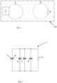
- FIG. 1 is a diagram of a treatment apparatus coil array having an active coil and a non-active coil according to an exemplary embodiment of the invention.
- a treatment apparatus coil array 100 may comprise at least one wire loop 1 forming a coil, a signal generator 2 which is powered by an electrical power supply for generating a PEMF signal to be transmitted via the coil (hereinafter also referred to as wire loop) 1 and, thereby, providing a treatment signal directed towards a human or animal subject by placing the coil 1 proximate a treatment target of the subject.
- Signal generator 2 may comprise drive circuitry coupled to a power source, such as a battery, a household A/C power source via a power converter, and the like.
- array 100 may further comprise one or more additional coils (or wire loops), for example, coil 3 that is coupled to a tuned passive circuit 4.
- Circuit 4 is configured to be induced by the signal generator 2 via coils 1 and 3 to, thereby, provide a treatment signal proximate loop 3 without requiring a separate electrical power connection.
- Loop 3 and circuit 4 function together to output a signal based on the signal output from loop 1 and signal generator 2.
- circuit 3 may be tuned according to the signal from loop 1 and signal generator 2 so that a treatment signal output from loop 3 is an approximate duplicate of the treatment signal output from loop 1. Consequently, an approximately uniform treatment signal field may be generated across loops 1 and 2.
- each coil 1 and 3 may be approximately 3 to 15 inches in diameter (e.g., AC powered apparatus), and may preferably be between 3.5 to 8.5 inches in diameter (e.g., battery powered apparatus). For example, each coil 1 and 3 may be approximately 7 inches in diameter.
- An optimal power output of coils 1 and 3 may be in the range of 100-300 mV (millivolts), or 110-250 mV, and is preferably an average peak-to-peak amplitude of at least 130 mV.
- Coils 1 and 3 forming array 100 may be mounted to a substrate, such as incorporated within a cushioned sleeve between two cushion layers that are made from, for example, foam rubber and the like.
- the coils may be embedded within a soft polymer enclosure to one side of a cushion layer.
- the treatment surface for such a treatment pad/bed may be on the polymer enclosure side or the cushion layer side.
- each of the coils 1 and 3 may be sized and shaped differently to accommodate differently sized arrays, pads, beds, enclosures, garments, carriers, patients, and corresponding treatment depth.
- a treatment pad/bed incorporating array 100 may be disposed within, for example, a pet carrier for treating small pet animals while transporting the treatment subject.
- FIG. 2 is a schematic diagram of tunable circuit 4 for coupling to the non-active coil 3 of FIG. 1 according to an exemplary embodiment of the invention.
- circuit 4 may comprise one or more capacitors--for example, three (3) as illustrated in FIG. 2 -- connected in parallel with one or more resistors--for example, one (1) as illustrated in FIG. 2 .
- circuit 4 comprises an additional variable capacitor 5 connected in parallel to the one or more (e.g., three) capacitors 6, 7, and 8, and (e.g., one) resistors 9.
- variable capacitor 5 may be a trimmer/variable capacitor with a 6.5 - 30 pF range at 100 V (N120), the resistor 9 may be a 15K Ohm 1% 1/10W (0603) resistor, and the one or more capacitors 6, 7, and 8 may comprise a ceramic capacitor with 27 pF at 100 V (C0G/NP0 0603) and another ceramic capacitor with 10 pF at 100V (C0G/NP0 0603).
- the one or more capacitors 6, 7, and 8 may be replaced with different capacitances so that the total capacitance of circuit 4 may be adjusted according to the sizes of coils 1 and 3.
- FIG. 3 is an image of non-active coil assembly 300 formed by coil 3 and circuit 4 according to an exemplary embodiment of the invention.
- assembly 300 may comprise coil 3 that is formed in a shape that is not strictly circular-such as, for example, oval or racetrack-shaped--in order to accommodate various kinds of arrays, pads, beds, enclosures, carriers, patients, and corresponding treatment depth.
- FIG. 4 is an image of circuit 4 connected to coil 3 and illustrating variable capacitor 400 for convenient tuning of circuit 4.
- circuit 4 may be disposed within an enclosure after tuning of variable capacitor 400 is completed.
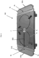
- FIG. 5 is an image of an array 500 having coils 1a, 1b, 3a, and 3b corresponding to coils 1 and 3, respectively, illustrated in FIG. 1 and described above.
- coils 1a and 1b may both be connected to a same signal generator 2, which is powered by a power source through a wire 505 to a power source connector 510.
- different numbers of coils corresponding to coils 1a and 1b may be connected to respective signal generators--for example, coils may each be connected to a separate signal generator or plural coils having approximately the same size and shape may be connected together to a single signal generator.
- FIG. 5 is an image of an array 500 having coils 1a, 1b, 3a, and 3b corresponding to coils 1 and 3, respectively, illustrated in FIG. 1 and described above.
- coils 1a and 1b may both be connected to a same signal generator 2, which is powered by a power source through a wire 505 to a power source connector 510.
- coils 3a and 3b may each form non-active coil assemblies 300a and 300b with respective non-active circuits 4a and 4b in correspondence with assembly 300 illustrated in FIG. 3 and described above.
- a different number of non-active coils that are similar or different in shape and size to coils 3a and 3b may be placed in proximity of coils 1a and 1b to form array 500.
- coils 1a and 1b have a one-to-one relationship with non-active coils 3a and 3b.
- coils 3a and 3b may approximate a "D" shape and may have a similar circumferential length as coils 1a and 1b, which have a diameter of approximately 7 inches.
- coils 1a, 1b, 3a, and 3b may have aligned centers along an axis where coil 1a and 3a (1b and 3b) are approximately 0.5 inches apart at the closest point--i.e., from the outer circumference of coil 1a/1b to circuit 4a/4b shown in FIG. 5 .
- array 500 may be place in a test fixture, such as the APB-FX001 Test Fixture shown in FIG. 5 .
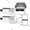
- FIG. 6 is a diagram showing a testing assembly 600 for the treatment apparatus coil array 500 of FIG. 5 in accordance with an exemplary embodiment of the invention.
- an oscilloscope e.g., Tektronix ® TDS 2012B or equivalent
- respective RF probes attached thereto may be used to measure the treatment signal outputs of the respective coils 1a, 1b, 3a, and 3b of array 500.
- the probes were placed at the center of the respective coils 1a, 1b, 3a, and 3b at a height of approximately 1 cm from a plane of the coils.
- testing assembly may comprise a mini controller for controlling and adjusting the output of signal generator 2.
- signal generator 2 may be integrated with a controller that provides control and output functionality that corresponds to the mini controller shown in FIG. 6 for, as an example, programming array 500 in a treatment apparatus using an onboard or wireless user interface, and the like.
- FIGs. 7A , 7B , and 7C are output diagrams of the oscilloscopes of testing assembly 600 shown FIG. 6 according to an exemplary embodiment of the invention.
- FIG. 7A shows the outputs of the oscilloscopes with the RF probes placed at the center positions described above with respect to coils 1a, 1b, 3a, and 3b shown FIG. 5 but without incorporating coils 3a and 3b in the tested array in the assembly 600 shown in FIG. 6 --i.e., showing the treatment signal levels at the respective positions without incorporating non-active coil assemblies 300a and 300b.
- signal generator 2 as controlled by the mini controller shown in FIG. 6 , causes coils 1a and 1b to produce a treatment signal with an approximate average peak-to-peak amplitude of 160 mV, which is above the desirable 130 mV level.
- the RF probes placed at the positions corresponding to coils 3a and 3b measured an average treatment signal output of only approximately 38 mV.
- FIG. 7B shows the outputs of the oscilloscopes with the RF probes placed at the center positions described above with respect to coils 1a, 1b, 3a, and 3b shown FIG. 5 and incorporating coils 3a and 3b in the tested array in the assembly 600 shown in FIG. 6 but without tuning non-active coil assemblies 300a and 300b to the signals output from signal generator 2 and coils 1a and 1b.
- signal generator 2 as controlled by the mini controller shown in FIG. 6 and which corresponds to the signal input for FIG. 7A , causes coils 1a and 1b to produce a treatment signal with an approximate average peak-to-peak amplitude of 134 mV, which is above the desirable 130 mV level.
- the RF probes placed at the positions corresponding to coils 3a and 3b measured an average treatment signal output of approximately 386 mV.
- This un-tuned signal profile across array 500 reflects an undesirable non-uniform treatment signal field (i.e., resulting in a less than optimal treatment field for the array), which may also result in undue power drain from the electric energy source (such as a battery) for signal generator 2.
- FIG. 7C shows the outputs of the oscilloscopes with the RF probes placed at the center positions described above with respect to coils 1a, 1b, 3a, and 3b shown FIG. 5 and incorporating coils 3a and 3b in the tested array in the assembly 600 shown in FIG. 6 and with non-active coil assemblies 300a and 300b--i.e., their respective circuit 4--being tuned to the signals output from signal generator 2 and coils 1a and 1b.
- signal generator 2 as controlled by the mini controller shown in FIG. 6 and which corresponds to the signal input for FIGs.
- coils 1a and 1b causes coils 1a and 1b to produce a treatment signal with an approximate average peak-to-peak amplitude of 164 mV, which is above the desirable 130 mV level.
- the RF probes placed at the positions corresponding to coils 3a and 3b measured an average treatment signal output of approximately 212 mV.
- the tuned signal profile across array 500 provided a more uniform treatment signal field that is consistently above the desirable 130 mV level.
- variable capacitors of the circuits 4a and 4b may be tuned such that the measured outputs of the coils 1a/1b and 3a/3b, as described above, are within a 5% - 40% range of each other, or preferably within a 5% - 20% range of each other, or more preferably within a 5% - 15% range of each other.
- one or more non-active coil assemblies corresponding to assembly 300 (300a and 300b) shown and described above may be placed in the vicinity of one or more "active" coils--corresponding to coils 1a and 1b shown and described above--in order to extend a uniform treatment signal field, for example, to form irregularly shaped treatment pads, beds, enclosures, garments, and the like, without requiring undue additional power from the power source.
- an array according to the invention may incorporate any number of active and non-active coils of various sizes and shapes based on the size, shape, treatment depth, etc. of the array and corresponding treatment subject.
- a device as described herein can be configured so that it applies a bio-effective waveform for a predetermined amount of time using a predetermined (or modifiable) treatment regime.
- the signal frequency within a particular burst envelope is centered on a particular carrier frequency (e.g., 27.12 MHz, 6.78 MHz, etc.).
- the waveform within a burst may use a carrier frequency of 6.78 MHz and the frequency between bursts can be modulated by producing bursts at 1 Hz.
- bursts are 7 ms in duration with a peak amplitude of 0.05 Gauss.
- a device can be configured using a carrier frequency of 27.12 MHz that can be modulated by producing a burst at 2 Hz, such bursts being 2 ms in duration with a peak amplitude of 0.05 Gauss.
- the device is configured to explicitly limit the peak signal strength of the applied signal.
- the peak signal strength may be limited to approximately 50 milliGauss (e.g., 0.05 Gauss).
- a proper signal configuration to produce the necessary induced electric fields in the range of 0.1-100 millivolts per centimeter (“mV/cm") for a given carrier frequency may be determined as described herein.
- the desired and specific effect seen on the target pathway e.g., the Ca/CaM pathway
- the ranges of waveform parameters described herein are tuned to the desired effect.
- FIG. 8A is a diagram of an array 800 having two (2) active coils 1a and 1b, and six (6) non-active coils 3a, 3b, 3c, 3d, 3e, and 3f that correspond to coils 1 and 3, respectively, illustrated in FIG. 1 and described above, the coils 1a, 1b, and 3a-3f, together with circuits 2 and 4a-4f being disposed in a substrate 805.
- coils 1a and 1b are both connected to a same signal generator 2, which is powered by a power source through a wire 505.
- different numbers of coils corresponding to coils 1a and 1b may be connected to respective signal generators--for example, coils may each be connected to a separate signal generator or plural coils having approximately the same size and shape may be connected together to a single signal generator.
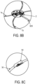
- coils 1a and 1b are connected to and positioned to either side of signal generator 2, a closeup view of which is shown in FIG. 8B .
- Signal generator 2 is coupled to a power source (not shown), such as a battery, a household A/C power source via a power converter, and the like, through wire 505.
- Signal generator 2 includes two (2) drive circuitry units each with control functionality and may be coupled, individually or collectively, to another control device (not shown), such as a general-purpose computing device.
- the control device may provide instructions for signal generation by the drive circuitry units in signal generator 2 via the coils 1a and 1b.
- Each of the two (2) drive circuitry units in signal generator 2 includes a tuning element that is a circuit used to adjust and match an impedance of a PEMF short wave radio frequency generator to an emitter applicator--i.e., a corresponding one of the coils 1a and 1b--post assembly.
- the post assembly impedance adjustments compensate for variability in standard components to optimize radio frequency power output while conforming with ISM bandwidth regulations.
- FDA-cleared PEMF devices use 27.12 MHz as the standard carrier frequency.
- the tuning elements each include, for connecting to respective ones of coils 1a and 1b, a 15kS2 resistor, a 6 pF capacitor, a 27 pF capacitor, and two (2) variable 2 - 10 pF capacitors connected in parallel for operational tuning.
- non-active coils 3a, 3b, 3c, 3d, 3e, and 3f each form non-active coil assemblies in correspondence with assembly 300 with respective non-active circuits 4a, 4b, 4c, 4d, 4e, and 4f in correspondence with circuit 4 illustrated in FIG. 3 and described above.
- a different number of non-active coils that are similar or different in shape and size to coils 3a-3f may be placed in proximity of coils 1a and 1b to form array 800.
- the number of coils 1a and 1b have a general one-to-three relationship with the number of non-active coils 3a-3f.
- Coils 3a-3d have circular shapes of similar dimensions to active coils 1a and 1b, and coils 3e and 3f have oval shapes, with two axes of symmetry (i.e., racetrack shape), and have end-to-end lengths that equal approximately a corresponding end-to-end length of the coils 1a and 1b, each of which having a diameter of approximately 5.5 inches, connected side-by-side through signal generator 2.
- the measured diameters of circular coils 1a-1b and 3a-3d equaled 5.5 inches and the measured dimensions of oval coils 3e and 3f were 2 inches width by 14 inches length.
- FIG. 8C is a closeup view of non-active circuit 4d, which includes the following parameters for components corresponding to those described above with respect to circuit 4 shown in FIG. 2 : a 2 pF capacitor, a 56 pF capacitor, and a 2 - 10 pF variable capacitor connected in parallel for operational tuning with active coils 1a and 1b and the circuit units in signal generator 2.
- Non-active circuits 4a, 4b, and 4c have the same corresponding tuning components.
- Circuits 4e and 4f for oval-shaped loops 3e and 3f have parameters that correspond to those of circuits 4a-4h illustrated in FIGS. 9A and 9B and described in further detail below for EXAMPLE 2.
- circuits 4a-4f are disposed in substrate 805 on sides of non-active coils 3a-3f, respectively, towards active coils 1a and 1b.
- Signal generator 2 generates the above-described treatment signals-i.e., signals with a carrier frequency of 27.12 MHz that are modulated by producing a burst at 2 Hz, such bursts being 2 ms in duration with a peak amplitude of 0.05 Gauss- either simultaneously or sequentially via active coils 1a and 1b.
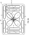
- FIG. 9A is a diagram of an array 900 having four (4) active coils 1c, 1d, 1e, and 1f, and eight (8) non-active coils 3g, 3h, 3i, 3j, 3k, 3l, 3m, and 3n that correspond to coils 1 and 3, respectively, illustrated in FIG. 1 and described above, the coils 1c-1f, and 3g-3n, together with circuits 2b and 4g-4n being disposed in a substrate 905. As shown in FIG. 9A , coils 1c-1f are all connected to a same signal generator 2b, which is powered by a power source through a wire 505.
- different numbers of coils corresponding to coils 1c-1f may be connected to respective signal generators--for example, coils may each be connected to a separate signal generator or plural coils having approximately the same size and shape may be connected together to a single signal generator.
- coils 1c-1f having oval shapes, with one axis of symmetry (i.e. egg shape), are connected to and positioned at respective sides of signal generator 2b, a closeup view of which is shown in FIG. 9B , forming substantially a clover arrangement around signal generator 2b.
- Signal generator 2b is coupled to a power source (not shown), such as a battery, a household A/C power source via a power converter, and the like, through wire 505.
- Signal generator 2b includes four (4) drive circuitry units each with control functionality and may be coupled, individually or collectively, to another control device (not shown), such as a general-purpose computing device.
- the control device may provide instructions for signal generation by the drive circuitry units in signal generator 2b via the coils 1c-1f.
- Each of the four (4) drive circuitry units in signal generator 2b includes a tuning element that is a circuit used to adjust and match an impedance of a PEMF short wave radio frequency generator to an emitter applicator--i.e., a corresponding one of the coils 1c-1f--post assembly.
- the post assembly impedance adjustments compensate for variability in standard components to optimize radio frequency power output while conforming with ISM bandwidth regulations.
- FDA-cleared PEMF devices use 27.12 MHz as the standard carrier frequency.
- the tuning elements each include, for connecting to respective ones of coils 1c-1f, a 10 pF capacitor, a 27 pF capacitor, and two (2) variable 2 - 10 pF capacitors connected in parallel for operational tuning.
- non-active coils 3g, 3h, 3i, 3j, 3k, 3l, 3m, and 3n each form non-active coil assemblies in correspondence with assembly 300 with respective non-active circuits 4g, 4h, 4i, 4j, 4k, 4l, 4m, and 4n in correspondence with circuit 4 illustrated in FIG. 3 and described above.
- a different number of non-active coils that are similar or different in shape and size to coils 3g-3n may be placed in proximity of coils 1c-1f to form array 900.
- the number of coils 1c-1f have a general one-to-two relationship with the number of non-active coils 3g-3n.
- Coils 3g-3n have oval shapes, with two axes of symmetry (i.e., racetrack shape). Active coils 1c-1f have a longer diameter dimension of approximately 7 inches and a shorter diameter dimension of approximately 5 inches at a widest point and 2.75 inches at the respective couplings to signal generator 2b.
- the measured dimensions of oval non-active coils 3g-3n were 2 inches width by 14.5 inches length. Again, it was determined through experimentation that desirable dimensions of oval-shaped non-active coils, such as coils 3g-3n, would approximate an area coverage that is equivalent to a circular area with a 7 inch to 8.5 inch diameter. It was further determined through experimentation that desirable distances among the coils would be between 0.25 to 3 inches, preferably between 0.5 to 2 inches.
- FIG. 9C is a closeup view of non-active circuit 4h, which includes the following parameters for components corresponding to those described above with respect to circuit 4 shown in FIG. 2 : a 43 pF capacitor and a 2 - 10 pF variable capacitor connected in parallel for operational tuning with active coils 1c-1f and the circuit units in signal generator 2b.
- Non-active circuits 4g, 4i, 4j, 4k, 4l, 4m, and 4n have the same corresponding tuning components.
- circuits 4g-4n are disposed in substrate 905 on sides of non-active coils 3g-3n, respectively, towards active coils 1c-1f.
- Signal generator 2b generates the above-described treatment signals-i.e., signals with a carrier frequency of 27.12 MHz that are modulated by producing a burst at 2 Hz, such bursts being 2 ms in duration with a peak amplitude of 0.05 Gauss- either simultaneously or sequentially via active coils 1c, 1d, 1e, and 1f.
Landscapes
- Health & Medical Sciences (AREA)
- Engineering & Computer Science (AREA)
- Biomedical Technology (AREA)
- Nuclear Medicine, Radiotherapy & Molecular Imaging (AREA)
- Radiology & Medical Imaging (AREA)
- Life Sciences & Earth Sciences (AREA)
- Animal Behavior & Ethology (AREA)
- General Health & Medical Sciences (AREA)
- Public Health (AREA)
- Veterinary Medicine (AREA)
- Magnetic Treatment Devices (AREA)
- Treatments Of Macromolecular Shaped Articles (AREA)
Description
- The invention relates to an apparatus for efficient distribution of pulsed electromagnetic waveforms for targeted pulsed electromagnetic field (PEMF) treatment of living humans and animals, tissues and cells utilizing a combination of active and non-active coils. The invention relates also to a corresponding in vitro or ex vivo method for treating a cell, tissue or organ.
- This apparatus and method relates to the more efficient treatment of living humans, animals, tissues, cells and/or organs by altering their interaction with their electromagnetic environment. The disclosure also relates to a method of modification of cellular and tissue growth, repair, maintenance, and general behavior by the application of encoded electromagnetic information. More particularly, this disclosure provides a device for the application, by surgically non-invasive reactive coupling, of highly specific electromagnetic signal patterns to one or more body parts through an arrangement of active coils inductively coupled to non-active coils upon or within a surface where a human or animal would lie upon or coupled within a garment, bandage or other carrier to apply the output of the inductive coil arrangement to a body, area or part.
- An apparatus for pulsed electromagnetic field treatment comprising active and non-active coils and a tunable circuit is known from
US 2008/215115 A1 . - The invention is defined in the appended claims.
- The present disclosure relates to the use of lightweight flexible active coils that are energized with specific electromagnetic waveforms which may be placed within a mattress, pad, cushioned or non-cushioned substrate to provide application of the therapeutic output while the human or animal is lying thereupon or while a pad, mat, blanket, or the like, incorporating the coils is placed on the human or animal subject. In addition, the inductive coil arrangement can be placed in an appropriate garment, bandage or dressing to deliver the optimum dose of non-invasive pulsed electromagnetic treatment for enhanced repair and growth of living tissue in humans and animals. For example,
U.S. Patent Nos. 7,744,524 ,7,740,574 ,7,758,490 ,7,896,797 ,8,343,027 ,8,415,123 ,8,961,385 ,9,320,913 9,415,233 9,433,797 10,350,428 - The disclosed method more particularly includes the provision of a flux path, to an entire human or animal body by incorporating one or more inductive coil arrangements within a surface upon which an animal or human may lie upon during treatment. One or more inductive coil arrangements can be applied to provide a flux path to a selectable body region, of a succession of EMF pulses having a minimum width characteristic of at least 0.01 microseconds in a pulse burst envelope having between 100 and 10,000 pulses per burst, in which a voltage amplitude envelope of said pulse burst is defined by a randomly varying parameter in which the instantaneous minimum amplitude thereof is not smaller than the maximum amplitude thereof by a factor of one ten thousandth. Further, the repetition rate of such pulse bursts may vary from 0.01 to 1,000 Hertz. In special cases a mathematically definable parameter may be employed in lieu of said random amplitude envelope of the pulse bursts.
- It is, accordingly, an object of the invention to provide an improved apparatus for the beneficial treatment of living human and animal bodies, cells, tissue and organs by proscribing an area circumscribed by the combination of active and non-active coils arranged within a mattress, pad, cushioned or non-cushioned surface upon which an animal or human would lie upon thereby allowing for treatment of the entire body or parts thereof while the human or animal is lying upon such surface.
- It is a further object of the invention to provide an apparatus for the delivery of electromagnetic radiation by employing a larger surface area without the need to apply energy to each coil in the surface, but in the use of a combination of one or more active coils that would inductively couple with non-active coils that would be configured to be charged with the electromagnetic output from the active coils. The combination and arrangement of active and non-active coils allows for the treatment of larger areas by situating an active coil to be inductively coupling with one or more non-active coils thereby disbursing the energy from the active coil across the areas of the adjacent non-active coils.
- It is a further object of this invention that the active coil is powered by an electronic generator that produces the desired EMF signal and applies it to the active coil.
- It is another object of this invention that the non-active coils duplicate the output signal from the active coil to act simultaneously as a receiver and transmitter without requiring electrical power by such non-active coils being inductively coupled to the active coils with a tuned circuit adjusted to the active coil output parameters.
- It is a further object to provide a combination of flexible, lightweight active and non-active coils which focus the EMF signal to affected body areas by incorporation in ergonomic support garments.
- It is another object to provide an electromagnetic treatment method of the above type having a broad-band, high spectral density electromagnetic field.
- Further described is a method of the above type in which amplitude and burst duration modulation of the pulse burst envelope of the electromagnetic signal will provide optimal coupling with a maximum number of relevant EMF-sensitive pathways in cells or tissues.
- Also described is utilization of conductive thread to create active and non-active coil arrangements incorporated in daily wear, exercise and sports garments with integrated coils placed according to the desired anatomical target.
- Further described is utilization of a combination of active and non-active lightweight flexible coils or conductive thread to deliver the EMF signal to affected tissue by incorporating such coils or conductive threads as an integral part of various types of bandages, including, but not limited to, compression, elastic, cold or hot compress, etc.
- It is another object of the disclosure to employ several combinations of active and non-active coils which increase the coverage area.
- It is another object of the disclosure to supply the same or different waveforms simultaneously or sequentially to single or multiple inductive coils arrangements.
- It is another object of the present disclosure to construct the inductive coil apparatus for easy attachment to dressings, garments and supports via the use of hook and loop (Velcro®), adhesive or other such temporary attachment means.
- It is another object of the disclosure to provide an improved method of increasing blood flow to affected tissues by modulating angiogenesis.
- It is another object of the disclosure to provide an improved method of increasing blood flow in cardiovascular diseases by modulating angiogenesis.
- It is another object of the disclosure to provide beneficial physiological effects through improvement of micro-vascular blood perfusion and reduced transudation.
- It is another object of the disclosure to provide an improved method of treatment of maladies of the bone and other hard tissue.
- It is a still further object of the disclosure to provide an improved means of the treatment of edema and swelling of soft tissue.
- It is another object to provide a means of repair of damaged soft tissue.
- It is yet another object to provide a means of increasing blood flow to damaged tissue by modulation of vasodilation and stimulating neovascularization.
- It is a yet further object to provide apparatus for use of an electromagnetic method of the character indicated, wherein operation of the apparatus can proceed at reduced power levels as compared to those of related methods known in electromedicine, with attendant benefits of safety, economics, portability, and reduced electromagnetic interference.
- It is a yet further object to provide an active and non-active coil apparatus for use of an electromagnetic method of the character indicated, wherein operation of the apparatus can proceed at reduced power levels as compared to those of related methods known in electromedicine, with attendant benefits of safety, economics, portability, and reduced electromagnetic interference and the reduced cost related to the use of the non-active coils to further disperse the treatment area.
- The methods of treatment of a living subject described in this disclosure are provided for illustrative purposes and do not form a part of the claimed subject-matter.
- An inductive applicator coil arrangement apparatus and method is described which allows broad spectral density bursts of electromagnetic waveforms to be applied to an active coil placed within proximity of one or more non-active coils. The non-active coils are configured to be inductively coupled to, and energized by, the active coil thereby dispersing the therapeutic output across the larger area circumscribed by the combination of active and non-active coils, to be selectively applied to a living human or animal body (or to living cells, tissues and organs) for therapeutic purposes. The active coil electromagnetic waveform output has a frequency in the range of one (1) to one hundred (100) megahertz, with one (1) to one hundred thousand (100,000) pulses per burst, and with a burst-repetition rate of one hundredth (0.01) to one thousand (1,000) Hertz. The inductive applicator coil arrangement can be placed within a mattress, pad, cushioned or non-cushioned substrate to provide application of the therapeutic output while the human or animal is lying thereupon. In addition, one or more inductive applicator coil arrangements can be placed adjacent to the tissue target by incorporating within a garment, bandage or support fabricated with compartments or sections to house the coils at appropriate anatomical locations. The inductive applicator coil arrangement may also form an integral portion of a garment designed for daily, exercise or sports use through the use of conductive thread or fine, flexible wire. The garment may be for exercise, sports, physical rehabilitation or as a post-surgical, non-invasive, non-pharmacological anti-inflammatory therapeutic modality. The inductive applicator coil arrangement may be incorporated into or be an integral part of various types of bandages, including, but not limited to, compression, elastic, cold or hot compress, etc. The waveforms applied by the active and non-active coils of the present invention were configured for maximum efficiency allowing the complete electromagnetic treatment system to be lightweight, battery operated and portable. The waveforms are designed to modulate living cell growth and repair. Particular applications of the present invention include, but are not limited to, angiogenesis, improved micro-vascular blood perfusion, vasodilation, reduced transudation, stimulation of neovascularization bone repair, wound repair, pain relief, edema reduction, increased blood flow and to provide anti-inflammatory effects.
- The above and yet other objects and advantages of the present invention will become apparent from the hereinafter set forth Brief Description of the Drawings.
- It is intended that any other advantages and objects of the present invention that become apparent or obvious from the detailed description, drawings or illustrations contained herein are within the scope of the present invention as defined by the claims.
-
-
FIG. 1 is a diagram of a treatment apparatus coil array having an active coil and a non-active coil according to an exemplary embodiment of the invention. -
FIG. 2 is a schematic diagram of a tunable circuit for coupling to the non-active coil ofFIG. 1 according to an exemplary embodiment of the invention. -
FIG. 3 is an image of a non-active coil according to an exemplary embodiment of the invention. -
FIG. 4 is an image of a tunable circuit corresponding to the tunable circuit ofFIG. 2 in accordance with an exemplary embodiment of the invention. -
FIG. 5 is an image of a treatment apparatus coil array having two (2) active coils and two (2) non-active coils (with APB-FX001 test fixture) according to an exemplary embodiment of the invention. -
FIG. 6 is a diagram showing a testing assembly for the treatment apparatus coil array ofFIG. 5 in accordance with an exemplary embodiment of the invention. -
FIGs. 7A ,7B , and7C are output diagrams showing test results from the testing assembly ofFIG. 6 according to an exemplary embodiment of the invention. -
FIG. 8A is a diagram illustrating a coil array for a treatment apparatus having two (2) active coils and six (6) non-active coils according to an exemplary embodiment of the invention. -
FIG. 8B is a closeup view of a signal generator coupled to the active coils in the coil array shown inFIG. 8A . -
FIG. 8C is a closeup view of a tunable non-active circuit coupled to a non-active coil in the coil array shown inFIG. 8A . -
FIG. 9A is a diagram illustrating a coil array for a treatment apparatus having four (4) active coils and eight (8) non-active coils according to an exemplary embodiment of the invention. -
FIG. 9B is a closeup view of a signal generator coupled to the active coils in the coil array shown inFIG. 9A . -
FIG. 9C is a closeup view of a tunable non-active circuit coupled to a non-active coil in the coil array shown inFIG. 9A . -
FIG. 1 is a diagram of a treatment apparatus coil array having an active coil and a non-active coil according to an exemplary embodiment of the invention. As shown inFIG. 1 , a treatmentapparatus coil array 100 according to an embodiment of the invention may comprise at least onewire loop 1 forming a coil, asignal generator 2 which is powered by an electrical power supply for generating a PEMF signal to be transmitted via the coil (hereinafter also referred to as wire loop) 1 and, thereby, providing a treatment signal directed towards a human or animal subject by placing thecoil 1 proximate a treatment target of the subject.Signal generator 2 may comprise drive circuitry coupled to a power source, such as a battery, a household A/C power source via a power converter, and the like. - According to an embodiment of the invention,
array 100 may further comprise one or more additional coils (or wire loops), for example,coil 3 that is coupled to a tunedpassive circuit 4.Circuit 4 is configured to be induced by thesignal generator 2 viacoils proximate loop 3 without requiring a separate electrical power connection.Loop 3 andcircuit 4 function together to output a signal based on the signal output fromloop 1 andsignal generator 2. In accordance with an exemplary embodiment of the invention,circuit 3 may be tuned according to the signal fromloop 1 andsignal generator 2 so that a treatment signal output fromloop 3 is an approximate duplicate of the treatment signal output fromloop 1. Consequently, an approximately uniform treatment signal field may be generated acrossloops coil coil coils Coils array 100 may be mounted to a substrate, such as incorporated within a cushioned sleeve between two cushion layers that are made from, for example, foam rubber and the like. Alternatively, the coils may be embedded within a soft polymer enclosure to one side of a cushion layer. Depending upon the treatment depth needed for a patient, the treatment surface for such a treatment pad/bed may be on the polymer enclosure side or the cushion layer side. In addition, each of thecoils bed incorporating array 100 may be disposed within, for example, a pet carrier for treating small pet animals while transporting the treatment subject. -
FIG. 2 is a schematic diagram oftunable circuit 4 for coupling to thenon-active coil 3 ofFIG. 1 according to an exemplary embodiment of the invention. As shown inFIG. 2 ,circuit 4 may comprise one or more capacitors--for example, three (3) as illustrated inFIG. 2 -- connected in parallel with one or more resistors--for example, one (1) as illustrated inFIG. 2 . In order to provide for the tuning according to the signal transmitted fromgenerator 2 viacoil 1,circuit 4 comprises an additionalvariable capacitor 5 connected in parallel to the one or more (e.g., three)capacitors variable capacitor 5 may be a trimmer/variable capacitor with a 6.5 - 30 pF range at 100 V (N120), the resistor 9 may be a15K Ohm 1% 1/10W (0603) resistor, and the one ormore capacitors variable capacitor 5, the one ormore capacitors circuit 4 may be adjusted according to the sizes ofcoils - Again, the assembly formed by
coil 3 andcircuit 4 can act as both a receiver and transmitter without requiring electrical power and all the circuitry ofsignal generator 2.FIG. 3 is an image ofnon-active coil assembly 300 formed bycoil 3 andcircuit 4 according to an exemplary embodiment of the invention. As described above and as shown inFIG. 3 ,assembly 300 may comprisecoil 3 that is formed in a shape that is not strictly circular-such as, for example, oval or racetrack-shaped--in order to accommodate various kinds of arrays, pads, beds, enclosures, carriers, patients, and corresponding treatment depth. -
FIG. 4 is an image ofcircuit 4 connected tocoil 3 and illustratingvariable capacitor 400 for convenient tuning ofcircuit 4. According to an embodiment of the invention,circuit 4 may be disposed within an enclosure after tuning ofvariable capacitor 400 is completed. -
FIG. 5 is an image of anarray 500 havingcoils coils FIG. 1 and described above. As shown inFIG. 5 , coils 1a and 1b may both be connected to asame signal generator 2, which is powered by a power source through awire 505 to apower source connector 510. According to an exemplary embodiment of the invention, different numbers of coils corresponding tocoils FIG. 5 , coils 3a and 3b may each formnon-active coil assemblies non-active circuits assembly 300 illustrated inFIG. 3 and described above. Correspondingly, a different number of non-active coils that are similar or different in shape and size tocoils coils array 500. For the illustrated exemplary embodiment, coils 1a and 1b have a one-to-one relationship withnon-active coils coils coil coil 1a/1b tocircuit 4a/4b shown inFIG. 5 . For testing and/or tuning purposes,array 500 may be place in a test fixture, such as the APB-FX001 Test Fixture shown inFIG. 5 . -
FIG. 6 is a diagram showing atesting assembly 600 for the treatmentapparatus coil array 500 ofFIG. 5 in accordance with an exemplary embodiment of the invention. As shown inFIG. 6 , an oscilloscope (e.g., Tektronix® TDS 2012B or equivalent) with respective RF probes attached thereto (along with, for example, respective 50 Ohm Feed-through Adapters) may be used to measure the treatment signal outputs of therespective coils array 500. For testing described below, the probes were placed at the center of therespective coils coils circuits circuits coils FIG. 6 , testing assembly may comprise a mini controller for controlling and adjusting the output ofsignal generator 2. According to an exemplary embodiment of the invention,signal generator 2 may be integrated with a controller that provides control and output functionality that corresponds to the mini controller shown inFIG. 6 for, as an example,programming array 500 in a treatment apparatus using an onboard or wireless user interface, and the like. -
FIGs. 7A ,7B , and7C are output diagrams of the oscilloscopes oftesting assembly 600 shownFIG. 6 according to an exemplary embodiment of the invention. - In particular,
FIG. 7A shows the outputs of the oscilloscopes with the RF probes placed at the center positions described above with respect tocoils FIG. 5 but without incorporatingcoils assembly 600 shown inFIG. 6 --i.e., showing the treatment signal levels at the respective positions without incorporatingnon-active coil assemblies FIG. 7A ,signal generator 2, as controlled by the mini controller shown inFIG. 6 , causescoils coils -
FIG. 7B shows the outputs of the oscilloscopes with the RF probes placed at the center positions described above with respect tocoils FIG. 5 and incorporatingcoils assembly 600 shown inFIG. 6 but without tuningnon-active coil assemblies signal generator 2 andcoils FIG. 7B ,signal generator 2, as controlled by the mini controller shown inFIG. 6 and which corresponds to the signal input forFIG. 7A , causescoils coils array 500 reflects an undesirable non-uniform treatment signal field (i.e., resulting in a less than optimal treatment field for the array), which may also result in undue power drain from the electric energy source (such as a battery) forsignal generator 2. -
FIG. 7C shows the outputs of the oscilloscopes with the RF probes placed at the center positions described above with respect tocoils FIG. 5 and incorporatingcoils assembly 600 shown inFIG. 6 and withnon-active coil assemblies respective circuit 4--being tuned to the signals output fromsignal generator 2 andcoils FIG. 7C ,signal generator 2, as controlled by the mini controller shown inFIG. 6 and which corresponds to the signal input forFIGs. 7A and7B , causescoils coils array 500 provided a more uniform treatment signal field that is consistently above the desirable 130 mV level. According to an exemplary embodiment of the invention, the variable capacitors of thecircuits coils 1a/1b and 3a/3b, as described above, are within a 5% - 40% range of each other, or preferably within a 5% - 20% range of each other, or more preferably within a 5% - 15% range of each other. - As a result, with appropriate tuning, one or more non-active coil assemblies corresponding to assembly 300 (300a and 300b) shown and described above may be placed in the vicinity of one or more "active" coils--corresponding to
coils - Based on the above-described tuning, a device as described herein can be configured so that it applies a bio-effective waveform for a predetermined amount of time using a predetermined (or modifiable) treatment regime. In one variation, the signal frequency within a particular burst envelope is centered on a particular carrier frequency (e.g., 27.12 MHz, 6.78 MHz, etc.). For example, the waveform within a burst may use a carrier frequency of 6.78 MHz and the frequency between bursts can be modulated by producing bursts at 1 Hz. In one variation, bursts are 7 ms in duration with a peak amplitude of 0.05 Gauss. In another example, a device can be configured using a carrier frequency of 27.12 MHz that can be modulated by producing a burst at 2 Hz, such bursts being 2 ms in duration with a peak amplitude of 0.05 Gauss. In some variations, the device is configured to explicitly limit the peak signal strength of the applied signal. For example, the peak signal strength may be limited to approximately 50 milliGauss (e.g., 0.05 Gauss). A proper signal configuration to produce the necessary induced electric fields in the range of 0.1-100 millivolts per centimeter ("mV/cm") for a given carrier frequency may be determined as described herein. In general, the desired and specific effect seen on the target pathway (e.g., the Ca/CaM pathway) may be very sensitive to the waveform parameters. The ranges of waveform parameters described herein are tuned to the desired effect.
-
FIG. 8A is a diagram of anarray 800 having two (2)active coils non-active coils coils FIG. 1 and described above, thecoils circuits substrate 805. As shown inFIG. 8A , coils 1a and 1b are both connected to asame signal generator 2, which is powered by a power source through awire 505. In embodiments, different numbers of coils corresponding tocoils - As illustrated in
FIG. 8A , coils 1a and 1b are connected to and positioned to either side ofsignal generator 2, a closeup view of which is shown inFIG. 8B .Signal generator 2 is coupled to a power source (not shown), such as a battery, a household A/C power source via a power converter, and the like, throughwire 505.Signal generator 2 includes two (2) drive circuitry units each with control functionality and may be coupled, individually or collectively, to another control device (not shown), such as a general-purpose computing device. The control device may provide instructions for signal generation by the drive circuitry units insignal generator 2 via thecoils signal generator 2 includes a tuning element that is a circuit used to adjust and match an impedance of a PEMF short wave radio frequency generator to an emitter applicator--i.e., a corresponding one of thecoils coils - As further shown in
FIG. 8A ,non-active coils assembly 300 with respectivenon-active circuits circuit 4 illustrated inFIG. 3 and described above. Correspondingly, in embodiments, a different number of non-active coils that are similar or different in shape and size tocoils 3a-3f may be placed in proximity ofcoils array 800. As illustrated inFIG. 8A , the number ofcoils non-active coils 3a-3f.Coils 3a-3d have circular shapes of similar dimensions toactive coils coils coils signal generator 2. The measured diameters ofcircular coils 1a-1b and 3a-3d equaled 5.5 inches and the measured dimensions ofoval coils coils substrate 805, made from a flexible material, measured 35 inches long and 17 inches wide. -
FIG. 8C is a closeup view ofnon-active circuit 4d, which includes the following parameters for components corresponding to those described above with respect tocircuit 4 shown inFIG. 2 : a 2 pF capacitor, a 56 pF capacitor, and a 2 - 10 pF variable capacitor connected in parallel for operational tuning withactive coils signal generator 2.Non-active circuits Circuits 4e and 4f for oval-shapedloops circuits 4a-4h illustrated inFIGS. 9A and9B and described in further detail below for EXAMPLE 2. - As shown in
FIG. 8A ,circuits 4a-4f are disposed insubstrate 805 on sides ofnon-active coils 3a-3f, respectively, towardsactive coils Signal generator 2 generates the above-described treatment signals-i.e., signals with a carrier frequency of 27.12 MHz that are modulated by producing a burst at 2 Hz, such bursts being 2 ms in duration with a peak amplitude of 0.05 Gauss- either simultaneously or sequentially viaactive coils -
FIG. 9A is a diagram of anarray 900 having four (4)active coils non-active coils coils FIG. 1 and described above, the coils 1c-1f, and 3g-3n, together withcircuits substrate 905. As shown inFIG. 9A , coils 1c-1f are all connected to asame signal generator 2b, which is powered by a power source through awire 505. In embodiments, different numbers of coils corresponding to coils 1c-1f may be connected to respective signal generators--for example, coils may each be connected to a separate signal generator or plural coils having approximately the same size and shape may be connected together to a single signal generator. - As illustrated in
FIG. 9A , coils 1c-1f having oval shapes, with one axis of symmetry (i.e. egg shape), are connected to and positioned at respective sides ofsignal generator 2b, a closeup view of which is shown inFIG. 9B , forming substantially a clover arrangement aroundsignal generator 2b.Signal generator 2b is coupled to a power source (not shown), such as a battery, a household A/C power source via a power converter, and the like, throughwire 505.Signal generator 2b includes four (4) drive circuitry units each with control functionality and may be coupled, individually or collectively, to another control device (not shown), such as a general-purpose computing device. The control device may provide instructions for signal generation by the drive circuitry units insignal generator 2b via the coils 1c-1f. Each of the four (4) drive circuitry units insignal generator 2b includes a tuning element that is a circuit used to adjust and match an impedance of a PEMF short wave radio frequency generator to an emitter applicator--i.e., a corresponding one of the coils 1c-1f--post assembly. The post assembly impedance adjustments compensate for variability in standard components to optimize radio frequency power output while conforming with ISM bandwidth regulations. FDA-cleared PEMF devices use 27.12 MHz as the standard carrier frequency. The tuning elements each include, for connecting to respective ones of coils 1c-1f, a 10 pF capacitor, a 27 pF capacitor, and two (2) variable 2 - 10 pF capacitors connected in parallel for operational tuning. - As further shown in
FIG. 9A ,non-active coils assembly 300 with respectivenon-active circuits circuit 4 illustrated inFIG. 3 and described above. Correspondingly, in embodiments, a different number of non-active coils that are similar or different in shape and size tocoils 3g-3n may be placed in proximity of coils 1c-1f to formarray 900. As illustrated inFIG. 9A , the number of coils 1c-1f have a general one-to-two relationship with the number ofnon-active coils 3g-3n.Coils 3g-3n have oval shapes, with two axes of symmetry (i.e., racetrack shape). Active coils 1c-1f have a longer diameter dimension of approximately 7 inches and a shorter diameter dimension of approximately 5 inches at a widest point and 2.75 inches at the respective couplings to signalgenerator 2b. The measured dimensions of ovalnon-active coils 3g-3n were 2 inches width by 14.5 inches length. Again, it was determined through experimentation that desirable dimensions of oval-shaped non-active coils, such ascoils 3g-3n, would approximate an area coverage that is equivalent to a circular area with a 7 inch to 8.5 inch diameter. It was further determined through experimentation that desirable distances among the coils would be between 0.25 to 3 inches, preferably between 0.5 to 2 inches. The resultingsubstrate 905, made from a flexible material, measured 32.5 inches long and 23.5 inches wide. -
FIG. 9C is a closeup view ofnon-active circuit 4h, which includes the following parameters for components corresponding to those described above with respect tocircuit 4 shown inFIG. 2 : a 43 pF capacitor and a 2 - 10 pF variable capacitor connected in parallel for operational tuning with active coils 1c-1f and the circuit units insignal generator 2b.Non-active circuits - As shown in
FIG. 9A ,circuits 4g-4n are disposed insubstrate 905 on sides ofnon-active coils 3g-3n, respectively, towards active coils 1c-1f.Signal generator 2b generates the above-described treatment signals-i.e., signals with a carrier frequency of 27.12 MHz that are modulated by producing a burst at 2 Hz, such bursts being 2 ms in duration with a peak amplitude of 0.05 Gauss- either simultaneously or sequentially viaactive coils - While particular embodiments of the present invention have been shown and described in detail, it would be obvious to those skilled in the art that various modifications and improvements thereon may be made without departing from the scope of the invention.
- It is therefore intended to cover in the appended claims all such modifications and improvements that are within the scope of this invention.
Claims (11)
- An apparatus for providing pulsed electromagnetic field (PEMF) treatment, comprising:a substrate (805, 905);one or more first electrically-conductive loops (1, 1a, 1b, 1c, 1d, 1e, 1f) on the substrate (805, 905) connected to one or more corresponding signal generators (2, 2b) configured to generate one or more PEMF signals at the one or more first electrically-conductive loops (1, 1a, 1b, 1c, 1d, 1e, 1f);one or more tunable non-active circuits (4, 4a, 4b, 4c, 4d, 4e, 4f, 4g, 4h, 4i, 4j, 4k, 4l, 4m, 4n);one or more second electrically-conductive loops (3, 3a, 3b, 3c, 3d, 3e, 3f, 3g, 3h, 3i, 3j, 3k, 3l, 3m, 3n) each connected to a respective tunable non-active circuit (4, 4a, 4b, 4c, 4d, 4e, 4f, 4g. 4h, 4i, 4j, 4k, 4l, 4m, 4n), the one or more second electrically-conductive loops (3, 3a, 3b, 3c, 3d, 3e, 3f, 3g, 3h, 3i, 3j, 3k, 3l, 3m, 3n) being arranged at a predetermined distance from the one or more first electrically-conductive loops (1, 1a, 1b, 1c, 1d, 1e, 1f) on the substrate (805, 905) to form an array (100, 500, 800, 900),wherein each tunable non-active circuit (4, 4a, 4b, 4c, 4d, 4e, 4f, 4g. 4h, 4i, 4j, 4k, 4l, 4m, 4n) comprises at least one variable capacitor (5, 400) for tuning each of the one or more second electrically-conductive loops (3, 3a, 3b, 3c, 3d, 3e, 3f, 3g, 3h, 3i, 3j, 3k, 3l, 3m, 3n) to the one or more PEMF signals;whereinthe one or more first electrically-conductive loops (1, 1a, 1b, 1c, 1d, 1e, 1f) are active loops and the one or more second electrically-conductive loops (3, 3a, 3b, 3c, 3d, 3e, 3f, 3g, 3h, 3i, 3j, 3k, 3l, 3m, 3n) are non-active loops,characterized in thatthe non-active loops (3, 3a, 3b, 3c, 3d, 3e, 3f, 3g, 3h, 3i, 3j, 3k, 3l, 3m, 3n) duplicate the output signal from the active loops (1, 1a, 1b, 1c, 1d, 1e, 1f) to act simultaneously as a receiver and transmitter without requiring electrical power by such non-active loops (3, 3a, 3b, 3c, 3d, 3e, 3f, 3g, 3h, 3i, 3j, 3k, 3l, 3m, 3n) thereby providing increased area of coverage of a treatment signal field,such non-active loops (3, 3a, 3b, 3c, 3d, 3e, 3f, 3g, 3h, 3i, 3j, 3k, 3l, 3m, 3n) being inductively coupled to the active loops (1, 1a, 1b, 1c, 1d, 1e, 1f) with the tunable non-active circuit adjusted to the active loop output parameters to provide a more uniform treatment signal field,wherein the non-active loops (3, 3a, 3b, 3c, 3d, 3e, 3f, 3g, 3h, 3i, 3j, 3k, 3l, 3m, 3n) are formed in a shape that is circular, D-shaped or oval.
- The apparatus of claim 1, wherein each of the first (1, 1a, 1b, 1c, 1d. 1e, 1f) and second (3, 3a, 3b, 3c, 3d, 3e, 3f, 3g, 3h, 3i, 3j, 3k, 3l, 3m, 3n) electrically-conductive loops has a diameter of between approximately 10 cm (4 inches) and 20 cm (8 inches).
- The apparatus of claim 1, wherein the one or more first electrically-conductive loops (1, 1a, 1b, 1c, 1d, 1e, 1f) comprise two first electrically-conductive loops connected to two corresponding signal generators (2, 2b) and the one or more second electrically-conductive loops (3, 3a, 3b, 3c, 3d, 3e, 3f, 3g, 3h, 3i, 3j, 3k, 3l, 3m, 3n) comprise a plurality of second electrically-conductive loops connected to respective tunable non-active circuits (4, 4a, 4b, 4c, 4d, 4e, 4f, 4g. 4h, 4i, 4j, 4k, 4l, 4m, 4n).
- The apparatus of claim 3, wherein the two corresponding signal generators (2, 2b) simultaneously transmit respective radio frequency signals via the two first electrically-conductive loops (1, 1a, 1b, 1c, 1d, 1e, 1f).
- The apparatus of claim 3, wherein the two corresponding signal generators (2, 2b) transmit respective radio frequency signals consecutively via the two first electrically-conductive loops (1, 1a, 1b, 1c, 1d, 1e, 1f).
- The apparatus of claim 1, wherein the one or more first electrically-conductive loops (1, 1a, 1b, 1c, 1d, 1e, 1f) comprise four first electrically-conductive loops connected to four corresponding signal generators (2, 2b) and the one or more second electrically-conductive loops (3, 3a, 3b, 3c, 3d, 3e, 3f, 3g, 3h, 3i, 3j, 3k, 3l, 3m, 3n) comprise four or more second electrically-conductive loops connected to respective tunable non-active circuits (4, 4a, 4b, 4c, 4d, 4e, 4f, 4g. 4h, 4i, 4j, 4k, 4l, 4m, 4n).
- The apparatus of claim 6, wherein the four corresponding signal generators (2, 2b) simultaneously transmit respective radio frequency signals via the four first electrically-conductive loops (1, 1a, 1b, 1c, 1d, 1e, 1f).
- The apparatus of claim 6, wherein the four corresponding signal generators (2, 2b) transmit respective radio frequency signals consecutively via the four first electrically-conductive loops (1, 1a, 1b, 1c, 1d, 1e, 1f).
- The apparatus of claim 1, wherein the substrate (805, 905) comprises a flexible material.
- An in vitro or ex vivo method for treating a cell, tissue or organ of a subject by applying one or more pulsed electromagnetic field (PEMF) treatment signals, comprising:providing an array (100, 500, 800, 900) of a plurality of loop antennas (1, 1a, 1b, 1c, 1d, 1e, 1f), comprising at least one active loop antenna which is coupled to a corresponding one or more signal generator circuits (2, 2b) on a substrate (805, 905) configured to mount at least the array of the plurality of loop antennas (1, 1a, 1b, 1c, 1d, 1e, 1f), said substrate (805, 905) comprising a treatment surface configured to be placed proximate the cell, tissue or organ of said subject; andactivating the one or more signal generator circuits (2, 2b) to generate the one or more PEMF treatment signals to the corresponding at least one active loop antennas (1, 1a, 1b, 1c, 1d, 1e, 1f),wherein the array (100, 500, 800, 900) of the plurality of loop antennas further comprises at least one non-active loop antenna (3, 3a, 3b, 3c, 3d, 3e, 3f, 3g, 3h, 3i, 3j, 3k, 3l, 3m, 3n), each of the at least one non-active loop antenna connected to a respective tunable non-active circuit (4, 4a, 4b, 4c, 4d, 4e, 4f, 4g. 4h, 4i, 4j, 4k, 4l, 4m, 4n) having at least one variable capacitor (5, 400) for tuning the respective tunable non-active circuit (4, 4a, 4b, 4c, 4d, 4e, 4f, 4g. 4h, 4i, 4j, 4k, 4l, 4m, 4n) to the one or more PEMF treatment signals generated by the one or more signal generator circuits (2, 2b);characterized in thatthe at least one non-active loop antenna (3, 3a, 3b, 3c, 3d, 3e, 3f, 3g, 3h, 3i, 3j, 3k, 3l, 3m, 3n) duplicates the output signal from active loop antennas (1, 1a, 1b, 1c, 1d, 1e, 1f) to act simultaneously as a receiver and transmitter without requiring electrical power by such at least one non-active loop antenna (3, 3a, 3b, 3c, 3d, 3e, 3f, 3g, 3h, 3i, 3j, 3k, 3l, 3m, 3n) thereby providing increased area of coverage of a treatment signal field,the at least one non-active loop antenna (3, 3a, 3b, 3c, 3d, 3e, 3f, 3g, 3h, 3i, 3j, 3k, 3l, 3m, 3n) being inductively coupled to the active loop antennas (1, 1a, 1b, 1c, 1d, 1e, 1f) with the tunable non-active circuit adjusted to the active loop output parameters to provide a more uniform treatment signal field,wherein the at least one non-active loop antenna (3, 3a, 3b, 3c, 3d, 3e, 3f, 3g, 3h, 3i, 3j, 3k, 3l, 3m, 3n) is formed in a shape that is circular, D-shaped or oval.
- A method of manufacturing an apparatus for treating a subject by applying one or more pulsed electromagnetic field (PEMF) signals, comprising:coupling one or more first loop antennas (1, 1a, 1b, 1c, 1d, 1e, 1f) to a corresponding one or more signal generator circuits (2, 2b);placing one or more second loop antennas (3, 3a, 3b, 3c, 3d, 3e, 3f, 3g, 3h, 3i, 3j, 3k, 3l, 3m, 3n), each connected to a tunable non-active circuit (4, 4a, 4b, 4c, 4d, 4e, 4f, 4g. 4h, 4i, 4j, 4k, 4l, 4m, 4n) comprising at least one variable capacitor (5, 400), at a predetermined inductive coupling compatible distance from the one or more first loop antennas (1, 1a, 1b, 1c, 1d, 1e, 1f) to form an array (100, 500, 800, 900), wherein each tunable non-active circuit (4, 4a, 4b, 4c, 4d, 4e, 4f, 4g. 4h, 4i, 4j, 4k, 4l, 4m, 4n) is tunable by adjusting the respective at least one variable capacitor (5, 400) according to a detected output from the one or more signal generator circuits (2, 2b); andproviding a substrate (805, 905) for mounting the array (100, 500, 800, 900);whereinthe one or more first loop antennas (1, 1a, 1b, 1c, 1d, 1e, 1f) are active loop antennas and the one or more second loop antennas (3, 3a, 3b, 3c, 3d, 3e, 3f, 3g, 3h, 3i, 3j, 3k, 3l, 3m, 3n) are non-active loop antennas,characterized in thatthe non-active loop antennas (3, 3a, 3b, 3c, 3d, 3e, 3f, 3g, 3h, 3i, 3j, 3k, 3l, 3m, 3n) duplicate the output signal from active loop antennas (1, 1a, 1b, 1c, 1d, 1e, 1f) to act simultaneously as a receiver and transmitter without requiring electrical power by such non-active loop antennas (3, 3a, 3b, 3c, 3d, 3e, 3f, 3g, 3h, 3i, 3j, 3k, 3l, 3m, 3n) thereby providing increased area of coverage of a treatment signal field,the non-active loop antennas (3, 3a, 3b, 3c, 3d, 3e, 3f, 3g, 3h, 3i, 3j, 3k, 3l, 3m, 3n) being inductively coupled to the active loop antennas (1, 1a, 1b, 1c, 1d, 1e, 1f) with the tunable non-active circuit adjusted to the active loop output parameters to provide a more uniform treatment signal field,wherein the non-active loop antennas (3, 3a, 3b, 3c, 3d, 3e, 3f, 3g, 3h, 3i, 3j, 3k, 3l, 3m, 3n) are formed in a shape that is circular, D-shaped or oval.
Applications Claiming Priority (2)
| Application Number | Priority Date | Filing Date | Title |
|---|---|---|---|
| US201862747446P | 2018-10-18 | 2018-10-18 | |
| PCT/US2019/056736 WO2020081813A1 (en) | 2018-10-18 | 2019-10-17 | Inductive applicator coil arrangement for therapeutically treating human and animal bodies |
Publications (4)
| Publication Number | Publication Date |
|---|---|
| EP3873593A1 EP3873593A1 (en) | 2021-09-08 |
| EP3873593A4 EP3873593A4 (en) | 2022-07-13 |
| EP3873593B1 true EP3873593B1 (en) | 2024-02-21 |
| EP3873593C0 EP3873593C0 (en) | 2024-02-21 |
Family
ID=70284777
Family Applications (1)
| Application Number | Title | Priority Date | Filing Date |
|---|---|---|---|
| EP19872967.5A Active EP3873593B1 (en) | 2018-10-18 | 2019-10-17 | Inductive applicator coil arrangement for therapeutically treating human and animal bodies |
Country Status (9)
| Country | Link |
|---|---|
| US (1) | US11135442B1 (en) |
| EP (1) | EP3873593B1 (en) |
| CN (1) | CN112912136B (en) |
| AU (1) | AU2019359880B2 (en) |
| CA (1) | CA3116229C (en) |
| ES (1) | ES2985893T3 (en) |
| SG (1) | SG11202102457WA (en) |
| TW (1) | TWI789554B (en) |
| WO (1) | WO2020081813A1 (en) |
Families Citing this family (3)
| Publication number | Priority date | Publication date | Assignee | Title |
|---|---|---|---|---|
| IT202100018377A1 (en) * | 2021-07-13 | 2023-01-13 | Led S P A | MAGNETIC FIELD MEDICAL DEVICE CONSISTING OF INTELLIGENT ANTENNAS |
| IT202100032270A1 (en) * | 2021-12-22 | 2023-06-22 | Ethidea S R L | ADAPTIVE DEVICE FOR SYNTHESIS AND DELIVERY OF MODULATED ELECTROMAGNETIC SEQUENCES |
| EP4356958A1 (en) * | 2022-10-17 | 2024-04-24 | Led S.p.A. | Magnetic field medical device constituted by intelligent antennas |
Family Cites Families (25)
| Publication number | Priority date | Publication date | Assignee | Title |
|---|---|---|---|---|
| US2656839A (en) * | 1950-02-14 | 1953-10-27 | Clarence B Howard | Electrotherapeutic oscillator |
| US3566877A (en) * | 1968-01-05 | 1971-03-02 | Luther B Smith | Electrotherapeutic apparatus and treatment head and method for tuning said treatment head |
| US5058582A (en) * | 1983-06-29 | 1991-10-22 | Sheldon Thaler | Apparatus for reactively applying electrical energy pulses to a living body |
| US6094599A (en) * | 1998-03-24 | 2000-07-25 | Ehti Medical Corporation | RF diathermy and faradic muscle stimulation treatment |
| US9433797B2 (en) | 2003-12-05 | 2016-09-06 | Rio Grande Neurosciences, Inc. | Apparatus and method for electromagnetic treatment of neurodegenerative conditions |
| US7744524B2 (en) | 2003-12-05 | 2010-06-29 | Ivivi Health Sciences, Llc | Apparatus and method for electromagnetic treatment of plant, animal, and human tissue, organs, cells, and molecules |
| US8961385B2 (en) | 2003-12-05 | 2015-02-24 | Ivivi Health Sciences, Llc | Devices and method for treatment of degenerative joint diseases with electromagnetic fields |
| US9415233B2 (en) | 2003-12-05 | 2016-08-16 | Rio Grande Neurosciences, Inc. | Apparatus and method for electromagnetic treatment of neurological pain |
| US10350428B2 (en) | 2014-11-04 | 2019-07-16 | Endonovo Therapetics, Inc. | Method and apparatus for electromagnetic treatment of living systems |
| US20110112352A1 (en) * | 2003-12-05 | 2011-05-12 | Pilla Arthur A | Apparatus and method for electromagnetic treatment |
| US7758490B2 (en) | 2005-09-10 | 2010-07-20 | Ivivi Health Sciences, Llc | Integrated coil apparatus for therapeutically treating human and animal cells, tissues and organs with electromagnetic fields and method for using same |
| NZ551316A (en) | 2004-04-19 | 2008-03-28 | Ivivi Technologies Inc | Electromagnetic treatment apparatus and method |
| MXPA06012389A (en) | 2004-04-26 | 2007-05-23 | Ivivi Technologies Inc | Electromagnetic treatment induction apparatus and method. |
| US8147395B2 (en) * | 2006-11-28 | 2012-04-03 | Gregory S. Anderson | Bone-activity stimulation apparatus and method |
| CA2688722A1 (en) | 2007-04-12 | 2008-10-23 | Ivivi Technologies, Inc. | Electromagnetic field treatment apparatus and method for using same |
| EP2493551A4 (en) * | 2009-10-26 | 2013-04-17 | Emkinetics Inc | Method and apparatus for electromagnetic stimulation of nerve, muscle, and body tissues |
| WO2012029065A2 (en) * | 2010-09-05 | 2012-03-08 | Venus Concept Ltd | A self operated esthetic device with a substrate |
| GB201021032D0 (en) * | 2010-12-10 | 2011-01-26 | Creo Medical Ltd | Electrosurgical apparatus |
| ITTO20110527A1 (en) * | 2011-06-15 | 2012-12-16 | Bruno Massimo Cetroni | APPARATUS FOR THERAPEUTIC TREATMENTS WITH PULSEED ELECTROMAGNETIC WAVES |
| US20140249355A1 (en) * | 2011-10-20 | 2014-09-04 | Bioelectronics Corp. | Pulsed electromagnetic field device with adhesive applicator |
| AU2012325696A1 (en) * | 2011-10-20 | 2014-06-05 | Bioelectronics Corp. | Pulsed electromagnetic field device with adhesive applicator |
| US8343027B1 (en) | 2012-01-30 | 2013-01-01 | Ivivi Health Sciences, Llc | Methods and devices for providing electromagnetic treatment in the presence of a metal-containing implant |
| US20150080637A1 (en) * | 2013-09-16 | 2015-03-19 | The General Hospital Corporation | Microscopic magnetic coils for neural stimulation |
| EP3131628A4 (en) * | 2014-04-16 | 2017-11-22 | Ivivi Health Sciences, LLC | A two-part pulsed electromagnetic field applicator for application of therapeutic energy |
| US10589086B2 (en) * | 2014-10-03 | 2020-03-17 | Nervive, Inc | Deep nerve stimulator |
-
2019
- 2019-10-17 US US17/279,021 patent/US11135442B1/en active Active
- 2019-10-17 ES ES19872967T patent/ES2985893T3/en active Active
- 2019-10-17 AU AU2019359880A patent/AU2019359880B2/en active Active
- 2019-10-17 CN CN201980068913.8A patent/CN112912136B/en active Active
- 2019-10-17 WO PCT/US2019/056736 patent/WO2020081813A1/en not_active Ceased
- 2019-10-17 SG SG11202102457WA patent/SG11202102457WA/en unknown
- 2019-10-17 CA CA3116229A patent/CA3116229C/en active Active
- 2019-10-17 EP EP19872967.5A patent/EP3873593B1/en active Active
- 2019-10-18 TW TW108137772A patent/TWI789554B/en active
Also Published As
| Publication number | Publication date |
|---|---|
| AU2019359880B2 (en) | 2021-05-13 |
| TW202037340A (en) | 2020-10-16 |
| EP3873593C0 (en) | 2024-02-21 |
| EP3873593A4 (en) | 2022-07-13 |
| CA3116229A1 (en) | 2020-04-23 |
| WO2020081813A1 (en) | 2020-04-23 |
| CN112912136A (en) | 2021-06-04 |
| CN112912136B (en) | 2022-03-11 |
| TWI789554B (en) | 2023-01-11 |
| CA3116229C (en) | 2021-11-23 |
| EP3873593A1 (en) | 2021-09-08 |
| US20210308479A1 (en) | 2021-10-07 |
| US11135442B1 (en) | 2021-10-05 |
| AU2019359880A1 (en) | 2021-04-01 |
| SG11202102457WA (en) | 2021-04-29 |
| ES2985893T3 (en) | 2024-11-07 |
Similar Documents
| Publication | Publication Date | Title |
|---|---|---|
| US12397161B2 (en) | Antenna assembly for supplying power to an implantable neural stimulator device | |
| US8137258B1 (en) | Magnetic method for treatment of human tissue | |
| US8494639B2 (en) | Systems and methods for implantable leadless brain stimulation | |
| US7894907B2 (en) | Systems and methods for implantable leadless nerve stimulation | |
| US7899542B2 (en) | Systems and methods for implantable leadless spine stimulation | |
| US20070150035A1 (en) | Multiple Selectable Field/Current-Voltage Pads Having Individually Powered and Controlled Cells | |
| US7740574B2 (en) | Electromagnetic treatment induction apparatus and method for using same | |
| CN101357251B (en) | Multichannel nerve electric stimulation transmission device based on micro-coil array | |
| EP0711186B1 (en) | Magnetotherapy apparatus | |
| US11338150B2 (en) | Multi-coil electromagnetic apparatus | |
| CA3116229C (en) | Inductive applicator coil arrangement for therapeutically treating human and animal bodies | |
| JP2006519680A (en) | Electromagnetic therapy device and method | |
| WO2014096971A2 (en) | Systems and methods for the treatment of head pain | |
| HK40049649B (en) | Inductive applicator coil arrangement for therapeutically treating human and animal bodies | |
| HK40049649A (en) | Inductive applicator coil arrangement for therapeutically treating human and animal bodies | |
| CN101160152A (en) | Electromagnetic therapy induction device and method | |
| KR102651511B1 (en) | Portable joint stimulator | |
| EP2566579A1 (en) | Medical device for magnetotherapy | |
| Turner et al. | Technical aspects of hyperthermia | |
| TR2023006946U5 (en) | MAGNETIC ERECTOR DEVICE | |
| HK1110815A (en) | Electromagnetic treatment induction apparatus and method |
Legal Events
| Date | Code | Title | Description |
|---|---|---|---|
| STAA | Information on the status of an ep patent application or granted ep patent |
Free format text: STATUS: THE INTERNATIONAL PUBLICATION HAS BEEN MADE |
|
| PUAI | Public reference made under article 153(3) epc to a published international application that has entered the european phase |
Free format text: ORIGINAL CODE: 0009012 |
|
| STAA | Information on the status of an ep patent application or granted ep patent |
Free format text: STATUS: REQUEST FOR EXAMINATION WAS MADE |
|
| 17P | Request for examination filed |
Effective date: 20210507 |
|
| AK | Designated contracting states |
Kind code of ref document: A1 Designated state(s): AL AT BE BG CH CY CZ DE DK EE ES FI FR GB GR HR HU IE IS IT LI LT LU LV MC MK MT NL NO PL PT RO RS SE SI SK SM TR |
|
| REG | Reference to a national code |
Ref country code: HK Ref legal event code: DE Ref document number: 40049649 Country of ref document: HK |
|
| DAV | Request for validation of the european patent (deleted) | ||
| DAX | Request for extension of the european patent (deleted) | ||
| A4 | Supplementary search report drawn up and despatched |
Effective date: 20220614 |
|
| RIC1 | Information provided on ipc code assigned before grant |
Ipc: G06K 19/07 20060101ALI20220609BHEP Ipc: A61B 18/18 20060101ALI20220609BHEP Ipc: A61N 2/00 20060101ALI20220609BHEP Ipc: A61N 1/40 20060101ALI20220609BHEP Ipc: A61N 2/02 20060101AFI20220609BHEP |
|
| STAA | Information on the status of an ep patent application or granted ep patent |
Free format text: STATUS: EXAMINATION IS IN PROGRESS |
|
| 17Q | First examination report despatched |
Effective date: 20230220 |
|
| GRAP | Despatch of communication of intention to grant a patent |
Free format text: ORIGINAL CODE: EPIDOSNIGR1 |
|
| STAA | Information on the status of an ep patent application or granted ep patent |
Free format text: STATUS: GRANT OF PATENT IS INTENDED |
|
| INTG | Intention to grant announced |
Effective date: 20231009 |
|
| GRAS | Grant fee paid |
Free format text: ORIGINAL CODE: EPIDOSNIGR3 |
|
| GRAA | (expected) grant |
Free format text: ORIGINAL CODE: 0009210 |
|
| STAA | Information on the status of an ep patent application or granted ep patent |
Free format text: STATUS: THE PATENT HAS BEEN GRANTED |
|
| AK | Designated contracting states |
Kind code of ref document: B1 Designated state(s): AL AT BE BG CH CY CZ DE DK EE ES FI FR GB GR HR HU IE IS IT LI LT LU LV MC MK MT NL NO PL PT RO RS SE SI SK SM TR |
|
| REG | Reference to a national code |
Ref country code: GB Ref legal event code: FG4D |
|
| REG | Reference to a national code |
Ref country code: CH Ref legal event code: EP |
|
| REG | Reference to a national code |
Ref country code: IE Ref legal event code: FG4D |
|
| REG | Reference to a national code |
Ref country code: DE Ref legal event code: R096 Ref document number: 602019047087 Country of ref document: DE |
|
| U01 | Request for unitary effect filed |
Effective date: 20240319 |
|
| U07 | Unitary effect registered |
Designated state(s): AT BE BG DE DK EE FI FR IT LT LU LV MT NL PT SE SI Effective date: 20240415 |
|
| PG25 | Lapsed in a contracting state [announced via postgrant information from national office to epo] |
Ref country code: IS Free format text: LAPSE BECAUSE OF FAILURE TO SUBMIT A TRANSLATION OF THE DESCRIPTION OR TO PAY THE FEE WITHIN THE PRESCRIBED TIME-LIMIT Effective date: 20240621 |
|
| PG25 | Lapsed in a contracting state [announced via postgrant information from national office to epo] |
Ref country code: GR Free format text: LAPSE BECAUSE OF FAILURE TO SUBMIT A TRANSLATION OF THE DESCRIPTION OR TO PAY THE FEE WITHIN THE PRESCRIBED TIME-LIMIT Effective date: 20240522 |
|
| PG25 | Lapsed in a contracting state [announced via postgrant information from national office to epo] |
Ref country code: HR Free format text: LAPSE BECAUSE OF FAILURE TO SUBMIT A TRANSLATION OF THE DESCRIPTION OR TO PAY THE FEE WITHIN THE PRESCRIBED TIME-LIMIT Effective date: 20240221 Ref country code: RS Free format text: LAPSE BECAUSE OF FAILURE TO SUBMIT A TRANSLATION OF THE DESCRIPTION OR TO PAY THE FEE WITHIN THE PRESCRIBED TIME-LIMIT Effective date: 20240521 |
|
| PG25 | Lapsed in a contracting state [announced via postgrant information from national office to epo] |
Ref country code: RS Free format text: LAPSE BECAUSE OF FAILURE TO SUBMIT A TRANSLATION OF THE DESCRIPTION OR TO PAY THE FEE WITHIN THE PRESCRIBED TIME-LIMIT Effective date: 20240521 Ref country code: NO Free format text: LAPSE BECAUSE OF FAILURE TO SUBMIT A TRANSLATION OF THE DESCRIPTION OR TO PAY THE FEE WITHIN THE PRESCRIBED TIME-LIMIT Effective date: 20240521 Ref country code: IS Free format text: LAPSE BECAUSE OF FAILURE TO SUBMIT A TRANSLATION OF THE DESCRIPTION OR TO PAY THE FEE WITHIN THE PRESCRIBED TIME-LIMIT Effective date: 20240621 Ref country code: HR Free format text: LAPSE BECAUSE OF FAILURE TO SUBMIT A TRANSLATION OF THE DESCRIPTION OR TO PAY THE FEE WITHIN THE PRESCRIBED TIME-LIMIT Effective date: 20240221 Ref country code: GR Free format text: LAPSE BECAUSE OF FAILURE TO SUBMIT A TRANSLATION OF THE DESCRIPTION OR TO PAY THE FEE WITHIN THE PRESCRIBED TIME-LIMIT Effective date: 20240522 |
|
| PG25 | Lapsed in a contracting state [announced via postgrant information from national office to epo] |
Ref country code: PL Free format text: LAPSE BECAUSE OF FAILURE TO SUBMIT A TRANSLATION OF THE DESCRIPTION OR TO PAY THE FEE WITHIN THE PRESCRIBED TIME-LIMIT Effective date: 20240221 |
|
| PG25 | Lapsed in a contracting state [announced via postgrant information from national office to epo] |
Ref country code: PL Free format text: LAPSE BECAUSE OF FAILURE TO SUBMIT A TRANSLATION OF THE DESCRIPTION OR TO PAY THE FEE WITHIN THE PRESCRIBED TIME-LIMIT Effective date: 20240221 |
|
| PG25 | Lapsed in a contracting state [announced via postgrant information from national office to epo] |
Ref country code: SM Free format text: LAPSE BECAUSE OF FAILURE TO SUBMIT A TRANSLATION OF THE DESCRIPTION OR TO PAY THE FEE WITHIN THE PRESCRIBED TIME-LIMIT Effective date: 20240221 |
|
| REG | Reference to a national code |
Ref country code: GB Ref legal event code: 732E Free format text: REGISTERED BETWEEN 20240919 AND 20240925 |
|
| PG25 | Lapsed in a contracting state [announced via postgrant information from national office to epo] |
Ref country code: CZ Free format text: LAPSE BECAUSE OF FAILURE TO SUBMIT A TRANSLATION OF THE DESCRIPTION OR TO PAY THE FEE WITHIN THE PRESCRIBED TIME-LIMIT Effective date: 20240221 |
|
| PG25 | Lapsed in a contracting state [announced via postgrant information from national office to epo] |
Ref country code: SK Free format text: LAPSE BECAUSE OF FAILURE TO SUBMIT A TRANSLATION OF THE DESCRIPTION OR TO PAY THE FEE WITHIN THE PRESCRIBED TIME-LIMIT Effective date: 20240221 |
|
| PG25 | Lapsed in a contracting state [announced via postgrant information from national office to epo] |
Ref country code: SM Free format text: LAPSE BECAUSE OF FAILURE TO SUBMIT A TRANSLATION OF THE DESCRIPTION OR TO PAY THE FEE WITHIN THE PRESCRIBED TIME-LIMIT Effective date: 20240221 Ref country code: SK Free format text: LAPSE BECAUSE OF FAILURE TO SUBMIT A TRANSLATION OF THE DESCRIPTION OR TO PAY THE FEE WITHIN THE PRESCRIBED TIME-LIMIT Effective date: 20240221 Ref country code: RO Free format text: LAPSE BECAUSE OF FAILURE TO SUBMIT A TRANSLATION OF THE DESCRIPTION OR TO PAY THE FEE WITHIN THE PRESCRIBED TIME-LIMIT Effective date: 20240221 Ref country code: CZ Free format text: LAPSE BECAUSE OF FAILURE TO SUBMIT A TRANSLATION OF THE DESCRIPTION OR TO PAY THE FEE WITHIN THE PRESCRIBED TIME-LIMIT Effective date: 20240221 |
|
| REG | Reference to a national code |
Ref country code: ES Ref legal event code: FG2A Ref document number: 2985893 Country of ref document: ES Kind code of ref document: T3 Effective date: 20241107 |
|
| REG | Reference to a national code |
Ref country code: DE Ref legal event code: R097 Ref document number: 602019047087 Country of ref document: DE |
|
| U20 | Renewal fee for the european patent with unitary effect paid |
Year of fee payment: 6 Effective date: 20241030 |
|
| PLBE | No opposition filed within time limit |
Free format text: ORIGINAL CODE: 0009261 |
|
| STAA | Information on the status of an ep patent application or granted ep patent |
Free format text: STATUS: NO OPPOSITION FILED WITHIN TIME LIMIT |
|
| 26N | No opposition filed |
Effective date: 20241122 |
|
| PG25 | Lapsed in a contracting state [announced via postgrant information from national office to epo] |
Ref country code: MC Free format text: LAPSE BECAUSE OF FAILURE TO SUBMIT A TRANSLATION OF THE DESCRIPTION OR TO PAY THE FEE WITHIN THE PRESCRIBED TIME-LIMIT Effective date: 20240221 |
|
| PG25 | Lapsed in a contracting state [announced via postgrant information from national office to epo] |
Ref country code: IE Free format text: LAPSE BECAUSE OF NON-PAYMENT OF DUE FEES Effective date: 20241017 |
|
| REG | Reference to a national code |
Ref country code: CH Ref legal event code: U11 Free format text: ST27 STATUS EVENT CODE: U-0-0-U10-U11 (AS PROVIDED BY THE NATIONAL OFFICE) Effective date: 20251101 |
|
| U20 | Renewal fee for the european patent with unitary effect paid |
Year of fee payment: 7 Effective date: 20251021 |
|
| PGFP | Annual fee paid to national office [announced via postgrant information from national office to epo] |
Ref country code: GB Payment date: 20251008 Year of fee payment: 7 |
|
| PGFP | Annual fee paid to national office [announced via postgrant information from national office to epo] |
Ref country code: CH Payment date: 20251101 Year of fee payment: 7 |
|
| PG25 | Lapsed in a contracting state [announced via postgrant information from national office to epo] |
Ref country code: CY Free format text: LAPSE BECAUSE OF FAILURE TO SUBMIT A TRANSLATION OF THE DESCRIPTION OR TO PAY THE FEE WITHIN THE PRESCRIBED TIME-LIMIT; INVALID AB INITIO Effective date: 20191017 |
|
| PGFP | Annual fee paid to national office [announced via postgrant information from national office to epo] |
Ref country code: ES Payment date: 20251114 Year of fee payment: 7 |
|
| PG25 | Lapsed in a contracting state [announced via postgrant information from national office to epo] |
Ref country code: HU Free format text: LAPSE BECAUSE OF FAILURE TO SUBMIT A TRANSLATION OF THE DESCRIPTION OR TO PAY THE FEE WITHIN THE PRESCRIBED TIME-LIMIT; INVALID AB INITIO Effective date: 20191017 |