EP3873360B1 - Atherektomievorrichtungen mit vorgeformten und gekrümmten distalen abschnitten - Google Patents
Atherektomievorrichtungen mit vorgeformten und gekrümmten distalen abschnitten Download PDFInfo
- Publication number
- EP3873360B1 EP3873360B1 EP19800953.2A EP19800953A EP3873360B1 EP 3873360 B1 EP3873360 B1 EP 3873360B1 EP 19800953 A EP19800953 A EP 19800953A EP 3873360 B1 EP3873360 B1 EP 3873360B1
- Authority
- EP
- European Patent Office
- Prior art keywords
- longitudinal axis
- catheter
- pattern
- proximal
- distal
- Prior art date
- Legal status (The legal status is an assumption and is not a legal conclusion. Google has not performed a legal analysis and makes no representation as to the accuracy of the status listed.)
- Active
Links
Images


Classifications
-
- A—HUMAN NECESSITIES
- A61—MEDICAL OR VETERINARY SCIENCE; HYGIENE
- A61B—DIAGNOSIS; SURGERY; IDENTIFICATION
- A61B17/00—Surgical instruments, devices or methods
- A61B17/32—Surgical cutting instruments
- A61B17/3205—Excision instruments
- A61B17/3207—Atherectomy devices working by cutting or abrading; Similar devices specially adapted for non-vascular obstructions
- A61B17/320758—Atherectomy devices working by cutting or abrading; Similar devices specially adapted for non-vascular obstructions with a rotating cutting instrument, e.g. motor driven
-
- A—HUMAN NECESSITIES
- A61—MEDICAL OR VETERINARY SCIENCE; HYGIENE
- A61B—DIAGNOSIS; SURGERY; IDENTIFICATION
- A61B17/00—Surgical instruments, devices or methods
- A61B17/00234—Surgical instruments, devices or methods for minimally invasive surgery
- A61B2017/00292—Surgical instruments, devices or methods for minimally invasive surgery mounted on or guided by flexible, e.g. catheter-like, means
- A61B2017/003—Steerable
- A61B2017/00305—Constructional details of the flexible means
- A61B2017/00309—Cut-outs or slits
-
- A—HUMAN NECESSITIES
- A61—MEDICAL OR VETERINARY SCIENCE; HYGIENE
- A61B—DIAGNOSIS; SURGERY; IDENTIFICATION
- A61B17/00—Surgical instruments, devices or methods
- A61B17/00234—Surgical instruments, devices or methods for minimally invasive surgery
- A61B2017/00292—Surgical instruments, devices or methods for minimally invasive surgery mounted on or guided by flexible, e.g. catheter-like, means
- A61B2017/003—Steerable
- A61B2017/00318—Steering mechanisms
- A61B2017/00331—Steering mechanisms with preformed bends
-
- A—HUMAN NECESSITIES
- A61—MEDICAL OR VETERINARY SCIENCE; HYGIENE
- A61B—DIAGNOSIS; SURGERY; IDENTIFICATION
- A61B17/00—Surgical instruments, devices or methods
- A61B17/32—Surgical cutting instruments
- A61B17/3205—Excision instruments
- A61B17/3207—Atherectomy devices working by cutting or abrading; Similar devices specially adapted for non-vascular obstructions
- A61B17/320758—Atherectomy devices working by cutting or abrading; Similar devices specially adapted for non-vascular obstructions with a rotating cutting instrument, e.g. motor driven
- A61B2017/320775—Morcellators, impeller or propeller like means
Definitions
- the devices and methods described herein generally relate to treatment of occluded body lumens, such as the removal of occlusive material from a blood vessel or other body parts.
- Peripheral and interventional cardiology is a medical specialty that relates to treatment of various forms of cardiovascular disease, including coronary artery disease and peripheral vascular disease.
- Coronary artery disease and peripheral vascular disease can arise due to the narrowing of the arteries by atherosclerosis (also called arteriosclerosis).
- Coronary artery disease generally affects arteries of the heart-arteries that carry blood to cardiac muscles and surrounding tissue.
- Peripheral vascular disease refers to various diseases of the vascular system outside the heart and brain, which carries blood, for example, to the legs.
- Atherosclerosis commonly affects the medium and large arteries, and may occur when fat, cholesterol, and other substances build up on the walls of arteries and form fleshy or hard/calcified structures called plaques/lesions. As plaque forms within an arterial wall, the artery may narrow and become less flexible, which may make it more difficult for blood to flow therethrough. In the peripheral arteries, the plaque is typically not localized, but can extend in length along the axis of the artery for as much as 10 mm or more (in some instance up to 400 mm or more).
- Pieces of plaque can break off and move through the affected artery to smaller blood vessels, which may in some instances block them and may result in tissue damage or tissue death (embolization).
- the atherosclerotic plaque may be associated with a weakening of the wall of the affected artery, which can lead to an aneurysm.
- Minimally invasive surgeries may be performed to remove plaque from arteries in an effort to alleviate or help prevent the complications of atherosclerosis.
- Atherectomy is another treatment methodology for atherosclerosis, and involves the use of an intravascular device to mechanically remove (that is, debulk) plaque from the wall of the artery.
- Atherectomy devices may allow for the removal of plaque from the wall of an artery, reducing the risk of stretching, cutter, or dissecting the arterial wall and causing tissue damage that leads to restenosis.
- atherectomy may be used to treat restenosis by removing scar tissue.
- Atherectomy devices suffer from structural and performance limitations.
- atherectomy devices with rotating burrs for example, the Diamondback 360 ® PAD System, from Cardiovascular Systems, Inc.
- these rotating burrs may cause hemolysis, and are generally limited as an adjunct therapy to angioplasty.
- Atherectomy devices such as the JETSTREAM G3 ® System, from Pathway Medical Technologies, include expandable cutters with foldable/movable cutter wings and vacuum-driven aspiration supplied via a vacuum pump, which may cause the artery to collapse on to the cutter and perforate the arterial wall.
- Other atherectomy systems may include a side window eccentric cutter and distal nosecone which receives material from the cutter. Because the nosecone can only hold a limited volume of plaque, a surgeon may need to repeatedly withdraw the cutter and flush plaque and other material from the nosecone.
- Atherectomy devices are reconfigurable to permit cutters to oppose (that is, at least partially face toward) blood vessel walls. Upon sweeping the cutter within a blood vessel, the cutter can treat a relatively large area of plaque and thereby provide relatively high luminal gain.
- atherectomy devices are typically relatively complex due to the presence of actuation mechanisms for reconfiguring the devices (for example, one or more pull wires), and such devices are difficult to manufacture in relatively small sizes.
- US 2016/242808 A1 relates to apparatus for cutting and removing occlusive material with imaging capabilities.
- the atherectomy apparatus comprises a first catheter, a second catheter, and a cutter assembly attached to the first catheter.
- the first catheter is moveable relative to the second catheter to move a distal portion of the atherectomy apparatus between an undeflected configuration and a deflected configuration, wherein the deflected distal portion comprises a double curve having a first proximal curve and a second distal curve.
- US 2005/209610 A1 relates to a tissue removal kit or assembly, which comprises a cannula and a tissue removal probe axially slidable within the cannula.
- US 6,949,711 B1 relates to an atherectomy device having the ability to create variably sized lumens in a vessel.
- the present disclosure presents an atherectomy device that includes a handle configured to be manipulated by a user.
- the atherectomy device further includes a catheter, and the catheter includes an outer sheath.
- the outer sheath includes a proximal portion coupled to and extending distally relative to the handle, and the proximal portion defines a longitudinal axis of the catheter.
- the outer sheath also includes a distal portion coupled to and extending distally relative to the proximal portion, and the distal portion normally has a curved configuration and is offset from the longitudinal axis.
- the distal portion comprises a pattern of slits and non-slit portions or a pattern of kerfs and non-kerf portions.
- the catheter further includes a drive shaft carried within and rotatable relative to the outer sheath.
- the catheter further includes a cutter assembly coupled to and extending distally relative to the distal portion of the outer sheath.
- the cutter assembly includes a cutter that is translatably fixed relative to the outer sheath.
- the cutter is coupled to the drive shaft and rotates about a cutter rotation axis upon rotation of the drive shaft relative to the outer sheath.
- the cutter rotation axis is normally disposed at an acute angle relative to the longitudinal axis.
- the curved configuration includes a proximal curve and distal curve, wherein the proximal curve bends away from the longitudinal axis and the distal curve bends toward the longitudinal axis.
- the catheter may be rotatable about a catheter rotation axis relative to the handle.
- the catheter rotation axis may be collinear with the longitudinal axis.
- the pattern may be a first pattern
- the proximal portion comprises a second pattern of slits and non-slit portions, and the second pattern is different than the first pattern.
- the acute angle may be about 45 degrees.
- each of the expressions “at least one of A, B and C”, “at least one of A, B, or C”, “one or more of A, B, and C", “one or more of A, B, or C" and "A, B, and/or C” means A alone, B alone, C alone, A and B together, A and C together, B and C together, or A, B and C together.
- each one of A, B, and C in the above expressions refers to an element, such as X, Y, and Z, or class of elements, such as X 1 -X n , Y 1 -Y m , and Z 1 -Z o
- the phrase is intended to refer to a single element selected from X, Y, and Z, a combination of elements selected from the same class (for example, X 1 and X 2 ) as well as a combination of elements selected from two or more classes (for example, Y 1 and Z o ).
- the present disclosure relates generally to devices, systems, and methods for mechanical atherectomy.
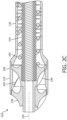
- FIG. 1 there is shown an exemplary embodiment of the atherectomy systems described here.
- the atherectomy system 100 includes an intravascular atherectomy device 102 and a guide wire 104 over which the atherectomy device 102 may be deployed.
- the guide wire 104 is silicon-coated or non-coated (bare), or otherwise free of a PTFE coating.
- Atherectomy systems according to some embodiments of the present disclosure comprise a guide wire that includes a PTFE coating, or atherectomy systems according to some embodiments of the present disclosure lack a guide wire.
- the atherectomy device 102 generally includes a handle 106 and a catheter 108.
- the handle 106 is configured to be grasped and manipulated by a user (for example, a medical professional) during an atherectomy procedure.
- the catheter 108 is coupled to and extends distally relative to the handle 106.
- the catheter 108 is configured to be positioned in the vasculature of a subject (for example, a patient) during an atherectomy procedure to facilitate removal of plaque therefrom.
- the catheter 108 is selectively rotatable about a catheter rotation axis 110 relative to the handle 106 to facilitate appropriately positioning and or "sweeping" a distal portion 112 of the catheter 108 during an atherectomy procedure.
- the handle 106 carries a rotatable knob or dial 114 for selectively rotating the catheter 108 relative to the handle 106.
- the catheter 108 includes an outer sheath 116 having a proximal portion 118 and a distal portion 120.
- the proximal portion 118 is coupled to and extends distally relative to the handle 106.
- the proximal portion 118 is an elongated component and defines a longitudinal axis 122 of the catheter 108.
- the longitudinal axis 122 is collinear with a catheter rotation axis 110.
- the longitudinal axis 122 is non-collinear with a catheter rotation axis 110.
- the distal portion 120 mechanically couples to the proximal portion 118 (for example, via welding or the like).
- the distal portion 120 integrally couples to, or is monolithically formed with, the proximal portion 118.
- the distal portion 120 extends distally relative to the proximal portion 118 and, as described in further detail below, normally has a curved configuration and is offset from the longitudinal axis 122.
- the catheter 108 further includes a cutter assembly 124 that is coupled to and extends distally relative to the distal portion 120 of the outer sheath 116.
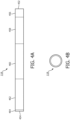
- FIGS. 2A-2C illustrate the distal portion 112 of the catheter 108.
- the distal portion 120 of the outer sheath 116 is pre-shaped in a curved configuration or normally has a curved configuration ("normally” being understood as the catheter 108 not being subjected to any external contact forces due to, for example, contact with blood vessel walls) and is offset from the longitudinal axis 122.
- the curved configuration of the distal portion 120 includes a double curve having a first, or proximal curve 226 and a second, or distal, curve 228.
- the proximal curve 226 bends or faces away from the longitudinal axis 122 and the distal curve 228 bends or faces toward the longitudinal axis 122.
- the curved configuration causes a rotation axis 230 of the cutter assembly 124 to be disposed at an acute angle 232 relative to the longitudinal axis 122 (for example, about 45 degrees, although other angles may alternatively be used, such as greater than zero and less than 50 degrees, more particularly about 5 degrees, 10 degrees, 15 degrees, 20 degrees, 25 degrees, 30 degrees, 35 degrees, 40 degrees, 50 degrees, 55 degrees, 60 degrees, 65 degrees, 70 degrees, 75 degrees, 80 degrees, 85 degrees, or 90 degrees) (as used herein regarding angles, the term "about” being understood as the specified angle ⁇ 10 percent).
- such dispositions of the cutter rotation axis 230 relative to the longitudinal axis 122 permit the cutter assembly 124 to oppose (that is, at least partially face toward) a blood vessel wall. Accordingly, the cutter assembly 124 can treat relatively large areas of plaque and provide relatively high luminal gain upon rotating the catheter 108 about the catheter rotation axis 110. Further, in some embodiments and situations, the double curve provides the catheter 108 with three contact points against the vasculature of the subject. More specifically, the proximal curve 226, the distal curve 228, and the cutter assembly 124 may each contact the vasculature of the subject.
- the outer sheath 116 carries a rotatable drive shaft 234 that couples the cutter assembly 124 to a prime mover (for example, a motor carried by the handle 106 - not shown). More specifically, the prime mover may rotate the drive shaft 234, which may in turn rotate a cutter 236 of the cutter assembly 124 with a cutter housing 238 of the cutter assembly 124 and about the cutter rotation axis 230.
- a prime mover for example, a motor carried by the handle 106 - not shown.
- the prime mover may rotate the drive shaft 234, which may in turn rotate a cutter 236 of the cutter assembly 124 with a cutter housing 238 of the cutter assembly 124 and about the cutter rotation axis 230.
- Rotation of the cutter 236 of causes one or more cutter elements 240 (for example, blades) to cut occlusive material and convey the occlusive material into the cutter housing 238 (a process also referred to as "debulking").
- the drive shaft 234 also translatably fixes the cutter 236 relative to the outer sheath 116.
- the cutter assembly 124 captures the cut occlusive material from the blood without the use of vacuum aspiration. In other embodiments, vacuum aspiration may assist capture of the cut occlusive material.
- the atherectomy device 102 also includes an internal conveyor 242 that is coupled to and rotates with the drive shaft 234. As occlusive material is conveyed into the cutter housing 238 by the cutter 236, the conveyor 242 displaces the cut occlusive material proximally through the catheter 108 for discharge outside the subject's body. In some embodiments, this conveyance may occur without the use of vacuum aspiration assistance. In other embodiments, vacuum aspiration may assist conveyance of the cut occlusive material.
- FIGS. 3A-3B illustrate the distal portion 120 of the outer sheath 116 of the catheter 108.
- the distal portion 120 of the outer sheath 116 is illustrated in its normal curved configuration
- the distal portion 120 of the outer sheath 116 is illustrated in a deflected configuration.
- the distal portion 120 comprises one or more materials that are appropriate for being disposed within the vasculature of a subject, such as electropolished nitinol or polyether ether ketone (PEEK).
- PEEK polyether ether ketone
- such materials and others may be set in, or urged to normally occupy, a curved configuration by constraining them in the curved configuration and applying thermal and/or electrical energy.
- the distal portion 120 has an outer diameter of about 0.067 inches (that is, 0.067 inches ⁇ 0.0008 inches) [about 1.7 mm (that is, 1.7 mm ⁇ 0.02 mm)] and an inner diameter of about 0.059 inches (that is, 0.059 inches ⁇ 0.0008 inches) [about 1.5 mm (that is, 1.5 mm ⁇ 0.02 mm)].
- the distal portion 120 of the outer sheath 116 has a length (that is, a distance between a proximal end 344 and a distal end 346, or a distance along the longitudinal axis 122 of the catheter 108) of about 1.549 inches (that is, 1.549 inches ⁇ 0.0008 inches) [about 39.34 mm (that is, 39.34 mm ⁇ 0.02 mm)]. In some embodiments and as illustrated in FIG.
- the distal portion 120 of the outer sheath 116 has an offset dimension or a span (that is, a distance between the proximal end 344 and the distal end 346 and the second curve 228, or a distance perpendicular to the longitudinal axis 122 of the catheter 108) of about 0.395 inches (that is, 0.395 inches ⁇ 0.020 inches) [about 10.03 mm (that is, 10.03 mm ⁇ 0.51 mm)].
- the distal portion 120 includes a distal section 347, an intermediate section 349 (which defines the second curve 228 described above), and a proximal section 351 (which defines the first curve 226 described above).
- the distal section 347, the intermediate section 349, and the proximal section 351 may have about the dimensions shown in Table 1 (angles are relative to the longitudinal axis 122 of the catheter 108, distances are projected onto the longitudinal axis 122 of the catheter 108 - "about” being understood as the specified dimension ⁇ 10 percent, and the term “substantially” being understood as the specified dimension ⁇ percent).
- Table 1 Section Angle (degrees) Distance (in. [mm]) Radius (in. [mm]) Distal (347) 45 0.18 [4.6] -- Intermediate (349) -- 0.54 [14] 0.48 [12] Proximal (351) -- 1.23 [31.2] 0.81 [21]
- the distal portion 120 of the outer sheath 116 may be relatively stiff to permit the catheter 108 to remove plaque from the vasculature in a curved configuration of the distal portion 120, and the distal portion 120 may be sufficiently flexible to deflect (for example and as shown in FIG. 3B , to a relatively straight configuration) while navigating the vasculature of a subject.
- the distal portion 120 includes a plurality of slits or kerfs 348 (that is, absences of material) that each extend through the wall of the distal portion 120.
- Such kerfs 348 may be provided by, for example, laser cutting processes.
- the distal portion 120 includes first pattern of alternating kerfs 348 and non-slit or non-kerf portions 350 (that is, portions of the distal portion 120 include material and lacking kerfs 348) over its length.
- the pattern of alternating kerfs 348 and non-kerf portions 350 may include, at each axial position within the pattern, a first kerf 348 having a longitudinal width of about 0.0015 inches [0.04 mm] and a circumferential length of about 90 degrees, a first non-kerf portion 350 having a circumferential length of about 30 degrees, a second kerf 348 having a longitudinal width of about 0.0015 inches [0.04 mm] and a circumferential length of about 90 degrees, a second non-kerf portion 350 having a circumferential length of about 30 degrees, a third kerf 348 having a longitudinal width of about 0.0015 inches [0.04 mm] and a circumferential length of about 90 degrees, and a third non-kerf portion 350 having
- Sets of kerfs 348 and non-kerf portions 350 in each axial position may be offset from sets of kerfs 348 and non-kerf portions 350 at one or more adjacent axial positions by (that is, the pattern may have a pitch of) about 0.012 inches [0.03 mm].
- the pitch may be constant along the length of the outer sheath 116. In other embodiments, the pitch may be variable.
- the kerfs 348 may be perpendicular to the longitudinal axis (that is, the pattern may have a pitch angle of zero degrees). In other embodiments, the kerfs 348 may be non-perpendicular to the longitudinal axis (that is, the pattern may have a non-zero pitch angle). In some embodiments, the pattern may have a variable pitch angle.
- FIGS. 4A-4B illustrate the proximal portion 118 of the outer sheath 116 of the catheter 108.
- the proximal portion 118 comprises one or more materials that are appropriate for being disposed within the vasculature of a subject, such as tempered stainless steel.
- the proximal portion 118 has an outer diameter of about 0.061 inches (that is, 0.061 inches ⁇ 0.0005 inches) [about 1.5 mm (that is, 1.5 mm ⁇ 0.01 mm)] and an inner diameter of about 0.052 inches (that is, 0.052 inches ⁇ 0.0005 inches) [about 1.3 mm (that is, 1.3 mm ⁇ 0.01 mm)].
- the proximal portion 118 of the outer sheath 116 includes several sections having different flexibility characteristics.
- the proximal portion 118 is relatively stiff near its proximal end 452 to facilitate pushability of the catheter 108
- the proximal portion 118 is relatively flexible near its distal end 454 to facilitate navigating the vasculature of a subject.
- the proximal portion 118 includes a relatively stiff proximal end section 456.
- the proximal end section 456 lacks slits or kerfs.
- the proximal end section 456 may have a length of about 4.0 inches (that is, 4.0 inches ⁇ 0.03 inches) [about 102 mm (that is, 102 mm ⁇ 0.8 mm)].
- the proximal portion 118 also includes a first intermediate section 458 that extends distally relative to the proximal end section 456.
- the first intermediate section 458 may have a length of about 9.9 inches (that is, 9.9 inches ⁇ 0.03 inches) [about 251 mm (that is, 251 mm ⁇ 0.8 mm)].
- the first intermediate section 458 may be relatively stiff compared to other sections. More specifically, the first intermediate section 458 may include a second pattern of kerfs and non-kerf portions (not shown) over its length.
- the pattern of alternating kerfs and non-kerf portions may include, at each axial position within the pattern, a first kerf having a longitudinal width of about 0.002 inches [about 0.05 mm] and a circumferential length of about 75 degrees, a first non-kerf portion having a circumferential length of about 15 degrees, a second kerf having a longitudinal width of about 0.002 inches [about 0.05 mm] and a circumferential length of about 75 degrees, a second non-kerf portion having a circumferential length of about 15 degrees, a third kerf having a longitudinal width of about 0.002 inches [about 0.05 mm] and a circumferential length of about 75 degrees, a third non-kerf portion having a circumferential length of about 15 degrees, a fourth kerf having a longitudinal width of about 0.002 inches [about 0.05 mm] and a circumferential length of about 75 degrees, and a fourth non-kerf portion having a circumferential length of about 15 degrees.
- Sets of kerfs and non-kerf portions in each axial position may be offset from sets of kerfs and non-kerfs portions at one or more adjacent axial positions by (that is, the pattern may have a pitch of) about 0.014 inches (that is, 0.014 inches ⁇ 0.002 inches) [about 0.36 mm (that is, 0.36 mm ⁇ 0.05 mm)].
- the pitch may be constant or variable.
- the kerfs may be perpendicular to the longitudinal axis or non-perpendicular to the longitudinal axis.
- the pattern may have a variable pitch angle.
- the proximal portion 118 also includes a second intermediate section 460 that extends distally relative to the first intermediate section 458.
- the second intermediate section 460 may have a length of about 25.0 inches (that is, 25.0 inches ⁇ 0.03 inches) [about 635 mm (that is, 635 mm ⁇ 0.8 mm)].
- the second intermediate section 460 may be relatively flexible compared to the first intermediate section 458. More specifically, the second intermediate section 460 may include a third pattern of kerfs and non-kerf portions (not shown) over its length.
- the pattern of alternating kerfs and non-kerf portions may include, at each axial position within the pattern, a first kerf having a longitudinal width of about 0.002 inches [about 0.05 mm] and a circumferential length of about 75 degrees, a first non-kerf portion having a circumferential length of about 15 degrees, a second kerf having a longitudinal width of about 0.002 inches [about 0.05 mm] and a circumferential length of about 75 degrees, a second non-kerf portion having a circumferential length of about 15 degrees, a third kerf having a longitudinal width of about 0.002 inches [about 0.05 mm] and a circumferential length of about 75 degrees, a third non-kerf portion having a circumferential length of about 15 degrees, a fourth kerf having a longitudinal width of about 0.002 inches [about 0.05 mm] and a circumferential length of about 75 degrees, and a fourth non-kerf portion having a circumferential length of about 15 degrees.
- Sets of kerfs and non-kerf portions in each axial position may be offset from sets of kerfs and non-kerfs portions at one or more adjacent axial positions by (that is, the pattern may have a pitch of) about 0.012 inches (that is, 0.012 inches ⁇ 0.002 inches) [about 0.30 mm (that is, 0.30 mm ⁇ 0.05 mm)].
- the pitch may be constant or variable.
- the kerfs may be perpendicular to the longitudinal axis or non-perpendicular to the longitudinal axis.
- the pattern may have a variable pitch angle.
- the proximal portion 118 also includes a third intermediate section 462 that extends distally relative to the second intermediate section 460.
- the third intermediate section 462 may have a length of about 16.0 inches (that is, 16.0 inches ⁇ 0.03 inches) [about 406 mm (that is, 406 mm ⁇ 0.8 mm)].
- the third intermediate section 462 may be relatively flexible compared to the second intermediate section 460. More specifically, the third intermediate section 462 may include a fourth pattern of kerfs and non-kerf portions (not shown) over its length.
- the pattern of alternating kerfs and non-kerf portions may include, at each axial position within the pattern, a first kerf having a longitudinal width of about 0.002 inches [about 0.05 mm] and a circumferential length of about 75 degrees, a first non-kerf portion having a circumferential length of about 15 degrees, a second kerf having a longitudinal width of about 0.002 inches [about 0.05 mm] and a circumferential length of about 75 degrees, a second non-kerf portion having a circumferential length of about 15 degrees, a third kerf having a longitudinal width of about 0.002 inches [about 0.05 mm] and a circumferential length of about 75 degrees, a third non-kerf portion having a circumferential length of about 15 degrees, a fourth kerf having a longitudinal width of about
- Sets of kerfs and non-kerf portions in each axial position may be offset from sets of kerfs and non-kerfs portions at one or more adjacent axial positions by (that is, the pattern may have a pitch of) about 0.011 inches (that is, 0.011 inches ⁇ 0.002 inches) [about 0.28 mm (that is, 0.28 mm ⁇ 0.05 mm)].
- the pitch may be constant or variable.
- the kerfs may be perpendicular to the longitudinal axis or non-perpendicular to the longitudinal axis.
- the pattern may have a variable pitch angle.
- the proximal portion 118 further includes a relatively stiff distal end section 464.
- the distal end section 464 lacks slits or kerfs.
- the distal end section 464 may have a length of about 0.030 inches (that is, 0.030 inches ⁇ 0.002 inches) [about 0.76 mm (that is, 0.76 mm ⁇ 0.05 mm)].
- the atherectomy system 100 lacks any components for actively deflecting or reconfiguring the catheter 108 (for example, pull wires for deflecting or reconfiguring the catheter 108).
- the catheter 108 is only passively deflected or reconfigured (that is, reconfiguration or defection caused by external contact forces due to, for example, extending through an introducer sheath and/or contact with blood vessel walls).
- the lack of components for actively deflecting or reconfiguring the catheter 108 permits the catheter 108 to have a relatively small overall size, such as 6-French.
- the catheter 108 may have other overall sizes, such as 7-French, 8-French. 9-French, or the like.
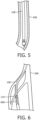
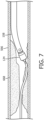
- FIGS. 5-7 illustrate the catheter 108 navigating the vasculature 566 of a subject and removing plaque.
- FIG. 5 illustrates the catheter 108 being passively deflected to a relatively straight configuration while navigating the vasculature 566.
- the catheter 108 may be passively deflected or reconfigured by extending through an introducer sheath and/or contacting blood vessel walls.
- FIG. 6 illustrates the catheter 108 occupying a curved configuration and the cutter assembly 124 being disposed near plaque 668 within the vasculature 566.
- FIG. 7 illustrates the catheter 108 occupying a curved configuration and the cutter assembly 124 removing plaque 668 from the vasculature 566.
- the catheter 108 may be rotated about the catheter rotation axis 110 (or "swept") to further remove plaque 668 and provide relatively high luminal gain.
- the distal portion 120 of the outer sheath 116 of the catheter 108 when the distal portion 120 of the outer sheath 116 of the catheter 108 is inserted within a lumen of an introducer sheath, passing through the lumen of the introducer sheath, and/or exiting the introducer sheath, the distal portion 120 and/or the cutter assembly 124 is designed to contact the inner wall of the introducer sheath. That is, the distal portion 120 of the outer sheath 116 is pre-shaped in a curved configuration or normally has a curved configuration to ensure that the distal portion 120 and/or the cutter assembly 124 always contacts the inner wall of the introducer sheath as the distal portion 120 and/or the cutter assembly 124 pass through the lumen formed within the introducer sheath. Similarly, as the distal portion 120 and/or the cutter assembly 124 exits the introducer sheath, the distal portion 120 and/or the cutter assembly 124 contacts vasculature 566 and/or the plaque 668.
Landscapes
- Health & Medical Sciences (AREA)
- Surgery (AREA)
- Life Sciences & Earth Sciences (AREA)
- Medical Informatics (AREA)
- Nuclear Medicine, Radiotherapy & Molecular Imaging (AREA)
- Engineering & Computer Science (AREA)
- Biomedical Technology (AREA)
- Heart & Thoracic Surgery (AREA)
- Vascular Medicine (AREA)
- Molecular Biology (AREA)
- Animal Behavior & Ethology (AREA)
- General Health & Medical Sciences (AREA)
- Public Health (AREA)
- Veterinary Medicine (AREA)
- Surgical Instruments (AREA)
- Media Introduction/Drainage Providing Device (AREA)
Claims (9)
- Atherektomievorrichtung (102), umfassend:einen Griff (106), der konfiguriert ist, um von einem Benutzer gehandhabt zu werden;einen Katheter, umfassend:eine äußere Hülle (116), umfassend:einen proximalen Abschnitt (118), der an den Griff (106) gekoppelt ist und sich in Bezug dazu distal erstreckt, wobei der proximale Abschnitt (118) eine Längsachse des Katheters definiert;einen distalen Abschnitt (120), der an den proximalen Abschnitt (118) gekoppelt ist und sich in Bezug dazu distal erstreckt, wobei der distale Abschnitt (120) normalerweise eine gekrümmte Konfiguration aufweist und von der Längsachse (122) versetzt ist, und wobei der distale Abschnitt (120) ein Muster aus Abschnitten mit Schlitzen und ohne Schlitze oder ein Muster aus Abschnitten mit Kerben und ohne Kerben umfasst;eine Antriebswelle, die innerhalb der äußeren Hülle (116) getragen wird und in Bezug dazu drehbar ist; undeine Schneideranordnung (124), die an den distalen Abschnitt (120) der äußeren Hülle (116) gekoppelt ist und sich in Bezug dazu distal erstreckt, wobei die Schneideranordnung (124) einen Schneider beinhaltet, der in Bezug zur äußeren Hülle (116) verschiebbar befestigt ist, wobei der Schneider an die Antriebswelle gekoppelt ist und sich bei Drehung der Antriebswelle in Bezug zur äußeren Hülle (116) um eine Schneiderdrehachse dreht, wobei die Schneiderdrehachse normalerweise in einem spitzen Winkel (232) in Bezug zur Längsachse (122) angeordnet ist;wobei die gekrümmte Konfiguration eine proximale Krümmung (226) und eine distale Krümmung (228) umfasst; undwobei sich die proximale Krümmung (226) von der Längsachse (122) weg biegt und die distale Krümmung (228) sich zur Längsachse (122) hin biegt.
- Atherektomievorrichtung (102) nach Anspruch 1, wobei der Katheter in Bezug zum Griff (106) um eine Katheterdrehachse drehbar ist.
- Atherektomievorrichtung (102) nach Anspruch 2, wobei die Katheterdrehachse kollinear mit der Längsachse (122) ist.
- Atherektomievorrichtung (102) nach Anspruch 1, wobei der distale Abschnitt (120) einen proximalen Teilabschnitt (351) umfasst, der sich von der Längsachse (122) weg biegt, einen mittleren Teilabschnitt (462), der distal von dem proximalen Teilabschnitt (351) angeordnet ist und sich in Richtung der Längsachse (122) biegt, und einen distalen Teilabschnitt (347), der distal von dem mittleren Teilabschnitt (462) angeordnet ist, wobei sich der distale Teilabschnitt (347) linear erstreckt und in einem spitzen Winkel in Bezug zur Längsachse (122) angeordnet ist.
- Atherektomievorrichtung (102) nach Anspruch 4, wobei der proximale Teilabschnitt (351) die proximale Krümmung (226) definiert und die proximale Krümmung (226) einen Radius von 0,81 Zoll ± 10 % aufweist, was 21 mm ± 10% entspricht, und eine auf die Längsachse (122) projizierte Länge von 31,2 Millimeter ± 10%.
- Atherektomievorrichtung (102) nach Anspruch 4, wobei der mittlere Teilabschnitt (462) die distale Krümmung (228) definiert und die distale Krümmung (228) einen Radius von 0,48 Zoll ± 10% aufweist, was 12 mm ± 10% entspricht, und eine auf die Längsachse (122) projizierte Länge von 14 Millimeter ± 10%.
- Atherektomievorrichtung (102) nach Anspruch 4, wobei der distale Teilabschnitt (347) eine auf die Längsachse (122) projizierte Länge von 4,6 Millimetern ± 10% aufweist.
- Atherektomievorrichtung (102) nach Anspruch 1, wobei das Muster ein erstes Muster ist und wobei der proximale Abschnitt (118) ein zweites Muster umfasst, das ein Muster aus Abschnitten mit Schlitzen und ohne Schlitze oder ein Muster aus Abschnitten mit Kerben und ohne Kerben ist, wobei sich das zweite Muster von dem ersten Muster unterscheidet.
- Atherektomievorrichtung (102) nach Anspruch 1, wobei der spitze Winkel (232) 45 Grad ± 10% beträgt.
Applications Claiming Priority (2)
| Application Number | Priority Date | Filing Date | Title |
|---|---|---|---|
| US201862754228P | 2018-11-01 | 2018-11-01 | |
| PCT/EP2019/079876 WO2020089415A1 (en) | 2018-11-01 | 2019-10-31 | Atherectomy devices including pre-shaped and curved distal portions and methods |
Publications (2)
| Publication Number | Publication Date |
|---|---|
| EP3873360A1 EP3873360A1 (de) | 2021-09-08 |
| EP3873360B1 true EP3873360B1 (de) | 2025-03-19 |
Family
ID=68501586
Family Applications (1)
| Application Number | Title | Priority Date | Filing Date |
|---|---|---|---|
| EP19800953.2A Active EP3873360B1 (de) | 2018-11-01 | 2019-10-31 | Atherektomievorrichtungen mit vorgeformten und gekrümmten distalen abschnitten |
Country Status (5)
| Country | Link |
|---|---|
| US (1) | US20210386451A1 (de) |
| EP (1) | EP3873360B1 (de) |
| JP (1) | JP7486481B2 (de) |
| CN (1) | CN113271877A (de) |
| WO (1) | WO2020089415A1 (de) |
Families Citing this family (12)
| Publication number | Priority date | Publication date | Assignee | Title |
|---|---|---|---|---|
| JP2022510654A (ja) | 2018-11-28 | 2022-01-27 | ヒストソニックス,インコーポレーテッド | 組織破砕システムおよび方法 |
| CA3169465A1 (en) | 2020-01-28 | 2021-08-05 | The Regents Of The University Of Michigan | Systems and methods for histotripsy immunosensitization |
| BR112022025722A2 (pt) | 2020-06-18 | 2023-03-07 | Histosonics Inc | Sistemas e métodos de acoplamento acústico e paciente de histotripsia |
| CA3190517A1 (en) | 2020-08-27 | 2022-03-03 | Timothy Lewis HALL | Ultrasound transducer with transmit-receive capability for histotripsy |
| CN113017780B (zh) * | 2021-03-02 | 2022-03-08 | 哈尔滨医科大学 | 一种集成超声成像与腔内斑块旋切术的导管系统 |
| WO2022260746A1 (en) | 2021-06-07 | 2022-12-15 | The Regents Of The University Of Michigan | Minimally invasive histotripsy systems and methods |
| IL308943A (en) | 2021-06-07 | 2024-01-01 | Univ Michigan Regents | All-inclusive ultrasound systems and methods that include histotripsy |
| KR102621677B1 (ko) * | 2021-08-27 | 2024-01-04 | 한림대학교 산학협력단 | 회전 가능한 내시경적 역행성 담췌관조영술 절개도 |
| WO2023193895A1 (en) | 2022-04-06 | 2023-10-12 | Clearstream Technologies Limited | A control handle for an atherectomy device |
| EP4608504A1 (de) | 2022-10-28 | 2025-09-03 | Histosonics, Inc. | Histotripsiesysteme und -verfahren |
| KR20260003742A (ko) | 2023-04-20 | 2026-01-07 | 히스토소닉스, 인크. | 치료 계획 및 요법을 위한 사용자 인터페이스들 및 작업 흐름들을 포함하는 히스토트립시 시스템들 및 연관된 방법들 |
| CN119606493B (zh) * | 2023-09-14 | 2025-09-19 | 杭州德晋医疗科技有限公司 | 便于定位的房间隔穿刺系统 |
Citations (1)
| Publication number | Priority date | Publication date | Assignee | Title |
|---|---|---|---|---|
| US20130103062A1 (en) * | 2006-06-30 | 2013-04-25 | Atheromed, Inc. | Atherectomy devices and methods |
Family Cites Families (15)
| Publication number | Priority date | Publication date | Assignee | Title |
|---|---|---|---|---|
| US6497711B1 (en) * | 2000-08-16 | 2002-12-24 | Scimed Life Systems, Inc. | Therectomy device having a light weight drive shaft and an imaging device |
| US20050209610A1 (en) * | 2004-03-03 | 2005-09-22 | Scimed Life Systems, Inc. | Radially adjustable tissue removal device |
| US7621904B2 (en) * | 2004-10-21 | 2009-11-24 | Boston Scientific Scimed, Inc. | Catheter with a pre-shaped distal tip |
| EP2037821B1 (de) * | 2006-06-30 | 2022-06-22 | Atheromed, Inc. | Atherektomievorrichtungen |
| WO2009005779A1 (en) | 2007-06-29 | 2009-01-08 | Atheromed, Inc. | Atherectomy devices, systems, and methods |
| JP5253842B2 (ja) | 2008-02-29 | 2013-07-31 | ジョンソン・エンド・ジョンソン株式会社 | 吸引カテーテル |
| JP5688160B2 (ja) * | 2010-11-11 | 2015-03-25 | コヴィディエン リミテッド パートナーシップ | 撮像を伴う可撓性減量カテーテル、および、その使用および製造方法 |
| US9949754B2 (en) | 2011-03-28 | 2018-04-24 | Avinger, Inc. | Occlusion-crossing devices |
| US9345511B2 (en) * | 2011-10-13 | 2016-05-24 | Atheromed, Inc. | Atherectomy apparatus, systems and methods |
| US20150359595A1 (en) * | 2013-01-31 | 2015-12-17 | Eximo Medical Ltd. | Hybrid catheter apparatus and methods |
| MX2016010141A (es) * | 2014-02-06 | 2017-04-06 | Avinger Inc | Cateteres de aterectomia y dispositivos de cruce de oclusion. |
| WO2016132241A1 (en) | 2015-02-20 | 2016-08-25 | Koninklijke Philips N.V. | Atherectomy apparatus with imaging |
| US10206706B2 (en) * | 2015-05-29 | 2019-02-19 | Medtronic Xomed, Inc. | Inner tubular member for angled rotary surgical instrument |
| US11382654B2 (en) * | 2016-02-25 | 2022-07-12 | Indian Wells Medical, Inc. | Steerable endoluminal punch with cutting stylet |
| WO2018221461A1 (en) * | 2017-05-30 | 2018-12-06 | Terumo Kabushiki Kaisha | Atherectomy device and method |
-
2019
- 2019-10-31 JP JP2021523651A patent/JP7486481B2/ja active Active
- 2019-10-31 WO PCT/EP2019/079876 patent/WO2020089415A1/en not_active Ceased
- 2019-10-31 US US17/289,273 patent/US20210386451A1/en active Pending
- 2019-10-31 EP EP19800953.2A patent/EP3873360B1/de active Active
- 2019-10-31 CN CN201980079517.5A patent/CN113271877A/zh active Pending
Patent Citations (1)
| Publication number | Priority date | Publication date | Assignee | Title |
|---|---|---|---|---|
| US20130103062A1 (en) * | 2006-06-30 | 2013-04-25 | Atheromed, Inc. | Atherectomy devices and methods |
Also Published As
| Publication number | Publication date |
|---|---|
| CN113271877A (zh) | 2021-08-17 |
| US20210386451A1 (en) | 2021-12-16 |
| EP3873360A1 (de) | 2021-09-08 |
| JP7486481B2 (ja) | 2024-05-17 |
| WO2020089415A1 (en) | 2020-05-07 |
| JP2022508043A (ja) | 2022-01-19 |
Similar Documents
| Publication | Publication Date | Title |
|---|---|---|
| EP3873360B1 (de) | Atherektomievorrichtungen mit vorgeformten und gekrümmten distalen abschnitten | |
| EP3986296B1 (de) | Atherektomiegeräte, einschliesslich einer pluralität von distalen schneidfunktionen | |
| EP4017383B1 (de) | Atherektomiegeräte mit schneidklingen mit unterschiedlichen kantenformen | |
| CN114423362B (zh) | 包括轴向地摆动的切割元件的斑块切除装置 | |
| US20240382230A1 (en) | Abrasive elements for rotational atherectomy systems | |
| EP3968876B1 (de) | Atherektomie-vorrichtungen mit positiven und negativen spanwinkelschneidklingen | |
| EP4076229B1 (de) | Atherektomievorrichtungen mit abgedichteten antriebswellen | |
| CN115461000B (zh) | 包括密封的驱动轴的斑块切除装置 |
Legal Events
| Date | Code | Title | Description |
|---|---|---|---|
| STAA | Information on the status of an ep patent application or granted ep patent |
Free format text: STATUS: UNKNOWN |
|
| STAA | Information on the status of an ep patent application or granted ep patent |
Free format text: STATUS: THE INTERNATIONAL PUBLICATION HAS BEEN MADE |
|
| PUAI | Public reference made under article 153(3) epc to a published international application that has entered the european phase |
Free format text: ORIGINAL CODE: 0009012 |
|
| STAA | Information on the status of an ep patent application or granted ep patent |
Free format text: STATUS: REQUEST FOR EXAMINATION WAS MADE |
|
| 17P | Request for examination filed |
Effective date: 20210601 |
|
| AK | Designated contracting states |
Kind code of ref document: A1 Designated state(s): AL AT BE BG CH CY CZ DE DK EE ES FI FR GB GR HR HU IE IS IT LI LT LU LV MC MK MT NL NO PL PT RO RS SE SI SK SM TR |
|
| DAV | Request for validation of the european patent (deleted) | ||
| DAX | Request for extension of the european patent (deleted) | ||
| STAA | Information on the status of an ep patent application or granted ep patent |
Free format text: STATUS: EXAMINATION IS IN PROGRESS |
|
| 17Q | First examination report despatched |
Effective date: 20230703 |
|
| GRAP | Despatch of communication of intention to grant a patent |
Free format text: ORIGINAL CODE: EPIDOSNIGR1 |
|
| STAA | Information on the status of an ep patent application or granted ep patent |
Free format text: STATUS: GRANT OF PATENT IS INTENDED |
|
| INTG | Intention to grant announced |
Effective date: 20241022 |
|
| GRAS | Grant fee paid |
Free format text: ORIGINAL CODE: EPIDOSNIGR3 |
|
| GRAA | (expected) grant |
Free format text: ORIGINAL CODE: 0009210 |
|
| STAA | Information on the status of an ep patent application or granted ep patent |
Free format text: STATUS: THE PATENT HAS BEEN GRANTED |
|
| AK | Designated contracting states |
Kind code of ref document: B1 Designated state(s): AL AT BE BG CH CY CZ DE DK EE ES FI FR GB GR HR HU IE IS IT LI LT LU LV MC MK MT NL NO PL PT RO RS SE SI SK SM TR |
|
| REG | Reference to a national code |
Ref country code: GB Ref legal event code: FG4D |
|
| REG | Reference to a national code |
Ref country code: CH Ref legal event code: EP |
|
| REG | Reference to a national code |
Ref country code: DE Ref legal event code: R096 Ref document number: 602019067528 Country of ref document: DE |
|
| REG | Reference to a national code |
Ref country code: IE Ref legal event code: FG4D |
|
| PG25 | Lapsed in a contracting state [announced via postgrant information from national office to epo] |
Ref country code: RS Free format text: LAPSE BECAUSE OF FAILURE TO SUBMIT A TRANSLATION OF THE DESCRIPTION OR TO PAY THE FEE WITHIN THE PRESCRIBED TIME-LIMIT Effective date: 20250619 |
|
| PG25 | Lapsed in a contracting state [announced via postgrant information from national office to epo] |
Ref country code: FI Free format text: LAPSE BECAUSE OF FAILURE TO SUBMIT A TRANSLATION OF THE DESCRIPTION OR TO PAY THE FEE WITHIN THE PRESCRIBED TIME-LIMIT Effective date: 20250319 |
|
| REG | Reference to a national code |
Ref country code: LT Ref legal event code: MG9D |
|
| PG25 | Lapsed in a contracting state [announced via postgrant information from national office to epo] |
Ref country code: NO Free format text: LAPSE BECAUSE OF FAILURE TO SUBMIT A TRANSLATION OF THE DESCRIPTION OR TO PAY THE FEE WITHIN THE PRESCRIBED TIME-LIMIT Effective date: 20250619 |
|
| PG25 | Lapsed in a contracting state [announced via postgrant information from national office to epo] |
Ref country code: HR Free format text: LAPSE BECAUSE OF FAILURE TO SUBMIT A TRANSLATION OF THE DESCRIPTION OR TO PAY THE FEE WITHIN THE PRESCRIBED TIME-LIMIT Effective date: 20250319 |
|
| PG25 | Lapsed in a contracting state [announced via postgrant information from national office to epo] |
Ref country code: LV Free format text: LAPSE BECAUSE OF FAILURE TO SUBMIT A TRANSLATION OF THE DESCRIPTION OR TO PAY THE FEE WITHIN THE PRESCRIBED TIME-LIMIT Effective date: 20250319 |
|
| PG25 | Lapsed in a contracting state [announced via postgrant information from national office to epo] |
Ref country code: GR Free format text: LAPSE BECAUSE OF FAILURE TO SUBMIT A TRANSLATION OF THE DESCRIPTION OR TO PAY THE FEE WITHIN THE PRESCRIBED TIME-LIMIT Effective date: 20250620 Ref country code: BG Free format text: LAPSE BECAUSE OF FAILURE TO SUBMIT A TRANSLATION OF THE DESCRIPTION OR TO PAY THE FEE WITHIN THE PRESCRIBED TIME-LIMIT Effective date: 20250319 |
|
| REG | Reference to a national code |
Ref country code: NL Ref legal event code: MP Effective date: 20250319 |
|
| REG | Reference to a national code |
Ref country code: AT Ref legal event code: MK05 Ref document number: 1776293 Country of ref document: AT Kind code of ref document: T Effective date: 20250319 |
|
| PG25 | Lapsed in a contracting state [announced via postgrant information from national office to epo] |
Ref country code: NL Free format text: LAPSE BECAUSE OF FAILURE TO SUBMIT A TRANSLATION OF THE DESCRIPTION OR TO PAY THE FEE WITHIN THE PRESCRIBED TIME-LIMIT Effective date: 20250319 |
|
| PG25 | Lapsed in a contracting state [announced via postgrant information from national office to epo] |
Ref country code: SE Free format text: LAPSE BECAUSE OF FAILURE TO SUBMIT A TRANSLATION OF THE DESCRIPTION OR TO PAY THE FEE WITHIN THE PRESCRIBED TIME-LIMIT Effective date: 20250319 |
|
| PG25 | Lapsed in a contracting state [announced via postgrant information from national office to epo] |
Ref country code: SM Free format text: LAPSE BECAUSE OF FAILURE TO SUBMIT A TRANSLATION OF THE DESCRIPTION OR TO PAY THE FEE WITHIN THE PRESCRIBED TIME-LIMIT Effective date: 20250319 |
|
| PG25 | Lapsed in a contracting state [announced via postgrant information from national office to epo] |
Ref country code: PT Free format text: LAPSE BECAUSE OF FAILURE TO SUBMIT A TRANSLATION OF THE DESCRIPTION OR TO PAY THE FEE WITHIN THE PRESCRIBED TIME-LIMIT Effective date: 20250721 Ref country code: ES Free format text: LAPSE BECAUSE OF FAILURE TO SUBMIT A TRANSLATION OF THE DESCRIPTION OR TO PAY THE FEE WITHIN THE PRESCRIBED TIME-LIMIT Effective date: 20250319 |
|
| PG25 | Lapsed in a contracting state [announced via postgrant information from national office to epo] |
Ref country code: IT Free format text: LAPSE BECAUSE OF FAILURE TO SUBMIT A TRANSLATION OF THE DESCRIPTION OR TO PAY THE FEE WITHIN THE PRESCRIBED TIME-LIMIT Effective date: 20250319 Ref country code: PL Free format text: LAPSE BECAUSE OF FAILURE TO SUBMIT A TRANSLATION OF THE DESCRIPTION OR TO PAY THE FEE WITHIN THE PRESCRIBED TIME-LIMIT Effective date: 20250319 |
|
| PG25 | Lapsed in a contracting state [announced via postgrant information from national office to epo] |
Ref country code: AT Free format text: LAPSE BECAUSE OF FAILURE TO SUBMIT A TRANSLATION OF THE DESCRIPTION OR TO PAY THE FEE WITHIN THE PRESCRIBED TIME-LIMIT Effective date: 20250319 |
|
| PG25 | Lapsed in a contracting state [announced via postgrant information from national office to epo] |
Ref country code: CZ Free format text: LAPSE BECAUSE OF FAILURE TO SUBMIT A TRANSLATION OF THE DESCRIPTION OR TO PAY THE FEE WITHIN THE PRESCRIBED TIME-LIMIT Effective date: 20250319 Ref country code: EE Free format text: LAPSE BECAUSE OF FAILURE TO SUBMIT A TRANSLATION OF THE DESCRIPTION OR TO PAY THE FEE WITHIN THE PRESCRIBED TIME-LIMIT Effective date: 20250319 |
|
| PG25 | Lapsed in a contracting state [announced via postgrant information from national office to epo] |
Ref country code: RO Free format text: LAPSE BECAUSE OF FAILURE TO SUBMIT A TRANSLATION OF THE DESCRIPTION OR TO PAY THE FEE WITHIN THE PRESCRIBED TIME-LIMIT Effective date: 20250319 |
|
| PG25 | Lapsed in a contracting state [announced via postgrant information from national office to epo] |
Ref country code: SK Free format text: LAPSE BECAUSE OF FAILURE TO SUBMIT A TRANSLATION OF THE DESCRIPTION OR TO PAY THE FEE WITHIN THE PRESCRIBED TIME-LIMIT Effective date: 20250319 |
|
| PG25 | Lapsed in a contracting state [announced via postgrant information from national office to epo] |
Ref country code: IS Free format text: LAPSE BECAUSE OF FAILURE TO SUBMIT A TRANSLATION OF THE DESCRIPTION OR TO PAY THE FEE WITHIN THE PRESCRIBED TIME-LIMIT Effective date: 20250719 |
|
| REG | Reference to a national code |
Ref country code: DE Ref legal event code: R097 Ref document number: 602019067528 Country of ref document: DE |
|
| PGFP | Annual fee paid to national office [announced via postgrant information from national office to epo] |
Ref country code: DE Payment date: 20251028 Year of fee payment: 7 |
|
| PGFP | Annual fee paid to national office [announced via postgrant information from national office to epo] |
Ref country code: GB Payment date: 20251023 Year of fee payment: 7 |
|
| PG25 | Lapsed in a contracting state [announced via postgrant information from national office to epo] |
Ref country code: DK Free format text: LAPSE BECAUSE OF FAILURE TO SUBMIT A TRANSLATION OF THE DESCRIPTION OR TO PAY THE FEE WITHIN THE PRESCRIBED TIME-LIMIT Effective date: 20250319 |
|
| PLBE | No opposition filed within time limit |
Free format text: ORIGINAL CODE: 0009261 |
|
| STAA | Information on the status of an ep patent application or granted ep patent |
Free format text: STATUS: NO OPPOSITION FILED WITHIN TIME LIMIT |
|
| REG | Reference to a national code |
Ref country code: CH Ref legal event code: L10 Free format text: ST27 STATUS EVENT CODE: U-0-0-L10-L00 (AS PROVIDED BY THE NATIONAL OFFICE) Effective date: 20260128 |
|
| 26N | No opposition filed |
Effective date: 20251222 |