EP3873202B1 - Vorrichtung mit anpassbarem mechanismus für erhöhten haustierfütterer - Google Patents
Vorrichtung mit anpassbarem mechanismus für erhöhten haustierfütterer Download PDFInfo
- Publication number
- EP3873202B1 EP3873202B1 EP19880306.6A EP19880306A EP3873202B1 EP 3873202 B1 EP3873202 B1 EP 3873202B1 EP 19880306 A EP19880306 A EP 19880306A EP 3873202 B1 EP3873202 B1 EP 3873202B1
- Authority
- EP
- European Patent Office
- Prior art keywords
- pet food
- supporting tray
- actuating mechanism
- telescoping
- food bowl
- Prior art date
- Legal status (The legal status is an assumption and is not a legal conclusion. Google has not performed a legal analysis and makes no representation as to the accuracy of the status listed.)
- Active
Links
Images















Classifications
-
- A—HUMAN NECESSITIES
- A01—AGRICULTURE; FORESTRY; ANIMAL HUSBANDRY; HUNTING; TRAPPING; FISHING
- A01K—ANIMAL HUSBANDRY; AVICULTURE; APICULTURE; PISCICULTURE; FISHING; REARING OR BREEDING ANIMALS, NOT OTHERWISE PROVIDED FOR; NEW BREEDS OF ANIMALS
- A01K5/00—Feeding devices for stock or game ; Feeding wagons; Feeding stacks
- A01K5/01—Feed troughs; Feed pails
- A01K5/0114—Pet food dispensers; Pet food trays
- A01K5/0135—Pet food dispensers; Pet food trays with means for preventing or catching spillage
-
- A—HUMAN NECESSITIES
- A01—AGRICULTURE; FORESTRY; ANIMAL HUSBANDRY; HUNTING; TRAPPING; FISHING
- A01K—ANIMAL HUSBANDRY; AVICULTURE; APICULTURE; PISCICULTURE; FISHING; REARING OR BREEDING ANIMALS, NOT OTHERWISE PROVIDED FOR; NEW BREEDS OF ANIMALS
- A01K5/00—Feeding devices for stock or game ; Feeding wagons; Feeding stacks
- A01K5/01—Feed troughs; Feed pails
- A01K5/0114—Pet food dispensers; Pet food trays
-
- A—HUMAN NECESSITIES
- A01—AGRICULTURE; FORESTRY; ANIMAL HUSBANDRY; HUNTING; TRAPPING; FISHING
- A01K—ANIMAL HUSBANDRY; AVICULTURE; APICULTURE; PISCICULTURE; FISHING; REARING OR BREEDING ANIMALS, NOT OTHERWISE PROVIDED FOR; NEW BREEDS OF ANIMALS
- A01K5/00—Feeding devices for stock or game ; Feeding wagons; Feeding stacks
- A01K5/02—Automatic devices
- A01K5/0291—Automatic devices with timing mechanisms, e.g. pet feeders
Definitions
- the present disclosure relates to pet food feeding devices.
- Pet food devices that automatically dispense food and water at a specified time are known in the art. Such devices remain at a particular elevation such as at the floor level or on a countertop, etc. and thus do not accommodate the needs of elderly or disabled pet owners who cannot easily bend down and return to a normal standing position.
- Pet food devices that elevate and lower pet food bowls are known in the art but such devices do not protect against damage and interference in operation caused by the pet such as by chewing.
- the operating mechanisms can be exposed not only to the pet but also to pet food and other debris.
- the rate of elevating and lowering of the pet food bowls may be too slow to satisfy either the wishes or needs of the user.
- the footprint of the devices may be large thereby taking up needed space in the location of use.
- US 4 976 223 A describes an adjustable animal feeder that includes a support base, at least two arms, a vertically adjustable support plate having an opening for detachably receiving a dish and locking elements for holding the support plate in a selected position.
- a pet food device according to the invention is defined in appended claim 1. Examples of optional features are provided in dependent claims of the appended claim set.
- the present disclosure relates to aspects of a pet food device that provides significant and non-obvious advantages over the prior art of pet food devices that elevate and lower pet food bowls by protecting against damage and interference in operation caused by the pet such as by chewing such as to the operating mechanisms of such devices which can be exposed not only to the pet but also to pet food and other debris.
- the present disclosure relates to aspects of a pet food device wherein the rate of elevating and lowering of the pet food bowls is sufficiently rapid to satisfy either the wishes or needs of the user and wherein the footprint of the devices is minimized thereby freeing up needed space in the location of use.
- the present disclosure relates to a pet food device that includes a pet food bowl supporting tray configured to support at least one pet food bowl, an actuating mechanism supporting tray, and an actuating mechanism disposed within the actuating mechanism supporting tray in operable communication with the pet food bowl supporting tray.
- the actuating mechanism enables elevating concurrently the pet food bowl supporting tray above the actuating mechanism supporting tray and at least one of a plurality of telescoping shields which are configured and disposed to shield the actuating mechanism supporting tray from the environs and enables lowering concurrently the pet food bowl supporting tray and the plurality of telescoping shields to interface with the actuating mechanism supporting tray.
- the actuating mechanism includes a scissor lift movable structure in operable communication with the pet food bowl supporting tray and with the actuating mechanism, the scissor lift movable structure and the actuating mechanism effecting thereby the elevating of and lowering of the pet food bowl supporting tray.
- the actuating mechanism includes a linear actuator in operable communication with a connecting rod member and wherein the connecting rod member is in operable communication with the scissor lift movable structure wherein movement of the connecting rod member by the linear actuator effects the elevating of and lowering of the pet food bowl supporting tray.
- the actuating mechanism effects the elevating of and lowering of the pet food bowl supporting tray in a height dimension over a period of time in a time dimension to define a minimum velocity of elevating and lowering the pet food bowl supporting tray of at least 3 centimeters/second (cm/sec).
- the actuating mechanism supporting tray is configured with an average area of length multiplied by width and wherein the average area divided by the minimum velocity of elevating and lowering the pet food bowl supporting tray is not greater than 900 centimeter-seconds.
- the actuating mechanism includes a jack lift movable structure in operable communication with the pet food bowl supporting tray.
- the actuating mechanism includes the jack lift movable structure in operable communication with the pet food bowl supporting tray and a rack and pinion movable structure in operable communication with the jack lift movable structure and with the actuating mechanism effecting thereby the elevating of and lowering of the pet food bowl supporting tray.
- the actuating mechanism includes a linear actuator in operable communication with a connecting rod member in operable communication with the rack and pinion movable structure wherein movement of the connecting rod member by the linear actuator effects the elevating of and lowering of the pet food bowl supporting tray.
- the actuating mechanism includes the jack lift movable structure in operable communication with the pet food bowl supporting tray and motorized gears in operable communication with the jack lift movable structure, the jack lift movable structure and the motorized gears effecting thereby the elevating of and lowering of the pet food bowl supporting tray.
- the actuating mechanism includes a riser panel supported by the actuating mechanism supporting tray.
- the pet food bowl supporting tray is movably supported by a support connector member slidably disposed in a channel defined by a vertical edge of the riser panel.
- the support connector member is operably coupled to a chain link and gear set configured to enable the support connector member to slide in the channel effecting thereby the elevating of and lowering of the pet food bowl supporting tray.
- the pet food bowl supporting tray is movably supported by a support connector member slidably disposed in a channel defined by a guide structure mounted on or formed by the riser panel.
- the support connector member is operably coupled to a belt and pulley mechanism configured to enable the support connector member to slide in the channel effecting thereby the elevating of and lowering of the pet food bowl supporting tray.
- the actuating mechanism supporting tray defines an inner periphery
- the pet food device includes the plurality of telescoping shields configured as sequentially interlocking panels extending around the inner periphery of the actuating mechanism supporting tray, the first of the plurality of telescoping shields configured to interface with the inner periphery of the actuating mechanism supporting tray, the first of the plurality of telescoping shields defining an inner surface, the second of the plurality of telescoping shields extending around the inner surface of the first of the plurality of telescoping shields and each subsequent telescoping shield extending around the inner surface of the prior telescoping shield, the final telescoping shield extending to contact the pet food bowl supporting tray.
- the plurality of telescoping shields each define a gap in extending around the inner surface of the prior telescoping shield
- the pet food device includes a plurality of connectors corresponding to the plurality of telescoping shields, wherein the plurality of connectors are each configured to span the gap in extending around the inner surface of the prior telescoping shield, and wherein the connectors are configured as linear guides that guide the telescoping shields to extend from a lowered position of the pet food device to an elevated position of the pet food device.
- the actuating mechanism supporting tray includes at least one anti-tipping structure configured to provide resistance to overturning of the pet food device.
- the pet food device includes a power supply to the actuating mechanism including a power control switch; and a radio-frequency receiver in communication with the power control switch to enable control of the actuating mechanism via a radio-frequency transmitter communicating a signal to the power control switch via the radio-frequency receiver to at least partially elevate or at least partially lower the pet food bowl supporting tray.
- the pet food device includes a power supply to the actuating mechanism including a power control switch; and a computing device including a processor and a memory storing instructions which, when executed by at least one processor, causes the computing device to communicate instructions to a radio-frequency receiver in communication with the power control switch to enable control of the actuating mechanism by communicating a signal to the power control switch via the radio-frequency receiver to at least partially elevate or at least partially lower the pet food bowl supporting tray.
- the pet food device includes wherein the computing device including the processor and the memory store instructions which, when executed by at least one processor, causes the computing device to establish one of time presets or feed time reminders or height presets or settings or combinations thereof.
- the pet food device includes wherein the time presets include one of at least one time to elevate the pet food bowl supporting tray or to lower the pet food bowl supporting tray or combinations thereof.
- the pet food device includes wherein the feed time reminders include at least one time to feed a pet or at least one time to provide medications to a pet or at least one time to procure pet food or combinations thereof.
- the present disclosure relates also to a pet food device that includes a pet food bowl supporting tray configured to support at least one pet food bowl, an actuating mechanism supporting tray, and an actuating mechanism disposed within the actuating mechanism supporting tray in operable communication with the pet food bowl supporting tray.
- the actuating mechanism enables elevating the pet food bowl supporting tray above the actuating mechanism supporting tray and lowering the pet food bowl supporting tray to interface with the actuating mechanism supporting tray, and the actuating mechanism includes a scissor lift movable structure in operable communication with the pet food bowl supporting tray and with the actuating mechanism, wherein the scissor lift movable structure and the actuating mechanism effect thereby the elevating of and lowering of the pet food bowl supporting tray.
- the pet food device includes wherein the actuating mechanism includes a linear actuator in operable communication with a connecting rod member and the connecting rod member is in operable communication with the scissor lift movable structure wherein movement of the connecting rod member by the linear actuator effects the elevating of and lowering of the pet food bowl supporting tray.
- the actuating mechanism includes a linear actuator in operable communication with a connecting rod member and the connecting rod member is in operable communication with the scissor lift movable structure wherein movement of the connecting rod member by the linear actuator effects the elevating of and lowering of the pet food bowl supporting tray.
- the actuating mechanism effects the elevating of and lowering of the pet food bowl supporting tray in a height dimension over a period of time in a time dimension to define a minimum velocity of elevating and lowering the pet food bowl supporting tray of at least 3 centimeters/second (cm/sec).
- the pet food device includes wherein the actuating mechanism supporting tray is configured with an average area of length multiplied by width and wherein the average area divided by the minimum velocity of elevating and lowering the pet food bowl supporting tray is not greater than 900 centimeter-seconds.
- the pet food device includes wherein the actuating mechanism enables elevating concurrently the pet food bowl supporting tray above the actuating mechanism supporting tray and at least one of a plurality of telescoping shields which are configured and disposed to shield the actuating mechanism supporting tray from the environs and enables lowering concurrently the pet food bowl supporting tray and the at least one of the plurality of telescoping shields to interface with the actuating mechanism supporting tray.
- the pet food device includes wherein the actuating mechanism supporting tray defines an inner periphery, and the pet food device including the plurality of telescoping shields configured as sequentially interlocking panels extending around the inner periphery of the actuating mechanism supporting tray, the first of the plurality of telescoping shields configured to interface with the inner periphery of the actuating mechanism supporting tray, the first of the plurality of telescoping shields defining an inner surface, the second of the plurality of telescoping shields extending around the inner surface of the first of the plurality of telescoping shields and each subsequent telescoping shield extending around the inner surface of the prior telescoping shield, the final telescoping shield extending to contact the pet food bowl supporting tray.
- the pet food device includes wherein the plurality of telescoping shields each define a gap in extending around the inner surface of the prior telescoping shield, and the pet food device including a plurality of connectors corresponding to the plurality of telescoping shields, the plurality of connectors each configured to span the gap in extending around the inner surface of the prior telescoping shield, wherein the connectors are configured as linear guides that guide the telescoping shields to extend from a lowered position of the pet food device to an elevated position of the pet food device.
- the actuating mechanism supporting tray includes at least one anti-tipping structure configured to provide resistance to overturning of the pet food device.
- the implementations described herein may be implemented in, for example, a method or a process, an apparatus, a software program, a data stream, or a signal. Even if only discussed in the context of a single form of implementation (for example, discussed only as a method), the implementation of features discussed may also be implemented in other forms (for example, an apparatus or program).
- An apparatus may be implemented in, for example, appropriate hardware, software, and firmware.
- the methods may be implemented in, for example, an apparatus such as, for example, a processor, which refers to processing devices in general, including, for example, a computer, a microprocessor, an integrated circuit, or a programmable logic device. Processors also include communication devices, such as, for example, computers, cell phones, tablets, portable/personal digital assistants, and other devices that facilitate communication of information between end-users within a network.
- readable media may include any medium that may store or transfer information.
- component A, B, and C can consist of (i.e., contain only) components A, B, and C, or can contain not only components, A, B, and C but also one or more additional components, elements, features, ingredients, steps, acts, etc.
- the defined steps or acts can be carried out in any order or simultaneously (except where the context excludes that possibility); and the method can include one or more other steps or acts which are carried out before any of the defined steps or acts, between two of the defined steps or acts, or after all the defined steps or acts (except where the context excludes that possibility).
- a range is given as "(a first number) to (a second number)" or "(a first number) (a second number),” this means a range whose lower limit is the first number and whose upper limit is the second number.
- 25 to 100 mm means a range whose lower limit is 25 mm, and whose upper limit is 100 mm.
- FIG. 1 illustrates a generalized schematic of a pet food device 5 according to an aspect of the present disclosure.
- the pet food device 5 may include a pet food bowl supporting tray 12 that is configured to support at least one pet food bowl, an actuating mechanism supporting tray 18; and an actuating mechanism 14 disposed within the actuating mechanism supporting tray 18 that is in operable communication with the pet food bowl supporting tray 12.
- the actuating mechanism 14 via coupling to the pet food bowl supporting tray 12, the actuating mechanism 14 may also be in operable communication with telescoping shields 1200a... 1200n that extend or descend upon actuating the pet food bowl supporting tray 12 by the actuating mechanism 14.
- the actuating mechanism 14 enables elevating concurrently the pet food bowl supporting tray 12 above the actuating mechanism supporting tray 18 and at least one of or each of a plurality of telescoping shields 1200a... 1200n which are configured and disposed to shield the actuating mechanism supporting tray 18 from the environs and also enables lowering concurrently the pet food bowl supporting tray 12 and at least one of or each of the plurality of telescoping shields 1200a... 1200n to interface with the actuating mechanism supporting tray 18.
- the actuating mechanism 14 enables elevating the pet food bowl supporting tray 12 above the actuating mechanism supporting tray 18 in the direction of arrow A and lowering the pet food bowl supporting tray 12 in the direction of arrow A to interface with the actuating mechanism supporting tray 18.
- An actuating mechanism control 16 receives control signals CS from a source controller (not shown) wherein the control signals CS are transmitted to the actuating mechanism 14 to effect the elevating of and lowering of the pet food bowl supporting tray 12.
- FIG. 2 shows an exemplary system 55 for creating a rendering of real-world locations with multimedia elements embedded therein.
- System 55 may include, among other things, a user device 10 including a display, and a computing device 20 connected to a server 30 via a network 50.
- User device 10 may be any of a variety of user devices which may be configured to display images.
- user device 10 may be a computer 10a, a television or image projection system 10b, a tablet 10c, a virtual reality or augmented reality device 10d, a smartphone 10e, and/or any other devices known to those skilled in the art which may be configured to display images.
- Computing device 20 may be any computer, server, processor, or other multiples or combinations of the same, which may be configured to receive image data and multimedia elements, analyze and process such image data and multimedia elements, and generate images including the rendering of a real-world location with the multimedia elements embedded therein. While shown in FIG. 1 and described herein as a separate device from user device 10, it is envisioned that computing device 20 and user device 10 may be a single device configured to perform the functions of both computing device 20 and user device 10. Alternatively, computing device 20 may be a server located remotely from user device 10 and may send a fully generated rendering to user device 10 to simply be displayed by user device 10.
- Server 30 may be any server or array of servers used by social media platforms to store multimedia elements.
- server 30 may be a server used by a social network, such as FACEBOOK ® , TWITTER ® , INSTAGRAM ® , etc., to store multimedia elements associated with user profiles on the social network.
- server 30 may be a server used by media organizations, other multimedia content aggregators, or individual websites that make the multimedia elements stored on their servers available for use by the public.
- Network 50 may be any network or collection of networks used to connect computing device 20 to server 30.
- user device 10 may also be connected to computing device 20 and/or server 30 via network 50.
- Network 50 may include local area networks (LANs) consisting of wired and/or wireless networks, wide area networks (WANs), a wireless mobile network, a BLUETOOTH ® network, and/or the internet.
- LANs local area networks
- WANs wide area networks
- wireless mobile network a BLUETOOTH ® network
- BLUETOOTH ® network BLUETOOTH ® network
- Computing device 20 may include a memory 21, a processor 24, a display 26, a network interface 25, an input device 27, and/or an output module 28.
- Memory 21 may store application 23 and/or a database 22.
- Database 22 may store, among other things, image data and/or multimedia elements.
- Application 23 may, when executed by processor 24, cause display 26 to present user interface 23a.
- Memory 21 may include any non-transitory computer-readable storage media for storing data and/or software that is executable by processor 24 and which controls the operation of computing device 20.
- memory 21 may include one or more solid-state storage devices such as flash memory chips.
- memory 21 may include one or more mass storage devices connected to the processor 24 through a mass storage controller (not shown) and a communications bus (not shown).
- mass storage controller not shown
- communications bus not shown
- computer readable storage media includes non-transitory, volatile and non-volatile, removable and non-removable media implemented in any method or technology for storage of information such as computer-readable instructions, data structures, program modules or other data.
- computer-readable storage media includes RAM, ROM, EPROM, EEPROM, flash memory or other solid state memory technology, CD-ROM, DVD, Blu-Ray or other optical storage, magnetic cassettes, magnetic tape, magnetic disk storage or other magnetic storage devices, or any other medium which can be used to store the desired information and which can be accessed by computing device 20.
- Processor 24 may be any single or collection of processors.
- processor 24 may be a central processing unit (CPU) configured to control computing device 20.
- processor 24 may be a dedicated graphical processing unit (GPU) specialized to perform graphics processing.
- Network interface 25 may be configured to connect to a network such as network 50.
- Input device 27 may be any device by means of which a user may interact with computing device 20, such as, for example, a mouse, keyboard, foot pedal, touch screen, and/or voice interface.
- Output module 28 may include any connectivity port or bus, such as, for example, parallel ports, serial ports, universal serial busses (USB), or any other similar connectivity port known to those skilled in the art.
- USB universal serial busses
- FIG. 4 illustrates a pet food device 100 according to an aspect of the present disclosure wherein the actuating mechanism 14 includes a scissor lift movable structure of a first scissor lift 1101 and a second scissor lift 1102 each in operable communication with pet food bowl supporting tray 102 and with an actuating mechanism in the form of a linear actuator 114 having a linear push rod 116 to actuate the scissor lifts 1101 and 1102.
- the first scissor lift 1101 and the second scissor lift 1102 are interconnected by a scissor connecting rod member 112 which is operably coupled to the linear push rod 116 that in turn exerts a force on the connecting rod member 112 to either cause the scissor lifts 1101 and 1102 to raise or elevate the pet food bowl supporting tray 102 or to lower the pet food bowl supporting tray 102.
- the scissor lift movable structure 1101, 1102 and the actuating mechanism 114 effect thereby the elevating of and lowering of the pet food bowl supporting tray 102.
- a power cord 114' enables connection of the linear actuator 114 actuating mechanism to a standard 110 V or 220 V power source for actuation of the pet food device 100.
- a radio-frequency (RF) receiver 115 is in electrical communication with the linear actuator 114 to receive control signals CS as described above with respect to FIGS. 1-3 and further described below with respect to FIGS. 47-53 .
- the linear actuator 114, the RF receiver 115, the scissor connecting rod member 112, the scissor lift movable structure first scissor lift 1101 and second scissor lift 1102 and the pet food bowl supporting tray 102 at least partially or entirely reside in the actuating mechanism supporting tray 122 when the pet food device 100 is at least partially or entirely in the lowered position as illustrated in FIGS. 5-13 which follow.
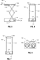
- FIG. 5 is a front elevation view of the adjustable elevation pet food feeder mechanism device 100 of FIG. 4 in an elevated position.
- FIG. 6 is a side elevation view of the adjustable elevation pet food feeder mechanism 100 of FIG. 5 in an elevated position.
- FIG. 7 is another side elevation view of the adjustable elevation pet food feeder mechanism device 100 of FIG. 2 in an elevated position on a side opposite to the side of FIG. 6 .
- FIG. 8 is a top plan view of the adjustable elevation pet food feeder mechanism device 100 of FIGS. 4-7 when in an elevated position.
- FIG. 9 is a perspective view in a lowered position of the adjustable elevation pet food feeder mechanism device 100 of FIG. 4 positioned within the actuating mechanism supporting tray 122.
- FIG. 10 is a front elevation view in a lowered position of the adjustable elevation pet food feeder mechanism device 100 of FIG. 9 positioned within the actuating mechanism supporting tray 122.
- FIG. 11 is a side elevation view in a lowered position of the adjustable elevation pet food feeder mechanism device 100 of FIG. 10 positioned within the actuating mechanism supporting tray 122.
- FIG. 12 is another side elevation view in a lowered position of the adjustable elevation pet food feeder mechanism device 100 of FIG. 10 positioned within the actuating mechanism supporting tray 122.
- FIG. 13 is a top plan view of the adjustable elevation pet food feeder mechanism device 100 of FIGS. 9-12 when in a lowered position positioned within the actuating mechanism supporting tray 122.
- FIG. 14 illustrates a pet food device 200 according to an aspect of the present disclosure wherein the actuating mechanism 14 includes a jack lift movable structure 210 of first lower legs 2102', 2104' and second lower legs 2112', 2114' and first upper legs 2102", 2104" and second upper legs 2112", 2114" that are in operable communication with the pet food bowl supporting tray 102 wherein a first cross-beam 2116a joins the first upper leg 2112' and second upper leg 2112" and a second cross-beam 2116b joins the first upper leg 2114' and second upper leg 2114" and both first cross-beam 2116a and second cross-beam 2116b support the pet food bowl supporting tray 102.
- a first cross-beam 2116a joins the first upper leg 2112' and second upper leg 2112"
- a second cross-beam 2116b joins the first upper leg 2114' and second upper leg 2114" and both first cross-beam 2116a and second cross-beam 2116
- first lower leg 2102' is joined to first upper leg 2102" and second lower leg 2112' is joined to second upper leg 2112" via a first cross-beam member 2106a at their intersection points 2106a' and 2106a", respectively.
- first lower leg 2104' is joined to first upper leg 2104" and second lower leg 2114' is joined to second upper leg 2114" via a second cross-beam member 2106b at their intersection points 2106b' and 2106b", respectively.
- First lower leg 2102' is rotatably coupled to a first brace member 232 while second lower leg 2104' is rotatably coupled to the pinion gear 2322 of a first rack and pinion set 232'.
- second lower leg 2112' is rotatably coupled to a second brace member 234 while second lower leg 2114' is rotatably coupled to the pinion gear 2342 of a second rack and pinion set 234'.
- Pinion gear 2322 of first rack and pinion set 232' is in operable communication with first rack 2321 while pinion gear 2342 of second rack and pinion set 234' is in operable communication with second rack 2341.
- First rack 2321 and second rack 2341 are interconnected by a common operating joining member 212 in the form, for example, of a cylindrical rod which in turn is operably coupled to actuating mechanism 14 in the form of linear actuator 214.
- Movement of the first rack 2321 and second rack 2341 by the common operating joining member 212 in the direction of dual headed arrow B causes rotation of the pinion gears 2322 and 2342 and thereby effecting elevating of or lowering of the pet food bowl supporting tray 102 by the jack lift movable structure 210.
- power cord 214' enables connection of the linear actuator 214 actuating mechanism to a standard 110 V or 220 V power source for actuation of the pet food device 200.
- a radio-frequency (RF) receiver 215 is in electrical communication with the linear actuator 214 to receive control signals CS as described above with respect to FIGS. 1-3 and further described below with respect to FIGS. 47-53 .
- FIG. 15 is a front elevation view of the adjustable elevation pet food feeder mechanism device 200 of FIG. 13 in an elevated position.
- FIG. 16 is a side elevation view of the adjustable elevation pet food feeder mechanism device 200 of FIG. 13 in an elevated position.
- FIG. 17 is a top plan view of the adjustable elevation pet food feeder mechanism device 200 of FIGS. 14-16 when in an elevated position.
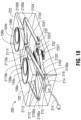
- FIG. 18 is a perspective view of the adjustable elevation pet food feeder mechanism device 200 of FIG. 14 in a lowered position positioned within the actuating mechanism supporting tray 222.
- FIG. 19 is a front elevation view of the adjustable elevation pet food feeder mechanism device 200 of FIG. 18 in a lowered position positioned within the actuating mechanism supporting tray 222.
- FIG. 20 is a side elevation view in a lowered position of the adjustable elevation pet food feeder mechanism device 200 of FIG. 19 .
- FIG. 21 is a top plan view of the adjustable elevation pet food feeder mechanism device 200 of FIGS. 18-20 when in a lowered position positioned within the actuating mechanism supporting tray 222.
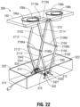
- FIG. 22 illustrates an adjustable elevation pet food feeder mechanism device 300 according to an aspect of the present disclosure.
- Pet food feeder mechanism device 300 is substantially identical to pet food feeder mechanism device 200 by including the pet food bowl supporting tray 102 wherein the actuating mechanism 14 of the pet food bowl supporting tray 102 includes the jack lift movable structure 210, as described above with respect to pet food feeder mechanism device 200 and FIGS.. 14-21 , but modified such that the actuating mechanism 14 includes motorized gears in operable communication with the jack lift movable structure 210 wherein the jack lift movable structure 210 and the motorized gears thereby effect the elevating of and lowering of the pet food bowl supporting tray 102.
- motorized gear set 330 which includes a motor 314 operably coupled to a dual rotatable operating shaft 312.
- First lower leg 2102' is rotatably coupled to first brace member 332 via a first gear 3321 while second lower leg 2104' is rotatably coupled to first brace member 332 via a second gear 3322.
- second lower leg 2112' is rotatably coupled to second brace member 334 via a first gear 3341 while second lower leg 2114' is rotatably coupled to second brace member 334 via a second gear 3342.
- the dual rotatable operating shaft 312 is now operably coupled either to first gear 3321 and first gear 3341 (not shown) or to second gear 3322 and second gear 3342 such that now rotation of the operating shaft 312 either clockwise or counterclockwise causes the jack lift movable structure 210 to thereby effect the elevating of and lowering of the pet food bowl supporting tray 102.
- a radio-frequency (RF) receiver 315 is in electrical communication with the motor 314 to receive control signals CS as described above with respect to FIGS. 1-3 and further described below with respect to FIGS. 47-53 .
- the motor 314, the RF receiver 315, the operating shaft 312, the gear set 330, the actuating mechanism 14 in the form of the jack lift movable structure 210 as described above and the pet food bowl supporting tray 102 at least partially or entirely reside in the actuating mechanism supporting tray 322 when the pet food device 300 is at least partially or entirely in the lowered position as illustrated in FIGS. 23-29 which follow.
- FIG. 23 is a front elevation view of the adjustable elevation pet food feeder mechanism device 300 of FIG. 22 in an elevated position.
- FIG. 24 is a side elevation view of the adjustable elevation pet food feeder mechanism device 300 of FIG. 23 in an elevated position.
- FIG. 25 is a top plan view of the adjustable elevation pet food feeder mechanism device 300 of FIGS. 22-24 when in an elevated position.
- FIG. 26 is a perspective view of the adjustable elevation pet food feeder mechanism device 300 of FIG. 22 in a lowered position positioned within the actuating mechanism supporting tray 322.
- FIG. 27 is a front elevation view of the adjustable elevation pet food feeder mechanism device 300 of FIG. 26 in a lowered position positioned within the actuating mechanism supporting tray 322.
- FIG. 28 is a side elevation view of the adjustable elevation pet food feeder mechanism device 300 of FIG. 27 in a lowered position positioned within the actuating mechanism supporting tray 322.
- FIG. 29 is a top plan view of the adjustable elevation pet food feeder mechanism device 300 of FIGS. 26-28 when in a lowered position positioned within the actuating mechanism supporting tray 322.
- FIG. 30 illustrates in an elevated position an adjustable elevation pet food feeder mechanism device 400 according to an aspect of the present disclosure.
- FIG. 31 is a perspective view in a lowered position of the adjustable elevation pet food feeder mechanism of FIG. 30 in a lowered position positioned within actuating mechanism supporting tray 422.
- pet food device 400 includes as pet food bowl supporting tray 12 pet food bowl supporting tray 1021 which is substantially identical to pet food bowl supporting tray 102 except for a rectangular space 1022 formed on one edge of the supporting tray 1021 that enables receiving of a riser panel 410 therein.
- Actuating mechanism 14 now includes riser panel 410 that is supported by actuating mechanism supporting tray 18 as represented by actuating mechanism supporting tray 422.
- a channel 412 is defined by a guide structure 416 mounted on or formed by vertical projecting edge 416 of the riser panel 410.
- a support connector member 414 is slidably disposed in the channel 412 and is operably coupled to the supporting tray 1021 within the rectangular space 1022.
- the support connector member 414 is also operably coupled to a chain link and gear set 436 that is configured to enable the support connector member 414 to slide in the channel 412 effecting thereby the elevating of and lowering of the pet food bowl supporting tray 1021.
- Actuating mechanism 14 also includes motor 434 on a mounting stand 432 that is fixedly positioned within actuating mechanism supporting tray 422.
- Motor 434 is operably coupled to a first gear 4361 at the lower end portion of the riser panel 410 that engages with a chain 438 that is mounted across the vertical flat surface 410' of the riser panel 410.
- Chain 438 also engages with a second gear 4362 at the upper end portion of the riser panel 410 thereby enabling the chain 438 and the support connector member 414 to move either vertically up or vertically down to enable the sliding in the channel 412 that effects the elevating of and lowering of the pet food bowl supporting tray 1021.
- the motor 434 is capable of either clockwise or counterclockwise rotation and, as before, is powered via power supplied by power cord 434' that enables connection of the motor 434 actuating mechanism to a standard 110 V or 220 V power source for actuation of the pet food device 400.
- a radio-frequency (RF) receiver 435 is in electrical communication with the motor 434 to receive control signals CS as described above with respect to FIGS. 1-3 and further described below with respect to FIGS. 47-53 .
- the motor 434, the RF receiver 435, the first gear 4361 and the lower end portion of the chain 438 and the pet food bowl supporting tray 1021 at least partially or entirely reside in the actuating mechanism supporting tray 422 when the pet food device 400 is at least partially or entirely in the lowered position as illustrated in FIG.31 .
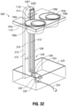
- FIG. 32 is a perspective view in an elevated position of an aspect of an adjustable elevation pet food feeder mechanism 500 according to the present disclosure.
- FIG. 33 is a perspective view of the adjustable elevation pet food feeder mechanism 500 of FIG. 32 in a lowered position positioned within actuating mechanism supporting tray 522.
- pet food device 500 includes as pet food bowl supporting tray 12 pet food bowl supporting tray 1121 which also is substantially identical to pet food bowl supporting tray 102 except for rectangular space 1122 formed on one edge of the supporting tray 1121 that enables receiving of riser panel 510 therein.
- Actuating mechanism 14 now includes riser panel 510 that is supported by actuating mechanism supporting tray 18 as represented by actuating mechanism supporting tray 522.
- a channel 512 is defined by vertical projection 516 that projects from front surface 510' of the riser panel 510.
- a support connector member 514 is slidably disposed in the channel 512 and is operably coupled to the supporting tray 1121 within the rectangular space 1122.
- the support connector member 514 is formed or connected at one end of a belt 538 included in a belt and pulley mechanism 540 wherein belt pulley wheel 536 is operably coupled to motor 534 such that the motor 534 and belt and pulley mechanism 540 are configured to enable the support connector member 514 to slide in the channel 512 effecting thereby the elevating of and lowering of the pet food bowl supporting tray 1021.
- Actuating mechanism 14 also includes motor 534 on a mounting stand 532 that is fixedly positioned within actuating mechanism supporting tray 522.
- Belt and pulley mechanism 540 also includes belt rotatable shafts 5401 and 5402 that are mounted at the upper end portion of the riser panel 510.
- First rotatable shaft 5401 is mounted in a position to enable the belt 538 to align with and pass through the open end of the channel 512 thereby enabling the support connector member 514 to be elevated or lowered within the channel 512 as a result of motion of the belt 538.
- a second rotatable shaft 5401 is mounted to enable the belt 538 to move and be positioned substantially parallel to the parallel walls of the vertical projection 516.that is mounted along the vertical flat surface 510' of the riser panel 510.
- motor 534 is capable of either clockwise or counterclockwise rotation and, as before, is powered via power supplied by power cord 534' that enables connection of the motor 534 actuating mechanism to a standard 110 V or 220 V power source for actuation of the pet food device 500.
- a radio-frequency (RF) receiver 535 is in electrical communication with the motor 534 to receive control signals CS as described above with respect to FIGS. 1-3 and further described below with respect to FIGS. 47-53 .
- the motor 534, the RF receiver 535, the lower end portion of the riser panel 510 and the belt pulley wheel 536 and the pet food bowl supporting tray 1121 at least partially or entirely reside in the actuating mechanism supporting tray 522 when the pet food device 500 is at least partially or entirely in the lowered position as illustrated in FIG.33 .
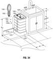
- FIG. 34 is a perspective view in an elevated position of another aspect of the adjustable elevation pet food feeder mechanism 100 of FIGS. 4-14 designated as pet food feeder mechanism device 1000 according to the present disclosure.
- pet food feeder mechanism device 1000 may be configured such that the pet food bowl supporting tray 1020 is within a comfortable position for a user to place bowls 106a and 106b in the sink 10 for washing, etc., such as height H D1 of the device 1000 in the elevated position as compared to height Hs of the sink 10.
- FIG. 35 is a plan view of the support tray 1220 containing the actuating components for the adjustable elevation pet food feeder mechanism 1000 of FIG. 34 ;
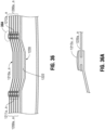
- FIG. 36 is a detailed plan view of telescoping shields 1200a... 1200n that may enclose the actuating components of the adjustable elevation pet food feeder mechanism 1000 of FIGS. 34-35 .
- FIG. 36A is a detailed view of a portion of the telescoping shields 1200a.. 1200n of FIG. 36 .
- actuating mechanism supporting tray 1220 defines an inner periphery 1221.
- a plurality of telescoping shields 1200a... 1200n configured as sequentially interlocking panels extend around the inner periphery 1221 of the actuating mechanism supporting tray 1220.
- the first of the plurality of telescoping shields 1200a is configured to interface with the inner periphery 1221 and defines an inner surface 1200a'.
- the second of the plurality of telescoping shields 1200b extends around the inner surface 1200a' of the first of the plurality of telescoping shields 1200a and each subsequent telescoping shield 1200c, 1200d, 1200e, wherein five shields are shown by way of example and not as a limitation, fewer or greater number of shields may be provided depending upon the particular design requirements or optional features, extends around the inner surface 1200b', 1200c', 1200d' of the prior telescoping shield 1200b, 1200c, 1200d.
- the final telescoping shield 1200e extends to contact the pet food bowl supporting tray 1020.
- the plurality of telescoping shields 1200a... 1200e each define a gap 1202a... 1202e in extending around the inner surface 1200a', 1200b', 1200c', 1200d' of the prior telescoping shield 1200a, 1200b, 1200c, 1200d.
- a plurality of connectors 1210a... 1210e, corresponding to the plurality of telescoping shields 1200a... 1200e are each configured to span the gap 1202a... 1202e in extending around the inner surface 1200a', 1200b', 1200c', 1200d' of the prior telescoping shield 1200a, 1200b, 1200c, 1200d.
- the connectors 1210a... 1210e are configured as linear guides that guide the telescoping shields 1200a, 1200b, 1200c, 1200d, 1200e to extend from a lowered position of the pet food device 1000 to an elevated position of the pet food device 1000.
- the connectors 1210a... 1210e have an arched configuration to enable flexing both of the connectors themselves and also of the telescoping shields 1200a, 1200b, 1200c, 1200d, 1200e so that the gaps 1202a... 102e can be adjusted to enable the connectors 1210a... 1210e to connect to the telescoping shields 1200a, 1200b, 1200c, 1200d, 1200e.
- An arched portion 1222 of the actuating mechanism supporting tray 1220 is configured to receive within and accommodate the arched configuration of the connectors 1210a... 1210e.
- the connectors 1210a... 1210e are best illustrated in FIGS. 36 and 36A in which side edges of the connectors 1210a... 1210e are integrally formed with as shown, or include separate, linear guides 1211a...1211e on a first end of the connectors 1210a... 1210e and linear guides 1212a...1212e.
- the linear guides 1211a...1211e and 1212a... 1212e are configured to receive and retain the open edges of telescoping shields 1200a, 1200b, 1200c, 1200d, 1200e so as to span the gaps formed between the open edges of the telescoping shields.
- FIG. 34 illustrates for comparison purposes of scale and size a wall-mounted telephone 1260 having a cord 1262 wherein the pet food device 1000 is positioned beneath the telephone 1260 and cord 1262 and adjacent to the sink 10.
- the linear guides 1211a...1211e and 1212a... 1212e enable the actuating mechanism 14 to telescope vertically upward or to collapse vertically downward the telescoping shields 1200a, 1200b, 1200c, 1200d, 1200e.
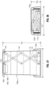
- FIG. 37 is a front elevation cross-sectional view in an elevated position of the adjustable elevation pet food feeder mechanism of FIGS. 34-36 illustrating the first scissor lift 1101 in an extended position to elevate the pet food bowl supporting tray 1020.
- FIG. 38 is a front elevation cross-sectional view in a lowered position of the adjustable elevation pet food feeder mechanism 1000 of FIGS. 34-37 illustrating the first scissor lift 1101 in a collapsed position to lower the pet food bowl supporting tray 1020.
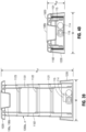
- FIG. 39 is a side elevation cross-sectional view in an elevated position of the adjustable elevation pet food feeder mechanism 1000 of FIGS. 34-38 illustrating both the first scissor lift 1101 and the second scissor lift 1102 in extended positions to elevate the pet food bowl supporting tray 1020.
- FIG. 40 is a side elevation cross-sectional view in a lowered position of the adjustable elevation pet food feeder mechanism 1000 of FIGS. 34-37 illustrating the first scissor lift 1101 and the second scissor lift 1102 in a collapsed position to lower the pet food bowl supporting tray 1020.
- FIG. 41 is a perspective view in an elevated position of a portion of the telescoping shields 1200a, 1200b, 1200c, 1200d, 1200e of the adjustable elevation pet food feeder mechanism 1000 of FIGS. 34-40 wherein the linear guides or connectors 1210a... 1210e enable the telescoping shields 1200a, 1200b, 1200c, 1200d, 1200e to properly extend and to maintain the pet food bowl supporting tray 1020 in the elevated position.
- FIG. 42 is a cross-sectional view of the telescoping shields 1200a-1200d wherein a portion of the telescoping shields, i. e., 1200a-1 are in a lowered position in the support tray and a portion in an elevated position
- the first of the plurality of telescoping shields 1200a is configured to interface with the inner periphery 1221 and defines inner surface 1200a'.
- the second of the plurality of telescoping shields 1200b extends around the inner surface 1200a' of the first of the plurality of telescoping shields 1200a and each subsequent telescoping shield 1200c, 1200d as shown for illustration, wherein fifth shield 1200e is not shown, extends around the inner surface 1200b', 1200c', 1200d' of the prior telescoping shield 1200b, 1200c, 1200d.
- the final telescoping shield 1200e not shown, extends to contact the pet food bowl supporting tray 1020.
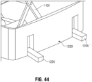
- FIG. 43 is a perspective view of the support tray 1220 for the adjustable elevation pet food feeder mechanisms having stabilization legs 1225' and 1225" in an elevated position in the support tray 1220.
- Stabilization legs 1225' and 1225" may be included on an optional basis since the weight of the actuating mechanisms represented by actuating mechanism 14 in FIG. 1 may preclude the need for the stabilization legs 1225' and 1225".
- FIG. 44 is a perspective view of the support tray 1220 of FIG. 43 wherein the stabilization legs 1225' and 1225" are in a lowered position with respect to the support tray 1220 to enable stabilization of the adjustable elevation pet food feeder mechanisms 10 of FIG. 1 .
- FIG. 45 is an exploded perspective view of the adjustable elevation pet food feeder mechanism 1000 of FIGS. 4-13 and FIGS. 34-44 . As further explained below, a radio-frequency transmitter 1230 is also shown; this is part of the actuating mechanism control 16 of FIG. 1 .
- FIG. 46 is a perspective view of the adjustable elevation pet food feeder mechanism 1000 of FIGS. 34-45 .
- telescoping shields 1200a... 1200n and the associated components such as the connectors 1210a... 1210e, the linear guides 1211a...1211e and linear guides 1212a... 1212e may be applied to the other aspects of the present disclosure of pet food devices such as shown and described above with respect to FIGS. 14-33 .
- the actuating mechanism effects the elevating of and lowering of the pet food bowl supporting tray in a height dimension H D1 -H D2 over a period of time ⁇ T in a time dimension of at least 3 centimeters/second (cm/sec) to define a minimum velocity V of elevating and lowering the pet food bowl supporting tray.
- the pet food device 100 transfers between an elevated position and a lowered position to define an average minimum velocity of the height differential of 60 centimeters over a period of 20 seconds or at least 3 cm/sec.
- the actuating mechanism supporting tray may be configured with an average area A' of length L multiplied by width W wherein A' may be not greater than 2700 sq. centimeters.
- A' divided by the minimum velocity V of elevating and lowering the pet food bowl supporting tray of 3 cm/sec may be not greater than 900 centimeter-seconds.
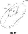
- FIG. 47 is a perspective view of actuating mechanism control 16 of FIG. 1 in the form of remote controller 1230 for the adjustable elevation pet food feeder devices 10 of FIGS. 1-46 .
- a power supply such as power cord 114' in FIG. 35
- power is supplied to the actuating mechanism 14 in FIG. 1 , e. g, linear actuator 114 in FIG. 35 via a power control switch (not shown) that is included with the linear actuator 114, and radio-frequency receiver 115 that is in communication with the power control switch to enable control of the actuating mechanism 114 via radio-frequency transmitter 1230 communicating a signal to the power control switch via the radio-frequency receiver 115 to at least partially elevate or at least partially lower the pet food bowl supporting tray 1020.
- FIG. 48 illustrates wherein the actuating mechanism control 16 of FIG. 1 is in the form of a mobile device 1240 having a software application which enables raising and lowering the adjustable elevation pet food feeder devices 10 of FIGS. 1-46 .
- a power supply such as power cord 114' in FIG. 35
- power is supplied to the actuating mechanism 14 in FIG. 1 , e. g, linear actuator 114 in FIG.
- a power control switch (not shown) that is included with the linear actuator 114, and radio-frequency receiver 115 that is in communication with the power control switch to enable control of the actuating mechanism 114 to the actuating mechanism including a power control switch; and a computing device 20 in FIG. 2 including a processor 24 and a memory 21 storing instructions which, when executed by at least one processor 24, causes the computing device 20, e.g., mobile device 1240 in FIG. 48 , to communicate instructions to radio-frequency receiver 115 that is in communication with the power control switch (not shown) in the linear actuator 114 to enable control of the actuating mechanism 14, e.
- linear actuator 114 by communicating a signal to the power control switch via the radio-frequency receiver 115 to at least partially elevate or at least partially lower the pet food bowl supporting tray 1020 in FIGS. 34-42 .
- a control signal is transmitted to the radio-frequency receiver 115 to elevate the pet food feeder device 10.
- LOWER button 1234'
- a control signal is transmitted to the radio-frequency receiver 115 to lower the pet food feeder device 10.
- user device 10 and computing device 20 may each be a distinct device, or may be a single device performing the functions of both devices.
- the examples described herein refer to user device 10 and computing device 20 as distinct devices. However, these examples are not intended to be limiting, and those skilled in the art will recognize that the same or similar functions described below may be performed by a single, unified device.
- FIG. 49 is a view of the mobile device 1240 of FIG. 48 illustrating specific actuation features 1236 enabled by the software application.
- the actuation features 1236 may include: “Manual Mode” for raising and lowering the pet food bowl supporting tray 1020 in FIG. 34-42 , a "Time Presets” feature, a “Feed Time Reminders” feature, a “Height Presets” feature, and a “Settings” feature.
- FIG. 50 is a view of the mobile device 1240 of FIG. 49 wherein the user has selected to adjust the specific actuation features enabled by the software application of "Time Preset" 1242 that is included in the actuation features 1236.
- FIG. 51 is view of time settings 1244 for the software application to lower and raise the adjustable elevation pet food feeders of FIGS. 1-46 .
- Time settings 1244 include "Lower Bowl - 8:15 AM”, “Raise Bowl - 9:00 AM”, “Lower Bowl - 6:00 PM” and “Raise Bowl - 6:45 AM”.
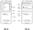
- FIG. 52 is a view of additional settings for the software application wherein setting 1248 includes "Feed Dog-Everyday @5:45 pm" to feed a pet or setting 1250 "Give Dog Heartworm Meds.” to give medications.
- FIG. 53 is a view of additional settings enabled by the software application wherein setting 1248 "Feed Dog-- Everyday @8:00 am” includes setting 1252 “Buy Dog Feed” to purchase pet food and setting 1254 "Redeem 10% Off-Coupon”.
- FIGS. 1-46 While the pet food feeders of FIGS. 1-46 have been shown to be controlled wirelessly remotely via a radio-frequency transceiver system or an application via Wi-Fi, those skilled in the art will recognize and understand that other control means may be employed including hard-wired systems or optical systems or the like. The aspects are not limited in this context.
Landscapes
- Life Sciences & Earth Sciences (AREA)
- Environmental Sciences (AREA)
- Birds (AREA)
- Animal Husbandry (AREA)
- Biodiversity & Conservation Biology (AREA)
- Feeding And Watering For Cattle Raising And Animal Husbandry (AREA)
Claims (13)
- Haustierfuttervorrichtung, umfassend:ein Haustierfutterschalen-Tragetablett, das mit mindestens einer ersten und zweiten Aufnahmestruktur ausgelegt ist, wobei die erste und zweite Aufnahmestruktur eine Öffnung oder eine Hohlraumvertiefung oder Kombinationen davon umfassen, wobei jede der ersten und zweiten Aufnahmestruktur dazu ausgelegt ist, mindestens eine Haustierfutterschale aufzunehmen;ein Betätigungsmechanismus-Tragetablett; undeinen Betätigungsmechanismus, der innerhalb des Betätigungsmechanismus-Tragetabletts in funktionsfähiger Verbindung mit dem Haustierfutterschalen-Tragetablett angeordnet ist,wobei der Betätigungsmechanismus das gleichzeitige Heben des Haustierfutterschalen-Tragetabletts über das Betätigungsmechanismus-Tragetablett und mindestens einer aus einer Vielzahl von teleskopischen Abschirmungen ermöglicht, die dazu ausgelegt und angeordnet sind, das Betätigungsmechanismus-Tragetablett von der Umgebung abzuschirmen, und das gleichzeitige Absenken des Haustierfutterschüssel-Tragetabletts und der mindestens einen der Vielzahl von teleskopischen Abschirmungen ermöglicht, um mit dem Betätigungsmechanismus-Tragetablett zusammenzukommen, wobei der Betätigungsmechanismus eine bewegbare Scherenhubstruktur in funktionsfähiger Verbindung mit dem Haustierfutterschüssel-Tragetablett und mit dem Betätigungsmechanismus umfasst,wobei die bewegbare Scherenhubstruktur und der Betätigungsmechanismus dadurch das Heben und Senken des Haustierfutterschalen-Tragetabletts bewirken,wobei die bewegbare Scherenhubstruktur betriebsfähig mit dem Haustierfutterschalen-Tragetablett so gekoppelt ist, dass die erste Aufnahmestruktur mindestens teilweise von der bewegbaren Scherenhubstruktur absteht und mindestens teilweise das Betätigungsmechanismus-Tragetablett überragt, wenn sich das Haustierschalen-Tragetablett in einer angehobenen Position befindet;wobei das Betätigungsmechanismus-Tragetablett einen Innenumfang definiert, wobei die Haustierfuttervorrichtung die Vielzahl von teleskopischen Abschirmungen umfasst, die als aufeinanderfolgend ineinandergreifende Platten ausgelegt sind, die sich um den Innenumfang des Betätigungsmechanismus-Tragetabletts erstrecken.
- Haustierfuttervorrichtung gemäß Anspruch 1, wobei der Betätigungsmechanismus einen Linearaktuator in funktionsfähiger Verbindung mit einem Verbindungsstangenelement umfasst, wobei das Verbindungsstangenelement in funktionsfähiger Verbindung mit der bewegbaren Scherenhubstruktur steht, wobei die Bewegung des Verbindungsstangenelements durch den Linearaktuator das Heben und Senken des Haustierfutterschalen-Tragetabletts bewirkt.
- Haustierfuttervorrichtung gemäß Anspruch 1, wobei der Betätigungsmechanismus das Heben und Senken des Haustierfutterschalen-Tragetabletts in einer Höhendimension über eine Zeitspanne in einer Zeitdimension bewirkt, um eine Mindestgeschwindigkeit des Hebens und Senkens des Haustierfutterschalen-Tragetabletts von mindestens 3 Zentimeter/Sekunde (cm/s) zu definieren.
- Haustierfuttervorrichtung gemäß Anspruch 3, wobei das Betätigungsmechanismus-Tragetablett mit einer durchschnittlichen Fläche aus Länge mal Breite ausgelegt ist, und wobei die durchschnittliche Fläche dividiert durch die Mindestgeschwindigkeit des Hebens und Senkens des Haustierfutterschalen-Tragetabletts nicht größer als 900 Zentimeter-Sekunden ist.
- Haustierfuttervorrichtung gemäß Anspruch 1,
wobei die erste der Vielzahl von teleskopischen Abschirmungen so ausgelegt ist, sie mit dem Innenumfang des Betätigungsmechanismus-Tragetabletts in Berührung kommt, die erste der Vielzahl von teleskopischen Abschirmungen eine Innenfläche definiert, die zweite der Vielzahl von teleskopischen Abschirmungen sich um die Innenfläche der ersten der Vielzahl von teleskopischen Abschirmungen herum erstreckt und jede nachfolgende teleskopische Abschirmung sich um die Innenfläche der vorherigen teleskopische Abschirmung herum erstreckt, wobei die letzte teleskopische Abschirmung sich so erstreckt, dass sie das Haustierfutterschalen-Tragetablett berührt. - Haustierfuttervorrichtung gemäß Anspruch 5,wobei die Vielzahl von teleskopischen Abschirmungen jeweils einen Spalt definieren, der sich um die Innenfläche der vorherigen teleskopischen Abschirmung erstreckt,wobei die Haustierfuttervorrichtung eine Vielzahl von Verbindern umfasst, die der Vielzahl von teleskopischen Abschirmungen entsprechen, wobei die Vielzahl von Verbindern jeweils so ausgelegt ist, dass sie den Spalt überspannen, der sich um die Innenfläche der vorherigen teleskopischen Abschirmung erstreckt,wobei die Verbinder als lineare Führungen ausgelegt sind, die die teleskopischen Abschirmungen so führen, dass sie sich von einer abgesenkten Position der Haustierfuttervorrichtung in eine angehobene Position der Haustierfuttervorrichtung erstrecken.
- Haustierfuttervorrichtung gemäß Anspruch 1, wobei das Betätigungsmechanismus-Tragetablett mindestens eine Kippschutzstruktur enthält, die dazu ausgelegt ist, einen Widerstand gegen das Umkippen der Haustierfuttervorrichtung zu bieten.
- Haustierfuttervorrichtung gemäß Anspruch 7, wobei die mindestens eine Kippschutzstruktur als mindestens ein drehbares Stabilisierungsbein ausgelegt ist, das dazu ausgelegt und angeordnet ist, sich aus einer Nichtgebrauchsposition in eine Gebrauchsposition zu drehen, wobei das mindestens eine Stabilisierungsbein in der Gebrauchsposition von einer Seitenwand des Betätigungsmechanismus-Tragetabletts vorsteht.
- Haustierfuttervorrichtung gemäß Anspruch 1, umfassend:eine Stromversorgung für den Betätigungsmechanismus mit einem Leistungssteuerungsschalter; und einenFunkempfänger, der mit dem Leistungssteuerungsschalter in Verbindung steht, um die Steuerung des Betätigungsmechanismus über einen Funksender zu ermöglichen, der über den Funkempfänger ein Signal an den Leistungssteuerungsschalter übermittelt, um die Haustierfutterschale mindestens teilweise zu heben oder mindestens teilweise zu senken.
- Haustierfuttervorrichtung gemäß Anspruch 1, umfassend:eine Stromversorgung für den Betätigungsmechanismus mit einem Leistungssteuerungsschalter; und einenRecheneinrichtung mit einem Prozessor und einem Speicher, der Anweisungen speichert, die beim Ausführen durch mindestens einen Prozessor die Recheneinrichtung veranlassen, Anweisungen an einen Funkempfänger zu übermitteln, der mit dem Leistungssteuerungsschalter in Verbindung steht, um die Steuerung des Betätigungsmechanismus durch Übermitteln eines Signals an den Leistungssteuerungsschalter über den Funkempfänger zu ermöglichen, um die Haustierfutterschale mindestens teilweise zu heben oder mindestens teilweise zu senken.
- Haustierfuttervorrichtung gemäß Anspruch 10, wobei die Recheneinrichtung mit dem Prozessor und dem Speicher Anweisungen speichert, die beim Ausführen durch mindestens einen Prozessor die Recheneinrichtung veranlassen, eines aus Zeitvorgaben oder Fütterungszeitvorgaben oder Höhenvorgaben oder Einstellungen oder Kombinationen davon einzurichten.
- Haustierfuttervorrichtung gemäß Anspruch 11, wobei die Zeitvorgaben einen aus mindestens einem Zeitpunkt zum Heben des Haustierfutterschalen-Tragetabletts oder zum Senken des Haustierfutterschalen-Tragetabletts oder Kombinationen davon enthalten.
- Haustierfuttervorrichtung gemäß Anspruch 11, wobei die Fütterungszeiterinnerungen mindestens einen Zeitpunkt für die Fütterung eines Haustiers oder mindestens einen Zeitpunkt für die Verabreichung von Medikamenten an ein Haustier oder mindestens einen Zeitpunkt für die Beschaffung von Haustierfutter oder Kombinationen davon umfassen.
Applications Claiming Priority (2)
| Application Number | Priority Date | Filing Date | Title |
|---|---|---|---|
| US16/179,172 US10524451B1 (en) | 2018-11-02 | 2018-11-02 | Adjustable elevation pet food feeder mechanism device and control system |
| PCT/US2019/059324 WO2020092867A1 (en) | 2018-11-02 | 2019-11-01 | Adjustable elevation pet food feeder mechanism device and control system |
Publications (3)
| Publication Number | Publication Date |
|---|---|
| EP3873202A1 EP3873202A1 (de) | 2021-09-08 |
| EP3873202A4 EP3873202A4 (de) | 2021-12-15 |
| EP3873202B1 true EP3873202B1 (de) | 2023-07-05 |
Family
ID=69058443
Family Applications (1)
| Application Number | Title | Priority Date | Filing Date |
|---|---|---|---|
| EP19880306.6A Active EP3873202B1 (de) | 2018-11-02 | 2019-11-01 | Vorrichtung mit anpassbarem mechanismus für erhöhten haustierfütterer |
Country Status (7)
| Country | Link |
|---|---|
| US (1) | US10524451B1 (de) |
| EP (1) | EP3873202B1 (de) |
| KR (1) | KR102313522B1 (de) |
| CN (1) | CN113194714B (de) |
| AU (1) | AU2019371390B2 (de) |
| CA (1) | CA3118437C (de) |
| WO (1) | WO2020092867A1 (de) |
Families Citing this family (14)
| Publication number | Priority date | Publication date | Assignee | Title |
|---|---|---|---|---|
| US11109567B2 (en) * | 2018-04-06 | 2021-09-07 | Sherry Lynn Matheson | Splash-guard system and method |
| US11013213B1 (en) * | 2018-07-15 | 2021-05-25 | Lori Gelinas | Pet food dispenser |
| US11044890B2 (en) * | 2018-08-16 | 2021-06-29 | Jared Marker | Adjustable animal feeder |
| US20220210999A1 (en) * | 2021-01-05 | 2022-07-07 | Richard Ross | Feeding system for an animal |
| CA3112174C (en) * | 2021-03-17 | 2023-05-23 | Xanantec Technologies Inc. | Improved system for feeding animals |
| DE102021001707B4 (de) | 2021-04-01 | 2023-01-12 | Marcel Oberstadt | Höhenverstellbare Aufnahmevorrichtungen für Tiernahrung |
| DE102021126790B3 (de) * | 2021-10-15 | 2023-01-26 | Vogel und Weber UG (haftungsbeschränkt) | Futterlift |
| KR102708226B1 (ko) * | 2021-10-25 | 2024-09-20 | 엘지전자 주식회사 | 반려동물용 음식물 공급장치 및 그의 제어방법 |
| KR102698967B1 (ko) * | 2021-10-25 | 2024-08-23 | 엘지전자 주식회사 | 반려동물용 음식물 공급장치 |
| KR102708224B1 (ko) * | 2021-10-25 | 2024-09-20 | 엘지전자 주식회사 | 반려동물용 음식물 공급장치 |
| CN114600783B (zh) * | 2022-03-29 | 2023-06-02 | 滕州市畜牧渔业事业发展中心 | 一种畜牧养殖用喂食系统 |
| USD1048583S1 (en) * | 2022-09-28 | 2024-10-22 | Jindong Xia | Adjustable pet feeder |
| CN219660640U (zh) * | 2023-02-01 | 2023-09-12 | 中山市凯恩德宠物用品有限公司 | 一种户外折叠宠物用餐桌 |
| KR102732283B1 (ko) * | 2023-05-02 | 2024-11-20 | (주)펫츠아일랜드 | 휴대용 반려동물 사료통 |
Family Cites Families (44)
| Publication number | Priority date | Publication date | Assignee | Title |
|---|---|---|---|---|
| US4232901A (en) * | 1979-10-12 | 1980-11-11 | Harrington Elaine M | Adjustable ottoman |
| DE3208400C2 (de) * | 1982-03-09 | 1985-08-22 | Expert Maschinenbau Gmbh, 6143 Lorsch | Scheren-Hubtisch mit Schrittantrieb |
| US4658759A (en) * | 1985-07-11 | 1987-04-21 | Brown Elizabeth A | Adjustable dog feeding tray means |
| US4976223A (en) * | 1988-09-09 | 1990-12-11 | Wesley L. Pierce | Adjustable animal feeding apparatus |
| US4976233A (en) * | 1989-05-11 | 1990-12-11 | K.J. Manufacturing | Quick connect coupling adapters for facilitating simple and high speed oil change in an internal combustion engine |
| US5054431A (en) * | 1989-12-04 | 1991-10-08 | Coviello Andrew G | Adjustable animal feeder |
| US5285992A (en) * | 1992-07-14 | 1994-02-15 | Brown Ronald G | Adjustable step stool |
| US5501176A (en) * | 1994-09-16 | 1996-03-26 | Tully; Tara S. | Pet feeding apparatus |
| US5584263A (en) * | 1995-09-21 | 1996-12-17 | Sexton; James E. | Pet food dish elevating assembly |
| US20030106498A1 (en) * | 2001-12-07 | 2003-06-12 | Thomas Mersits | Pet food serving apparatus and methods |
| ITBO20040589A1 (it) * | 2004-09-22 | 2004-12-22 | Gd Spa | Metodo e unita' per applicare un'etichetta ad un articolo |
| US20060075974A1 (en) * | 2004-10-07 | 2006-04-13 | Patrick Kennedy | Insect proof food and/or water dish |
| US20060096545A1 (en) * | 2004-11-05 | 2006-05-11 | Cone Danny J | Pet feeder apparatus |
| US20060272893A1 (en) * | 2005-05-26 | 2006-12-07 | Joe Foggio | Therapeutic foot/leg/knee elevation |
| US7318391B2 (en) | 2005-06-23 | 2008-01-15 | Daniel Brillon | Food lifter |
| US20070089678A1 (en) * | 2005-10-21 | 2007-04-26 | Petstages, Inc. | Pet feeding apparatus having adjustable elevation |
| US20080023479A1 (en) * | 2006-07-25 | 2008-01-31 | Abbas Sadriwalla | Adjustable animal feeder |
| US20080035066A1 (en) * | 2006-08-12 | 2008-02-14 | Enriquez Ross J | All in one pet caddy |
| CA2646215C (en) * | 2008-12-11 | 2015-04-07 | George Aletti | Pet food elevating device |
| CN201444806U (zh) * | 2009-06-15 | 2010-05-05 | 无锡职业技术学院 | 可调节碗盆高度的宠物碗架 |
| CN201571392U (zh) * | 2009-12-14 | 2010-09-08 | 杨卫平 | 喂食架 |
| US8479686B2 (en) | 2011-11-03 | 2013-07-09 | Matthew T. Johnson | Pet feeder system for a handicapped pet owner |
| CN202588042U (zh) * | 2012-04-16 | 2012-12-12 | 江苏中恒宠物用品股份有限公司 | 伸缩型喂食器 |
| US8776725B1 (en) * | 2012-05-21 | 2014-07-15 | Enedina Grijalva | Pet waiter systems |
| EP2676918B1 (de) * | 2012-06-20 | 2015-05-27 | Develtex ApS | Scherenhebebühne und Verwendung dieser Scherenhebebühne |
| CN202652970U (zh) * | 2012-07-03 | 2013-01-09 | 江苏中恒宠物用品股份有限公司 | 可升降狗碗支架 |
| CN203261965U (zh) * | 2013-02-22 | 2013-11-06 | 杨天乐 | 一种组合式折叠宠物桌子 |
| CN203194275U (zh) * | 2013-03-14 | 2013-09-18 | 黄耀勋 | 宠物食器之支架座 |
| US9288967B1 (en) * | 2014-03-06 | 2016-03-22 | Sheril A. Wampler | Pet care systems |
| US20150308615A1 (en) * | 2014-04-29 | 2015-10-29 | Evan R Neaves | Bed-Mounted Pet Feeder with Adjustable Stand |
| US20150313176A1 (en) * | 2014-04-30 | 2015-11-05 | Lori Gelinas | Pet Feeding System |
| US9144225B1 (en) * | 2014-11-18 | 2015-09-29 | Barbara Gaccione | Elevationally-adjustable pet feeding and water bowl holders |
| EP3226681B1 (de) * | 2014-12-02 | 2022-01-05 | Vet Innovations, Llc | System für den selektiven zugang von bestimmten haustieren zu einem bestimmten ort oder objekt |
| US20160242385A1 (en) * | 2015-02-20 | 2016-08-25 | Michael Parness | Telescopic adjustable portion control pet feeder |
| US10149456B2 (en) * | 2015-04-28 | 2018-12-11 | Nextek Corporation | Vertically moving pet bowl apparatus |
| KR200484820Y1 (ko) * | 2015-06-09 | 2017-10-30 | 김민정 | 애완동물용 사료공급기구 |
| TW201700006A (zh) * | 2015-06-26 | 2017-01-01 | Sdy International Co Ltd | 寵物餵食器結構 |
| US10098321B2 (en) * | 2016-02-03 | 2018-10-16 | Shannon McKay | Cold water dispensing device |
| US10052764B2 (en) * | 2016-06-16 | 2018-08-21 | Toyota Motor Engineering & Manufacutring North America, Inc. | Automated and adjustable platform surface |
| CN106165653A (zh) * | 2016-08-22 | 2016-11-30 | 无锡东晟生物科技有限公司 | 一种方便使用的壁挂式宠物喂食装置 |
| CN106135033A (zh) * | 2016-08-22 | 2016-11-23 | 无锡东晟生物科技有限公司 | 一种可调节高度的宠物喂食装置 |
| CN206005491U (zh) * | 2016-08-22 | 2017-03-15 | 无锡东晟生物科技有限公司 | 一种方便使用的壁挂式宠物喂食装置 |
| CN206005484U (zh) * | 2016-08-22 | 2017-03-15 | 无锡东晟生物科技有限公司 | 一种可调节高度的宠物喂食装置 |
| CN206851692U (zh) * | 2017-05-15 | 2018-01-09 | 珠海横琴休普科技有限公司 | 一种具有存储功能的组合式升降碗 |
-
2018
- 2018-11-02 US US16/179,172 patent/US10524451B1/en active Active
-
2019
- 2019-11-01 AU AU2019371390A patent/AU2019371390B2/en active Active
- 2019-11-01 KR KR1020217015212A patent/KR102313522B1/ko active Active
- 2019-11-01 EP EP19880306.6A patent/EP3873202B1/de active Active
- 2019-11-01 WO PCT/US2019/059324 patent/WO2020092867A1/en not_active Ceased
- 2019-11-01 CA CA3118437A patent/CA3118437C/en active Active
- 2019-11-01 CN CN201980083966.7A patent/CN113194714B/zh active Active
Also Published As
| Publication number | Publication date |
|---|---|
| CN113194714A (zh) | 2021-07-30 |
| US10524451B1 (en) | 2020-01-07 |
| KR20210066931A (ko) | 2021-06-07 |
| EP3873202A1 (de) | 2021-09-08 |
| CA3118437C (en) | 2021-11-23 |
| WO2020092867A1 (en) | 2020-05-07 |
| AU2019371390B2 (en) | 2021-07-01 |
| EP3873202A4 (de) | 2021-12-15 |
| CN113194714B (zh) | 2022-11-11 |
| KR102313522B1 (ko) | 2021-10-14 |
| CA3118437A1 (en) | 2020-05-07 |
| AU2019371390A1 (en) | 2021-05-27 |
Similar Documents
| Publication | Publication Date | Title |
|---|---|---|
| CA3118437C (en) | Adjustable elevation pet food feeder mechanism device and control system | |
| US11983986B2 (en) | Method and system for a gaming system user interface | |
| EP3960142B1 (de) | Modulares chirurgisches system | |
| US10178868B2 (en) | 3D-print system with integrated CNC robot and automatic self-cleaning mechanism | |
| KR102124694B1 (ko) | 높이 조절 및 이동이 용이한 키오스크 | |
| US20140360411A1 (en) | Desk stand | |
| US8526178B2 (en) | All-in-one computing device with an adjustable screen height | |
| CN209373956U (zh) | 一种基于物联网电子信息显示牌 | |
| JP2019069081A (ja) | ゲームプログラム、ゲーム処理方法、および情報端末装置 | |
| CN103381299A (zh) | 一种多功能无线游戏手柄 | |
| CN104887164B (zh) | 洗碗机的刀叉架上下调节机构 | |
| CN102541185A (zh) | 一种用于平板电脑的辅助装置及其对应的调整设备 | |
| CN103625523B (zh) | 一种机房移动运维装置 | |
| CN106128179A (zh) | 一种用于助教机器人的感应自平衡置物台 | |
| CN205750647U (zh) | 一种可自动升降隐蔽的一体机台式电脑 | |
| CN203748899U (zh) | 多媒体茶几 | |
| CN219863923U (zh) | 一种施工平台 | |
| KR20170057845A (ko) | 3차원 프린터 | |
| CN203485963U (zh) | 一种机房移动运维装置 | |
| CN219660186U (zh) | 一种通讯用模拟器 | |
| CN110486599B (zh) | 一种具有升降功能的显示器固定装置 | |
| CN207519946U (zh) | 一种可远程遥控的床垫智能展示系统 | |
| CN107307600A (zh) | 一种具有自动移动块的智能茶几 | |
| KR101546964B1 (ko) | 게임테이블 장치 및 이를 이용한 게임방법 | |
| WO2020170086A1 (en) | Apparatus for accommodating a computer |
Legal Events
| Date | Code | Title | Description |
|---|---|---|---|
| STAA | Information on the status of an ep patent application or granted ep patent |
Free format text: STATUS: THE INTERNATIONAL PUBLICATION HAS BEEN MADE |
|
| PUAI | Public reference made under article 153(3) epc to a published international application that has entered the european phase |
Free format text: ORIGINAL CODE: 0009012 |
|
| STAA | Information on the status of an ep patent application or granted ep patent |
Free format text: STATUS: REQUEST FOR EXAMINATION WAS MADE |
|
| 17P | Request for examination filed |
Effective date: 20210526 |
|
| AK | Designated contracting states |
Kind code of ref document: A1 Designated state(s): AL AT BE BG CH CY CZ DE DK EE ES FI FR GB GR HR HU IE IS IT LI LT LU LV MC MK MT NL NO PL PT RO RS SE SI SK SM TR |
|
| A4 | Supplementary search report drawn up and despatched |
Effective date: 20211116 |
|
| RIC1 | Information provided on ipc code assigned before grant |
Ipc: A01K 5/01 20060101AFI20211110BHEP |
|
| DAV | Request for validation of the european patent (deleted) | ||
| DAX | Request for extension of the european patent (deleted) | ||
| GRAP | Despatch of communication of intention to grant a patent |
Free format text: ORIGINAL CODE: EPIDOSNIGR1 |
|
| STAA | Information on the status of an ep patent application or granted ep patent |
Free format text: STATUS: GRANT OF PATENT IS INTENDED |
|
| INTG | Intention to grant announced |
Effective date: 20220812 |
|
| GRAJ | Information related to disapproval of communication of intention to grant by the applicant or resumption of examination proceedings by the epo deleted |
Free format text: ORIGINAL CODE: EPIDOSDIGR1 |
|
| STAA | Information on the status of an ep patent application or granted ep patent |
Free format text: STATUS: REQUEST FOR EXAMINATION WAS MADE |
|
| INTC | Intention to grant announced (deleted) | ||
| GRAP | Despatch of communication of intention to grant a patent |
Free format text: ORIGINAL CODE: EPIDOSNIGR1 |
|
| STAA | Information on the status of an ep patent application or granted ep patent |
Free format text: STATUS: GRANT OF PATENT IS INTENDED |
|
| INTG | Intention to grant announced |
Effective date: 20230119 |
|
| GRAS | Grant fee paid |
Free format text: ORIGINAL CODE: EPIDOSNIGR3 |
|
| GRAA | (expected) grant |
Free format text: ORIGINAL CODE: 0009210 |
|
| STAA | Information on the status of an ep patent application or granted ep patent |
Free format text: STATUS: THE PATENT HAS BEEN GRANTED |
|
| AK | Designated contracting states |
Kind code of ref document: B1 Designated state(s): AL AT BE BG CH CY CZ DE DK EE ES FI FR GB GR HR HU IE IS IT LI LT LU LV MC MK MT NL NO PL PT RO RS SE SI SK SM TR |
|
| REG | Reference to a national code |
Ref country code: CH Ref legal event code: EP |
|
| REG | Reference to a national code |
Ref country code: AT Ref legal event code: REF Ref document number: 1583923 Country of ref document: AT Kind code of ref document: T Effective date: 20230715 |
|
| REG | Reference to a national code |
Ref country code: DE Ref legal event code: R096 Ref document number: 602019032348 Country of ref document: DE |
|
| REG | Reference to a national code |
Ref country code: IE Ref legal event code: FG4D |
|
| REG | Reference to a national code |
Ref country code: LT Ref legal event code: MG9D |
|
| REG | Reference to a national code |
Ref country code: NL Ref legal event code: MP Effective date: 20230705 |
|
| REG | Reference to a national code |
Ref country code: AT Ref legal event code: MK05 Ref document number: 1583923 Country of ref document: AT Kind code of ref document: T Effective date: 20230705 |
|
| PG25 | Lapsed in a contracting state [announced via postgrant information from national office to epo] |
Ref country code: NL Free format text: LAPSE BECAUSE OF FAILURE TO SUBMIT A TRANSLATION OF THE DESCRIPTION OR TO PAY THE FEE WITHIN THE PRESCRIBED TIME-LIMIT Effective date: 20230705 |
|
| PG25 | Lapsed in a contracting state [announced via postgrant information from national office to epo] |
Ref country code: GR Free format text: LAPSE BECAUSE OF FAILURE TO SUBMIT A TRANSLATION OF THE DESCRIPTION OR TO PAY THE FEE WITHIN THE PRESCRIBED TIME-LIMIT Effective date: 20231006 |
|
| PG25 | Lapsed in a contracting state [announced via postgrant information from national office to epo] |
Ref country code: ES Free format text: LAPSE BECAUSE OF FAILURE TO SUBMIT A TRANSLATION OF THE DESCRIPTION OR TO PAY THE FEE WITHIN THE PRESCRIBED TIME-LIMIT Effective date: 20230705 |
|
| PG25 | Lapsed in a contracting state [announced via postgrant information from national office to epo] |
Ref country code: IS Free format text: LAPSE BECAUSE OF FAILURE TO SUBMIT A TRANSLATION OF THE DESCRIPTION OR TO PAY THE FEE WITHIN THE PRESCRIBED TIME-LIMIT Effective date: 20231105 |
|
| PG25 | Lapsed in a contracting state [announced via postgrant information from national office to epo] |
Ref country code: SE Free format text: LAPSE BECAUSE OF FAILURE TO SUBMIT A TRANSLATION OF THE DESCRIPTION OR TO PAY THE FEE WITHIN THE PRESCRIBED TIME-LIMIT Effective date: 20230705 Ref country code: RS Free format text: LAPSE BECAUSE OF FAILURE TO SUBMIT A TRANSLATION OF THE DESCRIPTION OR TO PAY THE FEE WITHIN THE PRESCRIBED TIME-LIMIT Effective date: 20230705 Ref country code: PT Free format text: LAPSE BECAUSE OF FAILURE TO SUBMIT A TRANSLATION OF THE DESCRIPTION OR TO PAY THE FEE WITHIN THE PRESCRIBED TIME-LIMIT Effective date: 20231106 Ref country code: NO Free format text: LAPSE BECAUSE OF FAILURE TO SUBMIT A TRANSLATION OF THE DESCRIPTION OR TO PAY THE FEE WITHIN THE PRESCRIBED TIME-LIMIT Effective date: 20231005 Ref country code: LV Free format text: LAPSE BECAUSE OF FAILURE TO SUBMIT A TRANSLATION OF THE DESCRIPTION OR TO PAY THE FEE WITHIN THE PRESCRIBED TIME-LIMIT Effective date: 20230705 Ref country code: LT Free format text: LAPSE BECAUSE OF FAILURE TO SUBMIT A TRANSLATION OF THE DESCRIPTION OR TO PAY THE FEE WITHIN THE PRESCRIBED TIME-LIMIT Effective date: 20230705 Ref country code: IS Free format text: LAPSE BECAUSE OF FAILURE TO SUBMIT A TRANSLATION OF THE DESCRIPTION OR TO PAY THE FEE WITHIN THE PRESCRIBED TIME-LIMIT Effective date: 20231105 Ref country code: HR Free format text: LAPSE BECAUSE OF FAILURE TO SUBMIT A TRANSLATION OF THE DESCRIPTION OR TO PAY THE FEE WITHIN THE PRESCRIBED TIME-LIMIT Effective date: 20230705 Ref country code: GR Free format text: LAPSE BECAUSE OF FAILURE TO SUBMIT A TRANSLATION OF THE DESCRIPTION OR TO PAY THE FEE WITHIN THE PRESCRIBED TIME-LIMIT Effective date: 20231006 Ref country code: FI Free format text: LAPSE BECAUSE OF FAILURE TO SUBMIT A TRANSLATION OF THE DESCRIPTION OR TO PAY THE FEE WITHIN THE PRESCRIBED TIME-LIMIT Effective date: 20230705 Ref country code: ES Free format text: LAPSE BECAUSE OF FAILURE TO SUBMIT A TRANSLATION OF THE DESCRIPTION OR TO PAY THE FEE WITHIN THE PRESCRIBED TIME-LIMIT Effective date: 20230705 Ref country code: AT Free format text: LAPSE BECAUSE OF FAILURE TO SUBMIT A TRANSLATION OF THE DESCRIPTION OR TO PAY THE FEE WITHIN THE PRESCRIBED TIME-LIMIT Effective date: 20230705 |
|
| PG25 | Lapsed in a contracting state [announced via postgrant information from national office to epo] |
Ref country code: PL Free format text: LAPSE BECAUSE OF FAILURE TO SUBMIT A TRANSLATION OF THE DESCRIPTION OR TO PAY THE FEE WITHIN THE PRESCRIBED TIME-LIMIT Effective date: 20230705 |
|
| REG | Reference to a national code |
Ref country code: DE Ref legal event code: R097 Ref document number: 602019032348 Country of ref document: DE |
|
| PG25 | Lapsed in a contracting state [announced via postgrant information from national office to epo] |
Ref country code: SM Free format text: LAPSE BECAUSE OF FAILURE TO SUBMIT A TRANSLATION OF THE DESCRIPTION OR TO PAY THE FEE WITHIN THE PRESCRIBED TIME-LIMIT Effective date: 20230705 Ref country code: RO Free format text: LAPSE BECAUSE OF FAILURE TO SUBMIT A TRANSLATION OF THE DESCRIPTION OR TO PAY THE FEE WITHIN THE PRESCRIBED TIME-LIMIT Effective date: 20230705 Ref country code: EE Free format text: LAPSE BECAUSE OF FAILURE TO SUBMIT A TRANSLATION OF THE DESCRIPTION OR TO PAY THE FEE WITHIN THE PRESCRIBED TIME-LIMIT Effective date: 20230705 Ref country code: DK Free format text: LAPSE BECAUSE OF FAILURE TO SUBMIT A TRANSLATION OF THE DESCRIPTION OR TO PAY THE FEE WITHIN THE PRESCRIBED TIME-LIMIT Effective date: 20230705 Ref country code: CZ Free format text: LAPSE BECAUSE OF FAILURE TO SUBMIT A TRANSLATION OF THE DESCRIPTION OR TO PAY THE FEE WITHIN THE PRESCRIBED TIME-LIMIT Effective date: 20230705 Ref country code: SK Free format text: LAPSE BECAUSE OF FAILURE TO SUBMIT A TRANSLATION OF THE DESCRIPTION OR TO PAY THE FEE WITHIN THE PRESCRIBED TIME-LIMIT Effective date: 20230705 |
|
| PLBE | No opposition filed within time limit |
Free format text: ORIGINAL CODE: 0009261 |
|
| STAA | Information on the status of an ep patent application or granted ep patent |
Free format text: STATUS: NO OPPOSITION FILED WITHIN TIME LIMIT |
|
| PG25 | Lapsed in a contracting state [announced via postgrant information from national office to epo] |
Ref country code: IT Free format text: LAPSE BECAUSE OF FAILURE TO SUBMIT A TRANSLATION OF THE DESCRIPTION OR TO PAY THE FEE WITHIN THE PRESCRIBED TIME-LIMIT Effective date: 20230705 |
|
| REG | Reference to a national code |
Ref country code: DE Ref legal event code: R119 Ref document number: 602019032348 Country of ref document: DE |
|
| 26N | No opposition filed |
Effective date: 20240408 |
|
| REG | Reference to a national code |
Ref country code: CH Ref legal event code: PL |
|
| PG25 | Lapsed in a contracting state [announced via postgrant information from national office to epo] |
Ref country code: MC Free format text: LAPSE BECAUSE OF FAILURE TO SUBMIT A TRANSLATION OF THE DESCRIPTION OR TO PAY THE FEE WITHIN THE PRESCRIBED TIME-LIMIT Effective date: 20230705 |
|
| PG25 | Lapsed in a contracting state [announced via postgrant information from national office to epo] |
Ref country code: LU Free format text: LAPSE BECAUSE OF NON-PAYMENT OF DUE FEES Effective date: 20231101 |
|
| PG25 | Lapsed in a contracting state [announced via postgrant information from national office to epo] |
Ref country code: CH Free format text: LAPSE BECAUSE OF NON-PAYMENT OF DUE FEES Effective date: 20231130 |
|
| PG25 | Lapsed in a contracting state [announced via postgrant information from national office to epo] |
Ref country code: MC Free format text: LAPSE BECAUSE OF FAILURE TO SUBMIT A TRANSLATION OF THE DESCRIPTION OR TO PAY THE FEE WITHIN THE PRESCRIBED TIME-LIMIT Effective date: 20230705 Ref country code: LU Free format text: LAPSE BECAUSE OF NON-PAYMENT OF DUE FEES Effective date: 20231101 Ref country code: CH Free format text: LAPSE BECAUSE OF NON-PAYMENT OF DUE FEES Effective date: 20231130 Ref country code: SI Free format text: LAPSE BECAUSE OF FAILURE TO SUBMIT A TRANSLATION OF THE DESCRIPTION OR TO PAY THE FEE WITHIN THE PRESCRIBED TIME-LIMIT Effective date: 20230705 |
|
| REG | Reference to a national code |
Ref country code: BE Ref legal event code: MM Effective date: 20231130 |
|
| REG | Reference to a national code |
Ref country code: IE Ref legal event code: MM4A |
|
| PG25 | Lapsed in a contracting state [announced via postgrant information from national office to epo] |
Ref country code: IE Free format text: LAPSE BECAUSE OF NON-PAYMENT OF DUE FEES Effective date: 20231101 Ref country code: DE Free format text: LAPSE BECAUSE OF NON-PAYMENT OF DUE FEES Effective date: 20240601 |
|
| PG25 | Lapsed in a contracting state [announced via postgrant information from national office to epo] |
Ref country code: BE Free format text: LAPSE BECAUSE OF NON-PAYMENT OF DUE FEES Effective date: 20231130 |
|
| PG25 | Lapsed in a contracting state [announced via postgrant information from national office to epo] |
Ref country code: FR Free format text: LAPSE BECAUSE OF NON-PAYMENT OF DUE FEES Effective date: 20231130 |
|
| PG25 | Lapsed in a contracting state [announced via postgrant information from national office to epo] |
Ref country code: IE Free format text: LAPSE BECAUSE OF NON-PAYMENT OF DUE FEES Effective date: 20231101 Ref country code: FR Free format text: LAPSE BECAUSE OF NON-PAYMENT OF DUE FEES Effective date: 20231130 Ref country code: DE Free format text: LAPSE BECAUSE OF NON-PAYMENT OF DUE FEES Effective date: 20240601 Ref country code: BE Free format text: LAPSE BECAUSE OF NON-PAYMENT OF DUE FEES Effective date: 20231130 |
|
| PG25 | Lapsed in a contracting state [announced via postgrant information from national office to epo] |
Ref country code: BG Free format text: LAPSE BECAUSE OF FAILURE TO SUBMIT A TRANSLATION OF THE DESCRIPTION OR TO PAY THE FEE WITHIN THE PRESCRIBED TIME-LIMIT Effective date: 20230705 |
|
| PG25 | Lapsed in a contracting state [announced via postgrant information from national office to epo] |
Ref country code: BG Free format text: LAPSE BECAUSE OF FAILURE TO SUBMIT A TRANSLATION OF THE DESCRIPTION OR TO PAY THE FEE WITHIN THE PRESCRIBED TIME-LIMIT Effective date: 20230705 |
|
| PG25 | Lapsed in a contracting state [announced via postgrant information from national office to epo] |
Ref country code: CY Free format text: LAPSE BECAUSE OF FAILURE TO SUBMIT A TRANSLATION OF THE DESCRIPTION OR TO PAY THE FEE WITHIN THE PRESCRIBED TIME-LIMIT; INVALID AB INITIO Effective date: 20191101 |
|
| PG25 | Lapsed in a contracting state [announced via postgrant information from national office to epo] |
Ref country code: HU Free format text: LAPSE BECAUSE OF FAILURE TO SUBMIT A TRANSLATION OF THE DESCRIPTION OR TO PAY THE FEE WITHIN THE PRESCRIBED TIME-LIMIT; INVALID AB INITIO Effective date: 20191101 |
|
| PG25 | Lapsed in a contracting state [announced via postgrant information from national office to epo] |
Ref country code: TR Free format text: LAPSE BECAUSE OF FAILURE TO SUBMIT A TRANSLATION OF THE DESCRIPTION OR TO PAY THE FEE WITHIN THE PRESCRIBED TIME-LIMIT Effective date: 20230705 |
|
| PGFP | Annual fee paid to national office [announced via postgrant information from national office to epo] |
Ref country code: GB Payment date: 20251127 Year of fee payment: 7 |