EP3872924B1 - Bus bar module - Google Patents
Bus bar module Download PDFInfo
- Publication number
- EP3872924B1 EP3872924B1 EP21158923.9A EP21158923A EP3872924B1 EP 3872924 B1 EP3872924 B1 EP 3872924B1 EP 21158923 A EP21158923 A EP 21158923A EP 3872924 B1 EP3872924 B1 EP 3872924B1
- Authority
- EP
- European Patent Office
- Prior art keywords
- lock portion
- bus bar
- case
- coupling
- coupling portion
- Prior art date
- Legal status (The legal status is an assumption and is not a legal conclusion. Google has not performed a legal analysis and makes no representation as to the accuracy of the status listed.)
- Active
Links
- 230000008878 coupling Effects 0.000 claims description 85
- 238000010168 coupling process Methods 0.000 claims description 85
- 238000005859 coupling reaction Methods 0.000 claims description 85
- 210000000078 claw Anatomy 0.000 claims description 15
- 238000005452 bending Methods 0.000 claims description 2
- 238000010521 absorption reaction Methods 0.000 description 6
- 238000012544 monitoring process Methods 0.000 description 2
- 230000002093 peripheral effect Effects 0.000 description 2
- 238000009529 body temperature measurement Methods 0.000 description 1
- 238000001514 detection method Methods 0.000 description 1
- 230000005489 elastic deformation Effects 0.000 description 1
- 230000000149 penetrating effect Effects 0.000 description 1
- 239000000758 substrate Substances 0.000 description 1
- 229920003002 synthetic resin Polymers 0.000 description 1
- 239000000057 synthetic resin Substances 0.000 description 1
Images


Classifications
-
- H—ELECTRICITY
- H01—ELECTRIC ELEMENTS
- H01M—PROCESSES OR MEANS, e.g. BATTERIES, FOR THE DIRECT CONVERSION OF CHEMICAL ENERGY INTO ELECTRICAL ENERGY
- H01M50/00—Constructional details or processes of manufacture of the non-active parts of electrochemical cells other than fuel cells, e.g. hybrid cells
- H01M50/50—Current conducting connections for cells or batteries
- H01M50/502—Interconnectors for connecting terminals of adjacent batteries; Interconnectors for connecting cells outside a battery casing
- H01M50/507—Interconnectors for connecting terminals of adjacent batteries; Interconnectors for connecting cells outside a battery casing comprising an arrangement of two or more busbars within a container structure, e.g. busbar modules
-
- H—ELECTRICITY
- H01—ELECTRIC ELEMENTS
- H01M—PROCESSES OR MEANS, e.g. BATTERIES, FOR THE DIRECT CONVERSION OF CHEMICAL ENERGY INTO ELECTRICAL ENERGY
- H01M50/00—Constructional details or processes of manufacture of the non-active parts of electrochemical cells other than fuel cells, e.g. hybrid cells
- H01M50/50—Current conducting connections for cells or batteries
- H01M50/502—Interconnectors for connecting terminals of adjacent batteries; Interconnectors for connecting cells outside a battery casing
- H01M50/505—Interconnectors for connecting terminals of adjacent batteries; Interconnectors for connecting cells outside a battery casing comprising a single busbar
-
- H—ELECTRICITY
- H01—ELECTRIC ELEMENTS
- H01R—ELECTRICALLY-CONDUCTIVE CONNECTIONS; STRUCTURAL ASSOCIATIONS OF A PLURALITY OF MUTUALLY-INSULATED ELECTRICAL CONNECTING ELEMENTS; COUPLING DEVICES; CURRENT COLLECTORS
- H01R25/00—Coupling parts adapted for simultaneous co-operation with two or more identical counterparts, e.g. for distributing energy to two or more circuits
- H01R25/16—Rails or bus-bars provided with a plurality of discrete connecting locations for counterparts
- H01R25/161—Details
-
- H—ELECTRICITY
- H01—ELECTRIC ELEMENTS
- H01M—PROCESSES OR MEANS, e.g. BATTERIES, FOR THE DIRECT CONVERSION OF CHEMICAL ENERGY INTO ELECTRICAL ENERGY
- H01M2220/00—Batteries for particular applications
- H01M2220/20—Batteries in motive systems, e.g. vehicle, ship, plane
-
- Y—GENERAL TAGGING OF NEW TECHNOLOGICAL DEVELOPMENTS; GENERAL TAGGING OF CROSS-SECTIONAL TECHNOLOGIES SPANNING OVER SEVERAL SECTIONS OF THE IPC; TECHNICAL SUBJECTS COVERED BY FORMER USPC CROSS-REFERENCE ART COLLECTIONS [XRACs] AND DIGESTS
- Y02—TECHNOLOGIES OR APPLICATIONS FOR MITIGATION OR ADAPTATION AGAINST CLIMATE CHANGE
- Y02E—REDUCTION OF GREENHOUSE GAS [GHG] EMISSIONS, RELATED TO ENERGY GENERATION, TRANSMISSION OR DISTRIBUTION
- Y02E60/00—Enabling technologies; Technologies with a potential or indirect contribution to GHG emissions mitigation
- Y02E60/10—Energy storage using batteries
Definitions
- the present disclosure relates to a bus bar module.
- a power supply apparatus mounted on various vehicles such as an electric automobile that travels using an electric motor and a hybrid automobile that travels using an engine and an electric motor in combination has a bus bar module assembled on an upper portion of a battery assembly body including a plurality of electric cells.
- the bus bar module includes a plurality of bus bars electrically connected to electrodes of the plurality of electric cells. These bus bars are housed and held in a resin-made case attached to the upper portion of the battery assembly body (see, for example, JP2012-164591A ).
- document JP 2015 133 233 A which describes a battery connection module in which a plurality of bus bar holding units, connected to be able to displace relatively, in the arrangement direction of battery cells, are supported movably in the arrangement direction by a support member formed separately, and an extra length absorption protrusion provided in the support member is projected into a wire housing part through a through hole penetrating the bus bar holding unit.
- the bus bar holding unit moves in the extension direction of a wire for the support member, the wire engages with the extra length absorption protrusion, and is pulled in a direction opposite from the extension direction of a wire.
- Document JP 2015 133 233 A represents the closest prior art.
- Some bus bar modules include a case in which a plurality of divided cases are coupled to each other.
- a coupling portion between the divided cases absorbs a tolerance of an arrangement pitch of electrodes of electric cells.
- the present disclosure provides a bus bar module that can sufficiently absorb a tolerance of electrodes of electric cells that constitute a battery assembly body and can be favorably assembled to the battery assembly body.
- bus bar module including the features of claim 1 is provided.
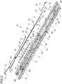
- Fig. 1 is a perspective view of a bus bar module and a battery assembly body according to the present embodiment.
- a bus bar module 10 is assembled to an upper portion of a battery assembly body 1 to constitute a power supply apparatus 2.
- the power supply apparatus 2 is used by being mounted on various vehicles such as an electric automobile that travels using an electric motor and a hybrid automobile that travels using an engine and an electric motor in combination, and supplies power to the electric motor.
- the battery assembly body 1 includes a plurality of electric cells 3 arranged in a row along one direction.
- Each electric cell 3 is formed in a rectangular parallelepiped shape, and includes a pair of electrodes 5 provided so as to protrude from one end and the other end of an upper surface, respectively.
- One of the pair of electrodes 5 is a positive electrode, and the other of the pair of electrodes 5 is a negative electrode.
- the plurality of (four in this example) electric cells 3 adjacent to each other are set as one set, and electrodes of the electrodes 5 are aligned.
- the bus bar module 10 connects sets of the electric cells 3 in series by bus bars 50 to be described later.
- Fig. 2 is an exploded perspective view of the bus bar module according to the present embodiment.
- the bus bar module 10 includes a case 20, the bus bars 50, and a wire harness 60 including a plurality of electric wires 61.
- the case 20 is formed of, for example, an electrically insulating synthetic resin or the like, and includes a plurality of bus bar housing portions 21.
- the bus bar housing portions 21 are arranged in two rows along an arrangement direction of the plurality of electric cells 3.
- the bus bar housing portion 21 is formed in a frame shape, and the bus bar 50 is housed in the bus bar housing portion 21.
- a first electric wire routing groove portion 31A and a second electric wire routing groove portion 31B are provided between the two rows of bus bar housing portions 21.
- the first electric wire routing groove portion 31A and the second electric wire routing groove portion 31B are formed along the rows of the bus bar housing portions 21 in a longitudinal direction of the case 20.
- a first electric wire bridge portion 33A, a second electric wire bridge portion 33B, and a third electric wire bridge portion 33C are provided between the first electric wire routing groove portion 31A and the second electric wire routing groove portion 31B.
- the first electric wire bridge portion 33A is provided in the vicinity of one end 20A of the case 20, the second electric wire bridge portion 33B is provided in the middle of the case 20, and the third electric wire bridge portion 33C is provided in the vicinity of the other end 20B of the case 20.
- a cover 25 is attached to the case 20 from above. When being attached to the case 20, the cover 25 covers the first electric wire routing groove portion 31A, the second electric wire routing groove portion 31B, the first electric wire bridge portion 33A, the second electric wire bridge portion 33B, and the third electric wire bridge portion 33C.
- the case 20 includes an electric wire take-out portion 35.
- the electric wire take-out portion 35 is provided between the first electric wire bridge portion 33A and the second electric wire bridge portion 33B of the first electric wire routing groove portion 31A.
- An electric wire pressing cover 36 can be attached to the electric wire take-out portion 35 from above.
- the plurality of electric wires 61 that constitute the wire harness 60 are electric wires for voltage detection with connection terminals 62 connected to end portions, and electric wires for temperature measurement with thermistors 63 connected to the end portions.
- the connection terminals 62 are fastened together with the respective bus bars 50 to the electrodes 5 of the electric cells 3, and are electrically connected to the bus bars 50.
- the thermistor 63 is in contact with a specific electric cell 3 of the battery assembly body 1 to measure a temperature of the electric cell 3.
- the electric wires 61 are connected to a control circuit substrate (not shown) including a voltage monitoring circuit and a temperature monitoring circuit.
- the electric wires 61 of the wire harness 60 are housed and routed in the first electric wire routing groove portion 31A, the second electric wire routing groove portion 31B, the first electric wire bridge portion 33A, the second electric wire bridge portion 33B, and the third electric wire bridge portion 33C. Then, the electric wires 61 are pulled out to an outside from the electric wire take-out portion 35 provided in the first electric wire routing groove portion 31A.
- the case 20 that constitutes the bus bar module 10 is divided at a substantially middle portion in the longitudinal direction. Accordingly, the case 20 includes two divided cases 22 and 23 divided in the longitudinal direction. These divided cases 22 and 23 are coupled to each other to constitute the case 20. These divided cases 22 and 23 may be called as a first divided case 22 and a second divided case 23, respectively. Hereinafter, it is referred to as the divided cases 22 and 23.
- Fig. 3 is a perspective view of coupling locations between the divided cases.
- Fig. 4 is a perspective view of a first coupling portion and a second coupling portion of the divided cases.
- Figs. 5A and 5B are views showing a female lock portion and a male lock portion that constitute the first coupling portion of the divided cases.
- Fig. 5A is a plan view, and Fig. 5B is a cross-sectional view taken along a line A-A in Fig. 5A .
- the divided cases 22 and 23 coupled to each other include first coupling portions 41 and second coupling portions 45.
- the first coupling portion 41 includes a female lock portion 42 provided at an end portion of the bus bar housing portion 21 of one divided case 22 and a male lock portion 43 provided at an end portion of the bus bar housing portion 21 of the other divided case 23.
- the female lock portion 42 is provided on an end surface 21a of the bus bar housing portion 21 of one divided case 22.
- the female lock portion 42 includes a locking frame 71. Both end portions of the locking frame 71 are supported by the end surface 21a via fixing portions 71a, the locking frame 71 is formed in a box shape in which an upper portion is opened, and the locking frame 71 is disposed in parallel to the end surface 21a with a gap G.
- the end surface 21a includes support portions 72 on both sides of the locking frame 71. These support portions 72 protrude from the end surface 21a, and upper surfaces of the support portions 72 are abutment surfaces 72a formed of horizontal surfaces.
- the female lock portion 42 includes housing recesses 73 on lower sides of the support portions 72 on both sides of the locking frame 71.
- the housing recesses 73 are provided at positions facing elastic arms 75 of the male lock portion 43, which will be described later, when the housing recesses 73 are coupled to the male lock portion 43.
- the female lock portion 42 includes side walls 74 on both side portions thereof.
- the male lock portion 43 is provided on an end surface 21b of the bus bar housing portion 21 of the other divided case 23.
- the male lock portion 43 includes the pair of elastic arms 75 formed in a belt shape.
- One end of the elastic arm 75 is continuously provided to a vicinity of a lower end of the end surface 21b.
- the elastic arms 75 are bent upward from one end side and are extended, and the other ends are bent in a direction away from the end surface 21b.
- the other ends of these elastic arms 75 are continuously provided to a support plate portion 76.
- the support plate portion 76 is supported by the elastic arms 75 and is disposed along a horizontal direction.
- a locking plate portion 77 that extends downward is integrally formed at a middle portion of the support plate portion 76.
- a lock claw 78 protrudes from a surface of the locking plate portion 77 on an end surface 21b side at a lower end of the locking plate portion 77. Further, a pair of slits 79 are formed in the support plate portion 76 of the male lock portion 43. These slits 79 are formed on an elastic arm 75 side. Accordingly, in the male lock portion 43, since the slits 79 are provided between the locking plate portion 77 and the elastic arms 75, the elastic arms 75 are arranged at positions away from the locking plate portion 77.
- the second coupling portion 45 includes female lock portions 46 provided at end portions of the first electric wire routing groove portion 31A and the second electric wire routing groove portion 31B of one divided case 22, and male lock portions 47 provided at end portions of the first electric wire routing groove portion 31A and the second electric wire routing groove portion 31B of the other divided case 23.
- the female lock portion 46 includes an engagement recess 81 open upward and forward. Locking claws 82 that protrude inward are formed on both side walls 81a of the engagement recess 81. Further, an engagement protrusion 83 that protrudes upward is formed on a bottom wall 81b of the engagement recess 81.
- the male lock portion 47 includes an engagement plate portion 85 formed in a flat plate shape.
- the engagement plate portion 85 has a width dimension that allows the engagement plate portion 85 to be fitted into the engagement recess 81 of the female lock portion 46.
- An engagement hole portion 86 formed of a long hole is formed along a longitudinal direction in a central portion in a width direction of the engagement plate portion 85.
- Figs. 6A to 6C are views showing the female lock portion and the male lock portion that constitute the first coupling portion of the divided cases in a coupled state.
- Fig. 6A is a plan view
- Fig. 6B is a cross-sectional view taken along a line B-B in Fig. 6A
- Fig. 6C is a cross-sectional view taken along a line C-C in Fig. 6A .
- the female lock portion 42 and the male lock portion 43 of the first coupling portion 41 are engaged with each other, and the female lock portion 46 and the male lock portion 47 of the second coupling portion 45 are engaged with each other.
- the locking plate portion 77 of the male lock portion 43 is inserted into the gap G between the end surface 21a and the locking frame 71 of the female lock portion 42 from above. Then, the lock claw 78 of the locking plate portion 77 inserted into the gap G locks a lower edge of the locking frame 71. Accordingly, the female lock portion 42 and the male lock portion 43 are engaged with each other. In this engaged state, the support plate portion 76 of the male lock portion 43 abuts against the abutment surface 72a of the support portion 72 of the female lock portion 42.
- the elastic arms 75 of the male lock portion 43 are arranged at positions facing the housing recesses 73 of the female lock portion 42. Further, in a state where the lock claw 78 of the locking plate portion 77 of the male lock portion 43 is locked to the locking frame 71 of the female lock portion 42, the male lock portion 43 is fitted between the side walls 74 of the female lock portion 42.
- the engagement plate portion 85 of the male lock portion 47 is fitted into the engagement recess 81 of the female lock portion 46 from above. Then, the engagement protrusion 83 is inserted into the engagement hole portion 86 of the engagement plate portion 85 fitted into the engagement recess 81, and both side portions of the engagement plate portion 85 are locked by the locking claws 82. In this state, the engagement plate portion 85 is fitted between the side walls 81a of the engagement recess 81.
- the divided cases 22 and 23 are coupled to each other by the first coupling portion 41 and the second coupling portion 45 to form the case 20.
- bus bar module according to a reference example not according to the invention.
- divided cases 101A and 101B are coupled to each other by a pair of coupling portions 103 arranged in a width direction.
- the coupling portion 103 includes a female lock portion 111 provided at an end portion of one divided case 101A and a male lock portion 115 provided at an end portion of the other divided case 101B.
- the female lock portion 111 includes a coupling plate portion 113 including a long hole 112, on an end surface of one divided case 101A.
- the male lock portion 115 includes a pair of elastic arms 116 that extend from an end surface of the other divided case 101B.
- a support portion 117 including a peripheral wall 117a is continuously provided at a tip end of the elastic arm 116, and a locking plate portion 119 including a locking claw 118 protrudes downward from the support portion 117.
- the locking plate portion 119 of the male lock portion 115 is inserted into the long hole 112 of the coupling plate portion 113 of the female lock portion 111, so that the locking claw 118 of the locking plate portion 119 locks an edge portion of the long hole 112 of the coupling plate portion 113. Accordingly, the female lock portion 111 and the male lock portion 115 are engaged with each other, and the divided cases 101A and 101B are coupled to each other.
- the male lock portion 115 in the male lock portion 115, the locking plate portion 119 including the locking claw 118 is provided on the support portion 117 including the peripheral wall 117a. Therefore, the male lock portion 115 has high rigidity, and tolerance absorbing performance of the coupling portion 103 is not good. Further, in the male lock portion 115, the elastic arms 116 provided adjacent to the locking plate portion 119 abut against the coupling plate portion 113 of the female lock portion 111, and thus elastic deformation is restricted. Therefore, it is difficult for the coupling portion 103 to sufficiently absorb a tolerance.
- the slits 79 are formed in the support plate portion 76 of the male lock portion 43 of the first coupling portion 41 on the elastic arm 75 side of the locking plate portion 77. Therefore, rigidity of the support plate portion 76 of the male lock portion 43 can be reduced. Accordingly, a tolerance of an arrangement pitch of the electrodes 5 of the electric cells 3 can be sufficiently absorbed in the first coupling portions 41 of the divided cases 22 and 23, and the bus bar module 10 can be favorably and smoothly assembled to the battery assembly body 1.
- the female lock portion 42 includes the housing recesses 73 that can house the elastically deformed elastic arms 75 at the positions facing the elastic arms 75 on both sides of the locking frame 71.
- the slits 79 are provided between the locking plate portion 77 and the elastic arms 75, so that the elastic arms 75 are arranged at the positions away from the locking plate portion 77.
- the housing recesses 73 can be easily provided at the positions facing the elastic arms 75 on both sides of the locking frame 71.
- the elastic arms 75 are housed in the housing recesses 73. Therefore, it is possible to expand an absorption range of a tolerance at the first coupling portions 41 between the divided cases 22 and 23, and it is possible to more favorably and smoothly assemble the bus bar module 10 to the battery assembly body 1.
- the second coupling portion 45 is provided at a position adjacent to the first coupling portion 41 in a width direction of the case 20. Accordingly, the second coupling portion 45 is disposed at a position close to the first coupling portion 41, and twisting of the divided cases 22 and 23 in a planar direction in the first coupling portion 41 that couples the bus bar housing portions 21 to each other can be effectively prevented by the second coupling portion 45. Therefore, it is possible to prevent a positional deviation of the bus bars 50 housed in the bus bar housing portions 21 with respect to the electrodes 5 of the electric cells 3 that constitute the battery assembly body 1, and thus it is possible to favorably and smoothly assemble the bus bar module 10 to the battery assembly body 1.
- the male lock portion 43 is fitted between the side walls 74 of the female lock portion 42, and in the second coupling portion 45, the male lock portion 47 is fitted between the side walls 81a of the female lock portion 46. Accordingly, if the divided cases 22 and 23 are twisted in the planar direction, the male lock portion 43 abuts against the side walls 74, and the male lock portion 47 abuts against the side walls 81a, so that the twisting of the divided cases 22 and 23 in the planar direction is prevented. Therefore, the bus bar module 10 can be more favorably assembled to the battery assembly body 1.
- a bus bar module (10) includes: a case (20) assembled to a battery assembly body (1) including a plurality of electric cells (3); and a bus bar (50) supported in the case (20) and connected to electrodes (5) of the electric cells (3) of the battery assembly body (1).
- the case (20) includes a coupling portion (a first coupling portion 41), a first divided case (22) and a second divided case (23) which are divided in an arrangement direction of the electric cells (3) and coupled at the coupling portion (the first coupling portion 41), the coupling portion (the first coupling portion 41) including a female lock portion (42) provided at the first divided case (22) and a male lock portion (43) provided at the second divided case (23).
- the female lock portion (42) includes a locking frame (71) provided with a gap (G) spaced apart from an end surface (21a) of the first divided case (22).
- the male lock portion (43) includes a pair of elastic arms (75) extending from an end surface (21b) of the second divided case (23) and having at least two bending points, a support plate portion (76) spanning end portions of the elastic arms (75) between each other, a locking plate portion (77) formed on the support plate portion (76) and inserted into the gap (G) of the female lock portion (42), and a lock claw (78) provided on the locking plate portion (77) and locking the locking frame (71) by inserting the locking plate portion (77) into the gap (G).
- the support plate portion (76) of the male lock portion (43) has slits (79) at a side of the elastic arms (75).
- the locking plate portion of the male lock portion is inserted into the gap between the end surface and the locking frame of the female lock portion, so that the lock claw of the locking plate portion locks the locking frame. Accordingly, the divided cases can be easily coupled to each other by the coupling portion including the female lock portion and the male lock portion. Further, the slits are formed in the support plate portion of the male lock portion on the elastic arm side of the locking plate portion. Therefore, rigidity of the support plate portion of the male lock portion can be reduced. Accordingly, a tolerance of an arrangement pitch of the electrodes of the electric cells can be sufficiently absorbed by the coupling portion between the divided cases, and the bus bar module can be favorably and smoothly assembled to the battery assembly body.
- the female lock portion (42) includes housing recesses (73) being capable of housing the elastic arms (75) deformed elastically at positions in both sides of the locking frame (71) at which the housing recesses (73) and the elastic arms (75) face with each other.
- the elastic arms when the elastic arms are elastically deformed toward a female lock portion side, the elastic arms are housed in the housing recesses provided at the positions facing the elastic arms on both sides of the locking frame of the female lock portion. Accordingly, it is possible to expand an absorption range of a tolerance at the coupling portion between the divided cases, and it is possible to more favorably and smoothly assemble the bus bar module to the battery assembly body.
- the female lock portion (42) includes an abutment surface (72a) against which the support plate portion (76) of the male lock portion (43) abuts in a state where the lock claw (78) locks the locking frame (71).
- the support plate portion of the male lock portion abuts against the abutment surface of the female lock portion. Accordingly, it is possible to prevent twisting between the divided cases with a longitudinal direction as an axis, and it is possible to more favorably assemble the bus bar module to the battery assembly body.
- the coupling portion is a first coupling portion (41) provided between bus bar housing portions (21) in which the bus bar (50) is housed.
- the case (20) further includes a second coupling portion (45) in which a male lock portion (47) is engaged with a female lock portion (46) between electric wire routing groove portions (a first electric wire routing groove portion 31A, and a second electric wire routing groove portion 31B) in which an electric wire (61) is routed.
- the second coupling portion (45) is provided at a position adjacent to the first coupling portion (41) in a width direction of the case (20).
- the second coupling portion that couples the electric wire routing groove portions to each other is preferably provided at the position adjacent to the first coupling portion that couples the bus bar housing portions of the divided cases to each other in the width direction of the case. Accordingly, the second coupling portion is disposed at a position close to the first coupling portion, and in the first coupling portion that couples the bus bar housing portions to each other, it is possible to effectively prevent twisting of the divided cases in a planar direction by the second coupling portion. Therefore, it is possible to prevent a positional deviation of the bus bars housed in the bus bar housing portions with respect to the electrodes of the electric cells that constitute the battery assembly body, and thus it is possible to favorably and smoothly assemble the bus bar module to the battery assembly body.
- the female lock portion (42, 46) in at least one of the first coupling portion (41) and the second coupling portion (45), includes side walls (74, 81a) facing each other and spaced apart in the width direction of the case (20), and the male lock portion (43, 47) is fitted between the side walls (74, 81a) of the female lock portion (42, 46).
- the male lock portion is fitted between the side walls provided at the female lock portion. Accordingly, it is possible to prevent the twisting of the divided cases in the planar direction, and it is possible to more favorably assemble the bus bar module to the battery assembly body.
- a bus bar module that can sufficiently absorb a tolerance of electrodes of electric cells that constitute a battery assembly body and can be favorably assembled to the battery assembly body.
Description
- The present disclosure relates to a bus bar module.
- A power supply apparatus mounted on various vehicles such as an electric automobile that travels using an electric motor and a hybrid automobile that travels using an engine and an electric motor in combination has a bus bar module assembled on an upper portion of a battery assembly body including a plurality of electric cells. The bus bar module includes a plurality of bus bars electrically connected to electrodes of the plurality of electric cells. These bus bars are housed and held in a resin-made case attached to the upper portion of the battery assembly body (see, for example,
JP2012-164591A - Another example od the prior art can be seen in document
JP 2015 133 233 A JP 2015 133 233 A - Some bus bar modules include a case in which a plurality of divided cases are coupled to each other. In such a case, a coupling portion between the divided cases absorbs a tolerance of an arrangement pitch of electrodes of electric cells.
- However, when the arrangement pitch of the electrodes of the electric cells that constitute the battery assembly body is narrowed, a space that can be secured for tolerance absorption at the coupling portion of the divided cases becomes small. Then, a tolerance cannot be sufficiently absorbed in the coupling portion of the divided cases, and it may be difficult to assemble the bus bar module to the battery assembly body.
- The present disclosure provides a bus bar module that can sufficiently absorb a tolerance of electrodes of electric cells that constitute a battery assembly body and can be favorably assembled to the battery assembly body.
- According to the present invention, a bus bar module including the features of
claim 1 is provided. - The present disclosure has been briefly described above. Details of the present disclosure are further clarified by reading a mode for carrying out the disclosure (hereinafter, referred to as "embodiment") described below with reference to attached drawings.
-
-
Fig. 1 is a perspective view of a bus bar module and a battery assembly body according to the present embodiment. -
Fig. 2 is an exploded perspective view of the bus bar module according to the present embodiment. -
Fig. 3 is a perspective view of coupling locations between divided cases. -
Fig. 4 is a perspective view of a first coupling portion and a second coupling portion of the divided cases. -
Fig. 5A is a plan view showing a female lock portion and a male lock portion that constitute the first coupling portion of the divided cases. -
Fig. 5B is a cross-sectional view taken along a line A-A inFig. 5A . -
Fig. 6A is a plan view showing the female lock portion and the male lock portion that constitute the first coupling portion of the divided cases in a coupled state. -
Fig. 6B is a cross-sectional view taken along a line B-B inFig. 6A . -
Fig. 6C is a cross-sectional view taken along a line C-C inFig. 6A . -
Fig. 7 is a plan view of coupling locations between divided cases that constitute a case of a bus bar module according to a reference example not according to the invention. -
Fig. 8 is a perspective view of the coupling locations between the divided cases that constitute the case of the bus bar module according to the reference example. -
Fig. 9A is a plan view showing a female lock portion and a male lock portion that constitute a coupling portion in the reference example. -
Fig. 9B is a cross-sectional view taken along a line D-D inFig. 9A . -
Fig. 10 is a perspective view seen from a lower side of the male lock portion that constitutes the coupling portion in the reference example. -
Fig. 11A is a plan view showing the female lock portion and the male lock portion that constitute the coupling portion of the divided cases in a coupled state in the reference example. -
Fig. 11B is a cross-sectional view taken along a line E-E inFig. 11A . - Hereinafter, an example of an embodiment according to the present invention will be described with reference to the drawings.
-
Fig. 1 is a perspective view of a bus bar module and a battery assembly body according to the present embodiment. - As shown in
Fig. 1 , abus bar module 10 according to the present embodiment is assembled to an upper portion of abattery assembly body 1 to constitute apower supply apparatus 2. Thepower supply apparatus 2 is used by being mounted on various vehicles such as an electric automobile that travels using an electric motor and a hybrid automobile that travels using an engine and an electric motor in combination, and supplies power to the electric motor. - The
battery assembly body 1 includes a plurality ofelectric cells 3 arranged in a row along one direction. Eachelectric cell 3 is formed in a rectangular parallelepiped shape, and includes a pair ofelectrodes 5 provided so as to protrude from one end and the other end of an upper surface, respectively. One of the pair ofelectrodes 5 is a positive electrode, and the other of the pair ofelectrodes 5 is a negative electrode. - In the
battery assembly body 1, the plurality of (four in this example)electric cells 3 adjacent to each other are set as one set, and electrodes of theelectrodes 5 are aligned. Thebus bar module 10 connects sets of theelectric cells 3 in series bybus bars 50 to be described later. -
Fig. 2 is an exploded perspective view of the bus bar module according to the present embodiment. - As shown in
Fig. 2 , thebus bar module 10 includes acase 20, thebus bars 50, and awire harness 60 including a plurality ofelectric wires 61. - The
case 20 is formed of, for example, an electrically insulating synthetic resin or the like, and includes a plurality of busbar housing portions 21. - The bus
bar housing portions 21 are arranged in two rows along an arrangement direction of the plurality ofelectric cells 3. The busbar housing portion 21 is formed in a frame shape, and thebus bar 50 is housed in the busbar housing portion 21. - A first electric wire
routing groove portion 31A and a second electric wirerouting groove portion 31B are provided between the two rows of busbar housing portions 21. The first electric wirerouting groove portion 31A and the second electric wirerouting groove portion 31B are formed along the rows of the busbar housing portions 21 in a longitudinal direction of thecase 20. Further, a first electricwire bridge portion 33A, a second electricwire bridge portion 33B, and a third electricwire bridge portion 33C are provided between the first electric wirerouting groove portion 31A and the second electric wirerouting groove portion 31B. - The first electric
wire bridge portion 33A is provided in the vicinity of oneend 20A of thecase 20, the second electricwire bridge portion 33B is provided in the middle of thecase 20, and the third electricwire bridge portion 33C is provided in the vicinity of theother end 20B of thecase 20. As shown inFig. 1 , acover 25 is attached to thecase 20 from above. When being attached to thecase 20, thecover 25 covers the first electric wirerouting groove portion 31A, the second electric wirerouting groove portion 31B, the first electricwire bridge portion 33A, the second electricwire bridge portion 33B, and the third electricwire bridge portion 33C. - The
case 20 includes an electric wire take-outportion 35. The electric wire take-outportion 35 is provided between the first electricwire bridge portion 33A and the second electricwire bridge portion 33B of the first electric wirerouting groove portion 31A. An electricwire pressing cover 36 can be attached to the electric wire take-outportion 35 from above. - As shown in
Fig. 2 , the plurality ofelectric wires 61 that constitute thewire harness 60 are electric wires for voltage detection withconnection terminals 62 connected to end portions, and electric wires for temperature measurement withthermistors 63 connected to the end portions. Theconnection terminals 62 are fastened together with therespective bus bars 50 to theelectrodes 5 of theelectric cells 3, and are electrically connected to the bus bars 50. Further, thethermistor 63 is in contact with a specificelectric cell 3 of thebattery assembly body 1 to measure a temperature of theelectric cell 3. In thewire harness 60, theelectric wires 61 are connected to a control circuit substrate (not shown) including a voltage monitoring circuit and a temperature monitoring circuit. - The
electric wires 61 of thewire harness 60 are housed and routed in the first electric wirerouting groove portion 31A, the second electric wirerouting groove portion 31B, the first electricwire bridge portion 33A, the second electricwire bridge portion 33B, and the third electricwire bridge portion 33C. Then, theelectric wires 61 are pulled out to an outside from the electric wire take-outportion 35 provided in the first electric wirerouting groove portion 31A. - The
case 20 that constitutes thebus bar module 10 is divided at a substantially middle portion in the longitudinal direction. Accordingly, thecase 20 includes two dividedcases cases case 20. These dividedcases case 22 and a second dividedcase 23, respectively. Hereinafter, it is referred to as the dividedcases - Next, a coupling structure between the divided
cases -
Fig. 3 is a perspective view of coupling locations between the divided cases.Fig. 4 is a perspective view of a first coupling portion and a second coupling portion of the divided cases.Figs. 5A and 5B are views showing a female lock portion and a male lock portion that constitute the first coupling portion of the divided cases.Fig. 5A is a plan view, andFig. 5B is a cross-sectional view taken along a line A-A inFig. 5A . - As shown in
Fig. 3 , the dividedcases first coupling portions 41 andsecond coupling portions 45. - The
first coupling portion 41 includes afemale lock portion 42 provided at an end portion of the busbar housing portion 21 of one dividedcase 22 and amale lock portion 43 provided at an end portion of the busbar housing portion 21 of the other dividedcase 23. - As shown in
Figs. 4 ,5A, and 5B , thefemale lock portion 42 is provided on anend surface 21a of the busbar housing portion 21 of one dividedcase 22. Thefemale lock portion 42 includes a lockingframe 71. Both end portions of the lockingframe 71 are supported by theend surface 21a via fixingportions 71a, the lockingframe 71 is formed in a box shape in which an upper portion is opened, and the lockingframe 71 is disposed in parallel to theend surface 21a with a gap G. Further, theend surface 21a includessupport portions 72 on both sides of the lockingframe 71. Thesesupport portions 72 protrude from theend surface 21a, and upper surfaces of thesupport portions 72 areabutment surfaces 72a formed of horizontal surfaces. Further, thefemale lock portion 42 includeshousing recesses 73 on lower sides of thesupport portions 72 on both sides of the lockingframe 71. The housing recesses 73 are provided at positions facingelastic arms 75 of themale lock portion 43, which will be described later, when thehousing recesses 73 are coupled to themale lock portion 43. Further, thefemale lock portion 42 includesside walls 74 on both side portions thereof. - The
male lock portion 43 is provided on anend surface 21b of the busbar housing portion 21 of the other dividedcase 23. Themale lock portion 43 includes the pair ofelastic arms 75 formed in a belt shape. One end of theelastic arm 75 is continuously provided to a vicinity of a lower end of theend surface 21b. Theelastic arms 75 are bent upward from one end side and are extended, and the other ends are bent in a direction away from theend surface 21b. The other ends of theseelastic arms 75 are continuously provided to asupport plate portion 76. Thesupport plate portion 76 is supported by theelastic arms 75 and is disposed along a horizontal direction. A lockingplate portion 77 that extends downward is integrally formed at a middle portion of thesupport plate portion 76. Alock claw 78 protrudes from a surface of the lockingplate portion 77 on anend surface 21b side at a lower end of the lockingplate portion 77. Further, a pair ofslits 79 are formed in thesupport plate portion 76 of themale lock portion 43. Theseslits 79 are formed on anelastic arm 75 side. Accordingly, in themale lock portion 43, since theslits 79 are provided between the lockingplate portion 77 and theelastic arms 75, theelastic arms 75 are arranged at positions away from the lockingplate portion 77. - As shown in
Figs. 3 and4 , thesecond coupling portion 45 includesfemale lock portions 46 provided at end portions of the first electric wirerouting groove portion 31A and the second electric wirerouting groove portion 31B of one dividedcase 22, andmale lock portions 47 provided at end portions of the first electric wirerouting groove portion 31A and the second electric wirerouting groove portion 31B of the other dividedcase 23. - The
female lock portion 46 includes anengagement recess 81 open upward and forward. Lockingclaws 82 that protrude inward are formed on bothside walls 81a of theengagement recess 81. Further, anengagement protrusion 83 that protrudes upward is formed on abottom wall 81b of theengagement recess 81. - The
male lock portion 47 includes anengagement plate portion 85 formed in a flat plate shape. Theengagement plate portion 85 has a width dimension that allows theengagement plate portion 85 to be fitted into theengagement recess 81 of thefemale lock portion 46. Anengagement hole portion 86 formed of a long hole is formed along a longitudinal direction in a central portion in a width direction of theengagement plate portion 85. - Next, a case where the
case 20 is formed by coupling the dividedcases -
Figs. 6A to 6C are views showing the female lock portion and the male lock portion that constitute the first coupling portion of the divided cases in a coupled state.Fig. 6A is a plan view,Fig. 6B is a cross-sectional view taken along a line B-B inFig. 6A, and Fig. 6C is a cross-sectional view taken along a line C-C inFig. 6A . - In order to couple the divided
cases female lock portion 42 and themale lock portion 43 of thefirst coupling portion 41 are engaged with each other, and thefemale lock portion 46 and themale lock portion 47 of thesecond coupling portion 45 are engaged with each other. - As shown in
Figs. 6A, 6B, and 6C , in thefirst coupling portion 41, the lockingplate portion 77 of themale lock portion 43 is inserted into the gap G between theend surface 21a and the lockingframe 71 of thefemale lock portion 42 from above. Then, thelock claw 78 of the lockingplate portion 77 inserted into the gap G locks a lower edge of the lockingframe 71. Accordingly, thefemale lock portion 42 and themale lock portion 43 are engaged with each other. In this engaged state, thesupport plate portion 76 of themale lock portion 43 abuts against theabutment surface 72a of thesupport portion 72 of thefemale lock portion 42. Further, theelastic arms 75 of themale lock portion 43 are arranged at positions facing thehousing recesses 73 of thefemale lock portion 42. Further, in a state where thelock claw 78 of the lockingplate portion 77 of themale lock portion 43 is locked to the lockingframe 71 of thefemale lock portion 42, themale lock portion 43 is fitted between theside walls 74 of thefemale lock portion 42. - In the
second coupling portion 45, theengagement plate portion 85 of themale lock portion 47 is fitted into theengagement recess 81 of thefemale lock portion 46 from above. Then, theengagement protrusion 83 is inserted into theengagement hole portion 86 of theengagement plate portion 85 fitted into theengagement recess 81, and both side portions of theengagement plate portion 85 are locked by the lockingclaws 82. In this state, theengagement plate portion 85 is fitted between theside walls 81a of theengagement recess 81. - Accordingly, the divided
cases first coupling portion 41 and thesecond coupling portion 45 to form thecase 20. - Here, a bus bar module according to a reference example not according to the invention will be described
- As shown in
Figs. 7 ,8 ,9A, and 9B , in abus bar module 100 according to the reference example, dividedcases coupling portions 103 arranged in a width direction. - The
coupling portion 103 includes afemale lock portion 111 provided at an end portion of one dividedcase 101A and amale lock portion 115 provided at an end portion of the other dividedcase 101B. - The
female lock portion 111 includes acoupling plate portion 113 including along hole 112, on an end surface of one dividedcase 101A. Themale lock portion 115 includes a pair ofelastic arms 116 that extend from an end surface of the other dividedcase 101B. As shown inFig. 10 , asupport portion 117 including aperipheral wall 117a is continuously provided at a tip end of theelastic arm 116, and alocking plate portion 119 including a lockingclaw 118 protrudes downward from thesupport portion 117. - As shown in
Figs. 11A and 11B , in thecoupling portion 103, the lockingplate portion 119 of themale lock portion 115 is inserted into thelong hole 112 of thecoupling plate portion 113 of thefemale lock portion 111, so that the lockingclaw 118 of the lockingplate portion 119 locks an edge portion of thelong hole 112 of thecoupling plate portion 113. Accordingly, thefemale lock portion 111 and themale lock portion 115 are engaged with each other, and the dividedcases - In the
bus bar module 100 according to the reference example, in themale lock portion 115, the lockingplate portion 119 including the lockingclaw 118 is provided on thesupport portion 117 including theperipheral wall 117a. Therefore, themale lock portion 115 has high rigidity, and tolerance absorbing performance of thecoupling portion 103 is not good. Further, in themale lock portion 115, theelastic arms 116 provided adjacent to thelocking plate portion 119 abut against thecoupling plate portion 113 of thefemale lock portion 111, and thus elastic deformation is restricted. Therefore, it is difficult for thecoupling portion 103 to sufficiently absorb a tolerance. - Therefore, in the
bus bar module 100 according to the reference example, when an arrangement pitch of theelectrodes 5 of theelectric cells 3 that constitute thebattery assembly body 1 is narrowed, and thus a space that can be secured for tolerance absorption of thecoupling portion 103 is reduced, a tolerance cannot be sufficiently absorbed in thecoupling portion 103, and it may be difficult to assemble thebus bar module 100 to thebattery assembly body 1. - On the contrary, according to the
bus bar module 10 of the present embodiment, theslits 79 are formed in thesupport plate portion 76 of themale lock portion 43 of thefirst coupling portion 41 on theelastic arm 75 side of the lockingplate portion 77. Therefore, rigidity of thesupport plate portion 76 of themale lock portion 43 can be reduced. Accordingly, a tolerance of an arrangement pitch of theelectrodes 5 of theelectric cells 3 can be sufficiently absorbed in thefirst coupling portions 41 of the dividedcases bus bar module 10 can be favorably and smoothly assembled to thebattery assembly body 1. - Further, the
female lock portion 42 includes thehousing recesses 73 that can house the elastically deformedelastic arms 75 at the positions facing theelastic arms 75 on both sides of the lockingframe 71. Here, in themale lock portion 43, theslits 79 are provided between the lockingplate portion 77 and theelastic arms 75, so that theelastic arms 75 are arranged at the positions away from the lockingplate portion 77. Accordingly, in thefemale lock portion 42, thehousing recesses 73 can be easily provided at the positions facing theelastic arms 75 on both sides of the lockingframe 71. Then, by providing thehousing recesses 73 in thefemale lock portion 42, when theelastic arms 75 are elastically deformed toward afemale lock portion 42 side, theelastic arms 75 are housed in the housing recesses 73. Therefore, it is possible to expand an absorption range of a tolerance at thefirst coupling portions 41 between the dividedcases bus bar module 10 to thebattery assembly body 1. - Further, when the
lock claw 78 of the lockingplate portion 77 of themale lock portion 43 is locked to the lockingframe 71 of thefemale lock portion 42, thesupport plate portion 76 of themale lock portion 43 abuts against the abutment surfaces 72a of thefemale lock portion 42. Accordingly, it is possible to prevent twisting between the dividedcases bus bar module 10 to thebattery assembly body 1. - The
second coupling portion 45 is provided at a position adjacent to thefirst coupling portion 41 in a width direction of thecase 20. Accordingly, thesecond coupling portion 45 is disposed at a position close to thefirst coupling portion 41, and twisting of the dividedcases first coupling portion 41 that couples the busbar housing portions 21 to each other can be effectively prevented by thesecond coupling portion 45. Therefore, it is possible to prevent a positional deviation of the bus bars 50 housed in the busbar housing portions 21 with respect to theelectrodes 5 of theelectric cells 3 that constitute thebattery assembly body 1, and thus it is possible to favorably and smoothly assemble thebus bar module 10 to thebattery assembly body 1. - Further, in the
first coupling portion 41, themale lock portion 43 is fitted between theside walls 74 of thefemale lock portion 42, and in thesecond coupling portion 45, themale lock portion 47 is fitted between theside walls 81a of thefemale lock portion 46. Accordingly, if the dividedcases male lock portion 43 abuts against theside walls 74, and themale lock portion 47 abuts against theside walls 81a, so that the twisting of the dividedcases bus bar module 10 can be more favorably assembled to thebattery assembly body 1. - According to the present invention, a bus bar module (10) includes:
a case (20) assembled to a battery assembly body (1) including a plurality of electric cells (3); and a bus bar (50) supported in the case (20) and connected to electrodes (5) of the electric cells (3) of the battery assembly body (1). The case (20) includes a coupling portion (a first coupling portion 41), a first divided case (22) and a second divided case (23) which are divided in an arrangement direction of the electric cells (3) and coupled at the coupling portion (the first coupling portion 41), the coupling portion (the first coupling portion 41) including a female lock portion (42) provided at the first divided case (22) and a male lock portion (43) provided at the second divided case (23). The female lock portion (42) includes a locking frame (71) provided with a gap (G) spaced apart from an end surface (21a) of the first divided case (22). The male lock portion (43) includes a pair of elastic arms (75) extending from an end surface (21b) of the second divided case (23) and having at least two bending points, a support plate portion (76) spanning end portions of the elastic arms (75) between each other, a locking plate portion (77) formed on the support plate portion (76) and inserted into the gap (G) of the female lock portion (42), and a lock claw (78) provided on the locking plate portion (77) and locking the locking frame (71) by inserting the locking plate portion (77) into the gap (G). The support plate portion (76) of the male lock portion (43) has slits (79) at a side of the elastic arms (75). - According to the bus bar module of the invention, the locking plate portion of the male lock portion is inserted into the gap between the end surface and the locking frame of the female lock portion, so that the lock claw of the locking plate portion locks the locking frame. Accordingly, the divided cases can be easily coupled to each other by the coupling portion including the female lock portion and the male lock portion. Further, the slits are formed in the support plate portion of the male lock portion on the elastic arm side of the locking plate portion. Therefore, rigidity of the support plate portion of the male lock portion can be reduced. Accordingly, a tolerance of an arrangement pitch of the electrodes of the electric cells can be sufficiently absorbed by the coupling portion between the divided cases, and the bus bar module can be favorably and smoothly assembled to the battery assembly body.
- According to a preferred aspect of the present invention, the female lock portion (42) includes housing recesses (73) being capable of housing the elastic arms (75) deformed elastically at positions in both sides of the locking frame (71) at which the housing recesses (73) and the elastic arms (75) face with each other.
- According to the bus bar module of the preferred aspect, when the elastic arms are elastically deformed toward a female lock portion side, the elastic arms are housed in the housing recesses provided at the positions facing the elastic arms on both sides of the locking frame of the female lock portion. Accordingly, it is possible to expand an absorption range of a tolerance at the coupling portion between the divided cases, and it is possible to more favorably and smoothly assemble the bus bar module to the battery assembly body.
- According to a preferred aspect of the present invention, the female lock portion (42) includes an abutment surface (72a) against which the support plate portion (76) of the male lock portion (43) abuts in a state where the lock claw (78) locks the locking frame (71).
- According to the bus bar module of the above preferred aspect, when the lock claw of the locking plate portion of the male lock portion is locked to the locking frame of the female lock portion, the support plate portion of the male lock portion abuts against the abutment surface of the female lock portion. Accordingly, it is possible to prevent twisting between the divided cases with a longitudinal direction as an axis, and it is possible to more favorably assemble the bus bar module to the battery assembly body.
- According the present invention, the coupling portion is a first coupling portion (41) provided between bus bar housing portions (21) in which the bus bar (50) is housed. The case (20) further includes a second coupling portion (45) in which a male lock portion (47) is engaged with a female lock portion (46) between electric wire routing groove portions (a first electric wire
routing groove portion 31A, and a second electric wirerouting groove portion 31B) in which an electric wire (61) is routed. The second coupling portion (45) is provided at a position adjacent to the first coupling portion (41) in a width direction of the case (20). - According to the bus bar module of the invention, the second coupling portion that couples the electric wire routing groove portions to each other is preferably provided at the position adjacent to the first coupling portion that couples the bus bar housing portions of the divided cases to each other in the width direction of the case. Accordingly, the second coupling portion is disposed at a position close to the first coupling portion, and in the first coupling portion that couples the bus bar housing portions to each other, it is possible to effectively prevent twisting of the divided cases in a planar direction by the second coupling portion. Therefore, it is possible to prevent a positional deviation of the bus bars housed in the bus bar housing portions with respect to the electrodes of the electric cells that constitute the battery assembly body, and thus it is possible to favorably and smoothly assemble the bus bar module to the battery assembly body.
- According to a further aspect of the present invention in at least one of the first coupling portion (41) and the second coupling portion (45), the female lock portion (42, 46) includes side walls (74, 81a) facing each other and spaced apart in the width direction of the case (20), and the male lock portion (43, 47) is fitted between the side walls (74, 81a) of the female lock portion (42, 46).
- According to the bus bar module of the above aspect, the male lock portion is fitted between the side walls provided at the female lock portion. Accordingly, it is possible to prevent the twisting of the divided cases in the planar direction, and it is possible to more favorably assemble the bus bar module to the battery assembly body.
- According to the present disclosure, it is possible to provide a bus bar module that can sufficiently absorb a tolerance of electrodes of electric cells that constitute a battery assembly body and can be favorably assembled to the battery assembly body.
Claims (4)
- A bus bar module (10) comprising:a case (20) configured to be assembled to a battery assembly body (1) including a plurality of electric cells (3); anda bus bar (50) configured to be supported in the case and connected to electrodes (5) of the electric cells (3) of the battery assembly body (1),wherein the case (20) includes a first divided case (22) comprising a female lock portion (42) and a second divided case (23) comprising a male lock portion, said cases (22, 23) being divided in an arrangement direction of the electric cells (3) and coupled at a coupling portion (41), the coupling portion (41) comprising a first coupling portion including the female lock portion (42) of the first divided case (22) and the male lock portion (43) of the second divided case (23),wherein the female lock portion (42) includes a locking frame (71) provided with a gap (G) spaced apart from an end surface of the first divided case (22),wherein the male lock portion (43) includes a pair of elastic arms (75) extending from an end surface of the second divided case (23) and having at least two bending points, a support plate portion (76) spanning end portions of the elastic arms (75) between each other, a locking plate portion (77) formed on the support plate portion (76) and inserted into the gap (G) of the female lock portion (42), and a lock claw (78) provided on the locking plate portion (77) and locking the locking frame (71) by inserting the locking plate portion (77) into the gap (G), andwherein the support plate portion (76) of the male lock portion (43) has slits (79) at a side of the elastic arms (75);wherein the first coupling portion (41) is provided between bus bar housing portions in which the bus bar is housed,wherein the coupling portion further includes a second coupling portion (45) in which a male lock portion (47) is engaged with a female lock portion (46) between electric wire routing groove portions (31A, 31B) in which an electric wire is routed, andwherein the second coupling portion (45) is provided at a position adjacent to the first coupling portion (41) in a width direction of the case;wherein the second coupling portion (45) comprise an engagement hole portion (86) formed of a hole that is longer than the engagement protrusion (83).
- The bus bar module (10) according to claim 1,
wherein the female lock portion (42) includes housing recesses (73) being capable of housing the elastic arms (75) deformed elastically at positions in both sides of the locking frame (71) at which the housing recesses (73) and the elastic arms (75) face with each other. - The bus bar module (10) according to claim 1 or 2,
wherein the female lock portion (42) includes an abutment surface (72a) against which the support plate portion (76) of the male lock portion (43) abuts in a state where the lock claw (78) locks the locking frame (71). - The bus bar module (10) according to any one of claims 1 to 3,
wherein in at least one of the first coupling portion (41) and the second coupling portion (45), the female lock portion (42, 46) includes side walls facing each other and spaced apart in the width direction of the case, and the male lock portion (43,47) is fitted between the side walls of the female lock portion (42, 46).
Applications Claiming Priority (1)
| Application Number | Priority Date | Filing Date | Title |
|---|---|---|---|
| JP2020031889A JP7182094B2 (en) | 2020-02-27 | 2020-02-27 | busbar module |
Publications (2)
| Publication Number | Publication Date |
|---|---|
| EP3872924A1 EP3872924A1 (en) | 2021-09-01 |
| EP3872924B1 true EP3872924B1 (en) | 2023-02-22 |
Family
ID=74732730
Family Applications (1)
| Application Number | Title | Priority Date | Filing Date |
|---|---|---|---|
| EP21158923.9A Active EP3872924B1 (en) | 2020-02-27 | 2021-02-24 | Bus bar module |
Country Status (4)
| Country | Link |
|---|---|
| US (1) | US20210273299A1 (en) |
| EP (1) | EP3872924B1 (en) |
| JP (1) | JP7182094B2 (en) |
| CN (1) | CN113314804B (en) |
Family Cites Families (17)
| Publication number | Priority date | Publication date | Assignee | Title |
|---|---|---|---|---|
| JP5813302B2 (en) * | 2009-09-07 | 2015-11-17 | 矢崎総業株式会社 | Bus bar module and power supply device including the bus bar module |
| JP5506307B2 (en) * | 2009-09-24 | 2014-05-28 | 矢崎総業株式会社 | Electric wire routing device |
| JP5880930B2 (en) * | 2011-01-28 | 2016-03-09 | 株式会社オートネットワーク技術研究所 | Battery connection assembly |
| JP5462813B2 (en) | 2011-02-09 | 2014-04-02 | 矢崎総業株式会社 | Bus bar module |
| JP5648602B2 (en) * | 2011-08-22 | 2015-01-07 | 株式会社オートネットワーク技術研究所 | Battery wiring module |
| JP5834769B2 (en) * | 2011-10-26 | 2015-12-24 | 株式会社オートネットワーク技術研究所 | Battery wiring module |
| JP5978037B2 (en) * | 2012-07-20 | 2016-08-24 | 矢崎総業株式会社 | Bus bar module |
| JP6134196B2 (en) * | 2013-05-07 | 2017-05-24 | 矢崎総業株式会社 | Bus bar module and power supply |
| JP2015133223A (en) * | 2014-01-14 | 2015-07-23 | 住友電装株式会社 | Battery connection module |
| JP6617009B2 (en) * | 2015-11-16 | 2019-12-04 | 株式会社Gsユアサ | Power storage device and cover member |
| JP6593166B2 (en) * | 2015-12-28 | 2019-10-23 | 株式会社オートネットワーク技術研究所 | Wiring module |
| JP6557634B2 (en) * | 2016-04-27 | 2019-08-07 | 株式会社オートネットワーク技術研究所 | Connection module |
| KR102209825B1 (en) * | 2016-07-21 | 2021-01-29 | 삼성에스디아이 주식회사 | Battery module |
| JP6699438B2 (en) * | 2016-08-09 | 2020-05-27 | 株式会社オートネットワーク技術研究所 | Wiring module |
| JP6560179B2 (en) * | 2016-10-17 | 2019-08-14 | 矢崎総業株式会社 | Busbar module |
| JP6477858B1 (en) * | 2017-12-28 | 2019-03-06 | 株式会社オートネットワーク技術研究所 | Connection module |
| JP7456775B2 (en) * | 2020-01-09 | 2024-03-27 | 矢崎総業株式会社 | busbar module |
-
2020
- 2020-02-27 JP JP2020031889A patent/JP7182094B2/en active Active
-
2021
- 2021-02-23 US US17/183,232 patent/US20210273299A1/en active Pending
- 2021-02-24 EP EP21158923.9A patent/EP3872924B1/en active Active
- 2021-02-26 CN CN202110218929.1A patent/CN113314804B/en active Active
Also Published As
| Publication number | Publication date |
|---|---|
| CN113314804B (en) | 2023-02-03 |
| CN113314804A (en) | 2021-08-27 |
| EP3872924A1 (en) | 2021-09-01 |
| JP7182094B2 (en) | 2022-12-02 |
| JP2021136162A (en) | 2021-09-13 |
| US20210273299A1 (en) | 2021-09-02 |
Similar Documents
| Publication | Publication Date | Title |
|---|---|---|
| US9209550B2 (en) | Battery wiring module | |
| US20150125727A1 (en) | Bus bar module | |
| US10818895B2 (en) | Bus bar module and power supply unit | |
| CN107039610B (en) | Power storage device and cover member | |
| WO2013021964A1 (en) | Cover for battery wiring module, and battery wiring module | |
| EP2807689B1 (en) | Terminal fixation structure and power supply device using the same | |
| US10840496B2 (en) | Bus bar module and power supply device | |
| JP6047343B2 (en) | Housing for busbar module | |
| US20150086819A1 (en) | Structure for holding voltage detecting terminal | |
| WO2017195546A1 (en) | Connection module | |
| JP7456775B2 (en) | busbar module | |
| JP7256079B2 (en) | Electric wire holding structure and busbar module | |
| CN112103454B (en) | Wire holding structure and bus bar module | |
| US11769934B2 (en) | Thermistor attachment configuration for a bus bar module | |
| EP3872924B1 (en) | Bus bar module | |
| KR102524996B1 (en) | Cell-contacting device for a battery and battery | |
| CN110140232B (en) | Electricity storage device | |
| US20230028117A1 (en) | Battery wiring module | |
| CN112103452B (en) | Bus bar module | |
| CN115332732A (en) | Bus bar module | |
| WO2023101025A1 (en) | Attachment structure for sheet material | |
| JP7419292B2 (en) | bus bar module | |
| WO2024029305A1 (en) | Battery wiring module | |
| CN117917809A (en) | Battery module | |
| CN115332731A (en) | Bus bar module |
Legal Events
| Date | Code | Title | Description |
|---|---|---|---|
| PUAI | Public reference made under article 153(3) epc to a published international application that has entered the european phase |
Free format text: ORIGINAL CODE: 0009012 |
|
| STAA | Information on the status of an ep patent application or granted ep patent |
Free format text: STATUS: REQUEST FOR EXAMINATION WAS MADE |
|
| 17P | Request for examination filed |
Effective date: 20210224 |
|
| AK | Designated contracting states |
Kind code of ref document: A1 Designated state(s): AL AT BE BG CH CY CZ DE DK EE ES FI FR GB GR HR HU IE IS IT LI LT LU LV MC MK MT NL NO PL PT RO RS SE SI SK SM TR |
|
| STAA | Information on the status of an ep patent application or granted ep patent |
Free format text: STATUS: EXAMINATION IS IN PROGRESS |
|
| 17Q | First examination report despatched |
Effective date: 20220131 |
|
| GRAP | Despatch of communication of intention to grant a patent |
Free format text: ORIGINAL CODE: EPIDOSNIGR1 |
|
| STAA | Information on the status of an ep patent application or granted ep patent |
Free format text: STATUS: GRANT OF PATENT IS INTENDED |
|
| INTG | Intention to grant announced |
Effective date: 20221207 |
|
| GRAS | Grant fee paid |
Free format text: ORIGINAL CODE: EPIDOSNIGR3 |
|
| GRAA | (expected) grant |
Free format text: ORIGINAL CODE: 0009210 |
|
| STAA | Information on the status of an ep patent application or granted ep patent |
Free format text: STATUS: THE PATENT HAS BEEN GRANTED |
|
| AK | Designated contracting states |
Kind code of ref document: B1 Designated state(s): AL AT BE BG CH CY CZ DE DK EE ES FI FR GB GR HR HU IE IS IT LI LT LU LV MC MK MT NL NO PL PT RO RS SE SI SK SM TR |
|
| REG | Reference to a national code |
Ref country code: GB Ref legal event code: FG4D |
|
| REG | Reference to a national code |
Ref country code: CH Ref legal event code: EP |
|
| REG | Reference to a national code |
Ref country code: AT Ref legal event code: REF Ref document number: 1550104 Country of ref document: AT Kind code of ref document: T Effective date: 20230315 Ref country code: IE Ref legal event code: FG4D |
|
| REG | Reference to a national code |
Ref country code: DE Ref legal event code: R096 Ref document number: 602021001426 Country of ref document: DE |
|
| PGFP | Annual fee paid to national office [announced via postgrant information from national office to epo] |
Ref country code: DE Payment date: 20230314 Year of fee payment: 3 |
|
| RAP4 | Party data changed (patent owner data changed or rights of a patent transferred) |
Owner name: YAZAKI CORPORATION |
|
| REG | Reference to a national code |
Ref country code: LT Ref legal event code: MG9D |
|
| REG | Reference to a national code |
Ref country code: NL Ref legal event code: MP Effective date: 20230222 |
|
| REG | Reference to a national code |
Ref country code: AT Ref legal event code: MK05 Ref document number: 1550104 Country of ref document: AT Kind code of ref document: T Effective date: 20230222 |
|
| PG25 | Lapsed in a contracting state [announced via postgrant information from national office to epo] |
Ref country code: RS Free format text: LAPSE BECAUSE OF FAILURE TO SUBMIT A TRANSLATION OF THE DESCRIPTION OR TO PAY THE FEE WITHIN THE PRESCRIBED TIME-LIMIT Effective date: 20230222 Ref country code: PT Free format text: LAPSE BECAUSE OF FAILURE TO SUBMIT A TRANSLATION OF THE DESCRIPTION OR TO PAY THE FEE WITHIN THE PRESCRIBED TIME-LIMIT Effective date: 20230622 Ref country code: NO Free format text: LAPSE BECAUSE OF FAILURE TO SUBMIT A TRANSLATION OF THE DESCRIPTION OR TO PAY THE FEE WITHIN THE PRESCRIBED TIME-LIMIT Effective date: 20230522 Ref country code: NL Free format text: LAPSE BECAUSE OF FAILURE TO SUBMIT A TRANSLATION OF THE DESCRIPTION OR TO PAY THE FEE WITHIN THE PRESCRIBED TIME-LIMIT Effective date: 20230222 Ref country code: LV Free format text: LAPSE BECAUSE OF FAILURE TO SUBMIT A TRANSLATION OF THE DESCRIPTION OR TO PAY THE FEE WITHIN THE PRESCRIBED TIME-LIMIT Effective date: 20230222 Ref country code: LT Free format text: LAPSE BECAUSE OF FAILURE TO SUBMIT A TRANSLATION OF THE DESCRIPTION OR TO PAY THE FEE WITHIN THE PRESCRIBED TIME-LIMIT Effective date: 20230222 Ref country code: HR Free format text: LAPSE BECAUSE OF FAILURE TO SUBMIT A TRANSLATION OF THE DESCRIPTION OR TO PAY THE FEE WITHIN THE PRESCRIBED TIME-LIMIT Effective date: 20230222 Ref country code: ES Free format text: LAPSE BECAUSE OF FAILURE TO SUBMIT A TRANSLATION OF THE DESCRIPTION OR TO PAY THE FEE WITHIN THE PRESCRIBED TIME-LIMIT Effective date: 20230222 Ref country code: AT Free format text: LAPSE BECAUSE OF FAILURE TO SUBMIT A TRANSLATION OF THE DESCRIPTION OR TO PAY THE FEE WITHIN THE PRESCRIBED TIME-LIMIT Effective date: 20230222 |
|
| PG25 | Lapsed in a contracting state [announced via postgrant information from national office to epo] |
Ref country code: SE Free format text: LAPSE BECAUSE OF FAILURE TO SUBMIT A TRANSLATION OF THE DESCRIPTION OR TO PAY THE FEE WITHIN THE PRESCRIBED TIME-LIMIT Effective date: 20230222 Ref country code: PL Free format text: LAPSE BECAUSE OF FAILURE TO SUBMIT A TRANSLATION OF THE DESCRIPTION OR TO PAY THE FEE WITHIN THE PRESCRIBED TIME-LIMIT Effective date: 20230222 Ref country code: IS Free format text: LAPSE BECAUSE OF FAILURE TO SUBMIT A TRANSLATION OF THE DESCRIPTION OR TO PAY THE FEE WITHIN THE PRESCRIBED TIME-LIMIT Effective date: 20230622 Ref country code: GR Free format text: LAPSE BECAUSE OF FAILURE TO SUBMIT A TRANSLATION OF THE DESCRIPTION OR TO PAY THE FEE WITHIN THE PRESCRIBED TIME-LIMIT Effective date: 20230523 Ref country code: FI Free format text: LAPSE BECAUSE OF FAILURE TO SUBMIT A TRANSLATION OF THE DESCRIPTION OR TO PAY THE FEE WITHIN THE PRESCRIBED TIME-LIMIT Effective date: 20230222 |
|
| REG | Reference to a national code |
Ref country code: BE Ref legal event code: MM Effective date: 20230228 |
|
| PG25 | Lapsed in a contracting state [announced via postgrant information from national office to epo] |
Ref country code: SM Free format text: LAPSE BECAUSE OF FAILURE TO SUBMIT A TRANSLATION OF THE DESCRIPTION OR TO PAY THE FEE WITHIN THE PRESCRIBED TIME-LIMIT Effective date: 20230222 Ref country code: RO Free format text: LAPSE BECAUSE OF FAILURE TO SUBMIT A TRANSLATION OF THE DESCRIPTION OR TO PAY THE FEE WITHIN THE PRESCRIBED TIME-LIMIT Effective date: 20230222 Ref country code: LU Free format text: LAPSE BECAUSE OF NON-PAYMENT OF DUE FEES Effective date: 20230224 Ref country code: EE Free format text: LAPSE BECAUSE OF FAILURE TO SUBMIT A TRANSLATION OF THE DESCRIPTION OR TO PAY THE FEE WITHIN THE PRESCRIBED TIME-LIMIT Effective date: 20230222 Ref country code: DK Free format text: LAPSE BECAUSE OF FAILURE TO SUBMIT A TRANSLATION OF THE DESCRIPTION OR TO PAY THE FEE WITHIN THE PRESCRIBED TIME-LIMIT Effective date: 20230222 Ref country code: CZ Free format text: LAPSE BECAUSE OF FAILURE TO SUBMIT A TRANSLATION OF THE DESCRIPTION OR TO PAY THE FEE WITHIN THE PRESCRIBED TIME-LIMIT Effective date: 20230222 |
|
| REG | Reference to a national code |
Ref country code: DE Ref legal event code: R097 Ref document number: 602021001426 Country of ref document: DE |
|
| PG25 | Lapsed in a contracting state [announced via postgrant information from national office to epo] |
Ref country code: SK Free format text: LAPSE BECAUSE OF FAILURE TO SUBMIT A TRANSLATION OF THE DESCRIPTION OR TO PAY THE FEE WITHIN THE PRESCRIBED TIME-LIMIT Effective date: 20230222 |
|
| REG | Reference to a national code |
Ref country code: IE Ref legal event code: MM4A |
|
| PLBE | No opposition filed within time limit |
Free format text: ORIGINAL CODE: 0009261 |
|
| STAA | Information on the status of an ep patent application or granted ep patent |
Free format text: STATUS: NO OPPOSITION FILED WITHIN TIME LIMIT |
|
| PG25 | Lapsed in a contracting state [announced via postgrant information from national office to epo] |
Ref country code: MC Free format text: LAPSE BECAUSE OF FAILURE TO SUBMIT A TRANSLATION OF THE DESCRIPTION OR TO PAY THE FEE WITHIN THE PRESCRIBED TIME-LIMIT Effective date: 20230222 |
|
| 26N | No opposition filed |
Effective date: 20231123 |
|
| PG25 | Lapsed in a contracting state [announced via postgrant information from national office to epo] |
Ref country code: SI Free format text: LAPSE BECAUSE OF FAILURE TO SUBMIT A TRANSLATION OF THE DESCRIPTION OR TO PAY THE FEE WITHIN THE PRESCRIBED TIME-LIMIT Effective date: 20230222 Ref country code: MC Free format text: LAPSE BECAUSE OF FAILURE TO SUBMIT A TRANSLATION OF THE DESCRIPTION OR TO PAY THE FEE WITHIN THE PRESCRIBED TIME-LIMIT Effective date: 20230222 Ref country code: IE Free format text: LAPSE BECAUSE OF NON-PAYMENT OF DUE FEES Effective date: 20230224 Ref country code: FR Free format text: LAPSE BECAUSE OF NON-PAYMENT OF DUE FEES Effective date: 20230422 |
|
| PG25 | Lapsed in a contracting state [announced via postgrant information from national office to epo] |
Ref country code: BE Free format text: LAPSE BECAUSE OF NON-PAYMENT OF DUE FEES Effective date: 20230228 |