EP3872900B1 - Silicon-based lithium-storage material and preparation method therefor - Google Patents
Silicon-based lithium-storage material and preparation method therefor Download PDFInfo
- Publication number
- EP3872900B1 EP3872900B1 EP19915579.7A EP19915579A EP3872900B1 EP 3872900 B1 EP3872900 B1 EP 3872900B1 EP 19915579 A EP19915579 A EP 19915579A EP 3872900 B1 EP3872900 B1 EP 3872900B1
- Authority
- EP
- European Patent Office
- Prior art keywords
- silicon
- shell
- coating
- storage material
- core
- Prior art date
- Legal status (The legal status is an assumption and is not a legal conclusion. Google has not performed a legal analysis and makes no representation as to the accuracy of the status listed.)
- Active
Links
Images
Classifications
-
- H—ELECTRICITY
- H01—ELECTRIC ELEMENTS
- H01M—PROCESSES OR MEANS, e.g. BATTERIES, FOR THE DIRECT CONVERSION OF CHEMICAL ENERGY INTO ELECTRICAL ENERGY
- H01M4/00—Electrodes
- H01M4/02—Electrodes composed of, or comprising, active material
- H01M4/13—Electrodes for accumulators with non-aqueous electrolyte, e.g. for lithium-accumulators; Processes of manufacture thereof
- H01M4/134—Electrodes based on metals, Si or alloys
-
- H—ELECTRICITY
- H01—ELECTRIC ELEMENTS
- H01M—PROCESSES OR MEANS, e.g. BATTERIES, FOR THE DIRECT CONVERSION OF CHEMICAL ENERGY INTO ELECTRICAL ENERGY
- H01M10/00—Secondary cells; Manufacture thereof
- H01M10/05—Accumulators with non-aqueous electrolyte
- H01M10/052—Li-accumulators
- H01M10/0525—Rocking-chair batteries, i.e. batteries with lithium insertion or intercalation in both electrodes; Lithium-ion batteries
-
- H—ELECTRICITY
- H01—ELECTRIC ELEMENTS
- H01M—PROCESSES OR MEANS, e.g. BATTERIES, FOR THE DIRECT CONVERSION OF CHEMICAL ENERGY INTO ELECTRICAL ENERGY
- H01M4/00—Electrodes
- H01M4/02—Electrodes composed of, or comprising, active material
- H01M4/13—Electrodes for accumulators with non-aqueous electrolyte, e.g. for lithium-accumulators; Processes of manufacture thereof
- H01M4/139—Processes of manufacture
- H01M4/1395—Processes of manufacture of electrodes based on metals, Si or alloys
-
- H—ELECTRICITY
- H01—ELECTRIC ELEMENTS
- H01M—PROCESSES OR MEANS, e.g. BATTERIES, FOR THE DIRECT CONVERSION OF CHEMICAL ENERGY INTO ELECTRICAL ENERGY
- H01M4/00—Electrodes
- H01M4/02—Electrodes composed of, or comprising, active material
- H01M4/36—Selection of substances as active materials, active masses, active liquids
- H01M4/362—Composites
- H01M4/364—Composites as mixtures
-
- H—ELECTRICITY
- H01—ELECTRIC ELEMENTS
- H01M—PROCESSES OR MEANS, e.g. BATTERIES, FOR THE DIRECT CONVERSION OF CHEMICAL ENERGY INTO ELECTRICAL ENERGY
- H01M4/00—Electrodes
- H01M4/02—Electrodes composed of, or comprising, active material
- H01M4/36—Selection of substances as active materials, active masses, active liquids
- H01M4/362—Composites
- H01M4/366—Composites as layered products
-
- H—ELECTRICITY
- H01—ELECTRIC ELEMENTS
- H01M—PROCESSES OR MEANS, e.g. BATTERIES, FOR THE DIRECT CONVERSION OF CHEMICAL ENERGY INTO ELECTRICAL ENERGY
- H01M4/00—Electrodes
- H01M4/02—Electrodes composed of, or comprising, active material
- H01M4/36—Selection of substances as active materials, active masses, active liquids
- H01M4/38—Selection of substances as active materials, active masses, active liquids of elements or alloys
- H01M4/386—Silicon or alloys based on silicon
-
- H—ELECTRICITY
- H01—ELECTRIC ELEMENTS
- H01M—PROCESSES OR MEANS, e.g. BATTERIES, FOR THE DIRECT CONVERSION OF CHEMICAL ENERGY INTO ELECTRICAL ENERGY
- H01M4/00—Electrodes
- H01M4/02—Electrodes composed of, or comprising, active material
- H01M4/36—Selection of substances as active materials, active masses, active liquids
- H01M4/48—Selection of substances as active materials, active masses, active liquids of inorganic oxides or hydroxides
- H01M4/483—Selection of substances as active materials, active masses, active liquids of inorganic oxides or hydroxides for non-aqueous cells
-
- H—ELECTRICITY
- H01—ELECTRIC ELEMENTS
- H01M—PROCESSES OR MEANS, e.g. BATTERIES, FOR THE DIRECT CONVERSION OF CHEMICAL ENERGY INTO ELECTRICAL ENERGY
- H01M4/00—Electrodes
- H01M4/02—Electrodes composed of, or comprising, active material
- H01M4/62—Selection of inactive substances as ingredients for active masses, e.g. binders, fillers
- H01M4/624—Electric conductive fillers
- H01M4/625—Carbon or graphite
-
- H—ELECTRICITY
- H01—ELECTRIC ELEMENTS
- H01M—PROCESSES OR MEANS, e.g. BATTERIES, FOR THE DIRECT CONVERSION OF CHEMICAL ENERGY INTO ELECTRICAL ENERGY
- H01M10/00—Secondary cells; Manufacture thereof
- H01M10/05—Accumulators with non-aqueous electrolyte
- H01M10/052—Li-accumulators
-
- H—ELECTRICITY
- H01—ELECTRIC ELEMENTS
- H01M—PROCESSES OR MEANS, e.g. BATTERIES, FOR THE DIRECT CONVERSION OF CHEMICAL ENERGY INTO ELECTRICAL ENERGY
- H01M4/00—Electrodes
- H01M4/02—Electrodes composed of, or comprising, active material
- H01M2004/026—Electrodes composed of, or comprising, active material characterised by the polarity
- H01M2004/027—Negative electrodes
-
- Y—GENERAL TAGGING OF NEW TECHNOLOGICAL DEVELOPMENTS; GENERAL TAGGING OF CROSS-SECTIONAL TECHNOLOGIES SPANNING OVER SEVERAL SECTIONS OF THE IPC; TECHNICAL SUBJECTS COVERED BY FORMER USPC CROSS-REFERENCE ART COLLECTIONS [XRACs] AND DIGESTS
- Y02—TECHNOLOGIES OR APPLICATIONS FOR MITIGATION OR ADAPTATION AGAINST CLIMATE CHANGE
- Y02E—REDUCTION OF GREENHOUSE GAS [GHG] EMISSIONS, RELATED TO ENERGY GENERATION, TRANSMISSION OR DISTRIBUTION
- Y02E60/00—Enabling technologies; Technologies with a potential or indirect contribution to GHG emissions mitigation
- Y02E60/10—Energy storage using batteries
Definitions
- the present disclosure relates to the field of lithium ion batteries, and in particular to a silicon-based lithium storage material and a preparation method thereof.
- the silicon-based lithium storage materials prepared by the method have a low first-time coulombic efficiency and a poor cycle characteristics, and it is difficult for the method to form a silicon-based lithium storage material containing uniformly doped elements (such as sulfur, phosphorus, etc.).
- WO2019103499A1 discloses an anode active material for a lithium secondary battery, capable of exhibiting excellent initial efficiency and lifespan characteristics since the anode active material comprises silicon-based particles represented by M-SiO x (M is Li, Mg, Ca, Al or Ti, and 0 ⁇ x ⁇ 2), wherein the M-SiO x comprises 20-70 wt% of an amorphous phase; and a preparation method therefor.
- M-SiO x M is Li, Mg, Ca, Al or Ti, and 0 ⁇ x ⁇ 2
- D3 discloses a silicon composite including a porous silicon secondary particle and a first carbon flake on a surface of the porous silicon secondary particle; a carbonaceous coating layer on the porous silicon composite, the carbonaceous coating layer comprising a first amorphous carbon; and the silicon composite comprises a second amorphous carbon and has a density that is equal to or less than a density of the carbonaceous coating layer, wherein the porous silicon secondary particle includes an aggregate of silicon composite primary particles, each including silicon, a silicon suboxide on a surface of the silicon, and a second carbon flake on a surface of the silicon suboxide.
- D4 discloses a high-performance lithium ion battery negative electrode Si@N-C composite material and a preparation method therefor.
- gulfweed is used as the raw material to prepare SiO 2 and then reduction is preformed to obtain a Si material; and next, pyrrole is used as the main raw material to coat polypyrrole on the surface of the Si material, and calcining is preformed to obtain the Si@N-C composite material.
- D14 discloses a silicon-based composite material used for a lithium ion secondary battery and a preparation method thereof.
- the composite material includes a silicon-based material particle having lithium ions, the silicon-based material particle has a core-shell structure, and the outside of the particle is coated with a composite film layer;
- the composite film layer is divided into two layers: the inner layer is a carbon film layer completely covering or partially covering the surface of the silicon-based material particle or a carbon film/conductive additive composite film layer formed by the carbon film layer and a conductive additive;
- the outer layer is a partially crystallized or completely crystallized metal compound cladding layer, and the cladding layer completely covers or partially covers the surface of the silicon-based material particle or the surface of the inner layer.
- D15 discloses a lithium ion battery cathode material containing a three-dimensional conductive structure and a preparation method thereof.
- Nano silicon powder is adopted as a core and is coated by a nano carbon material to form a core-containing conductor, and the core-containing conductor is coated by nano metal or metal oxide again, so lithium ion battery cathode material silicon nanoparticles containing the three-dimensional conductive structure are formed through the two-time coating.
- the present disclosure provides a new silicon-based lithium storage material and a preparation method thereof, to obtain a silicon-based lithium storage material with market-required higher capacity, higher first-cycle coulombic efficiency, and higher safety.
- One aspect of the present disclosure provides a silicon-based lithium storage material, according to the independent claim 1, comprising
- the graphitized carbon coating is doped with nitrogen atoms.
- the second shell is a coexisting phase formed from one or more selected from the group consisting of a oxide of a group IIA element, a oxide of a rare earth element, and a compound formed between Ti, Zr and oxygen.
- the doping element R at least comprises one of elements of group IA, group IIA, and group IIIA.
- the elements of group IA, group IIA, and group IIIA comprises Li, Na, Mg, Ca, or Al.
- the first shell has a thickness of 1-40 nm.
- the present disclosure also provides a method for preparing a silicon-based lithium storage material, according to the independent claim 7, comprising
- cooling the molten first mixture to room temperature at a cooling rate of 5-30 °C/S comprises pouring the molten first mixture onto a fast roller, and separating the molten first mixture from the roller by a centrifugal action of the roller to obtain a flaky cooled product.
- coating a surface the core with a first shell comprises
- the gaseous carbon source substance includes methane, ethane, ethylene, acetylene, propane, and propylene; the vaporized carbon source substance includes n-hexane, ethanol, and benzene; and the atomized carbon source substance includes polyethylene and polypropylene.
- the method further comprises introducing a N-containing substance during the depositing and coating reaction, wherein the N-containing substance includes one or more of NH 3 , tripolycyanamide, acetonitrile, aniline, and butylamine.
- the cycle performance, stability and safety characteristics of the silicon-based lithium storage material as a whole are improved, and meanwhile meets market requirements for higher capacity, higher first-cycle coulombic efficiency and higher safety of lithium-ion batteries.
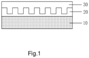
- Figure 1 shows a schematic atomic structure of the silicon-based lithium storage material according to an embodiment of the present disclosure.
- An embodiment of the present disclosure provides a silicon-based lithium storage material, according to the independent claim 1.
- Si with a valence of 0-4 includes a Si particle in an elemental state, a silicon oxide SiO x (0 ⁇ x ⁇ 2) and a silicate such as a compound represented by a general formula M y SiO 3 , where 1 ⁇ y ⁇ 2, and M is an element of groups IA, IIA and IIIA, such as Li, Na, Mg, Ca, or Al, etc.
- C Si(1-4) /C Si(0) 0 ⁇ C Si(1-4) /C Si(0) ⁇ 1
- C Si(1-4) refers to the molar amount of silicon with a valence of 1-4
- C Si(0) refers to the molar amount of silicon atom present in a form of elementary substance and with a valence of 0
- C Si(1-4)/ C Si(0) refers to a molar ratio (a ratio of the number of an atom) of a silicon with a valence of 1-4 to elementary substance silicon.
- the value of C Si(1-4) /C Si(0) can be achieved by adjusting the contents of the silicon particle, the silicon oxide, and the silicate contained in the silicon-based lithium storage material.
- the doping element is marked as R, then the doping element R may be an element that is capable of accepting electrons, and at least include one of elements of group IA, group IIA, and group IIIA.
- the elements of group IA, group IIA, and group IIIA are Li, Na, Mg, Ca, Al and so on.
- the elements of group IA, group IIA, and group IIIA can be combined with other elements capable of accepting electrons to form an electrically neutral material.
- the other elements capable of accepting electrons include N, P, O, C, S, Se, and so on.
- the doping element R may be present in an atomic state or an ionic state in the silicon-based lithium storage material, and atoms of the doping element may combine with each other to form an ionic state, such as elementary substance Mg or elementary substance Al; for another example, the elements of group IA, group IIA, and group IIIA combine with one or more of N, P, O, C, S, Se to form a metal oxide or metal salt, such as MgO, Na 2 O, CaO, Na 3 PO 4 , MgSO 3 , etc.
- the doping element may combine with Si with a valence of 0-4 to form a silicon oxide, a silicate, etc., such as MgSiO 3 , CaSiO 3 , Li 2 SiO 3 or Na 2 SiO 3 , etc. Also, 0 ⁇ C R /C Si(0-4) ⁇ 1.5, where C R refers to the molar amount of the doping element R, and C Si(0-4) refers to the molar amount of silicon with a valence of 0-4.
- the doping amount of the doping element R By adjusting the doping amount of the doping element R, it is possible to change the characteristics of the silicon-based lithium storage material under a high-temperature storage condition after being intercalated with an active lithium and obtain the best results, and meanwhile improve the overall cycle performance and first-cycle coulombic efficiency of a battery containing the silicon-based lithium storage material.
- the value of C R /C Si(0-4) is, for example, 0.2, 0.5, 0.8, 1, or 1.2 etc.
- Si with a valence of 0-4 and the doping element R are uniformly distributed.
- the heating treatment could be performed in advance under the protection of inert gas.
- the elemental silicon crystal grains with a valence of 0 in the core the elemental silicon crystal grains and the surrounding compound crystals are in a homogeneous system. All grains has a size not larger than 300 nm, as measured by powder X-ray diffraction and Scherrer calculation and analysis.
- the core As analyzed by differential thermal scanning calorimetry (DSC), the core has 1-2 crystallization transition peaks between 800 and 1000 degrees, and the corresponding activation energy for crystallization transition is 100-250 KJ/mol.
- the 2P result of Si XPS test contains a peak between 98 eV (Si (0) peak) and 102.5 eV (Si(4+) peak)
- the surface of the core of the silicon-based lithium storage material is further coated with a first shell, wherein the first shell is a carbon-containing material has a Raman Id/Ig ratio less than 0.5 and a conductivity lager than 10 2 S/m.
- the first shell layer has a comb-shaped surface, and the comb-shaped structure could improve the cycle performance of a battery made from the silicon-based lithium storage material, and endow the battery with better rate capability.
- the graphitized carbon coating has a thickness of 1-40 nm; for example, the graphitized carbon coating has a thickness of 5 nm, 10 nm, 15 nm, 20 nm, 25 nm, 30 nm, etc.
- the graphitized carbon coating could further improve conduction characteristics of the material.
- the “coated (or coating)” described in the embodiments of the present disclosure may be “partially coated” or “completely coated”.
- the degree of coating in “coated (or coating)” also varies with the manufacturing process of the silicon-based lithium storage material. In some embodiments of the present disclosure, it could be considered as “completely coating” if the graphitized carbon coating has a thickness of around 5 nm.
- the graphitized carbon coating has a crystalline carbon structure with a high graphitization, it has a certain binding effect on the expansion of the silicon-based lithium storage material when being intercalated with lithium, and could prevent the cracking of the coating and the deactivation of the active substance material in the silicon-based lithium storage material during the deintercalation of lithium. Therefore, the first shell makes it possible to better adjust the charge-discharge performance of the silicon-based lithium storage material and improve the cycle life of the battery.
- the graphitized carbon coating is doped with nitrogen atoms.
- the nitrogen atom may be derived from a N-containing substance, such as one or more of NH 3 , tripolycyanamide, acetonitrile, aniline or butylamine. Introducing nitrogen atoms to the graphitized carbon coating could further improve the charge-discharge capability of the silicon-based lithium storage material, because nitrogen doping can further improve conductivity of the material, so as to reduce internal resistance of the battery, thereby ensuring charge and discharge capacity of the battery with a large current.
- the silicon-based lithium storage material further comprises a second shell coating the first shell, wherein the second shell is a metal oxide that has a dielectric constant of 10-40.
- the second shell is a coexisting phase formed from one or more selected from the group consisting of a oxide of a group IIA element, a oxide of a rare earth element, and a compound formed between Ti, Zr and oxygen.
- the second shell is one or more selected from the group consisting of MgO, CaO, Al 2 O 3 , TiO 2 , ZrO 2 , CeO 2 , Eu 2 O 3 , and Y 2 O 3 .
- the second shell is a ceramic like material, which is formed on the outer layer of the silicon-based lithium storage material, to prevent lithium leakage from the material and significantly improve the safety performance of the silicon-based lithium storage material after being made into a battery.
- the silicon-based lithium storage material is a homogeneous doped system, so as to realize a uniform modification of the valence state, structure, crystal shape, and magnetic environment of the silicon-based lithium storage material, improve its characteristics under a high-temperature storage condition after it is intercalated with an active lithium as an active substance of a lithium-ion secondary battery and obtain the best result, and meanwhile improve cycle characteristics and initial charge-discharge coulombic efficiency of the battery.
- the cycle performance, stability and safety characteristics of the silicon-based lithium storage material as a whole is improved, and meanwhile meets market requirements for higher capacity, higher first-cycle coulombic efficiency and higher safety of lithium-ion batteries.
- the present disclosure also provides a method for preparing a silicon-based lithium storage material, according to the independent claim 7, comprising
- the elementary substance silicon is, for example, polysilicon.
- the silicon with an oxidation state of +4 is, for example, silica, and the raw material containing silica is, for example, quartz, and optionally, for example, ⁇ -type quartz.
- the silicon with an oxidation state of +4 may also be a silicate, for example, a compound represented by a general formula M y SiO 3 , where 1 ⁇ y ⁇ 2, and M is an element of group IA, group IIA, and group IIIA such as Li, Na, Mg, Ca, etc .
- the first mixture comprises a doping element R, where the doping element Rat least includes one of N, P, O, C, S, and Se, and may also includes elements of group IA, group IIA, and group IIIA such as Li, Na, Mg, Ca, etc.; the raw material providing the doping element may be an metal elementary substance such as Mg, or may be a metal oxide, a metal hydroxide, or a metal salt, such as MgO, Na 2 O, CaO, Na 3 PO 4 , MgSO 3 , LiOH, Li 2 CO 3 , MgCO 3 , MgSiO 3 , CaSiO 3 , Li 2 SiO 3 or Na 2 SiO 3 , etc.
- the doping element Rat least includes one of N, P, O, C, S, and Se and may also includes elements of group IA, group IIA, and group IIIA such as Li, Na, Mg, Ca, etc.
- the raw material providing the doping element may be an metal elementary substance such as Mg, or may be
- a composition ratio of each raw material in the first mixture is adjusted, to meet the proviso that 0 ⁇ C R /C Si(0-4) ⁇ 1.5, where C R is the molar amount of the doping element R, and C Si(0-4) is the molar amount of element silicon with a valance of 0-4, for example, the sum of the molar amount of the silicon atoms in elementary substance silicon and silicon with an oxidation state of +4.
- the raw material includes polysilicon, ⁇ -type quartz and Li 2 CO 3 .
- the raw material includes polysilicon, ⁇ -type quartz and LiOH.
- the raw material includes polysilicon, ⁇ -type quartz, and MgCO 3 .
- the non-oxidizing gas described in the embodiments of the present disclosure is, for example, an inert gas, such as helium, neon, and argon etc.
- the temperature when heating to a molten state is for example, 2000 °C, 2500 °C, etc.
- the molten mixture is cooled rapidly to room temperature at a cooling rate of 5 °C/S-30 °C/S (°C/S: Celsius/second).
- the rapid cooling process may make the prepared material have the best cycle performance after being made into a battery.
- cooling the molten first mixture to room temperature at a cooling rate of 5 °C/S-30 °C/S comprises pouring the molten first mixture onto a rapidly rotating roller, and separating the molten first mixture from the roller by a centrifugal action of the roller, to obtain a flaky cooled product.
- the rapidly rotating may be adjusted according to the gear position or the rotation speed setting of the used equipment with rollers, and is not specifically limited in the present disclosure.
- the atoms in the silicon-based lithium storage material are recombined, to meet the proviso that 0 ⁇ C Si(1-4) /C Si(0) ⁇ 1, where C Si(1-4) is the molar amount of element silicon with a valence of 1-4, and C Si(0) is the molar amount of element silicon with a valence of 0.
- a process for pulverizing the flaky cooled product may be any conventional process for pulverizing and performed with any conventional device, which will not repeated here.
- the pulverized silicon-based lithium storage material has a median particle size of 1-8 ⁇ m.
- Step S2 is performed.
- a surface of the core is coated with a first shell, wherein the first shell is a carbon-containing material that has a Raman Id/Ig ratio less than 0.5 and a conductivity lager than 10 2 S/m.
- a process for coating a surface of the core with a first shell is a deposition-coating process.
- the first shell for example is a carbon coating.
- a process for depositing the carbon coating comprises
- a coating equipment such as a revolver, a rotary furnace and the like can be used to prepare the carbon coating, to achieve a uniform coating.
- the coating equipment may be configured to comprise a pre-decomposition zone and a depositing-coating zone, wherein both the pre-decomposition zone and the depositing-coating zone comprise a reaction chamber.
- the pre-decomposition zone is used to pre-decompose the carbon source substance.
- the carbon source substance is introduced into the pre-decomposition zone of the coating equipment, and then subjected to pyrolysis, cracking, polycondensation reactions and the like in a non-oxidizing atmosphere, to become a gaseous substance.
- the carbon source comprises a low-molecular-weight substance and a high-molecular-weight substance, wherein the low-molecular-weight substance becomes a medium/large-molecular-weight substance via pyrolysis, polycondensation, and addition reactions and the like; the high-molecular-weight substance is cracked into a medium/small-molecular-weight substance, which is also accompanied by pyrolysis, polycondensation, addition reactions and the like.
- the gas that provides the non-oxidizing atmosphere includes, for example, any one or more of hydrogen, nitrogen, or inert gas, and is used as a protective gas, a carrier gas, and a diluent gas for the reaction in the pre-decomposition zone.
- the gaseous carbon source substance includes a hydrocarbon that is gaseous at room temperature and an aldehyde that is gaseous at room temperature.
- the gaseous carbon source substance includes methane, ethane, ethylene, acetylene, propane, and propylene.
- the vaporized carbon source substance is the carbonaceous material that is liquid at room temperature, and is gaseous at a temperature above room temperature but lower than the temperature of the pre-decomposition zone.
- the vaporized carbon source substance includes n-hexane, ethanol, and benzene.
- the atomized carbon source substance is a substance that is difficult to evaporate by heating, and can be made into small droplets by an atomizing device, for example, a substance that is liquid at a temperature lower than the temperature of the pre-decomposition zone.
- the atomized carbon source substance includes polyethylene and polypropylene.
- the flow rate V G of the decomposition product into the reaction chamber of the depositing-coating zone and a ratio M C /M of the molar flow rate of the decomposition product to the mass of the core are adjusted, to subject the core and the decomposition product to a depositing and coating reaction in the depositing-coating zone, forming a graphitized carbon coating on a surface of the core, with the proviso that 10 ⁇ V G ⁇ 100 and 0.001 ⁇ M C /M ⁇ 1, where V G is in a unit of m/min, M C is in a unit of mol/min, in terms of carbon atoms, and M is the mass of the core, in a unit of kg.
- the first shell is a graphitized carbon coating. That is to say, in the preparation process of the silicon-based lithium storage material described in the embodiments of the present disclosure, the thickness of the formed graphitized carbon coating may be adjusted by adjusting the flow rate and mass of the reactants and the reaction time.
- the crystal structure of the carbon coating can be controlled by adjusting V G (m/min) and M C /M (M C is in a unit of mol/min, in terms of carbon atoms, and M is the mass of the core, in a unit of kg), thereby obtaining a graphitized carbon coating.
- V G m/min
- M C is in a unit of mol/min, in terms of carbon atoms
- M is the mass of the core, in a unit of kg
- Adjusting the operation speed of the core and the flow rate of the decomposition product into the reaction chamber can ensure that a uniform and continuous graphitized carbon coating are obtained during the reaction process, and meanwhile the loss of materials could be reduced.
- the graphitized carbon coating Since the graphitized carbon coating has a crystalline carbon structure with a high graphitization, it has a certain binding effect on the expansion of the silicon-based lithium storage material when being intercalated with lithium, and prevents the cracking of the coating and the deactivation of the active substance in the silicon-based lithium storage material during the deintercalation of lithium. Therefore, the graphitized carbon coating structure makes it possible to better adjust the charge-discharge performance of the silicon-based lithium storage material and improve the cycle life of the battery.
- a molar flow rate M C of the pyrolysis product after thermally decomposing the atomized carbon source in the pre-decomposition zone can be determined by measuring the CO 2 content after an oxidative combustion.
- a molar flow rate M C of the pyrolysis product can be directly determined according to the molecular structure of the intake gas.
- the temperature range for pre-decomposing the carbon source substance is set to 500-1500 °C, and preferably 700 °C-1300 °C, so that the carbon source substance can turn into gaseous in the pre-decomposition zone, and be quickly subjected to pyrolysis or polycondensation reactions, forming a pre-decomposition zone product that can quickly be subjected to the subsequent coating reaction.
- the desired temperature can be realized by means of a conventional heating method or microwave or a radio frequency method.
- the microwave heating method can ionize the C-containing substance, and reduce the pre-decomposition temperature and improve the pre-decomposition efficiency compared with other heating methods.
- the gaseous carbon source substance after passing through the pre-decomposition zone, is subjected to dehydrogenation, free radical addition reactions and the like, tobecome a straight-chain or aromatic compound with a larger relative molecular mass and a lower Gibbs free energy.
- the vaporized carbon source substance After passing through the pre-decomposition zone, the vaporized carbon source substance is subjected to dehydrogenation (cracking), free radical addition reactions and the like, to become a straight-chain or aromatic compound.
- the atomized carbon source substance After passing through the pre-decomposition zone, is subjected to cracking, free radical addition reactions and the like, to become a straight-chain or aromatic compound.
- the mixed gas that passes through the pre-decomposition zone is a decomposition product
- the decomposition product comprises a non-oxidizing gas that are introduced into the reaction atmosphere and a pre-decomposed carbon source substance.
- the pre-decomposition reaction step can make the reaction temperature control in the preparation method of the silicon-based lithium storage material more flexible, is beneficial to control the reaction progress (such as the decomposition, addition etc.) of the carbon source substance, and has little interference to the temperature in the coating zone.
- the decomposition product is introduced into the depositing and coating zone of the coating equipment, so that the core and the pre-decomposed carbon source substance can be subjected to a depositing and coating reaction, so as to form a graphitized carbon coating on a surface of the core, wherein the surface of the core is directly coated by the graphitized carbon coating.
- the depositing and coating reaction is carried out at a temperature of 500 °C-1100 °C.
- the depositing and coating reaction is carried out at a temperature of 650 °C-1000 °C.
- the temperature is too low, the C/H ratio of the coating on the surface of the anode material is too high, resulting in poor conductivity and having a negative effect on performance; if the temperature is too high, the silicon oxide in the core may be excessively disproportionated, having a negative effect on the capacity and cycle performance of the silicon-based lithium storage material.
- a N-containing substance may also be introduced.
- the N-containing substance includes one or more of NH 3 , acetonitrile, aniline, or butylamine.
- Step S3 coating a surface of the first shell with a second shell, wherein the second shell is a metal oxide that has a dielectric constant of 10-40.
- the second shell is a coexisting phase formed from one or more selected from the group consisting of a oxide of a group IIA element, a oxide of a rare earth element, and a compound formed between Ti, Zr and oxygen.
- the second shell is one or more selected from the group consisting of MgO, CaO, Al 2 O 3 , TiO 2 , ZrO 2 , CeO 2 , Eu 2 O 3 , and Y 2 O 3 .
- the second shell is a ceramic like material, which is formed on the outer layer of the silicon-based lithium storage material, to prevent lithium leakage of the material and significantly improve the safety performance of the silicon-based lithium storage material after being made into a battery.
- a precursor compound or a combination thereof is selected and mixed with the core coated with the first shell, and the precursor compound (which could be decomposed into the second shell) is decomposed through a thermal decomposition reaction. Thereby, a surface of the first shell is coated with a second shell.
- the precursor compound could be directly mixed with the core coated with the first shell, and then heated to a decomposition temperature of the precursor compound, thereby coating a surface of the first shell with a second shell.
- the precursor compound may also be gasified, and the gasified precursor compound and the core coated with the first shell are introduced into a reaction chamber where the depositing and coating reaction occurs.
- the temperature in the reaction chamber is set greater than or equal to the decomposition temperature of the precursor compound and maintained for a specific time, thereby coating a surface of the first shell with a second shell.
- Ti(OC 2 H 5 ) 4 is selected as the precursor compound. After Ti(OC 2 H 5 ) 4 was heated to a temperature higher than the boiling point of Ti(OC 2 H 5 ) 4 , it is introduced into a reaction chamber of a vapor deposition equipment at a certain flow rate.
- the core coated with the first shell is also sent into the reaction chamber of the vapor deposition equipment. Steam condensation deposition occurs in the reaction chamber, so that the precursor compound is decomposed, a surface of the first shell is coated with TiO 2 after decomposition.
- TiO 2 has a thickness of greater than 0 nm and less than 20 nm, for example, the second shell has a thickness of 5 nm, 10 nm, 13 nm, 18 nm, etc.
- a physical vapor deposition process could be adopted directly to directly deposit the second shell on the surface of the first shell.
- a second shell material such as one or more of MgO, CaO, Al 2 O 3 , TiO 2 , ZrO 2 , CeO 2 , Eu 2 O 3 and Y 2 O 3 , and the core coated with the first shell are placed in a physical vapor deposition equipment and heated until the second shell material evaporates and deposits on the surface of the first shell.
- the first mixture was prepared, and it comprised a component A (polysilicon), a component B ( ⁇ -type quartz), and a component C (Li 2 CO 3 ), wherein the doping element R was based on element Li in the component C.
- the molar ratio of the component B to the component A (marked as Si(+4)/Si(0), representing a molar ratio of silicon with a valance of +4 in the component B to silicon with a valance of 0 in the component A) was 5: 3, and the molar ratio of element Li in the component C to element Si in the component A and the component B (C R /C Si(0-4) ) was 0.5.
- the first mixture was heated to 2600 °C and into a molten state under the protection of argon gas and then cooled to room temperature at a cooling rate of 20 °C/S (the molten first mixture was poured onto a fast roller and separated from the roller by a centrifugal action of the roller, to obtain a flaky cooled product).
- the flaky cooled product was then subjected to a pulverization to form a powder with a median particle size of 5 ⁇ m, as the core of the silicon-based lithium storage material.
- a rotary furnace including a pre-decomposition zone and a depositing-coating zone was used.
- 1 kg of the core (with a median particle size of 5 ⁇ m) of the silicon-based lithium storage material of silicon is used as the silicon substrate material, nitrogen was used as the protective gas.
- a mixture of ethane gas and ethanol vapor with a flow rate V G of 10 m/min was introduced into the pre-decomposition area, in which the molar ratio of ethane to ethanol was 1 : 1, and the reaction temperature was 900 °C.
- M C /M was adjusted to 0.05 mol/min, and the pre-decomposed product was introduced into the depositing-coating zone of the rotary furnace, in which the temperature was 900 °C, and the total reaction time was 20 min, forming a first shell on the surface of the core, with a thickness of 10 nm.
- the core material coated with the first shell was introduced into a chemical vapor deposition equipment, and magnesium isopropoxide was heated to vaporize, and then introduced into the chemical vapor deposition equipment. Magnesium isopropoxide was decomposed by rapid condensation, and thereby a second shell of MgO was coated on the surface of the first shell, and the thickness of the second shell was 5 nm.
- a first mixture was prepared.
- the first mixture comprised component A (polysilicon), component B ( ⁇ -Type quartz), and component C (MgCO 3 ).
- the doped element R was based on Mg element in component C.
- a molar ratio of component B to component A (marked as Si(+4) / Si(0), representing the molar ratio of +4-valent silicon in component B to 0-valent silicon in component A was 5 : 5, and the molar ratio of Mg element in component C to Si element in component A and component B (C R /C Si(0-4) ) was 0.9.
- the first mixture was heated to 2600 °C to a molten state under the protection of argon, and then cooled to room temperature at a cooling rate of 15 °C/S (the molten first mixture was poured onto a fast roller, and separated from the roller through the centrifugal action of the roller, obtaining a flaky cooled product).
- the flaky cooled product was pulverized, forming a powder with a median particle size of 4 ⁇ m, as the core of the silicon-based lithium storage material.
- a rotary furnace including a pre-decomposition zone and a depositing-coating zone was used.
- 1 kg of the core (with a median particle size of 4 ⁇ m) of the silicon-based lithium storage material of silicon was used as the silicon substrate material.
- Nitrogen was used as the protective gas.
- a mixture of ethane gas and ethanol vapor with a flow rate V G of 30 m/min was introduced into the pre-decomposition zone, in which the molar ratio of ethane to ethanol was 1 : 1.
- the reaction temperature was 950 °C.
- M C /M was adjusted to 0.03 mol/min, and the pre-decomposed product mixture was introduced into the depositing-coating zone of the rotary furnace.
- the temperature in the depositing-coating zone was 1000 °C.
- the total reaction time was 20 min, and thereby a first shell was formed on the surface of the core, with a thickness of 12 nm.
- the core material coated with the first shell was introduced into a chemical vapor deposition equipment, and magnesium isopropoxide was heated to vaporize and then also introduced into the chemical vapor deposition equipment. Magnesium isopropoxide was decomposed by rapid condensation, and a second shell of MgO was coated on the surface of the first shell, and the thickness of the second shell was 20 nm.
- a first mixture was prepared.
- the first mixture comprised component A (polysilicon) and component B ( ⁇ -Type quartz), and component C (LiOH).
- the doped element R was based on Li element in component C.
- the molar ratio of component B to component A (marked as Si (+4)/Si(0), representing the molar ratio of +4-valent silicon in component B to 0-valent silicon in component A) was 5 : 3, and the molar ratio of Li element in component C to Si element in component A and component B (C R /C Si(0-4) ) was 1.2.
- the first mixture was heated to 2800 °C to a molten state under the protection of argon, and then cooled to room temperature at a cooling rate of 10 °C/S (the molten first mixture was poured onto a fast roller, and separated from the roller through the centrifugal action of the roller, obtaining a flaky cooled product).
- the flaky cooled product was pulverized, forming a powder with a median particle size of 8 ⁇ m, as the core of the silicon-based lithium storage material.
- a rotary furnace including a pre-decomposition zone and a depositing-coating zone was used.
- 1 kg of the core (with a median particle size of 8 ⁇ m) of the silicon-based lithium storage material of silicon was used as the silicon substrate material.
- Nitrogen was used as the protective gas.
- a mixture of ethane gas and ethanol vapor with a flow rate V G of 60 m/min was introduced into the pre-decomposition zone, in which the molar ratio of ethane to ethanol was 1 : 1.
- the reaction temperature was 1000 °C.
- M C /M was adjusted to 0.08 mol/min, and the pre-decomposed product mixture was introduced into the depositing-coating zone of the rotary furnace.
- the temperature in the depositing-coating zone was 1050 °C.
- the total reaction time was 20 min, and thereby a first shell was formed on the surface of the core, with a thickness of 8 nm.
- the core material coated with the first shell was introduced into a chemical vapor deposition equipment, and phenylmagnesium bromide was heated to vaporize and also introduced into the chemical vapor deposition equipment. Phenylmagnesium bromide was decomposed by rapid condensation. A second shell of MgO was coated on the surface of the first shell, and the thickness of the second shell was 8 nm.
- Examples 4-10 were performed according to the Examples except that the process parameters were adjusted, forming the silicon-based lithium storage materials shown in Examples 1 to 10 as described in Table 1.
- the silicon-based lithium storage material could pass through the acupuncture test, indicating that the second shell formed on the outer layer of the silicon-based lithium storage material could prevent lithium leakage from the material and significantly improve the safety performance of the silicon-based lithium storage material after being made into a battery.
- the acupuncture experiment was performed according to the acupuncture method specified in GBT 31485-2015.
- the prepared silicon-based lithium storage material was mixed with standard graphite material (with a capacity of 355 mAh/g and a first-cycle coulombic efficiency of 93%) to form 420 mAh/g negative electrode material, and then a soft pack battery made from the same was tested .
- the silicon-based lithium storage material formed by the method for preparing the silicon-based lithium storage material as described in this example was used as the negative electrode material of a lithium battery, the first-cycle lithium removal capacity, first-cycle coulombic efficiency and 100-cycle capacity retention at room temperature were much higher than those of the silicon-based negative electrode material in comparative example.
- the cycle performance, stability and safety characteristics of the silicon-based lithium storage material as a whole were improved, and meanwhile the requirements for high-capacity, high first-cycle coulombic efficiency and high safety of lithium-ion batteries were met, meeting the market demand.
- the silicon-based lithium storage material was a doped homogeneous system, which realized the uniform modification of the valence state, structure, crystal form and magnetic environment of the silicon-based lithium storage material, improved its characteristics under a high-temperature storage condition after it is intercalated with an active lithium as an active substance of a lithium-ion secondary battery and obtain the best result, and improved the cycle characteristics and initial charge-discharge coulombic efficiency of the battery.
- first, second, third, etc. may be used herein to describe various elements, these elements should not be limited by these terms. These terms are only used to distinguish one element from another. Therefore, the first element in some embodiments may be referred to as the second element in other embodiments without departing from the teachings of the present disclosure.
- the same reference numerals or the same reference signs denote the same elements throughout the specification.
Landscapes
- Chemical & Material Sciences (AREA)
- Chemical Kinetics & Catalysis (AREA)
- Electrochemistry (AREA)
- General Chemical & Material Sciences (AREA)
- Composite Materials (AREA)
- Engineering & Computer Science (AREA)
- Materials Engineering (AREA)
- Manufacturing & Machinery (AREA)
- Inorganic Chemistry (AREA)
- Battery Electrode And Active Subsutance (AREA)
- Silicon Compounds (AREA)
Description
- The present disclosure relates to the field of lithium ion batteries, and in particular to a silicon-based lithium storage material and a preparation method thereof.
- In recent years, higher requirements for the energy performance of lithium-ion batteries have been put forward, resulting in the need of anode materials with a higher capacity, higher first-cycle coulombic efficiency, and higher safety. At present, silicon-oxygen anodes began to be used in power batteries, with a rapidly growing trend. Existing technologies for preparing anode materials of lithium battery starting from silicon oxide are mostly those that use raw materials containing silicon particles (Si) and silicon oxide (SiO2) to obtain the anode materials of lithium battery under high-temperature and vacuum conditions. The silicon-based lithium storage materials prepared by the method have a low first-time coulombic efficiency and a poor cycle characteristics, and it is difficult for the method to form a silicon-based lithium storage material containing uniformly doped elements (such as sulfur, phosphorus, etc.).
- D1 (
WO2019103499A1 ) discloses an anode active material for a lithium secondary battery, capable of exhibiting excellent initial efficiency and lifespan characteristics since the anode active material comprises silicon-based particles represented by M-SiOx (M is Li, Mg, Ca, Al or Ti, and 0≤x<2), wherein the M-SiOx comprises 20-70 wt% of an amorphous phase; and a preparation method therefor. - D2 (
US2005233213A1 ) discloses a negative active material for a rechargeable lithium battery, which includes a silicon-based composite having a silicon oxide of the form SiOx where x<=1.5 and at least one element selected from the group consisting of B, P, Li, Ge, Al, and V, and a carbonaceous material. - D3 (
EP3518328A1 ) discloses a silicon composite including a porous silicon secondary particle and a first carbon flake on a surface of the porous silicon secondary particle; a carbonaceous coating layer on the porous silicon composite, the carbonaceous coating layer comprising a first amorphous carbon; and the silicon composite comprises a second amorphous carbon and has a density that is equal to or less than a density of the carbonaceous coating layer, wherein the porous silicon secondary particle includes an aggregate of silicon composite primary particles, each including silicon, a silicon suboxide on a surface of the silicon, and a second carbon flake on a surface of the silicon suboxide. - D4 (
CN107195890B ) discloses a high-performance lithium ion battery negative electrode Si@N-C composite material and a preparation method therefor. In the method, gulfweed is used as the raw material to prepare SiO2 and then reduction is preformed to obtain a Si material; and next, pyrrole is used as the main raw material to coat polypyrrole on the surface of the Si material, and calcining is preformed to obtain the Si@N-C composite material. - D14 (
CN109713286A ) discloses a silicon-based composite material used for a lithium ion secondary battery and a preparation method thereof. The composite material includes a silicon-based material particle having lithium ions, the silicon-based material particle has a core-shell structure, and the outside of the particle is coated with a composite film layer; the composite film layer is divided into two layers: the inner layer is a carbon film layer completely covering or partially covering the surface of the silicon-based material particle or a carbon film/conductive additive composite film layer formed by the carbon film layer and a conductive additive; the outer layer is a partially crystallized or completely crystallized metal compound cladding layer, and the cladding layer completely covers or partially covers the surface of the silicon-based material particle or the surface of the inner layer. - D15 (
CN101986442A ) discloses a lithium ion battery cathode material containing a three-dimensional conductive structure and a preparation method thereof. Nano silicon powder is adopted as a core and is coated by a nano carbon material to form a core-containing conductor, and the core-containing conductor is coated by nano metal or metal oxide again, so lithium ion battery cathode material silicon nanoparticles containing the three-dimensional conductive structure are formed through the two-time coating. - Therefore, it is necessary to provide a new silicon-based lithium storage material and a preparation method thereof.
- The present disclosure provides a new silicon-based lithium storage material and a preparation method thereof, to obtain a silicon-based lithium storage material with market-required higher capacity, higher first-cycle coulombic efficiency, and higher safety.
- One aspect of the present disclosure provides a silicon-based lithium storage material, according to the independent claim 1, comprising
- a core comprising
- a first component, comprising Si with a valence of 0-4, with the proviso that 0≤CSi(1-4)/CSi(0)≤1, where CSi(1-4) is a molar amount of element silicon with a valence of 1-4, and CSi(0) is a molar amount of element silicon with a valence of 0; and
- a second component, comprising a doping element R, where the doping element R is an element that accepts electrons, and
- with the proviso that 0≤CR/CSi(0-4)≤1.5, where CR is a molar amount of the doping element R, and CSi(0-4) is a molar amount of element silicon with a valence of 0-4;
- a first shell coating the core, wherein the first shell is a carbon-containing material that has a conductivity lager than 102 S/m; and
- a second shell coating the first shell, wherein the second shell is a metal oxide that has a dielectric constant of 10-40, said metal oxide is selected from MgO, Al2O3 and TiO2,
- characterized in that,
- the first shell is a graphitized carbon coating;
- the second shell has a thickness of 5-20 nm; and
- Si with a valence of 0-4 and the doping element R are uniformly distributed.
- In some embodiments of the present disclosure, the graphitized carbon coating is doped with nitrogen atoms.
- In some embodiments of the present disclosure, the second shell is a coexisting phase formed from one or more selected from the group consisting of a oxide of a group IIA element, a oxide of a rare earth element, and a compound formed between Ti, Zr and oxygen.
- In some embodiments of the present disclosure, the doping element R at least comprises one of elements of group IA, group IIA, and group IIIA.
- In some embodiments of the present disclosure, the elements of group IA, group IIA, and group IIIA comprises Li, Na, Mg, Ca, or Al.
- In some embodiments of the present disclosure, the first shell has a thickness of 1-40 nm.
- The present disclosure also provides a method for preparing a silicon-based lithium storage material, according to the independent claim 7, comprising
- preparing a core of the silicon-based lithium storage material, wherein the core comprises
- a first component, comprising Si with a valence of 0-4, with the proviso that 0≤CSi(1-4)/CSi(0)≤1, where CSi(1-4) is a molar amount of element silicon with a valence of 1-4, and CSi(0) is a molar amount of element silicon with a valence of 0; and
- a second component, comprising a doping element R, where the doping element R is an element that is capable of accepting electrons, with the proviso that 0≤CR/CSi(0-4)≤1.5, where CR is a molar amount of the doping element R, and CSi(0-4) is a molar amount of element silicon with a valence of 0-4;
- coating a surface of the core with a first shell, wherein the first shell is a carbon-containing material that has a conductivity lager than 102 S/m, the first shell being a graphitized carbon coating; and
- coating a surface of the first shell with a second shell, wherein the second shell is a metal oxide that has a dielectric constant of 10-40, said metal oxide is selected from MgO, Al2O3 and TiO2,
- characterized in that, preparing the core of the silicon-based lithium storage material comprises
- providing a first mixture, where the first mixture at least comprises an elementary substance silicon and a silicon with an oxidation state of +4, and also a doping element R, where the doping element R at least comprises one of elements of group IA, group IIA, and group IIIA, with the proviso that 0≤CR/CSi(0-4)≤1.5, where CR is the molar amount of the doping element R, and CSi(0-4) is the molar amount of element silicon with a valence of 0-4;
- heating the first mixture to a molten state under the protection of a non-oxidizing gas, and then cooling to room temperature at a cooling rate of 5 °C/S-30 °C/S, to obtain a flaky cooled product; and
- pulverizing the flaky cooled product to form the core of the silicon-based lithium storage material; wherein
- the temperature when heating to a molten state is 1500 °C-3000 °C;
and
- coating the surface of the first shell with the second shell comprises
mixing a precursor compound or a combination thereof with the core coated with the first shell, and decomposing the precursor compound through a thermal decomposition reaction, and coating a surface of the first shell with a second shell, during which the precursor compound is decomposed into the second shell, wherein - the precursor compound is tetrabutyl titanate, aluminum isopropoxide, magnesium isopropoxide or phenylmagnesium bromide.
- In some embodiments of the present disclosure, cooling the molten first mixture to room temperature at a cooling rate of 5-30 °C/S comprises pouring the molten first mixture onto a fast roller, and separating the molten first mixture from the roller by a centrifugal action of the roller to obtain a flaky cooled product.
- In some embodiments of the present disclosure, coating a surface the core with a first shell comprises
- in a non-oxidizing atmosphere, passing a carbon source substance through a pre-decomposition zone to form a decomposition product, wherein the carbon source substance comprises one or more of a gaseous carbon source substance, a vaporized carbon source substance, and an atomized carbon source substance; and
- adjusting the flow rate VG of the decomposition product into a reaction chamber of a depositing-coating zone, and a ratio Mc/M of the molar flow rate of the decomposition product to the mass of the core, to subject the core and the decomposition product to a depositing and coating reaction in the depositing-coating zone, forming a first shell on the surface of the core, with the proviso that 10≤VG≤100 and 0.001<Mc/M<1, where VG is in a unit of m/min, Mc is in a unit of mol/min, in terms of carbon atoms, and M is the mass of the core, in a unit of kg.
- In some embodiments of the present disclosure, the gaseous carbon source substance includes methane, ethane, ethylene, acetylene, propane, and propylene; the vaporized carbon source substance includes n-hexane, ethanol, and benzene; and the atomized carbon source substance includes polyethylene and polypropylene.
- In some embodiments of the present disclosure, the method further comprises introducing a N-containing substance during the depositing and coating reaction, wherein the N-containing substance includes one or more of NH3, tripolycyanamide, acetonitrile, aniline, and butylamine.
- In some embodiments of the disclosure, through the designs of the first shell and the second shell, the cycle performance, stability and safety characteristics of the silicon-based lithium storage material as a whole are improved, and meanwhile meets market requirements for higher capacity, higher first-cycle coulombic efficiency and higher safety of lithium-ion batteries.
- Additional features in the present disclosure will be described partly below. With the description, the contents described in the following embodiments and accompanying figure will be obvious to those skilled in the art. The inventive conception of the present disclosure can be fully explained by practicing or using the methods, means, and combinations thereof set forth in the detailed examples discussed below.
- The following figure describes in detail the exemplary embodiments disclosed in this disclosure. The same reference numerals indicate similar structures in several views of the figures. Those of ordinary skill in the art would understand that these embodiments are non-limiting and exemplary embodiments. The figure is only for illustration and description purposes, and is not intended to limit the scope of the present disclosure. Embodiments in other ways are also possible to achieve the intention of the disclosure. It should be understood that the figure is not drawn with scale.
-
Figure 1 shows a schematic atomic structure of the silicon-based lithium storage material according to an embodiment of the present disclosure. - The following description provides specific application scenarios and requirements of the present disclosure, with the purpose of enabling those skilled in the art to manufacture and use the content in the present disclosure. For those skilled in the art, various local modifications to the disclosed embodiments are obvious, and the general principles defined herein can be applied to other embodiments and uses without departing from the scope of the present disclosure. Therefore, this disclosure is not limited to the illustrated embodiments, but the scope is consistent with the claims.
- The technical solution of the present disclosure will be described in detail below in conjunction with embodiments and figure.
- An embodiment of the present disclosure provides a silicon-based lithium storage material, according to the independent claim 1.
- In some embodiments of the present disclosure, Si with a valence of 0-4 includes a Si particle in an elemental state, a silicon oxide SiOx (0<x≤2) and a silicate such as a compound represented by a general formula MySiO3, where 1≤y≤2, and M is an element of groups IA, IIA and IIIA, such as Li, Na, Mg, Ca, or Al, etc. Also, 0≤CSi(1-4)/CSi(0)≤1, where CSi(1-4) refers to the molar amount of silicon with a valence of 1-4, CSi(0) refers to the molar amount of silicon atom present in a form of elementary substance and with a valence of 0, and CSi(1-4)/CSi(0) refers to a molar ratio (a ratio of the number of an atom) of a silicon with a valence of 1-4 to elementary substance silicon. The value of CSi(1-4)/CSi(0) can be achieved by adjusting the contents of the silicon particle, the silicon oxide, and the silicate contained in the silicon-based lithium storage material.
- In some embodiments of the present disclosure, the doping element is marked as R, then the doping element R may be an element that is capable of accepting electrons, and at least include one of elements of group IA, group IIA, and group IIIA. The elements of group IA, group IIA, and group IIIA, for example, are Li, Na, Mg, Ca, Al and so on. The elements of group IA, group IIA, and group IIIA can be combined with other elements capable of accepting electrons to form an electrically neutral material. The other elements capable of accepting electrons include N, P, O, C, S, Se, and so on. The doping element R may be present in an atomic state or an ionic state in the silicon-based lithium storage material, and atoms of the doping element may combine with each other to form an ionic state, such as elementary substance Mg or elementary substance Al; for another example, the elements of group IA, group IIA, and group IIIA combine with one or more of N, P, O, C, S, Se to form a metal oxide or metal salt, such as MgO, Na2O, CaO, Na3PO4, MgSO3, etc. The doping element may combine with Si with a valence of 0-4 to form a silicon oxide, a silicate, etc., such as MgSiO3, CaSiO3, Li2SiO3 or Na2SiO3, etc. Also, 0≤CR/CSi(0-4)≤1.5, where CR refers to the molar amount of the doping element R, and CSi(0-4) refers to the molar amount of silicon with a valence of 0-4. By adjusting the doping amount of the doping element R, it is possible to change the characteristics of the silicon-based lithium storage material under a high-temperature storage condition after being intercalated with an active lithium and obtain the best results, and meanwhile improve the overall cycle performance and first-cycle coulombic efficiency of a battery containing the silicon-based lithium storage material. In some embodiments, the value of CR/CSi(0-4) is, for example, 0.2, 0.5, 0.8, 1, or 1.2 etc.
- In the present disclosure, Si with a valence of 0-4 and the doping element R are uniformly distributed. Optionally, in order to obtain a higher first-cycle coulombic efficiency, the heating treatment could be performed in advance under the protection of inert gas. When there are elemental silicon crystal grains with a valence of 0 in the core, the elemental silicon crystal grains and the surrounding compound crystals are in a homogeneous system. All grains has a size not larger than 300 nm, as measured by powder X-ray diffraction and Scherrer calculation and analysis.
- As analyzed by differential thermal scanning calorimetry (DSC), the core has 1-2 crystallization transition peaks between 800 and 1000 degrees, and the corresponding activation energy for crystallization transition is 100-250 KJ/mol. The 2P result of Si XPS test contains a peak between 98 eV (Si (0) peak) and 102.5 eV (Si(4+) peak)
- In some embodiments of the present disclosure, the surface of the core of the silicon-based lithium storage material is further coated with a first shell, wherein the first shell is a carbon-containing material has a Raman Id/Ig ratio less than 0.5 and a conductivity lager than 102 S/m.
- A shown in
Figure 1 , the first shell layer has a comb-shaped surface, and the comb-shaped structure could improve the cycle performance of a battery made from the silicon-based lithium storage material, and endow the battery with better rate capability. - In some embodiments of the present disclosure, the graphitized carbon coating has a thickness of 1-40 nm; for example, the graphitized carbon coating has a thickness of 5 nm, 10 nm, 15 nm, 20 nm, 25 nm, 30 nm, etc.
- In some embodiments of the present disclosure, the graphitized carbon coating could further improve conduction characteristics of the material. The "coated (or coating)" described in the embodiments of the present disclosure may be "partially coated" or "completely coated". The degree of coating in "coated (or coating)" also varies with the manufacturing process of the silicon-based lithium storage material. In some embodiments of the present disclosure, it could be considered as "completely coating" if the graphitized carbon coating has a thickness of around 5 nm.
- Since the graphitized carbon coating has a crystalline carbon structure with a high graphitization, it has a certain binding effect on the expansion of the silicon-based lithium storage material when being intercalated with lithium, and could prevent the cracking of the coating and the deactivation of the active substance material in the silicon-based lithium storage material during the deintercalation of lithium. Therefore, the first shell makes it possible to better adjust the charge-discharge performance of the silicon-based lithium storage material and improve the cycle life of the battery.
- In some embodiments of the present disclosure, the graphitized carbon coating is doped with nitrogen atoms. The nitrogen atom may be derived from a N-containing substance, such as one or more of NH3, tripolycyanamide, acetonitrile, aniline or butylamine. Introducing nitrogen atoms to the graphitized carbon coating could further improve the charge-discharge capability of the silicon-based lithium storage material, because nitrogen doping can further improve conductivity of the material, so as to reduce internal resistance of the battery, thereby ensuring charge and discharge capacity of the battery with a large current.
- In some embodiments of the present disclosure, the silicon-based lithium storage material further comprises a second shell coating the first shell, wherein the second shell is a metal oxide that has a dielectric constant of 10-40. In some embodiments, the second shell is a coexisting phase formed from one or more selected from the group consisting of a oxide of a group IIA element, a oxide of a rare earth element, and a compound formed between Ti, Zr and oxygen. Optionally, the second shell is one or more selected from the group consisting of MgO, CaO, Al2O3, TiO2, ZrO2, CeO2, Eu2O3, and Y2O3. The second shell is a ceramic like material, which is formed on the outer layer of the silicon-based lithium storage material, to prevent lithium leakage from the material and significantly improve the safety performance of the silicon-based lithium storage material after being made into a battery.
- The silicon-based lithium storage material is a homogeneous doped system, so as to realize a uniform modification of the valence state, structure, crystal shape, and magnetic environment of the silicon-based lithium storage material, improve its characteristics under a high-temperature storage condition after it is intercalated with an active lithium as an active substance of a lithium-ion secondary battery and obtain the best result, and meanwhile improve cycle characteristics and initial charge-discharge coulombic efficiency of the battery. Through the designs of the first shell and the second shell, the cycle performance, stability and safety characteristics of the silicon-based lithium storage material as a whole is improved, and meanwhile meets market requirements for higher capacity, higher first-cycle coulombic efficiency and higher safety of lithium-ion batteries.
- The present disclosure also provides a method for preparing a silicon-based lithium storage material, according to the independent claim 7, comprising
- Step S1: preparing a core of the silicon-based lithium storage material, wherein the core comprises
- a first component, comprising Si with a valence of 0-4, with the proviso that 0≤CSi(1-4)/CSi(0)≤1, where CSi(1-4) is a molar amount of element silicon with a valence of 1-4, and CSi(0) is a molar amount of element silicon with a valence of 0; and
- a second component, comprising a doping element R, where the doping element R is an element that is capable of accepting electrons, with the proviso that 0≤CR/CSi(0-4)≤1.5, where CR is a molar amount of the doping element R, and CSi(0-4) is a molar amount of element silicon with a valence of 0-4;
- Step S2: coating a surface of the core with a first shell, wherein the first shell is a carbon-containing material that a conductivity lager than 102 S/m, the first shell being a graphitized carbon coating; and
- Step S3: coating a surface of the first shell with a second shell, wherein the second shell is a metal oxide that has a dielectric constant of 10-40; said metal oxide is selected from MgO, Al2O3 and TiO2,
- characterized in that, preparing the core of the silicon-based lithium storage material comprises
- providing a first mixture, where the first mixture at least comprises an elementary substance silicon and a silicon with an oxidation state of +4, and also a doping element R, where the doping element R at least comprises one of elements of group IA, group IIA, and group IIIA, with the proviso that 0≤CR/CSi(0-4)≤1.5, where CR is the molar amount of the doping element R, and CSi(0-4) is the molar amount of element silicon with a valence of 0-4;
- heating the first mixture to a molten state under the protection of a non-oxidizing gas, and then cooling to room temperature at a cooling rate of 5 °C/S-30 °C/S, to obtain a flaky cooled product; and
- pulverizing the flaky cooled product to form the core of the silicon-based lithium storage material; wherein
- the temperature when heating to a molten state is 1500 °C-3000 °C;
and
- coating the surface of the first shell with the second shell comprises
mixing a precursor compound or a combination thereof with the core coated with the first shell, and decomposing the precursor compound through a thermal decomposition reaction, and coating a surface of the first shell with a second shell, during which the precursor compound is decomposed into the second shell, wherein - the precursor compound is tetrabutyl titanate, aluminum isopropoxide, magnesium isopropoxide or phenylmagnesium bromide.
- In the embodiment of the present disclosure, the elementary substance silicon is, for example, polysilicon. The silicon with an oxidation state of +4 is, for example, silica, and the raw material containing silica is, for example, quartz, and optionally, for example, β-type quartz. The silicon with an oxidation state of +4 may also be a silicate, for example, a compound represented by a general formula MySiO3, where 1≤y≤2, and M is an element of group IA, group IIA, and group IIIA such as Li, Na, Mg, Ca, etc .
- The first mixture comprises a doping element R, where the doping element Rat least includes one of N, P, O, C, S, and Se, and may also includes elements of group IA, group IIA, and group IIIA such as Li, Na, Mg, Ca, etc.; the raw material providing the doping element may be an metal elementary substance such as Mg, or may be a metal oxide, a metal hydroxide, or a metal salt, such as MgO, Na2O, CaO, Na3PO4, MgSO3, LiOH, Li2CO3, MgCO3, MgSiO3, CaSiO3, Li2SiO3 or Na2SiO3, etc.
- A composition ratio of each raw material in the first mixture is adjusted, to meet the proviso that 0≤CR/CSi(0-4)≤1.5, where CR is the molar amount of the doping element R, and CSi(0-4) is the molar amount of element silicon with a valance of 0-4, for example, the sum of the molar amount of the silicon atoms in elementary substance silicon and silicon with an oxidation state of +4. In some embodiments of the present disclosure, the raw material includes polysilicon, β-type quartz and Li2CO3. In other embodiments of the present disclosure, the raw material includes polysilicon, β-type quartz and LiOH. In still other embodiments of the present disclosure, the raw material includes polysilicon, β-type quartz, and MgCO3.
- The non-oxidizing gas described in the embodiments of the present disclosure is, for example, an inert gas, such as helium, neon, and argon etc. In some embodiments of the present disclosure, the temperature when heating to a molten state is for example, 2000 °C, 2500 °C, etc. After heating to the molten state, the molten mixture is cooled rapidly to room temperature at a cooling rate of 5 °C/S-30 °C/S (°C/S: Celsius/second). The rapid cooling process may make the prepared material have the best cycle performance after being made into a battery.
- In some embodiments of the present disclosure, cooling the molten first mixture to room temperature at a cooling rate of 5 °C/S-30 °C/S comprises pouring the molten first mixture onto a rapidly rotating roller, and separating the molten first mixture from the roller by a centrifugal action of the roller, to obtain a flaky cooled product. The rapidly rotating may be adjusted according to the gear position or the rotation speed setting of the used equipment with rollers, and is not specifically limited in the present disclosure.
- After melting and rapidly cooling the first mixture, the atoms in the silicon-based lithium storage material are recombined, to meet the proviso that 0≤CSi(1-4) /CSi(0)≤1, where CSi(1-4) is the molar amount of element silicon with a valence of 1-4, and CSi(0) is the molar amount of element silicon with a valence of 0.
- A process for pulverizing the flaky cooled product may be any conventional process for pulverizing and performed with any conventional device, which will not repeated here. In some embodiments, the pulverized silicon-based lithium storage material has a median particle size of 1-8 µm.
- After performing Step S1, Step S2 is performed. A surface of the core is coated with a first shell, wherein the first shell is a carbon-containing material that has a Raman Id/Ig ratio less than 0.5 and a conductivity lager than 102 S/m. In some embodiments, for example, a process for coating a surface of the core with a first shell is a deposition-coating process. The first shell for example is a carbon coating. In some embodiments, a process for depositing the carbon coating comprises
- in a non-oxidizing atmosphere, passing a carbon source substance through a pre-decomposition zone to form a decomposition product, wherein the carbon source substance includes at least one of a gaseous carbon source substance, a vaporized carbon source substance, or an atomized carbon source substance;
- adjusting the flow rate VG of the decomposition products into a reaction chamber of a depositing-coating zone, and a ratio Mc/M of the molar flow rate of the decomposition product to the mass of the core, to subject the core and the decomposition product to a depositing and coating reaction in the depositing-coating zone, forming a first shell on a surface of the core, with the proviso that 10≤VG≤100 and 0.001≤MC/M<1, where VG is in a unit of m/min, MC is in a unit of mol/min, in terms of carbon atoms, and M is the mass of the core, in a unit of kg.
- A coating equipment such as a revolver, a rotary furnace and the like can be used to prepare the carbon coating, to achieve a uniform coating. The coating equipment may be configured to comprise a pre-decomposition zone and a depositing-coating zone, wherein both the pre-decomposition zone and the depositing-coating zone comprise a reaction chamber. The pre-decomposition zone is used to pre-decompose the carbon source substance. For example, the carbon source substance is introduced into the pre-decomposition zone of the coating equipment, and then subjected to pyrolysis, cracking, polycondensation reactions and the like in a non-oxidizing atmosphere, to become a gaseous substance. The carbon source comprises a low-molecular-weight substance and a high-molecular-weight substance, wherein the low-molecular-weight substance becomes a medium/large-molecular-weight substance via pyrolysis, polycondensation, and addition reactions and the like; the high-molecular-weight substance is cracked into a medium/small-molecular-weight substance, which is also accompanied by pyrolysis, polycondensation, addition reactions and the like.
- The gas that provides the non-oxidizing atmosphere includes, for example, any one or more of hydrogen, nitrogen, or inert gas, and is used as a protective gas, a carrier gas, and a diluent gas for the reaction in the pre-decomposition zone.
- The gaseous carbon source substance includes a hydrocarbon that is gaseous at room temperature and an aldehyde that is gaseous at room temperature. The gaseous carbon source substance includes methane, ethane, ethylene, acetylene, propane, and propylene. The vaporized carbon source substance is the carbonaceous material that is liquid at room temperature, and is gaseous at a temperature above room temperature but lower than the temperature of the pre-decomposition zone. The vaporized carbon source substance includes n-hexane, ethanol, and benzene.
- The atomized carbon source substance is a substance that is difficult to evaporate by heating, and can be made into small droplets by an atomizing device, for example, a substance that is liquid at a temperature lower than the temperature of the pre-decomposition zone. The atomized carbon source substance includes polyethylene and polypropylene.
- In some embodiments of the present disclosure, the flow rate VG of the decomposition product into the reaction chamber of the depositing-coating zone and a ratio MC/M of the molar flow rate of the decomposition product to the mass of the core are adjusted, to subject the core and the decomposition product to a depositing and coating reaction in the depositing-coating zone, forming a graphitized carbon coating on a surface of the core, with the proviso that 10≤VG≤100 and 0.001≤MC/M<1, where VG is in a unit of m/min, MC is in a unit of mol/min, in terms of carbon atoms, and M is the mass of the core, in a unit of kg. The first shell is a graphitized carbon coating. That is to say, in the preparation process of the silicon-based lithium storage material described in the embodiments of the present disclosure, the thickness of the formed graphitized carbon coating may be adjusted by adjusting the flow rate and mass of the reactants and the reaction time.
- In other words, the crystal structure of the carbon coating can be controlled by adjusting VG (m/min) and MC/M (MC is in a unit of mol/min, in terms of carbon atoms, and M is the mass of the core, in a unit of kg), thereby obtaining a graphitized carbon coating. At the same time, in combination with adjusting the reaction time, the mass percentage content of the carbon coating can be adjusted.
- Adjusting the operation speed of the core and the flow rate of the decomposition product into the reaction chamber can ensure that a uniform and continuous graphitized carbon coating are obtained during the reaction process, and meanwhile the loss of materials could be reduced.
- Since the graphitized carbon coating has a crystalline carbon structure with a high graphitization, it has a certain binding effect on the expansion of the silicon-based lithium storage material when being intercalated with lithium, and prevents the cracking of the coating and the deactivation of the active substance in the silicon-based lithium storage material during the deintercalation of lithium. Therefore, the graphitized carbon coating structure makes it possible to better adjust the charge-discharge performance of the silicon-based lithium storage material and improve the cycle life of the battery.
- In some embodiments of the present disclosure, a molar flow rate MC of the pyrolysis product after thermally decomposing the atomized carbon source in the pre-decomposition zone, can be determined by measuring the CO2 content after an oxidative combustion. For the gaseous and vaporous carbon source, a molar flow rate MC of the pyrolysis product can be directly determined according to the molecular structure of the intake gas.
- In the embodiment of the present disclosure, the temperature range for pre-decomposing the carbon source substance is set to 500-1500 °C, and preferably 700 °C-1300 °C, so that the carbon source substance can turn into gaseous in the pre-decomposition zone, and be quickly subjected to pyrolysis or polycondensation reactions, forming a pre-decomposition zone product that can quickly be subjected to the subsequent coating reaction. In the pre-decomposition zone, the desired temperature can be realized by means of a conventional heating method or microwave or a radio frequency method. However, the microwave heating method can ionize the C-containing substance, and reduce the pre-decomposition temperature and improve the pre-decomposition efficiency compared with other heating methods.
- In some embodiments of the present disclosure, after passing through the pre-decomposition zone, the gaseous carbon source substance is subjected to dehydrogenation, free radical addition reactions and the like, tobecome a straight-chain or aromatic compound with a larger relative molecular mass and a lower Gibbs free energy. After passing through the pre-decomposition zone, the vaporized carbon source substance is subjected to dehydrogenation (cracking), free radical addition reactions and the like, to become a straight-chain or aromatic compound. After passing through the pre-decomposition zone, the atomized carbon source substance is subjected to cracking, free radical addition reactions and the like, to become a straight-chain or aromatic compound.
- In the embodiments of the present disclosure, after the pre-decomposition reaction, the mixed gas that passes through the pre-decomposition zone is a decomposition product, and the decomposition product comprises a non-oxidizing gas that are introduced into the reaction atmosphere and a pre-decomposed carbon source substance. The pre-decomposition reaction step can make the reaction temperature control in the preparation method of the silicon-based lithium storage material more flexible, is beneficial to control the reaction progress (such as the decomposition, addition etc.) of the carbon source substance, and has little interference to the temperature in the coating zone.
- After that, the decomposition product is introduced into the depositing and coating zone of the coating equipment, so that the core and the pre-decomposed carbon source substance can be subjected to a depositing and coating reaction, so as to form a graphitized carbon coating on a surface of the core, wherein the surface of the core is directly coated by the graphitized carbon coating.
- In some embodiments of the present disclosure, the depositing and coating reaction is carried out at a temperature of 500 °C-1100 °C. Preferably, the depositing and coating reaction is carried out at a temperature of 650 °C-1000 °C. During the depositing and coating reaction, if the temperature is too low, the C/H ratio of the coating on the surface of the anode material is too high, resulting in poor conductivity and having a negative effect on performance; if the temperature is too high, the silicon oxide in the core may be excessively disproportionated, having a negative effect on the capacity and cycle performance of the silicon-based lithium storage material.
- During the depositing and coating reaction, a N-containing substance may also be introduced. The N-containing substance includes one or more of NH3, acetonitrile, aniline, or butylamine. By introducing the N-containing substance, it is possible to obtain a graphitized carbon coating doped with N atoms. The graphitized carbon coating doped with N atoms can further improve the charge-discharge capability of the silicon-based lithium storage material, because the graphitized carbon coating after being doped with N can further improve the conductivity of the material, thereby reducing the internal resistance of the battery, and thus ensuring the ability of the battery to charge and discharge with high current.
- After that, refer to Step S3: coating a surface of the first shell with a second shell, wherein the second shell is a metal oxide that has a dielectric constant of 10-40. In some embodiments, the second shell is a coexisting phase formed from one or more selected from the group consisting of a oxide of a group IIA element, a oxide of a rare earth element, and a compound formed between Ti, Zr and oxygen. Optionally, the second shell is one or more selected from the group consisting of MgO, CaO, Al2O3, TiO2, ZrO2, CeO2, Eu2O3, and Y2O3.The second shell is a ceramic like material, which is formed on the outer layer of the silicon-based lithium storage material, to prevent lithium leakage of the material and significantly improve the safety performance of the silicon-based lithium storage material after being made into a battery.
- A precursor compound or a combination thereof is selected and mixed with the core coated with the first shell, and the precursor compound (which could be decomposed into the second shell) is decomposed through a thermal decomposition reaction. Thereby, a surface of the first shell is coated with a second shell.
- In a process for coating a surface of the first shell with a second shell, in some embodiments of the present disclosure, the precursor compound could be directly mixed with the core coated with the first shell, and then heated to a decomposition temperature of the precursor compound, thereby coating a surface of the first shell with a second shell.
- In a process of coating a surface of the first shell with a second shell, in some embodiments of the present disclosure, the precursor compound may also be gasified, and the gasified precursor compound and the core coated with the first shell are introduced into a reaction chamber where the depositing and coating reaction occurs. The temperature in the reaction chamber is set greater than or equal to the decomposition temperature of the precursor compound and maintained for a specific time, thereby coating a surface of the first shell with a second shell. For example, Ti(OC2H5)4 is selected as the precursor compound. After Ti(OC2H5)4 was heated to a temperature higher than the boiling point of Ti(OC2H5)4, it is introduced into a reaction chamber of a vapor deposition equipment at a certain flow rate. The core coated with the first shell is also sent into the reaction chamber of the vapor deposition equipment. Steam condensation deposition occurs in the reaction chamber, so that the precursor compound is decomposed, a surface of the first shell is coated with TiO2 after decomposition. By adjusting the flow rate of the precursor compound and deposition time, TiO2 has a thickness of greater than 0 nm and less than 20 nm, for example, the second shell has a thickness of 5 nm, 10 nm, 13 nm, 18 nm, etc.
- In some embodiments of the present disclosure, as for a process for coating a surface of the first shell with a second shell, a physical vapor deposition process could be adopted directly to directly deposit the second shell on the surface of the first shell. For example, a second shell material such as one or more of MgO, CaO, Al2O3, TiO2, ZrO2, CeO2, Eu2O3 and Y2O3, and the core coated with the first shell are placed in a physical vapor deposition equipment and heated until the second shell material evaporates and deposits on the surface of the first shell.
- The first mixture was prepared, and it comprised a component A (polysilicon), a component B (β-type quartz), and a component C (Li2CO3), wherein the doping element R was based on element Li in the component C. The molar ratio of the component B to the component A (marked as Si(+4)/Si(0), representing a molar ratio of silicon with a valance of +4 in the component B to silicon with a valance of 0 in the component A) was 5: 3, and the molar ratio of element Li in the component C to element Si in the component A and the component B (CR/CSi(0-4)) was 0.5.
- The first mixture was heated to 2600 °C and into a molten state under the protection of argon gas and then cooled to room temperature at a cooling rate of 20 °C/S (the molten first mixture was poured onto a fast roller and separated from the roller by a centrifugal action of the roller, to obtain a flaky cooled product). The flaky cooled product was then subjected to a pulverization to form a powder with a median particle size of 5 µm, as the core of the silicon-based lithium storage material.
- A rotary furnace including a pre-decomposition zone and a depositing-coating zone was used. 1 kg of the core (with a median particle size of 5 µm) of the silicon-based lithium storage material of silicon is used as the silicon substrate material, nitrogen was used as the protective gas. A mixture of ethane gas and ethanol vapor with a flow rate VG of 10 m/min was introduced into the pre-decomposition area, in which the molar ratio of ethane to ethanol was 1 : 1, and the reaction temperature was 900 °C. MC/M was adjusted to 0.05 mol/min, and the pre-decomposed product was introduced into the depositing-coating zone of the rotary furnace, in which the temperature was 900 °C, and the total reaction time was 20 min, forming a first shell on the surface of the core, with a thickness of 10 nm.
- The core material coated with the first shell was introduced into a chemical vapor deposition equipment, and magnesium isopropoxide was heated to vaporize, and then introduced into the chemical vapor deposition equipment. Magnesium isopropoxide was decomposed by rapid condensation, and thereby a second shell of MgO was coated on the surface of the first shell, and the thickness of the second shell was 5 nm.
- A first mixture was prepared. The first mixture comprised component A (polysilicon), component B (β-Type quartz), and component C (MgCO3). The doped element R was based on Mg element in component C. A molar ratio of component B to component A (marked as Si(+4) / Si(0), representing the molar ratio of +4-valent silicon in component B to 0-valent silicon in component A was 5 : 5, and the molar ratio of Mg element in component C to Si element in component A and component B (CR/CSi(0-4)) was 0.9.
- The first mixture was heated to 2600 °C to a molten state under the protection of argon, and then cooled to room temperature at a cooling rate of 15 °C/S (the molten first mixture was poured onto a fast roller, and separated from the roller through the centrifugal action of the roller, obtaining a flaky cooled product). The flaky cooled product was pulverized, forming a powder with a median particle size of 4 µm, as the core of the silicon-based lithium storage material.
- A rotary furnace including a pre-decomposition zone and a depositing-coating zone was used. 1 kg of the core (with a median particle size of 4 µm) of the silicon-based lithium storage material of silicon was used as the silicon substrate material. Nitrogen was used as the protective gas. A mixture of ethane gas and ethanol vapor with a flow rate VG of 30 m/min was introduced into the pre-decomposition zone, in which the molar ratio of ethane to ethanol was 1 : 1. The reaction temperature was 950 °C. MC/M was adjusted to 0.03 mol/min, and the pre-decomposed product mixture was introduced into the depositing-coating zone of the rotary furnace. The temperature in the depositing-coating zone was 1000 °C. The total reaction time was 20 min, and thereby a first shell was formed on the surface of the core, with a thickness of 12 nm.
- The core material coated with the first shell was introduced into a chemical vapor deposition equipment, and magnesium isopropoxide was heated to vaporize and then also introduced into the chemical vapor deposition equipment. Magnesium isopropoxide was decomposed by rapid condensation, and a second shell of MgO was coated on the surface of the first shell, and the thickness of the second shell was 20 nm.
- A first mixture was prepared. The first mixture comprised component A (polysilicon) and component B (β-Type quartz), and component C (LiOH). The doped element R was based on Li element in component C. The molar ratio of component B to component A (marked as Si (+4)/Si(0), representing the molar ratio of +4-valent silicon in component B to 0-valent silicon in component A) was 5 : 3, and the molar ratio of Li element in component C to Si element in component A and component B (CR/CSi(0-4)) was 1.2.
- The first mixture was heated to 2800 °C to a molten state under the protection of argon, and then cooled to room temperature at a cooling rate of 10 °C/S (the molten first mixture was poured onto a fast roller, and separated from the roller through the centrifugal action of the roller, obtaining a flaky cooled product). The flaky cooled product was pulverized, forming a powder with a median particle size of 8 µm, as the core of the silicon-based lithium storage material.
- A rotary furnace including a pre-decomposition zone and a depositing-coating zone was used. 1 kg of the core (with a median particle size of 8 µm) of the silicon-based lithium storage material of silicon was used as the silicon substrate material. Nitrogen was used as the protective gas. A mixture of ethane gas and ethanol vapor with a flow rate VG of 60 m/min was introduced into the pre-decomposition zone, in which the molar ratio of ethane to ethanol was 1 : 1. The reaction temperature was 1000 °C. MC/M was adjusted to 0.08 mol/min, and the pre-decomposed product mixture was introduced into the depositing-coating zone of the rotary furnace. The temperature in the depositing-coating zone was 1050 °C. The total reaction time was 20 min, and thereby a first shell was formed on the surface of the core, with a thickness of 8 nm.
- The core material coated with the first shell was introduced into a chemical vapor deposition equipment, and phenylmagnesium bromide was heated to vaporize and also introduced into the chemical vapor deposition equipment. Phenylmagnesium bromide was decomposed by rapid condensation. A second shell of MgO was coated on the surface of the first shell, and the thickness of the second shell was 8 nm.
- 1 kg of silicon oxide SiOx (x=0.9) with a median particle size of 5 µm were used as the silicon-based material, nitrogen was used as the protective gas, and the reaction temperature was set 900 °C, a graphitized carbon coating with a thickness of 300 nm were deposited on the surface of the silicon-based material, to form a silicon-based anode material. The first-time lithium deintercalation capacity of the material was 760 mAh/g, the first-time coulombic efficiency was 64%, and the a capacity retention after 100 cycles at room temperature was 35%.
- Examples 4-10 were performed according to the Examples except that the process parameters were adjusted, forming the silicon-based lithium storage materials shown in Examples 1 to 10 as described in Table 1.
- It can be seen from the table that when the thickness of the second shell is not 0, the silicon-based lithium storage material could pass through the acupuncture test, indicating that the second shell formed on the outer layer of the silicon-based lithium storage material could prevent lithium leakage from the material and significantly improve the safety performance of the silicon-based lithium storage material after being made into a battery. The acupuncture experiment was performed according to the acupuncture method specified in GBT 31485-2015. The prepared silicon-based lithium storage material was mixed with standard graphite material (with a capacity of 355 mAh/g and a first-cycle coulombic efficiency of 93%) to form 420 mAh/g negative electrode material, and then a soft pack battery made from the same was tested .
- Further, when the silicon-based lithium storage material formed by the method for preparing the silicon-based lithium storage material as described in this example was used as the negative electrode material of a lithium battery, the first-cycle lithium removal capacity, first-cycle coulombic efficiency and 100-cycle capacity retention at room temperature were much higher than those of the silicon-based negative electrode material in comparative example.
Table 1 Performance parameters of the prepared silicon-based lithium storage material in Examples 1-7 Thick ness of the first shell (nm) First shell materi al Precursor material of second shell Thick ness of the secon d shell (nm) Constantcurrent capacity ratio (%, 3C/0.5C) *Acupu ncture test First-c ycle coulo mbic efficie ncy (%) Capacit y retentio n after 300 cycles at room temper at-ure (%) Example 1 10 graphi tized carbon magnesiu m isopropoxi de 5 56 pass through 81 93 Example 2 12 graphi tized carbon magnesiu m isopropoxi de 20 71 pass through 80 80 Example 3 8 graphi tized carbon doped with nitrog en phenylmag nesium bromide 8 50 pass through 83 89 Comparative Example 4 10 graphi tized carbon none 0 56 not pass through 85 90 Comparative Example 5 10 graphi tized carbon doped with nirtrog en none 0 72 not pass through 86 92 Example 6 10 graphi tized carbon tetrabutyl titanate 5 70 pass through 84 91 Example 7 10 graphi tized carbon aluminum isopropoxi de 5 60 pass through 85 95 Example 8 10 graphi tized carbon phenylmag nesium bromide 5 65 pass through 87 93 Example 9 10 graphi tized carbon doped with nitrog en aluminum isopropoxi de 5 75 pass through 86 96 Example 10 10 graphi tized carbon tetrabutyl titanate 10 55 pass through 76 87 - Through the designs of the first shell and the second shell of the silicon-based lithium storage material in examples of the disclosure, the cycle performance, stability and safety characteristics of the silicon-based lithium storage material as a whole were improved, and meanwhile the requirements for high-capacity, high first-cycle coulombic efficiency and high safety of lithium-ion batteries were met, meeting the market demand. Moreover, the silicon-based lithium storage material was a doped homogeneous system, which realized the uniform modification of the valence state, structure, crystal form and magnetic environment of the silicon-based lithium storage material, improved its characteristics under a high-temperature storage condition after it is intercalated with an active lithium as an active substance of a lithium-ion secondary battery and obtain the best result, and improved the cycle characteristics and initial charge-discharge coulombic efficiency of the battery.
- In summary, after reading this detailed disclosure, those skilled in the art may understand that the foregoing detailed disclosure may be presented by way of example only, and may not be limiting. Although not explicitly stated here, those skilled in the art can understand that the present disclosure is intended to include various reasonable changes, improvements, and modifications to the embodiments. These changes, improvements, and modifications are intended to be proposed by the present disclosure, and are within the scope of the exemplary embodiments of the present disclosure.
- It should be understood that the term "and/or" used herein includes any or all combinations of one or more of the associated listed items.
- It should also be understood that the terms "comprising" "comprise(s)", "including", and/or "include(s)", when used herein, indicate the presence of the recited features, wholes, steps, operations, elements and/or components, but it does not exclude the presence or addition of one or more other features, wholes, steps, operations, elements, components, and/or groups thereof.
- It should also be understood that although the terms first, second, third, etc. may be used herein to describe various elements, these elements should not be limited by these terms. These terms are only used to distinguish one element from another. Therefore, the first element in some embodiments may be referred to as the second element in other embodiments without departing from the teachings of the present disclosure. The same reference numerals or the same reference signs denote the same elements throughout the specification.
Claims (11)
- A silicon-based lithium storage material, comprisinga core comprisinga first component, comprising Si with a valence of 0-4, with the proviso that 0≤CSi(1-4)/CSi(0)≤1, where CSi(1-4) is a molar amount of element silicon with a valence of 1-4, and CSi(0) is a molar amount of element silicon with a valence of 0; anda second component, comprising a doping element R, where the doping element R is an element that accepts electrons, with the proviso that 0≤CR/CSi(0-4)≤1.5, where CR is a molar amount of the doping element R, and CSi(0-4) is a molar amount of element silicon with a valence of 0-4;a first shell coating the core, wherein the first shell is a carbon-containing material that has a conductivity lager than 102 S/m;a second shell coating the first shell, wherein the second shell is a metal oxide that has a dielectric constant of 10-40, said metal oxide is selected from MgO, Al2O3 and TiO2,characterized in that,the first shell is a graphitized carbon coating;the second shell has a thickness of 5-20 nm; andSi with a valence of 0-4 and the doping element R are uniformly distributed.
- The silicon-based lithium storage material of claim 1, characterized in that, the graphitized carbon coating is doped with nitrogen atoms.
- The silicon-based lithium storage material of claim 1, characterized in that, the second shell is a coexisting phase formed from one or more selected from the group consisting of a oxide of a group IIA element, a oxide of a rare earth element, and a compound formed between Ti, Zr and oxygen.
- The silicon-based lithium storage material of claim 1, characterized in that, the doping element R at least comprises one of elements of group IA, group IIA, and group IIIA.
- The silicon-based lithium storage material of claim 4, characterized in that, the elements of group IA, group IIA, and group IIIA comprise Li, Na, Mg, Ca, or Al.
- The silicon-based lithium storage material of claim 1, characterized in that, the first shell has a thickness of 1-40 nm.
- A method for preparing the silicon-based lithium storage material, according to claims 1-6, comprisingpreparing a core of the silicon-based lithium storage material, wherein the core comprisesa first component, comprising Si with a valence of 0-4, with the proviso that 0≤CSi(1-4)/CSi(0)≤1, where CSi(1-4) is a molar amount of element silicon with a valence of 1-4, and CSi(0) is a molar amount of element silicon with a valence of 0; anda second component, comprising a doping element R, where the doping element R is an element that is capable of accepting electrons, with the proviso that 0≤CR/CSi(0-4)≤1.5, where CR is a molar amount of the doping element R, and CSi(0-4) is a molar amount of element silicon with a valence of 0-4;coating a surface of the core with a first shell, wherein the first shell is a carbon-containing material that has a conductivity lager than 102 S/m, the first shell being a graphitized carbon coating; andcoating a surface of the first shell with a second shell, wherein the second shell is a metal oxide that has a dielectric constant of 10-40; said metal oxide is selected from MgO, Al2O3 and TiO2,characterized in that, preparing the core of the silicon-based lithium storage material comprisesproviding a first mixture, where the first mixture at least comprises an elementary substance silicon and a silicon with an oxidation state of +4, and also a doping element R, where the doping element R at least comprises one of elements of group IA, group IIA, and group IIIA, with the proviso that 0≤CR/CSi(0-4)≤1.5, where CR is the molar amount of the doping element R, and CSi(0-4) is the molar amount of element silicon with a valence of 0-4;heating the first mixture to a molten state under the protection of a non-oxidizing gas, and then cooling to room temperature at a cooling rate of 5 °C/S-30 °C/S, to obtain a flaky cooled product; andpulverizing the flaky cooled product to form the core of the silicon-based lithium storage material; whereinthe temperature when heating to a molten state is 1500 °C-3000 °C;
andcoating the surface of the first shell with the second shell comprisesmixing a precursor compound or a combination thereof with the core coated with the first shell, and decomposing the precursor compound through a thermal decomposition reaction, and coating a surface of the first shell with a second shell, during which the precursor compound is decomposed into the second shell, whereinthe precursor compound is tetrabutyl titanate, aluminum isopropoxide, magnesium isopropoxide or phenylmagnesium bromide . - The method for preparing a silicon-based lithium storage material of claim 7, characterized in that, cooling a molten first mixture to room temperature at a cooling rate of 5-30 °C/S comprises pouring the molten first mixture onto a fast roller, and separating the molten first mixture from the roller by a centrifugal action of the roller to obtain a flaky cooled product.
- The method for preparing a silicon-based lithium storage material of claim 7, characterized in that, coating a surface of the core with a first shell comprisesin a non-oxidizing atmosphere, passing a carbon source substance through a pre-decomposition zone to form a decomposition product, wherein the carbon source substance comprises one or more of a gaseous carbon source substance, a vaporized carbon source substance, and an atomized carbon source substance; andadjusting the flow rate VG of the decomposition product into a reaction chamber of a depositing-coating zone, and a ratio Mc/M of the molar flow rate of the decomposition product to the mass of the core, to subject the core and the decomposition product to a depositing and coating reaction in the depositing-coating zone, forming a first shell on the surface of the core, with the proviso that 10≤VG≤100 and 0.001≤Mc/M<1, where VG is in a unit of m/min, Mc is in a unit of mol/min, in terms of carbon atoms, and M is the mass of the core, in a unit of kg.
- The method for preparing a silicon-based lithium storage material of claim 9, characterized in that, the gaseous carbon source substance includes methane, ethane, ethylene, acetylene, propane, and propylene; the vaporized carbon source substance includes n-hexane, ethanol, and benzene; and the atomized carbon source substance include polyethylene and polypropylene.
- The method for preparing a silicon-based lithium storage material of claim 9, further comprising introducing a N-containing substance during the depositing and coating reaction, wherein the N-containing substance includes one or more of NH3, tripolycyanamide, acetonitrile, aniline, and butylamine.
Applications Claiming Priority (1)
| Application Number | Priority Date | Filing Date | Title |
|---|---|---|---|
| PCT/CN2019/129886 WO2021134195A1 (en) | 2019-12-30 | 2019-12-30 | Silicon-based lithium-storage material and preparation method therefor |
Publications (4)
| Publication Number | Publication Date |
|---|---|
| EP3872900A4 EP3872900A4 (en) | 2021-09-01 |
| EP3872900A1 EP3872900A1 (en) | 2021-09-01 |
| EP3872900B1 true EP3872900B1 (en) | 2025-05-21 |
| EP3872900C0 EP3872900C0 (en) | 2025-05-21 |
Family
ID=70525119
Family Applications (1)
| Application Number | Title | Priority Date | Filing Date |
|---|---|---|---|
| EP19915579.7A Active EP3872900B1 (en) | 2019-12-30 | 2019-12-30 | Silicon-based lithium-storage material and preparation method therefor |
Country Status (4)
| Country | Link |
|---|---|
| EP (1) | EP3872900B1 (en) |
| CN (1) | CN111149241B (en) |
| CA (1) | CA3203418A1 (en) |
| WO (1) | WO2021134195A1 (en) |
Families Citing this family (2)
| Publication number | Priority date | Publication date | Assignee | Title |
|---|---|---|---|---|
| CN116264271B (en) * | 2021-12-13 | 2025-10-10 | 清华大学 | Lithium-storage silicon carbide twin material and preparation method thereof |
| CN116544381B (en) * | 2023-05-30 | 2024-04-05 | 广东凯金新能源科技股份有限公司 | Pre-magnesium silicon-oxygen anode material, preparation method thereof and secondary battery |
Citations (2)
| Publication number | Priority date | Publication date | Assignee | Title |
|---|---|---|---|---|
| CN101986442A (en) * | 2010-05-25 | 2011-03-16 | 耿世达 | Lithium ion battery cathode material containing three-dimensional conductive structure and preparation method thereof |
| CN109713286A (en) * | 2018-12-29 | 2019-05-03 | 安普瑞斯(南京)有限公司 | A kind of silicon based composite material and preparation method thereof for lithium ion secondary battery |
Family Cites Families (29)
| Publication number | Priority date | Publication date | Assignee | Title |
|---|---|---|---|---|
| CN1419303A (en) * | 2001-09-28 | 2003-05-21 | 株式会社东芝 | Negative electrode material for nonelectrolyte cell and making method, negative electrode and cell |
| JP4401984B2 (en) * | 2004-03-08 | 2010-01-20 | 三星エスディアイ株式会社 | Negative electrode active material for lithium secondary battery, negative electrode active material for lithium secondary battery, and lithium secondary battery |
| CN101271974A (en) * | 2007-03-22 | 2008-09-24 | 中信国安盟固利新能源科技有限公司 | Cathode material of lithium ion secondary battery, cathode pole piece and lithium ion secondary battery |
| JP4834615B2 (en) * | 2007-06-14 | 2011-12-14 | 日立造船株式会社 | Manufacturing apparatus and manufacturing method for vapor-grown carbon structure |
| CN102122708A (en) * | 2010-01-08 | 2011-07-13 | 中国科学院物理研究所 | Negative pole material for lithium-ion secondary battery, negative pole containing negative pole material, preparation method of negative pole and battery containing negative pole |
| JP5406799B2 (en) * | 2010-07-29 | 2014-02-05 | 信越化学工業株式会社 | Anode material for non-aqueous electrolyte secondary battery, method for producing the same, and lithium ion secondary battery |
| KR101708360B1 (en) * | 2011-10-05 | 2017-02-21 | 삼성에스디아이 주식회사 | Negative active material and lithium battery containing the material |
| KR101323179B1 (en) * | 2011-12-27 | 2013-10-30 | 가부시키가이샤 히타치세이사쿠쇼 | Non-aqueous secondary battery |
| CN107611347A (en) * | 2013-08-21 | 2018-01-19 | 信越化学工业株式会社 | Negative electrode active material and its material and its manufacture method, negative electrode, lithium rechargeable battery and its manufacture method |
| EP3065206A4 (en) * | 2013-10-31 | 2016-09-14 | Lg Chemical Ltd | NEGATIVE ELECTRODE ACTIVE MATERIAL AND METHOD FOR MANUFACTURING THE SAME |
| KR101835445B1 (en) * | 2014-01-09 | 2018-03-08 | 쇼와 덴코 가부시키가이샤 | Negative electrode active material for lithium-ion secondary cell |
| CN104979536B (en) * | 2014-04-10 | 2018-05-29 | 宁德新能源科技有限公司 | Lithium ion battery and its anode strip, the preparation method of active material of positive electrode |
| JP6448525B2 (en) * | 2015-02-26 | 2019-01-09 | 信越化学工業株式会社 | Non-aqueous electrolyte secondary battery negative electrode active material, non-aqueous electrolyte secondary battery negative electrode, non-aqueous electrolyte secondary battery, and method for producing non-aqueous electrolyte secondary battery negative electrode material |
| US10427982B2 (en) * | 2015-09-17 | 2019-10-01 | Korea Institute Of Energy Research | Method of carbon coating on nanoparticle and carbon coated nanoparticle produced by the same |
| CN105226260B (en) * | 2015-10-19 | 2017-11-24 | 中南大学 | A kind of preparation method of lithium ion battery silicon based anode material |
| CN106099062B (en) * | 2016-07-21 | 2018-09-25 | 中国科学院山西煤炭化学研究所 | Silicon based composite material Si@C@TiO are covered in double-contracting2And preparation method thereof |
| CN107799723A (en) * | 2016-08-30 | 2018-03-13 | 华为技术有限公司 | A kind of silicon substrate composite negative plate and preparation method thereof and lithium rechargeable battery |
| CN106384825B (en) * | 2016-11-07 | 2019-02-19 | 北京壹金新能源科技有限公司 | Silicon-carbon composite microsphere and preparation method and application thereof |
| CN107195890B (en) * | 2017-06-28 | 2019-10-18 | 山东大学 | A high-performance lithium-ion battery negative electrode Si@N-C composite material and its preparation method |
| CN108232145B (en) * | 2017-10-23 | 2020-09-15 | 中航锂电(洛阳)有限公司 | Silicon oxide composite material with space buffering and lithium doping functions, preparation method of silicon oxide composite material and lithium ion battery |
| PL3696893T3 (en) * | 2017-11-24 | 2025-03-31 | Lg Energy Solution, Ltd. | Anode active material for lithium secondary battery, and preparation method therefor |
| CN110085856B (en) * | 2018-01-26 | 2024-08-06 | 三星电子株式会社 | Silicon-containing structure, method for producing same, carbon composite using same, and electrode, lithium battery, and device each including same |
| CN109004208A (en) * | 2018-07-04 | 2018-12-14 | 合肥国轩高科动力能源有限公司 | Preparation method and application of a nitrogen-doped carbon-coated silicon oxide material |
| CN109755500B (en) * | 2018-12-05 | 2022-06-24 | 华为技术有限公司 | Silica composite negative electrode material and preparation method thereof |
| CN109599551B (en) * | 2018-12-28 | 2021-08-24 | 安普瑞斯(南京)有限公司 | A kind of doped multi-layer core-shell silicon-based composite material for lithium ion battery and preparation method thereof |
| CN109786666A (en) * | 2019-03-21 | 2019-05-21 | 福建蓝海黑石新材料科技有限公司 | A kind of nitrogen-doped carbon coated Si nano particle composite material, preparation method and application |
| CN110048114A (en) * | 2019-04-30 | 2019-07-23 | 中国科学院宁波材料技术与工程研究所 | A kind of bivalve silicon carbon material and preparation method thereof |
| CN110176585B (en) * | 2019-05-15 | 2022-04-05 | 河南颍川新材料股份有限公司 | Silicon-carbon composite material and powder metallurgy preparation method thereof |
| CN110556529B (en) * | 2019-10-15 | 2023-03-14 | 溧阳天目先导电池材料科技有限公司 | Cathode composite material with multilayer core-shell structure and preparation method and application thereof |
-
2019
- 2019-12-30 WO PCT/CN2019/129886 patent/WO2021134195A1/en not_active Ceased
- 2019-12-30 CN CN201980003445.6A patent/CN111149241B/en active Active
- 2019-12-30 CA CA3203418A patent/CA3203418A1/en active Pending
- 2019-12-30 EP EP19915579.7A patent/EP3872900B1/en active Active
Patent Citations (2)
| Publication number | Priority date | Publication date | Assignee | Title |
|---|---|---|---|---|
| CN101986442A (en) * | 2010-05-25 | 2011-03-16 | 耿世达 | Lithium ion battery cathode material containing three-dimensional conductive structure and preparation method thereof |
| CN109713286A (en) * | 2018-12-29 | 2019-05-03 | 安普瑞斯(南京)有限公司 | A kind of silicon based composite material and preparation method thereof for lithium ion secondary battery |
Also Published As
| Publication number | Publication date |
|---|---|
| WO2021134195A1 (en) | 2021-07-08 |
| CN111149241B (en) | 2023-11-28 |
| CA3203418A1 (en) | 2021-07-08 |
| EP3872900A4 (en) | 2021-09-01 |
| EP3872900A1 (en) | 2021-09-01 |
| CN111149241A (en) | 2020-05-12 |
| EP3872900C0 (en) | 2025-05-21 |
Similar Documents
| Publication | Publication Date | Title |
|---|---|---|
| JP7594790B2 (en) | Silicon composite oxide for negative electrode material of lithium secondary batteries and its manufacturing method | |
| KR102452874B1 (en) | Carbon-silicon complex oxide compoite for anode material of secondary battery and method for preparing the same | |
| EP3907792A1 (en) | Silicon composite negative electrode material and preparation method therefor, and lithium ion battery | |
| KR101999191B1 (en) | Silicon oxide composite for anode material of secondary battery and method for preparing the same | |
| US10700348B2 (en) | Negative electrode material for nonaqueous electrolyte secondary batteries, and secondary battery | |
| KR101960855B1 (en) | Silicon oxide composite for anode material of secondary battery and method for preparing the same | |
| JP5411780B2 (en) | Anode material for non-aqueous electrolyte secondary battery, method for producing anode material for non-aqueous electrolyte secondary battery, and lithium ion secondary battery | |
| KR20190116011A (en) | Silicon-Silicon Oxide-Carbon composite and manufacturing method for Silicon- Silicon Oxide-Carbon composite | |
| KR20160011633A (en) | Negative electrode active material, nonaqueous electrolyte secondary battery, method for producing negative electrode active material and method for manufacturing nonaqueous electrolyte secondary battery | |
| KR20190116012A (en) | Silicon composite and manufacturing method for Silicon composite | |
| CN108963194A (en) | A kind of silicon based composite material and its preparation method and application | |
| EP3872900B1 (en) | Silicon-based lithium-storage material and preparation method therefor | |
| CN111149242B (en) | Silicon-based lithium storage material and preparation method thereof | |
| JP2004296161A (en) | Silicon conductive material coating, method for producing the same, and negative electrode material for nonaqueous electrolyte secondary battery | |
| JP7801660B2 (en) | Active material particles, electrochemical element, and electrochemical device | |
| KR20190116010A (en) | Silicon-Carbon composite and manufacturing method for Silicon-Carbon composite | |
| TW202607121A (en) | Low expansion silcone-carbon complex, manufacturing method of the same,anode material containing the same, lithium-ion battery and all-solid-state battery containing the same | |
| TW202606076A (en) | Low expansion silcone-carbon complex having enhanced electro-conductivity, manufacturing method of the same, anode material containing the same, lithium-ion battery and all-solid-state battery containing the same |
Legal Events
| Date | Code | Title | Description |
|---|---|---|---|
| STAA | Information on the status of an ep patent application or granted ep patent |
Free format text: STATUS: UNKNOWN |
|
| STAA | Information on the status of an ep patent application or granted ep patent |
Free format text: STATUS: THE INTERNATIONAL PUBLICATION HAS BEEN MADE |
|
| PUAI | Public reference made under article 153(3) epc to a published international application that has entered the european phase |
Free format text: ORIGINAL CODE: 0009012 |
|
| STAA | Information on the status of an ep patent application or granted ep patent |
Free format text: STATUS: REQUEST FOR EXAMINATION WAS MADE |
|
| 17P | Request for examination filed |
Effective date: 20200826 |
|
| A4 | Supplementary search report drawn up and despatched |
Effective date: 20210414 |
|
| AK | Designated contracting states |
Kind code of ref document: A1 Designated state(s): AL AT BE BG CH CY CZ DE DK EE ES FI FR GB GR HR HU IE IS IT LI LT LU LV MC MK MT NL NO PL PT RO RS SE SI SK SM TR |
|
| DAV | Request for validation of the european patent (deleted) | ||
| DAX | Request for extension of the european patent (deleted) | ||
| STAA | Information on the status of an ep patent application or granted ep patent |
Free format text: STATUS: EXAMINATION IS IN PROGRESS |
|
| 17Q | First examination report despatched |
Effective date: 20240508 |
|
| GRAP | Despatch of communication of intention to grant a patent |
Free format text: ORIGINAL CODE: EPIDOSNIGR1 |
|
| STAA | Information on the status of an ep patent application or granted ep patent |
Free format text: STATUS: GRANT OF PATENT IS INTENDED |
|
| RIC1 | Information provided on ipc code assigned before grant |
Ipc: H01M 4/02 20060101ALN20241205BHEP Ipc: H01M 10/052 20100101ALN20241205BHEP Ipc: H01M 4/62 20060101ALI20241205BHEP Ipc: H01M 4/1395 20100101ALI20241205BHEP Ipc: H01M 4/134 20100101ALI20241205BHEP Ipc: H01M 4/38 20060101ALI20241205BHEP Ipc: H01M 4/36 20060101AFI20241205BHEP |
|
| INTG | Intention to grant announced |
Effective date: 20241217 |
|
| RIC1 | Information provided on ipc code assigned before grant |
Ipc: H01M 4/02 20060101ALN20241209BHEP Ipc: H01M 10/052 20100101ALN20241209BHEP Ipc: H01M 4/62 20060101ALI20241209BHEP Ipc: H01M 4/1395 20100101ALI20241209BHEP Ipc: H01M 4/134 20100101ALI20241209BHEP Ipc: H01M 4/38 20060101ALI20241209BHEP Ipc: H01M 4/36 20060101AFI20241209BHEP |
|
| GRAS | Grant fee paid |
Free format text: ORIGINAL CODE: EPIDOSNIGR3 |
|
| GRAA | (expected) grant |
Free format text: ORIGINAL CODE: 0009210 |
|
| STAA | Information on the status of an ep patent application or granted ep patent |
Free format text: STATUS: THE PATENT HAS BEEN GRANTED |
|
| AK | Designated contracting states |
Kind code of ref document: B1 Designated state(s): AL AT BE BG CH CY CZ DE DK EE ES FI FR GB GR HR HU IE IS IT LI LT LU LV MC MK MT NL NO PL PT RO RS SE SI SK SM TR |
|
| REG | Reference to a national code |
Ref country code: GB Ref legal event code: FG4D |
|
| REG | Reference to a national code |
Ref country code: CH Ref legal event code: EP |
|
| REG | Reference to a national code |
Ref country code: DE Ref legal event code: R096 Ref document number: 602019070407 Country of ref document: DE |
|
| REG | Reference to a national code |
Ref country code: IE Ref legal event code: FG4D |
|
| U01 | Request for unitary effect filed |
Effective date: 20250610 |
|
| U07 | Unitary effect registered |
Designated state(s): AT BE BG DE DK EE FI FR IT LT LU LV MT NL PT RO SE SI Effective date: 20250617 |
|
| PG25 | Lapsed in a contracting state [announced via postgrant information from national office to epo] |
Ref country code: ES Free format text: LAPSE BECAUSE OF FAILURE TO SUBMIT A TRANSLATION OF THE DESCRIPTION OR TO PAY THE FEE WITHIN THE PRESCRIBED TIME-LIMIT Effective date: 20250521 |
|
| PG25 | Lapsed in a contracting state [announced via postgrant information from national office to epo] |
Ref country code: NO Free format text: LAPSE BECAUSE OF FAILURE TO SUBMIT A TRANSLATION OF THE DESCRIPTION OR TO PAY THE FEE WITHIN THE PRESCRIBED TIME-LIMIT Effective date: 20250821 Ref country code: GR Free format text: LAPSE BECAUSE OF FAILURE TO SUBMIT A TRANSLATION OF THE DESCRIPTION OR TO PAY THE FEE WITHIN THE PRESCRIBED TIME-LIMIT Effective date: 20250822 |
|
| PG25 | Lapsed in a contracting state [announced via postgrant information from national office to epo] |
Ref country code: PL Free format text: LAPSE BECAUSE OF FAILURE TO SUBMIT A TRANSLATION OF THE DESCRIPTION OR TO PAY THE FEE WITHIN THE PRESCRIBED TIME-LIMIT Effective date: 20250521 |
|
| PG25 | Lapsed in a contracting state [announced via postgrant information from national office to epo] |
Ref country code: HR Free format text: LAPSE BECAUSE OF FAILURE TO SUBMIT A TRANSLATION OF THE DESCRIPTION OR TO PAY THE FEE WITHIN THE PRESCRIBED TIME-LIMIT Effective date: 20250521 |
|
| PG25 | Lapsed in a contracting state [announced via postgrant information from national office to epo] |
Ref country code: RS Free format text: LAPSE BECAUSE OF FAILURE TO SUBMIT A TRANSLATION OF THE DESCRIPTION OR TO PAY THE FEE WITHIN THE PRESCRIBED TIME-LIMIT Effective date: 20250821 |
|
| PG25 | Lapsed in a contracting state [announced via postgrant information from national office to epo] |
Ref country code: IS Free format text: LAPSE BECAUSE OF FAILURE TO SUBMIT A TRANSLATION OF THE DESCRIPTION OR TO PAY THE FEE WITHIN THE PRESCRIBED TIME-LIMIT Effective date: 20250921 |
|
| PG25 | Lapsed in a contracting state [announced via postgrant information from national office to epo] |
Ref country code: SM Free format text: LAPSE BECAUSE OF FAILURE TO SUBMIT A TRANSLATION OF THE DESCRIPTION OR TO PAY THE FEE WITHIN THE PRESCRIBED TIME-LIMIT Effective date: 20250521 |
|
| PG25 | Lapsed in a contracting state [announced via postgrant information from national office to epo] |
Ref country code: CZ Free format text: LAPSE BECAUSE OF FAILURE TO SUBMIT A TRANSLATION OF THE DESCRIPTION OR TO PAY THE FEE WITHIN THE PRESCRIBED TIME-LIMIT Effective date: 20250521 |
|
| PG25 | Lapsed in a contracting state [announced via postgrant information from national office to epo] |
Ref country code: SK Free format text: LAPSE BECAUSE OF FAILURE TO SUBMIT A TRANSLATION OF THE DESCRIPTION OR TO PAY THE FEE WITHIN THE PRESCRIBED TIME-LIMIT Effective date: 20250521 |
|
| U20 | Renewal fee for the european patent with unitary effect paid |
Year of fee payment: 7 Effective date: 20251222 |
|
| PLBE | No opposition filed within time limit |
Free format text: ORIGINAL CODE: 0009261 |
|
| STAA | Information on the status of an ep patent application or granted ep patent |
Free format text: STATUS: NO OPPOSITION FILED WITHIN TIME LIMIT |
|
| REG | Reference to a national code |
Ref country code: CH Ref legal event code: L10 Free format text: ST27 STATUS EVENT CODE: U-0-0-L10-L00 (AS PROVIDED BY THE NATIONAL OFFICE) Effective date: 20260402 |
|
| 26N | No opposition filed |
Effective date: 20260224 |