EP3872829A1 - Gas circuit breaker - Google Patents
Gas circuit breaker Download PDFInfo
- Publication number
- EP3872829A1 EP3872829A1 EP19877047.1A EP19877047A EP3872829A1 EP 3872829 A1 EP3872829 A1 EP 3872829A1 EP 19877047 A EP19877047 A EP 19877047A EP 3872829 A1 EP3872829 A1 EP 3872829A1
- Authority
- EP
- European Patent Office
- Prior art keywords
- puffer chamber
- circuit breaker
- axis line
- gas circuit
- movable
- Prior art date
- Legal status (The legal status is an assumption and is not a legal conclusion. Google has not performed a legal analysis and makes no representation as to the accuracy of the status listed.)
- Granted
Links
Images




Classifications
-
- H—ELECTRICITY
- H01—ELECTRIC ELEMENTS
- H01H—ELECTRIC SWITCHES; RELAYS; SELECTORS; EMERGENCY PROTECTIVE DEVICES
- H01H33/00—High-tension or heavy-current switches with arc-extinguishing or arc-preventing means
- H01H33/70—Switches with separate means for directing, obtaining, or increasing flow of arc-extinguishing fluid
- H01H33/7015—Switches with separate means for directing, obtaining, or increasing flow of arc-extinguishing fluid characterised by flow directing elements associated with contacts
- H01H33/7023—Switches with separate means for directing, obtaining, or increasing flow of arc-extinguishing fluid characterised by flow directing elements associated with contacts characterised by an insulating tubular gas flow enhancing nozzle
-
- H—ELECTRICITY
- H01—ELECTRIC ELEMENTS
- H01H—ELECTRIC SWITCHES; RELAYS; SELECTORS; EMERGENCY PROTECTIVE DEVICES
- H01H33/00—High-tension or heavy-current switches with arc-extinguishing or arc-preventing means
- H01H33/70—Switches with separate means for directing, obtaining, or increasing flow of arc-extinguishing fluid
- H01H33/7015—Switches with separate means for directing, obtaining, or increasing flow of arc-extinguishing fluid characterised by flow directing elements associated with contacts
- H01H33/7023—Switches with separate means for directing, obtaining, or increasing flow of arc-extinguishing fluid characterised by flow directing elements associated with contacts characterised by an insulating tubular gas flow enhancing nozzle
- H01H33/703—Switches with separate means for directing, obtaining, or increasing flow of arc-extinguishing fluid characterised by flow directing elements associated with contacts characterised by an insulating tubular gas flow enhancing nozzle having special gas flow directing elements, e.g. grooves, extensions
-
- H—ELECTRICITY
- H01—ELECTRIC ELEMENTS
- H01H—ELECTRIC SWITCHES; RELAYS; SELECTORS; EMERGENCY PROTECTIVE DEVICES
- H01H33/00—High-tension or heavy-current switches with arc-extinguishing or arc-preventing means
- H01H33/70—Switches with separate means for directing, obtaining, or increasing flow of arc-extinguishing fluid
- H01H33/88—Switches with separate means for directing, obtaining, or increasing flow of arc-extinguishing fluid the flow of arc-extinguishing fluid being produced or increased by movement of pistons or other pressure-producing parts
- H01H2033/888—Deflection of hot gasses and arcing products
-
- H—ELECTRICITY
- H01—ELECTRIC ELEMENTS
- H01H—ELECTRIC SWITCHES; RELAYS; SELECTORS; EMERGENCY PROTECTIVE DEVICES
- H01H33/00—High-tension or heavy-current switches with arc-extinguishing or arc-preventing means
- H01H33/70—Switches with separate means for directing, obtaining, or increasing flow of arc-extinguishing fluid
- H01H33/88—Switches with separate means for directing, obtaining, or increasing flow of arc-extinguishing fluid the flow of arc-extinguishing fluid being produced or increased by movement of pistons or other pressure-producing parts
- H01H33/90—Switches with separate means for directing, obtaining, or increasing flow of arc-extinguishing fluid the flow of arc-extinguishing fluid being produced or increased by movement of pistons or other pressure-producing parts this movement being effected by or in conjunction with the contact-operating mechanism
- H01H2033/908—Switches with separate means for directing, obtaining, or increasing flow of arc-extinguishing fluid the flow of arc-extinguishing fluid being produced or increased by movement of pistons or other pressure-producing parts this movement being effected by or in conjunction with the contact-operating mechanism using valves for regulating communication between, e.g. arc space, hot volume, compression volume, surrounding volume
-
- H—ELECTRICITY
- H01—ELECTRIC ELEMENTS
- H01H—ELECTRIC SWITCHES; RELAYS; SELECTORS; EMERGENCY PROTECTIVE DEVICES
- H01H33/00—High-tension or heavy-current switches with arc-extinguishing or arc-preventing means
- H01H33/70—Switches with separate means for directing, obtaining, or increasing flow of arc-extinguishing fluid
- H01H33/7015—Switches with separate means for directing, obtaining, or increasing flow of arc-extinguishing fluid characterised by flow directing elements associated with contacts
- H01H33/7076—Switches with separate means for directing, obtaining, or increasing flow of arc-extinguishing fluid characterised by flow directing elements associated with contacts characterised by the use of special materials
-
- H—ELECTRICITY
- H01—ELECTRIC ELEMENTS
- H01H—ELECTRIC SWITCHES; RELAYS; SELECTORS; EMERGENCY PROTECTIVE DEVICES
- H01H33/00—High-tension or heavy-current switches with arc-extinguishing or arc-preventing means
- H01H33/70—Switches with separate means for directing, obtaining, or increasing flow of arc-extinguishing fluid
- H01H33/76—Switches with separate means for directing, obtaining, or increasing flow of arc-extinguishing fluid wherein arc-extinguishing gas is evolved from stationary parts; Selection of material therefor
-
- H—ELECTRICITY
- H01—ELECTRIC ELEMENTS
- H01H—ELECTRIC SWITCHES; RELAYS; SELECTORS; EMERGENCY PROTECTIVE DEVICES
- H01H33/00—High-tension or heavy-current switches with arc-extinguishing or arc-preventing means
- H01H33/70—Switches with separate means for directing, obtaining, or increasing flow of arc-extinguishing fluid
- H01H33/88—Switches with separate means for directing, obtaining, or increasing flow of arc-extinguishing fluid the flow of arc-extinguishing fluid being produced or increased by movement of pistons or other pressure-producing parts
- H01H33/90—Switches with separate means for directing, obtaining, or increasing flow of arc-extinguishing fluid the flow of arc-extinguishing fluid being produced or increased by movement of pistons or other pressure-producing parts this movement being effected by or in conjunction with the contact-operating mechanism
Definitions
- the present invention relates to a gas circuit breaker that performs an opening operation for power interruption and a closing operation for power supply.
- a conventional gas circuit breaker includes a mechanical compression chamber (mechanical puffer chamber) and a thermally pressurizing chamber (thermal puffer chamber).
- the mechanical puffer chamber includes a mechanism that mechanically compresses an insulating gas in the mechanical puffer chamber and blows, in current interruption, the compressed insulating gas onto an arc discharge generated between contacts.
- arc discharge an area where the arc discharge is occurring is also referred to simply as "arc discharge”.
- the thermal puffer chamber plays a role of pressurizing the insulating gas by means of thermal energy of the arc discharge and blowing the pressurized insulating gas onto the arc discharge .
- Patent Literature 1 Japanese Patent Application Laid-open No. 2003-297200
- the thermal puffer chamber is disposed in a passage for the insulating gas that comes from the mechanical puffer chamber and thus can inhibit, in the low -current interruption duty, the pressure rise of the insulating gas in the mechanical puffer chamber. Moreover, the gas flows from the mechanical puffer chamber at a reduced speed toward the arc discharge. This may contribute to a decline in the interruption performance of the gas circuit breaker.
- the conventional gas circuit breaker problematically has deteriorated current interruption performance in the low -current interruption duty.
- the present invention has been made to solve these problems, and an object of the present invention is to provide a gas circuit breaker that is capable of suppressing a decline in current interruption performance even in a low-current interruption duty.
- a gas circuit breaker includes a tank filled with an insulating gas.
- the tank comprises: a stationary electrode that is conductive; a movable electrode configured to be movable along an axis line of the stationary electrode and to be connectable to and separable from the stationary electrode; a first movable housing configured to be interlocked with the movable electrode and to encircle the axis line; a piston configured to form a mechanical puffer chamber with the first movable housing; a second movable housing configured to be interlocked with the movable electrode and to be positioned in series with the first movable housing along the axis line; and a nozzle configured to form a first thermal puffer chamber with the second movable housing.
- the first movable housing includes a first suck-out port configured to allow the insulating gas to be taken into the mechanical puffer chamber and to allow the insulating gas to be ejected out of the mechanical puffer chamber.
- the nozzle includes an intake port configured to allow the insulating gas to be taken into the first thermal puffer chamber, and a squirt hole configured to allow the insulating gas to be squirted out of the first thermal puffer chamber toward a position between the stationary electrode and the movable electrode.
- the gas circuit breaker according to the present invention is capable of suppressing a decline in current interruption performance even in a low-current interruption duty and thus has higher current interruption performance.
- FIGS. 1 to 11 illustrate the first embodiment of the present invention.
- FIGS. 1 to 4 a description is provided of structure of a gas circuit breaker 100 according to the first embodiment of the present invention.
- FIGS. 5 to 11 a description is provided of current interruption operation of the gas circuit breaker 100.
- the structure of the gas circuit breaker 100 according to the first embodiment is described first with reference to FIGS. 1 to 4 .
- FIG. 1 is a sectional view illustrating a closed state of the gas circuit breaker 100 according to the first embodiment of the present invention, the section being a plane including an axis line A that is described later.
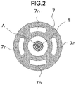
- FIG. 2 illustrates a cross section, being orthogonal to the axis line A, of the gas circuit breaker 100, the cross section being taken at a position along dotted-and-dashed line C1 of FIG. 1 .
- FIG. 3 illustrates a cross section, being orthogonal to the axis line A, of the gas circuit breaker 100, the cross section being taken at a position along dotted-and-dashed line C2 of FIG. 1 .
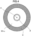
- FIG. 4 illustrates a cross section, being orthogonal to the axis line A, of the gas circuit breaker 100, the cross section being taken at a position along dotted-and-dashed line C3 of FIG. 1 .
- FIG. 1 also serves as a sectional view of a gas circuit breaker 101 (described later) according to the second embodiment.
- a tank 10 is made of, for example, a metal.
- An interior 10n of the tank 10 is where an insulating gas such as SF 6 gas is filled.
- a movable electrode 2 While being supported by a support cylinder 9, a movable electrode 2 is movable, by means of a drive mechanism (not illustrated), along the axis line A (indicated by a dotted-and-dashed line) of a stationary electrode 1.
- the axis line A serves the movable electrode 2 as a movement line along which the movable electrode 2 is connected to and separated from the stationary electrode 1, thus having an extension of this movement line.
- the stationary electrode 1 is electrically connected to one terminal (not illustrated) external to the tank 10.
- the movable electrode 2 is electrically connected to another terminal (not illustrated) external to the tank 10.
- a movable housing 3 encircling the movable electrode 2 is interlocked with the movable electrode 2 and has a nozzle 7 attached to its end.
- a cylinder 8 is attached covering the nozzle 7.
- a space enclosed by a wall surface of the nozzle 7 and a wall surface of the cylinder 8 defines a first thermal puffer chamber Tp.
- the movable housing 3 and the cylinder 8 are disposed in series along the axis line A while encircling the axis line A.
- the nozzle 7 includes intake ports 7n through which the insulating gas is taken into the first thermal puffer chamber Tp, and squirt holes 7u through which the insulating gas is squirted out of the first thermal puffer chamber Tp toward a position between the stationary electrode 1 and the movable electrode 2.
- the movable electrode 2, the movable housing 3, the nozzle 7, the cylinder 8, and the first thermal puffer chamber Tp interlock composing a movable part 21.
- a space enclosed with a wall surface of the movable housing 3 and a piston 4 that is fixed in position defines a mechanical puffer chamber Mp.
- a volume of the mechanical puffer chamber Mp varies as the movable part 21 is operated.
- a space between the movable housing 3 and the movable electrode 2 serves as a first suck-out port Mnu through which the insulating gas is taken into the mechanical puffer chamber Mp and is ejected out of the mechanical puffer chamber Mp.
- a cooling cylinder 5 is connected to the stationary electrode 1 and radiates generated heat of the stationary electrode 1 into the interior 10n of the tank 10.
- a stationary housing 6 is attached to the cooling cylinder 5 and fits over the movable housing 3 so that the connection between the stationary electrode 1 and the movable electrode 2 is supported.
- the stationary electrode 1, the cooling cylinder 5, and the stationary housing 6 compose a stationary part 11.
- the movable housing 3 is a first movable housing described in the claims
- the cylinder 8 is a second movable housing described in the claims.
- the intake ports 7n of the nozzle 7 are four in number and each intake port 7n opens in a direction parallel to the axis line A.
- the squirt holes 7u of the nozzle 7 are four in number and each squirt hole 7u opens from a lateral side of the axis line A toward the axis line A.
- an opening direction of each of the squirt holes 7u is arranged to intersect the axis line A in a plane that includes the opening direction of each squirt hole 7u and the axis line A.
- the first suck-out port Mnu opens in a direction parallel to the axis line A.
- the intake ports 7n illustrated in FIG. 1 face the first suck-out port Mnu.
- FIG. 5 illustrates time dependence of parameters during the operation of the gas circuit breaker 100;
- FIG. 5 (a) illustrates the time dependence of alternating current flowing between the stationary electrode 1 and the movable electrode 2; and
- FIG. 5 (b) illustrates varying distance between a leading end of the stationary electrode 1 and a leading end of the movable electrode 2 (interelectrode distance D).
- FIG. 6 is a sectional view illustrating a state of a main part of the gas circuit breaker 100 before a time T0 shown in FIG. 5 .
- FIG. 7 is a sectional view illustrating a state of the main part of the gas circuit breaker 100 from after a time T1 through a time T2 shown in FIG. 5 .
- FIG. 8 is a sectional view illustrating a state of the main part of the gas circuit breaker 100 from after the time T2 through the time T3 shown in FIG. 5 .
- FIG. 9 is a cross section taken at the position along dotted-and-dashed line C2 as with FIG. 3 , illustrating the state of the gas circuit breaker 100 from after the time T2 through the time T3.
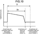
- FIG. 10 illustrates temperature distribution of the insulating gas along the axis line A at a fixed time that comes after the time T2 and before the time T3 with a vertical axis representing temperature of the insulating gas and with a horizontal axis representing positions along the axis line A.
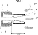
- FIG. 11 is a sectional view illustrating a state of the main part of the gas circuit breaker 100 after a time T4 shown in FIG. 5 .
- the alternating current flows steadily between the stationary electrode 1 and the movable electrode 2.
- the interelectrode distance D illustrated in FIG. 6 is shown as a distance between the leading end of the stationary electrode 1 and the leading end of the movable electrode 2. With the stationary electrode 1 and the movable electrode 2 fitted together and touching each other at their respective leading ends, the interelectrode distance D is defined as a negative value.
- the interelectrode distance D approximates a value of zero.
- the interelectrode distance D is defined as a positive value.
- a distance Dt is a length component along the axis line A between the leading end of the movable electrode 2 and center of the squirt holes 7u of the nozzle 7.
- the interelectrode distance D is a negative value, and the stationary electrode 1 and the movable electrode 2 touch each other, the alternating current directly flows between the stationary electrode 1 and the movable electrode 2 without via an arc discharge E.
- the interelectrode distance D becomes a positive value, and the stationary electrode 1 and the movable electrode 2 become separated. Therefore, the current flows between the stationary electrode 1 and the movable electrode 2 through the arc discharge E.
- the arc discharge E between the stationary electrode 1 and the movable electrode 2 has a high temperature.
- the arc discharge E has a discharge direction along the axis line A.
- the insulating gas near the arc discharge E is heated, and pressure of the insulating gas increases. Accordingly, an insulating gas flow Se having a direction toward the movable housing 3 is generated in the vicinity of the arc discharge E.
- the gas flow Se branches into: a gas flow Smn that has a direction toward the mechanical puffer chamber Mp through the first suck-out port Mnu; and gas flow Stn that has a direction toward the first thermal puffer chamber Tp through the intake ports 7n.
- Amount of heat generated by the arc discharge E increases with an increasing absolute value of the current.
- the alternating current reaches maximum absolute values (a minimum current value and a maximum current value), so that the amount of heat generated by the arc discharge E increases sharply. Accordingly, the pressure of the insulating gas increases sharply, and the gas flow Se also increases sharply.
- the gas flow Smn and the gas flow Stn similarly increase sharply. With the gas flow Smn entering the mechanical puffer chamber Mp through the first suck-out port Mnu, internal pressure of the mechanical puffer chamber Mp increases sharply. With the gas flowStn entering the first thermal puffer chamber Tp through the intake ports 7n, internal pressure of the first thermal puffer chamber Tp also increases sharply.
- FIGS. 5 and 8 As the gas circuit breaker 100 progresses with the current interruption operation, the interelectrode distance D increases further. In other words, the volume of the mechanical puffer chamber Mp is compressed in proportion as the interelectrode distance D increases.
- the gas flow Smu is ejected through the first suck-out port Mnu toward the intake ports 7n. For this reason, a leakage of the insulating gas through each of the intake ports 7n toward the first suck-out port Mnu is suppressed. Accordingly, volume of the gas flow Stu that squirts out through the squirt holes 7u of the nozzle 7 advantageously increases.
- the interelectrode distance D increases further and becomes greater than the distance Dt.
- the squirt holes 7u of the nozzle 7 pass the leading end of the stationary electrode 1. Therefore, during the movement of the movable part 21, the gas flow Stu strike the arc discharge E so that the arc discharge E is struck from sideways relative to the discharge direction.
- the gas flow Stu strikes the arc discharge E through the four squirt holes 7u.
- the arc discharge E is struck from sideways by the gas flow Stu squirting out through the four squirt holes 7u toward the arc discharge E.
- the temperature of the insulating gas is relatively high between a position of the leading end of the movable electrode 2 and a position near the center of the squirt holes 7u, but is drastically lower on a side of the stationary electrode 1 with respect to the center of the squirt holes 7u.
- This phenomenon is due to the fact that the gas flow Stu strikes a particular location of the arc discharge E depending on the displacement of the interelectrode D, causing a temperature drop of the insulating gas at the location, which is struck by the gas flows Stu.
- the interelectrode distance D reaches a maximum value Dmax, and the operation of the movable part 21 stops. This means that the current interruption operation is complete.
- the gas flow Stn that is branched off from the gas flow Se is taken into the first thermal puffer chamber Tp through the intake ports 7n without passing through the mechanical puffer chamber Mp.
- the internal pressure of the first thermal puffer chamber Tp increases with the arrival of the gas flows Stn, and accordingly, the gas flow Stu strikes the arc discharge E through the squirt holes 7u from after the time T2 through the time T3.
- the gas flow Smn branched off from the gas flow Se enters the mechanical puffer chamber Mp without passing through the first thermal puffer chamber Tp from after the time T1 through the time T2. With the volume of the mechanical puffer chamber Mp compressed by the piston 4, the gas flow Smu strikes the arc discharge E from after the time T2 through the time T3.
- the gas flow Stu from the first thermal puffer chamber Tp and the gas flow Smu from the mechanical puffer chamber Mp strike the arc discharge E from after the time T2 through the time T3, and by the time T4 the operation of the movable part 21 stops, the arc discharge E is quenched to complete the current interruption operation.
- the first thermal puffer chamber Tp does not serve as a passage for the mechanically compressed insulating gas that comes from the mechanical puffer chamber Mp, and the pressure rise of the insulating gas in the mechanical puffer chamber Mp is not inhibited. Moreover, flow speed of the gas flow Smu from the mechanical puffer chamber Mp to the arc discharge E does not slow down, so that there is no decline in interruption performance of the gas circuit breaker 100.
- the first thermal puffer chamber Tp does not serve as the passage for the mechanically compressed insulating gas that comes from the mechanical puffer chamber Mp, and the pressure rise of the insulating gas in the mechanical puffer chamber Mp is not inhibited by a leakage of the insulating gas to the first thermal puffer chamber Tp.
- the first embodiment provides higher current interruption performance regardless of magnitude of the current value. Therefore, the gas circuit breaker 100 capable of handling a wide range of current values is provided.
- the intake ports 7n for the first thermal puffer chamber Tp are disposed in a different position from the squirt holes 7u, so that compared to when the same ports or holes are used for the intake of the insulating gas and the ejection of the insulating gas, no time is required for switching between the intake of the insulating gas and the ejection of the insulating gas. In other words, the time between the intake of the insulating gas and the ejection of the insulating gas is shortened as compared to the conventional gas circuit breaker.
- the gas flow Smu is ejected through the first suck-out port Mnu toward the intake ports 7n. For this reason, the leakage of the insulating gas through each of the intake ports 7n toward the first suck-out port Mnu is suppressed. Accordingly, volume of the gas flow Stu that squirts out through the squirt holes 7u of the nozzle 7 is advantageously increased.
- the gas circuit breaker 100 can be downsized compared to when the first thermal puffer chamber Tp and the mechanical puffer chamber Mp are disposed side by side in a direction perpendicular to the axis line A.
- each squirt hole 7u is arranged to intersect the axis line A in the plane that includes the opening direction of each squirt hole 7u and the axis line AA.
- an opening direction v1, v2, v3, or v4 of each of squirt holes 7v is not arranged to intersect the axis line A in the same plane as the axis line A.
- the opening direction v1, v2, v3, or v4 of each squirt hole 7v and the axis line A are arranged in twisted positions from each other in the same plane. Arranging the squirt holes 7v in this manner enables the gas flows Stu and the gas flow Smu to efficiently strike the arc discharge E for quenching the arc discharge E even when the arc discharge E does not cross the axis line A.
- FIG. 1 serves as the sectional view of the gas circuit breaker 100 according to first embodiment and also as the sectional view of the gas circuit breaker 101 according to the second embodiment.
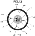
- FIG. 12 illustrates a cross section, being orthogonal to the axis line A of the gas circuit breaker 101, the cross section being taken at the position along dotted-and-dashed line C2 of FIG. 1 .
- the four squirt holes 7v1 to 7v4 open from the lateral side of the axis line A.
- the opening direction v1 of the squirt hole 7v1 is not arranged in the same plane as the axis line A and is not arranged to intersect the axis line A. In other words, the opening direction v1 of the squirt hole 7v1 and the axis line A are arranged in twisted positions from each other.
- the opening direction v2 of the squirt hole 7v2 and the axis line A are arranged in twisted positions from each other; the opening direction v3 of the squirt hole 7v3 and the axis line A are arranged in twisted positions from each other; and the opening direction v4 of the squirt hole 7v4and the axis line A are arranged in twisted positions from each other.
- the opening direction v1 of the squirt hole 7v1, the opening direction v2 of the squirt hole 7v2, the opening direction v3 of the squirt hole 7v3, and the opening direction v4 of the squirt hole 7v4 are arranged to be shifted from the axis line A of the stationary electrode 1 when projected onto a plane having the axis line A of the stationary electrode 1 as a normal.
- Such an arrangement enables the gas flows Stu to efficiently strike the arc discharge E for quenching the arc discharge E even when the arc discharge E does not cross the axis line A, but extends along a path that does not include the axis line A.
- the second embodiment provides higher current interruption performance regardless of magnitude of the current value similarly as the first embodiment. Therefore, the gas circuit breaker 101 applicable to a wide range of current values can be provided.
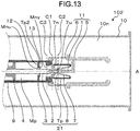
- FIG. 13 is a sectional view of a gas circuit breaker 102 according to the third embodiment of the present invention.
- the present embodiment differs from the first embodiment in that a second thermal puffer chamber Tp2 is provided further.
- parts that are similar or equivalent to those of the first embodiment have the same numerals and references that are seen in FIGS. 1 to 12 and thus are not described in detail.
- a partition 12 is formed on an inner wall surface of the movable housing 3, dividing an internal space of the movable housing 3 into the mechanical puffer chamber Mp and the second thermal puffer chamber Tp2.
- the mechanical puffer chamber Mp is a space enclosed by the partition 12, the movable housing 3, the piston 4, and the movable electrode 2.
- the second thermal puffer chamber Tp2 is a space enclosed with the partition 12, the movable housing 3, and the movable electrode 2.
- the mechanical puffer chamber Mp, the second thermal puffer chamber Tp2, and the first thermal puffer chamber Tp are disposed in series along the axis line A.
- the mechanical puffer chamber Mp is disposed on an opposite side of the first thermal puffer chamber Tp sandwiching the second thermal puffer chamber Tp2 in-between along the axis line A.
- the second thermal puffer chamber Tp2 is disposed between the mechanical puffer chamber Mp and the first thermal puffer chamber Tp along the axis line A.
- the partition 12 is a disk-shaped part having a through hole in its center.
- the movable electrode 2 is passed through the through hole of the partition 12. A diameter of the through hole of the partition 12 is larger than an outside diameter of the movable electrode 2. Therefore, a clearance is formed between the partition 12 and the movable electrode 2.
- the through hole of the partition 12 has this clearance as a portion that does not engage in the passage of the movable electrode 2, so that the clearance is the first suck-out port Mnu serving as a communication between the mechanical puffer chamber Mp and the second thermal puffer chamber Tp2.
- the first suck-out port Mnu serves as a passage for an insulating gas.
- the insulating gas flows out of the second thermal puffer chamber Tp2 into the mechanical puffer chamber Mp through the first suck-out port Mnu.
- the insulating gas also flows out of the mechanical puffer chamber Mp into the second thermal puffer chamber Tp2 through the first suck-out port Mnu.
- An annular check valve 13 is disposed on an outer peripheral surface of the movable electrode 2.
- the check valve 13 has, in its center, a through hole that the movable electrode 2 is passed through.
- the check valve 13 is disposed inside the second thermal puffer chamber Tp2.
- the check valve 13 is movable relative to the movable part 21 along the axis line A.
- the check valve 13 blocks the first suck-out port Mnu and opens the first suck-out port Mnu.
- the first suck-out port Mnu being blocked by the check valve 13 is hereinafter referred to as "the first suck-out port Mnu in the blocked state”; and the first suck-out port Mnu being opened by the check valve 13 is hereinafter referred to as "the first suck-out port Mnu in the opened state”.
- a second suck-out port Mnv is formed on an opposite side of the partition 12 sandwiching the second thermal puffer chamber Tp2 in-between.
- the second suck-out port Mnv serves as a passage for the insulating gas.
- the insulating gas flows into the second thermal puffer chamber Tp2 through the second suck-out port Mnv.
- the insulating gas also flows out of the second thermal puffer chamber Tp2 through the second suck-out port Mnv.
- the second suck-out port Mnv is formed between the movable electrode 2 and a part of the nozzle 7 that touches the inner wall surface of the movable housing 3.
- the second suck-out port Mnv may be formed between the inner wall surface of the movable housing 3 and the movable electrode 2. It is to be noted that the first thermal puffer chamber Tp is disposed in a different position from a passage for the insulating gas that heads from the mechanical puffer chamber Mp toward the arc discharge E.
- the arc discharge E that is generated in the high-current interruption has higher thermal energy and thus sufficiently increases pressure of the insulating gas in the second thermal puffer chamber Tp2.
- the pressure of the insulating gas in the second thermal puffer chamber Tp2 is higher than a pressure of the insulating gas in the mechanical puffer chamber Mp.
- the check valve 13 moves toward the mechanical puffer chamber Mp.
- the check valve 13 comes into contact with a surface of the partition 12 that faces the second thermal puffer chamber Tp2, thus blocking the first suck-out port Mnu.
- the insulating gas surrounding the arc discharge E flows into the first thermal puffer chamber Tp through the intake ports 7n and into the second thermal puffer chamber Tp2 through the second suck-out port Mnv with the first suck-out port Mnu in the blocked state. Accordingly, the insulating gas has an increased pressure in the first thermal puffer chamber Tp and an increased pressure in the second thermal puffer chamber Tp2. From after the time T2 through the time T3 shown in FIG.
- the insulating gas in the second thermal puffer chamber Tp2 passes through the second suck-out port Mnv and is blown onto the arc discharge E; and the insulating gas in the first thermal puffer chamber Tp passes through the squirt holes 7u and is blown onto the arc discharge E. With the insulating gases blown onto the arc discharge E, the arc discharge E is quenched.
- the arc discharge E that is generated in the low-current interruption has lower thermal energy and thus does not sufficiently increase the pressure of the insulating gas in the second thermal puffer chamber Tp2.
- the pressure of the insulating gas in the mechanical puffer chamber Mp is higher than the pressure of the insulating gas in the second thermal puffer chamber Tp2. Therefore, the check valve 13 moves away from the mechanical puffer chamber Mp.
- the check valve 13 leaves the partition 12, thus opening the first suck-out port Mnu.
- the insulating gas surrounding the arc discharge E flows into the first thermal puffer chamber Tp through the intake ports 7n and into the second thermal puffer chamber Tp2 through the second suck-out port Mnv with the first suck-out port Mnu in the opened state. Accordingly, the insulating gas has an increased pressure in the first thermal puffer chamber Tp and an increased pressure in the second thermal puffer chamber Tp2. From after the time T1 through the time T2 shown in FIG. 5 , the insulating gas in the mechanical puffer chamber Mp also flows into the second thermal puffer chamber Tp2 through the first suck-out port Mnu that is in the opened state. From after the time T2 through the time T3 shown in FIG.
- the insulating gas that has flowed out of the mechanical puffer chamber Mp into the second thermal puffer chamber Tp2 through the first suck-out port Mnu is blown onto the arc discharge E through the second suck-out port Mnv.
- the second thermal puffer chamber Tp2 serves as a passage for the insulating gas heading from the mechanical puffer chamber Mp toward the arc discharge E. From after the time T2 through the time T3 shown in FIG.
- the insulating gas in the first thermal puffer chamber Tp also passes through the squirt holes 7u and is blown onto the arc discharge E with the first suck-out port Mnu in the opened state. With the insulating gases blown onto the arc discharge E, the arc discharge E is quenched.
- thermal puffer chamber volume is determined by required high-current interruption performance of the gas circuit breaker 102.
- the two thermal puffer chambers are provided as the first thermal puffer chamber Tp and the second thermal puffer chamber Tp2. This enables the thermal puffer chamber volume, which is required to achieve the required high-current interruption performance of the gas circuit breaker 102, to be divided between the first thermal puffer chamber Tp and the second thermal puffer chamber Tp2.
- the second thermal puffer chamber Tp2 is enabled to have volume decreased as much as a volume of the first thermal puffer chamber Tp.
- the gas circuit breaker 102 can be downsized.
- Low-current interruption performance of the gas circuit breaker 102 is determined by a compressibility of the insulating gas in the mechanical puffer chamber Mp and the second thermal puffer chamber Tp2. Specifically, the higher the compressibility of the insulating gas in the mechanical puffer chamber Mp and the second thermal puffer chamber Tp2, the better the low-current interruption performance of the gas circuit breaker 102.
- the second thermal puffer chamber Tp2 is enabled to have the volume decreased as much as the volume of the first thermal puffer chamber Tp in the present embodiment, the compressibility of the insulating gas in the second thermal puffer chamber Tp2 is higher than when the thermal puffer chamber is provided only in the passage for the insulating gas that heads from the mechanical puffer chamber Mp toward the arc discharge E. Therefore, this enables the gas circuit breaker 102 to have the improved low-current interruption performance.
- the nozzle 7 may be made of an ablative material.
- the ablative material is evaporated by heat of the gas flows Stn that enter the first thermal puffer chamber Tp respectively through the intake ports 7n. Accordingly, the internal pressure of the first thermal puffer chamber Tp increases, and the gas flow Stu has an increased pressure when squirting out through the squirt holes 7u.
- the highpressure gas flow Stu is enabled to strike and efficiently quench the arc discharge E.
- the first thermal puffer chamber Tp may be formed using an ablative material, and further an ablative material may be disposed inside the first thermal puffer chamber Tp. Even in these cases, the internal pressure of the first thermal puffer chamber Tp increases, and the gas flow Stu has an increased pressure when squirting out through the squirt holes 7u.
- the ablative material include polytetrafluoroethylene (PTFE) and a perfluoroalkylvinyl ether copolymer (PFA).
- PTFE polytetrafluoroethylene
- PFA perfluoroalkylvinyl ether copolymer
- ablative material is at least one compound selected from the group consisting of a perfluoroether polymer, a fluoroelastomer, and a 4-vinyloxy-1-butene (BVE) cyclized polymer.
- the nozzle 7 has the four intake ports 7n and the four squirt holes 7u.
- the number of intake ports 7n and the number of squirt holes 7u are not limiting in the present invention and are determined as appropriate when the gas circuit breakers 100 to 102 are designed.
- each squirt hole 7u is arranged to intersect the axis line A in a plane that includes the opening direction of each squirt hole 7u and the axis line A.
- the opening direction of each squirt hole 7v and the axis line A are arranged in twisted positions from each other in a plane that includes the opening direction of each squirt hole 7u and the axis line A.
- the opening direction of each squirt hole (7u, 7v) is not limiting in the present invention.
- the nozzle 7 may include both the squirt hole 7u that is arranged to intersect the axis line A, and the squirt hole 7v that is arranged not to intersect the axis line A.
Landscapes
- Circuit Breakers (AREA)
Abstract
Description
- The present invention relates to a gas circuit breaker that performs an opening operation for power interruption and a closing operation for power supply.
- A conventional gas circuit breaker includes a mechanical compression chamber (mechanical puffer chamber) and a thermally pressurizing chamber (thermal puffer chamber). The mechanical puffer chamber includes a mechanism that mechanically compresses an insulating gas in the mechanical puffer chamber and blows, in current interruption, the compressed insulating gas onto an arc discharge generated between contacts. In a description below, an area where the arc discharge is occurring is also referred to simply as "arc discharge". The thermal puffer chamber plays a role of pressurizing the insulating gas by means of thermal energy of the arc discharge and blowing the pressurized insulating gas onto the arc discharge .
- When the arc discharge is generated during the current interruption, the insulating gas blown from the mechanical puffer chamber and the insulating gas blown from the thermal puffer chamber quench the arc discharge by removing ionized gases produced by the arc discharge, thus completing the current interruption (refer to, for example, Patent Literature 1).
- Patent Literature 1:
Japanese Patent Application Laid-open No. 2003-297200 - Current interruption performance of such a conventional gas circuit breaker depends greatly on the pressure of the insulating gas that is blown onto the arc discharge. This means that in order to ensure the current interruption performance, the pressure of the insulating gas needs to be increased in the mechanical puffer chamber and in the thermal puffer chamber.
- However, when a relatively low current flowing in the gas circuit breaker is to be interrupted (in a low-current interruption duty), an arc discharge generated in the current interruption has low thermal energy. Therefore, the pressure of the insulating gas may not become sufficiently high in the thermal puffer chamber.
- In the conventional gas circuit breaker, the thermal puffer chamber is disposed in a passage for the insulating gas that comes from the mechanical puffer chamber and thus can inhibit, in the low -current interruption duty, the pressure rise of the insulating gas in the mechanical puffer chamber. Moreover, the gas flows from the mechanical puffer chamber at a reduced speed toward the arc discharge. This may contribute to a decline in the interruption performance of the gas circuit breaker.
- In other words, the conventional gas circuit breaker problematically has deteriorated current interruption performance in the low -current interruption duty.
- The present invention has been made to solve these problems, and an object of the present invention is to provide a gas circuit breaker that is capable of suppressing a decline in current interruption performance even in a low-current interruption duty.
- A gas circuit breaker according to the present invention includes a tank filled with an insulating gas. The tank comprises: a stationary electrode that is conductive; a movable electrode configured to be movable along an axis line of the stationary electrode and to be connectable to and separable from the stationary electrode; a first movable housing configured to be interlocked with the movable electrode and to encircle the axis line; a piston configured to form a mechanical puffer chamber with the first movable housing; a second movable housing configured to be interlocked with the movable electrode and to be positioned in series with the first movable housing along the axis line; and a nozzle configured to form a first thermal puffer chamber with the second movable housing. The first movable housing includes a first suck-out port configured to allow the insulating gas to be taken into the mechanical puffer chamber and to allow the insulating gas to be ejected out of the mechanical puffer chamber. The nozzle includes an intake port configured to allow the insulating gas to be taken into the first thermal puffer chamber, and a squirt hole configured to allow the insulating gas to be squirted out of the first thermal puffer chamber toward a position between the stationary electrode and the movable electrode.
- The gas circuit breaker according to the present invention is capable of suppressing a decline in current interruption performance even in a low-current interruption duty and thus has higher current interruption performance.
-
-
FIG. 1 is a sectional view of agas circuit breaker 100 according to a first embodiment of the present invention.FIG. 1 also serves as a sectional view of a gas circuit breaker 101 according to a second embodiment of the present invention. -
FIG. 2 illustrates a cross section of thegas circuit breaker 100 that is taken at a position along dotted-and-dashed line C1. -
FIG. 3 illustrates a cross section of thegas circuit breaker 100 that is taken at a position along dotted-and-dashed line C2. -
FIG. 4 illustrates a cross section of thegas circuit breaker 100 that is taken at a position along dotted-and-dashed line C3. -
FIG. 5 illustrates time dependence of parameters during operation of thegas circuit breaker 100 with part (a) ofFIG. 5 illustrating the time dependence of alternating current flowing between astationary electrode 1 and amovable electrode 2 and with part (b) ofFIG. 5 illustrating varying distance between a leading end of thestationary electrode 1 and a leading end of the movable electrode 2 (interelectrode distance). -
FIG. 6 is a sectional view illustrating a state of a main part of thegas circuit breaker 100 before a time T0. -
FIG. 7 is a sectional view illustrating a state of the main part of thegas circuit breaker 100 from after a time T1 through a time T2. -
FIG. 8 is a sectional view illustrating a state of the main part of thegas circuit breaker 100 from after the time T2 through the time T3. -
FIG. 9 is a cross section taken at the position along dotted-and-dashed line C2, illustrating the state of thegas circuit breaker 100 from after the time T2 through the time T3. -
FIG. 10 illustrates temperature distribution of an insulating gas along an axis line A at a fixed time that comes after the time T2 and before the time T3. -
FIG. 11 is a sectional view illustrating a state of the main part of thegas circuit breaker 100 after a time T4. -
FIG. 12 illustrates a cross section of the gas circuit breaker 101 according to the second embodiment of the present invention, the cross section being taken at the position along dotted-and-dashed line C2. -
FIG. 13 is a sectional view of agas circuit breaker 102 according to a third embodiment of the present invention. - With reference to the drawings, a detailed description is hereinafter provided of gas circuit breakers according to embodiments of the present invention. It is to be noted that these embodiments are not restrictive of the present invention.
-
FIGS. 1 to 11 illustrate the first embodiment of the present invention. - With reference to
FIGS. 1 to 4 , a description is provided of structure of agas circuit breaker 100 according to the first embodiment of the present invention. With reference toFIGS. 5 to 11 , a description is provided of current interruption operation of thegas circuit breaker 100. - The structure of the
gas circuit breaker 100 according to the first embodiment is described first with reference toFIGS. 1 to 4 . -
FIG. 1 is a sectional view illustrating a closed state of thegas circuit breaker 100 according to the first embodiment of the present invention, the section being a plane including an axis line A that is described later.FIG. 2 illustrates a cross section, being orthogonal to the axis line A, of thegas circuit breaker 100, the cross section being taken at a position along dotted-and-dashed line C1 ofFIG. 1 .FIG. 3 illustrates a cross section, being orthogonal to the axis line A, of thegas circuit breaker 100, the cross section being taken at a position along dotted-and-dashed line C2 ofFIG. 1 .FIG. 4 illustrates a cross section, being orthogonal to the axis line A, of thegas circuit breaker 100, the cross section being taken at a position along dotted-and-dashed line C3 ofFIG. 1 . - It is to be noted that
FIG. 1 also serves as a sectional view of a gas circuit breaker 101 (described later) according to the second embodiment. - Reference is made to
FIG. 1 . Atank 10 is made of, for example, a metal. An interior 10n of thetank 10 is where an insulating gas such as SF6 gas is filled. While being supported by asupport cylinder 9, amovable electrode 2 is movable, by means of a drive mechanism (not illustrated), along the axis line A (indicated by a dotted-and-dashed line) of astationary electrode 1. Thus themovable electrode 2 is separable from thestationary electrode 1. In other words, the axis line A serves themovable electrode 2 as a movement line along which themovable electrode 2 is connected to and separated from thestationary electrode 1, thus having an extension of this movement line. - The
stationary electrode 1 is electrically connected to one terminal (not illustrated) external to thetank 10. Similarly, themovable electrode 2 is electrically connected to another terminal (not illustrated) external to thetank 10. - A
movable housing 3 encircling themovable electrode 2 is interlocked with themovable electrode 2 and has anozzle 7 attached to its end. Acylinder 8 is attached covering thenozzle 7. A space enclosed by a wall surface of thenozzle 7 and a wall surface of thecylinder 8 defines a first thermal puffer chamber Tp. In other words, themovable housing 3 and thecylinder 8 are disposed in series along the axis line A while encircling the axis line A. - The
nozzle 7 includesintake ports 7n through which the insulating gas is taken into the first thermal puffer chamber Tp, and squirtholes 7u through which the insulating gas is squirted out of the first thermal puffer chamber Tp toward a position between thestationary electrode 1 and themovable electrode 2. Themovable electrode 2, themovable housing 3, thenozzle 7, thecylinder 8, and the first thermal puffer chamber Tp interlock composing amovable part 21. - A space enclosed with a wall surface of the
movable housing 3 and apiston 4 that is fixed in position defines a mechanical puffer chamber Mp. This means that the first thermal puffer chamber Tp and the mechanical puffer chamber Mp are disposed in series along the axis line A. As described in detail later, a volume of the mechanical puffer chamber Mp varies as themovable part 21 is operated. - A space between the
movable housing 3 and themovable electrode 2 serves as a first suck-out port Mnu through which the insulating gas is taken into the mechanical puffer chamber Mp and is ejected out of the mechanical puffer chamber Mp. - A
cooling cylinder 5 is connected to thestationary electrode 1 and radiates generated heat of thestationary electrode 1 into the interior 10n of thetank 10. Astationary housing 6 is attached to thecooling cylinder 5 and fits over themovable housing 3 so that the connection between thestationary electrode 1 and themovable electrode 2 is supported. - The
stationary electrode 1, thecooling cylinder 5, and thestationary housing 6 compose astationary part 11. - The
movable housing 3 is a first movable housing described in the claims, and thecylinder 8 is a second movable housing described in the claims. - Reference is made to
FIG. 2 . Theintake ports 7n of thenozzle 7 are four in number and eachintake port 7n opens in a direction parallel to the axis line A. - Next, reference is made to
FIG. 3 . The squirt holes 7u of thenozzle 7 are four in number and eachsquirt hole 7u opens from a lateral side of the axis line A toward the axis line A. In other words, an opening direction of each of thesquirt holes 7u is arranged to intersect the axis line A in a plane that includes the opening direction of eachsquirt hole 7u and the axis line A. - Reference is also made to
FIG. 4 . The first suck-out port Mnu opens in a direction parallel to the axis line A. Theintake ports 7n illustrated inFIG. 1 face the first suck-out port Mnu. - With reference to
FIGS. 5 to 11 , the current interruption operation of thegas circuit breaker 100 is described next. -
FIG. 5 illustrates time dependence of parameters during the operation of thegas circuit breaker 100;FIG. 5 (a) illustrates the time dependence of alternating current flowing between thestationary electrode 1 and themovable electrode 2; andFIG. 5 (b) illustrates varying distance between a leading end of thestationary electrode 1 and a leading end of the movable electrode 2 (interelectrode distance D). -
FIG. 6 is a sectional view illustrating a state of a main part of thegas circuit breaker 100 before a time T0 shown inFIG. 5 .FIG. 7 is a sectional view illustrating a state of the main part of thegas circuit breaker 100 from after a time T1 through a time T2 shown inFIG. 5 . -
FIG. 8 is a sectional view illustrating a state of the main part of thegas circuit breaker 100 from after the time T2 through the time T3 shown inFIG. 5 .FIG. 9 is a cross section taken at the position along dotted-and-dashed line C2 as withFIG. 3 , illustrating the state of thegas circuit breaker 100 from after the time T2 through the time T3.FIG. 10 illustrates temperature distribution of the insulating gas along the axis line A at a fixed time that comes after the time T2 and before the time T3 with a vertical axis representing temperature of the insulating gas and with a horizontal axis representing positions along the axis line A. -
FIG. 11 is a sectional view illustrating a state of the main part of thegas circuit breaker 100 after a time T4 shown inFIG. 5 . - With reference to
FIGS. 5 and 6 , a description is provided of the state before the time T0, that is to say, before thegas circuit breaker 100 performs a current interruption. - Before the time T0, the alternating current flows steadily between the
stationary electrode 1 and themovable electrode 2. - The interelectrode distance D illustrated in
FIG. 6 is shown as a distance between the leading end of thestationary electrode 1 and the leading end of themovable electrode 2. With thestationary electrode 1 and themovable electrode 2 fitted together and touching each other at their respective leading ends, the interelectrode distance D is defined as a negative value. - As the
gas circuit breaker 100 progresses with the current interruption operation (as themovable part 21 moves leftward in the drawing), the interelectrode distance D approximates a value of zero. When the leading end of themovable electrode 2 no longer touches the leading end of thestationary electrode 1 with further progress in the current interruption operation of thegas circuit breaker 100, the interelectrode distance D is defined as a positive value. - A distance Dt is a length component along the axis line A between the leading end of the
movable electrode 2 and center of thesquirt holes 7u of thenozzle 7. - Before the time T1, the interelectrode distance D is a negative value, and the
stationary electrode 1 and themovable electrode 2 touch each other, the alternating current directly flows between thestationary electrode 1 and themovable electrode 2 without via an arc discharge E. - After the time T1, the interelectrode distance D becomes a positive value, and the
stationary electrode 1 and themovable electrode 2 become separated. Therefore, the current flows between thestationary electrode 1 and themovable electrode 2 through the arc discharge E. - Since the
piston 4 is fixed, the volume of the mechanical puffer chamber Mp decreases in proportion as the interelectrode distance D varies. This means that the insulating gas is compressed in the mechanical puffer chamber Mp. - With reference to
FIGS. 5 and7 , a description is provided next of the state of thegas circuit breaker 100 from after the time T2 through the time T3 after themovable part 21 has moved leftward in the drawing in the current interruption operation that has started at the time T0 and has caused the interelectrode distance D to become the value of zero at the time T1. - In the description, the arc discharge E between the
stationary electrode 1 and themovable electrode 2 has a high temperature. In addition, the arc discharge E has a discharge direction along the axis line A. - Because of the high temperature, the insulating gas near the arc discharge E is heated, and pressure of the insulating gas increases. Accordingly, an insulating gas flow Se having a direction toward the
movable housing 3 is generated in the vicinity of the arc discharge E. - The gas flow Se branches into: a gas flow Smn that has a direction toward the mechanical puffer chamber Mp through the first suck-out port Mnu; and gas flow Stn that has a direction toward the first thermal puffer chamber Tp through the
intake ports 7n. - Amount of heat generated by the arc discharge E increases with an increasing absolute value of the current. Between the times T1 and T2, the alternating current reaches maximum absolute values (a minimum current value and a maximum current value), so that the amount of heat generated by the arc discharge E increases sharply. Accordingly, the pressure of the insulating gas increases sharply, and the gas flow Se also increases sharply.
- The gas flow Smn and the gas flow Stn similarly increase sharply. With the gas flow Smn entering the mechanical puffer chamber Mp through the first suck-out port Mnu, internal pressure of the mechanical puffer chamber Mp increases sharply. With the gas flowStn entering the first thermal puffer chamber Tp through the
intake ports 7n, internal pressure of the first thermal puffer chamber Tp also increases sharply. - With reference to
FIG. 5 andFIGS. 8 to 10 , a description is provided of the state of thegas circuit breaker 100 from after the time T2 through the time T3. - Reference is made to
FIGS. 5 and8 . As thegas circuit breaker 100 progresses with the current interruption operation, the interelectrode distance D increases further. In other words, the volume of the mechanical puffer chamber Mp is compressed in proportion as the interelectrode distance D increases. - With the sharp pressure rise in the mechanical puffer chamber Mp from after the time T1 through the time T2 and with the compressed volume of the mechanical puffer chamber Mp, a gas flow Smu strikes the arc discharge E through the first suck-out port Mnu.
- Similarly, with the sharp pressure rise in the first thermal puffer chamber Tp from after the time T1 through the time T2, gas flow Stu squirts out through the
squirt holes 7u of thenozzle 7 toward the arc discharge E. - Since the first suck-out port Mnu for the mechanical puffer chamber Mp faces the
intake ports 7n of thenozzle 7, the gas flow Smu is ejected through the first suck-out port Mnu toward theintake ports 7n. For this reason, a leakage of the insulating gas through each of theintake ports 7n toward the first suck-out port Mnu is suppressed. Accordingly, volume of the gas flow Stu that squirts out through thesquirt holes 7u of thenozzle 7 advantageously increases. - The interelectrode distance D increases further and becomes greater than the distance Dt. In other words, the
squirt holes 7u of thenozzle 7 pass the leading end of thestationary electrode 1. Therefore, during the movement of themovable part 21, the gas flow Stu strike the arc discharge E so that the arc discharge E is struck from sideways relative to the discharge direction. - Reference is made to
FIG. 9 . The gas flow Stu strikes the arc discharge E through the foursquirt holes 7u. The arc discharge E is struck from sideways by the gas flow Stu squirting out through the foursquirt holes 7u toward the arc discharge E. - Reference is made to
FIG. 10 . The temperature of the insulating gas is relatively high between a position of the leading end of themovable electrode 2 and a position near the center of thesquirt holes 7u, but is drastically lower on a side of thestationary electrode 1 with respect to the center of thesquirt holes 7u. This phenomenon is due to the fact that the gas flow Stu strikes a particular location of the arc discharge E depending on the displacement of the interelectrode D, causing a temperature drop of the insulating gas at the location, which is struck by the gas flows Stu. - The gas flows Smu and Stu striking the arc discharge E cause ions and electrons generated by the arc discharge E to dissipate, and the arc discharge E rapidly attenuates. At the time T3, when the alternating current becomes zero, the arc discharge E is quenched.
- With reference to
FIGS. 5 and11 , a description is provided of the state of thegas circuit breaker 100 from after T4, which comes after the time T3. - At the time T4, the interelectrode distance D reaches a maximum value Dmax, and the operation of the
movable part 21 stops. This means that the current interruption operation is complete. - According to the first embodiment, from after the time T1 through the time T2, the gas flow Stn that is branched off from the gas flow Se is taken into the first thermal puffer chamber Tp through the
intake ports 7n without passing through the mechanical puffer chamber Mp. The internal pressure of the first thermal puffer chamber Tp increases with the arrival of the gas flows Stn, and accordingly, the gas flow Stu strikes the arc discharge E through thesquirt holes 7u from after the time T2 through the time T3. - The gas flow Smn branched off from the gas flow Se, on the other hand, enters the mechanical puffer chamber Mp without passing through the first thermal puffer chamber Tp from after the time T1 through the time T2. With the volume of the mechanical puffer chamber Mp compressed by the
piston 4, the gas flow Smu strikes the arc discharge E from after the time T2 through the time T3. - In other words, the gas flow Stu from the first thermal puffer chamber Tp and the gas flow Smu from the mechanical puffer chamber Mp strike the arc discharge E from after the time T2 through the time T3, and by the time T4 the operation of the
movable part 21 stops, the arc discharge E is quenched to complete the current interruption operation. - Therefore, unlike the conventional gas circuit breaker, the first thermal puffer chamber Tp does not serve as a passage for the mechanically compressed insulating gas that comes from the mechanical puffer chamber Mp, and the pressure rise of the insulating gas in the mechanical puffer chamber Mp is not inhibited. Moreover, flow speed of the gas flow Smu from the mechanical puffer chamber Mp to the arc discharge E does not slow down, so that there is no decline in interruption performance of the
gas circuit breaker 100. - This means that even in a low-current interruption duty, extinction of the arc discharge E is attainable with the gas flow Stu and the gas flow Smu that efficiently strike the arc discharge E without inhibitions of the pressure rise of the insulating gas in the first thermal puffer chamber Tp and in the mechanical puffer chamber Mp.
- Even in interruption of a relatively higher current, the first thermal puffer chamber Tp does not serve as the passage for the mechanically compressed insulating gas that comes from the mechanical puffer chamber Mp, and the pressure rise of the insulating gas in the mechanical puffer chamber Mp is not inhibited by a leakage of the insulating gas to the first thermal puffer chamber Tp.
- In other words, the first embodiment provides higher current interruption performance regardless of magnitude of the current value. Therefore, the
gas circuit breaker 100 capable of handling a wide range of current values is provided. - The
intake ports 7n for the first thermal puffer chamber Tp are disposed in a different position from thesquirt holes 7u, so that compared to when the same ports or holes are used for the intake of the insulating gas and the ejection of the insulating gas, no time is required for switching between the intake of the insulating gas and the ejection of the insulating gas. In other words, the time between the intake of the insulating gas and the ejection of the insulating gas is shortened as compared to the conventional gas circuit breaker. - Therefore, matching moving speed of
movable electrode 2 to the time for the gas flow Stu to strike the arc discharge E enables the arc discharge E to be quenched more quickly than in the conventional gas circuit breaker. - Since the first suck-out port Mnu for the mechanical puffer chamber Mp faces the
intake ports 7n of thenozzle 7, the gas flow Smu is ejected through the first suck-out port Mnu toward theintake ports 7n. For this reason, the leakage of the insulating gas through each of theintake ports 7n toward the first suck-out port Mnu is suppressed. Accordingly, volume of the gas flow Stu that squirts out through thesquirt holes 7u of thenozzle 7 is advantageously increased. - Since the first thermal puffer chamber Tp and the mechanical puffer chamber Mp are disposed in series along the axis line A, the
gas circuit breaker 100 can be downsized compared to when the first thermal puffer chamber Tp and the mechanical puffer chamber Mp are disposed side by side in a direction perpendicular to the axis line A. - In the first embodiment it is described that the opening direction of each
squirt hole 7u is arranged to intersect the axis line A in the plane that includes the opening direction of eachsquirt hole 7u and the axis line AA. - When the current forming the arc discharge E becomes smaller as shown by those current values between the times T2 and the time T3, a cross-sectional area of the arc discharge E decreases, so that there may be cases where the arc discharge E does not cross the axis line A.
- In the second embodiment, an opening direction v1, v2, v3, or v4 of each of squirt holes 7v (7v is a general term for 7v1, 7v2, 7v3, and 7v4) is not arranged to intersect the axis line A in the same plane as the axis line A. In other words, the opening direction v1, v2, v3, or v4 of each squirt hole 7v and the axis line A are arranged in twisted positions from each other in the same plane. Arranging the squirt holes 7v in this manner enables the gas flows Stu and the gas flow Smu to efficiently strike the arc discharge E for quenching the arc discharge E even when the arc discharge E does not cross the axis line A.
- With reference to
FIGS. 1 and12 , the second embodiment of the present invention is described. - As mentioned earlier,
FIG. 1 serves as the sectional view of thegas circuit breaker 100 according to first embodiment and also as the sectional view of the gas circuit breaker 101 according to the second embodiment.FIG. 12 illustrates a cross section, being orthogonal to the axis line A of the gas circuit breaker 101, the cross section being taken at the position along dotted-and-dashed line C2 ofFIG. 1 . - In the drawing, parts that are similar or equivalent to those of the first embodiment have the same characters that are seen in
FIGS. 1 to 11 and thus are not described in detail. - Current interruption operation of the gas circuit breaker 101 is similar to that of the
gas circuit breaker 100 and thus is not described in detail. - Reference is made to
FIG. 12 . The four squirt holes 7v1 to 7v4 open from the lateral side of the axis line A. The opening direction v1 of the squirt hole 7v1 is not arranged in the same plane as the axis line A and is not arranged to intersect the axis line A. In other words, the opening direction v1 of the squirt hole 7v1 and the axis line A are arranged in twisted positions from each other. Similarly, the opening direction v2 of the squirt hole 7v2 and the axis line A are arranged in twisted positions from each other; the opening direction v3 of the squirt hole 7v3 and the axis line A are arranged in twisted positions from each other; and the opening direction v4 of the squirt hole 7v4and the axis line A are arranged in twisted positions from each other. In other words, the opening direction v1 of the squirt hole 7v1, the opening direction v2 of the squirt hole 7v2, the opening direction v3 of the squirt hole 7v3, and the opening direction v4 of the squirt hole 7v4 are arranged to be shifted from the axis line A of thestationary electrode 1 when projected onto a plane having the axis line A of thestationary electrode 1 as a normal. - Such an arrangement enables the gas flows Stu to efficiently strike the arc discharge E for quenching the arc discharge E even when the arc discharge E does not cross the axis line A, but extends along a path that does not include the axis line A.
- This means that the second embodiment provides higher current interruption performance regardless of magnitude of the current value similarly as the first embodiment. Therefore, the gas circuit breaker 101 applicable to a wide range of current values can be provided.
-
FIG. 13 is a sectional view of agas circuit breaker 102 according to the third embodiment of the present invention. The present embodiment differs from the first embodiment in that a second thermal puffer chamber Tp2 is provided further. In the drawing, parts that are similar or equivalent to those of the first embodiment have the same numerals and references that are seen inFIGS. 1 to 12 and thus are not described in detail. - A
partition 12 is formed on an inner wall surface of themovable housing 3, dividing an internal space of themovable housing 3 into the mechanical puffer chamber Mp and the second thermal puffer chamber Tp2. The mechanical puffer chamber Mp is a space enclosed by thepartition 12, themovable housing 3, thepiston 4, and themovable electrode 2. The second thermal puffer chamber Tp2 is a space enclosed with thepartition 12, themovable housing 3, and themovable electrode 2. The mechanical puffer chamber Mp, the second thermal puffer chamber Tp2, and the first thermal puffer chamber Tp are disposed in series along the axis line A. The mechanical puffer chamber Mp is disposed on an opposite side of the first thermal puffer chamber Tp sandwiching the second thermal puffer chamber Tp2 in-between along the axis line A. In other words, the second thermal puffer chamber Tp2 is disposed between the mechanical puffer chamber Mp and the first thermal puffer chamber Tp along the axis line A. Thepartition 12 is a disk-shaped part having a through hole in its center. Themovable electrode 2 is passed through the through hole of thepartition 12. A diameter of the through hole of thepartition 12 is larger than an outside diameter of themovable electrode 2. Therefore, a clearance is formed between thepartition 12 and themovable electrode 2. The through hole of thepartition 12 has this clearance as a portion that does not engage in the passage of themovable electrode 2, so that the clearance is the first suck-out port Mnu serving as a communication between the mechanical puffer chamber Mp and the second thermal puffer chamber Tp2. The first suck-out port Mnu serves as a passage for an insulating gas. The insulating gas flows out of the second thermal puffer chamber Tp2 into the mechanical puffer chamber Mp through the first suck-out port Mnu. The insulating gas also flows out of the mechanical puffer chamber Mp into the second thermal puffer chamber Tp2 through the first suck-out port Mnu. Anannular check valve 13 is disposed on an outer peripheral surface of themovable electrode 2. In other words, thecheck valve 13 has, in its center, a through hole that themovable electrode 2 is passed through. Thecheck valve 13 is disposed inside the second thermal puffer chamber Tp2. Thecheck valve 13 is movable relative to themovable part 21 along the axis line A. Thecheck valve 13 blocks the first suck-out port Mnu and opens the first suck-out port Mnu. The first suck-out port Mnu being blocked by thecheck valve 13 is hereinafter referred to as "the first suck-out port Mnu in the blocked state"; and the first suck-out port Mnu being opened by thecheck valve 13 is hereinafter referred to as "the first suck-out port Mnu in the opened state". - In the
movable housing 3, a second suck-out port Mnv is formed on an opposite side of thepartition 12 sandwiching the second thermal puffer chamber Tp2 in-between. The second suck-out port Mnv serves as a passage for the insulating gas. The insulating gas flows into the second thermal puffer chamber Tp2 through the second suck-out port Mnv. The insulating gas also flows out of the second thermal puffer chamber Tp2 through the second suck-out port Mnv. In the present embodiment, the second suck-out port Mnv is formed between themovable electrode 2 and a part of thenozzle 7 that touches the inner wall surface of themovable housing 3. However, the second suck-out port Mnv may be formed between the inner wall surface of themovable housing 3 and themovable electrode 2. It is to be noted that the first thermal puffer chamber Tp is disposed in a different position from a passage for the insulating gas that heads from the mechanical puffer chamber Mp toward the arc discharge E. - A description is provided next of operation of the
gas circuit breaker 102 in a high-current interruption. The arc discharge E that is generated in the high-current interruption has higher thermal energy and thus sufficiently increases pressure of the insulating gas in the second thermal puffer chamber Tp2. As a result, in the high-current interruption, the pressure of the insulating gas in the second thermal puffer chamber Tp2 is higher than a pressure of the insulating gas in the mechanical puffer chamber Mp. Accordingly, thecheck valve 13 moves toward the mechanical puffer chamber Mp. Thecheck valve 13 comes into contact with a surface of thepartition 12 that faces the second thermal puffer chamber Tp2, thus blocking the first suck-out port Mnu. Although a specific illustration is omitted, from after the time T1 through the time T2 shown inFIG. 5 , the insulating gas surrounding the arc discharge E flows into the first thermal puffer chamber Tp through theintake ports 7n and into the second thermal puffer chamber Tp2 through the second suck-out port Mnv with the first suck-out port Mnu in the blocked state. Accordingly, the insulating gas has an increased pressure in the first thermal puffer chamber Tp and an increased pressure in the second thermal puffer chamber Tp2. From after the time T2 through the time T3 shown inFIG. 5 , with the first suck-out port Mnu in the blocked state, the insulating gas in the second thermal puffer chamber Tp2 passes through the second suck-out port Mnv and is blown onto the arc discharge E; and the insulating gas in the first thermal puffer chamber Tp passes through thesquirt holes 7u and is blown onto the arc discharge E. With the insulating gases blown onto the arc discharge E, the arc discharge E is quenched. - A description is provided next of operation of the
gas circuit breaker 102 in low-current interruption. The arc discharge E that is generated in the low-current interruption has lower thermal energy and thus does not sufficiently increase the pressure of the insulating gas in the second thermal puffer chamber Tp2. As a result, in the low-current interruption, the pressure of the insulating gas in the mechanical puffer chamber Mp is higher than the pressure of the insulating gas in the second thermal puffer chamber Tp2. Therefore, thecheck valve 13 moves away from the mechanical puffer chamber Mp. Thecheck valve 13 leaves thepartition 12, thus opening the first suck-out port Mnu. Although a specific illustration is omitted, from after the time T1 through the time T2 shown inFIG. 5 , the insulating gas surrounding the arc discharge E flows into the first thermal puffer chamber Tp through theintake ports 7n and into the second thermal puffer chamber Tp2 through the second suck-out port Mnv with the first suck-out port Mnu in the opened state. Accordingly, the insulating gas has an increased pressure in the first thermal puffer chamber Tp and an increased pressure in the second thermal puffer chamber Tp2. From after the time T1 through the time T2 shown inFIG. 5 , the insulating gas in the mechanical puffer chamber Mp also flows into the second thermal puffer chamber Tp2 through the first suck-out port Mnu that is in the opened state. From after the time T2 through the time T3 shown inFIG. 5 , with the first suck-out port Mnu in the opened state, the insulating gas that has flowed out of the mechanical puffer chamber Mp into the second thermal puffer chamber Tp2 through the first suck-out port Mnu is blown onto the arc discharge E through the second suck-out port Mnv. This means that the second thermal puffer chamber Tp2 serves as a passage for the insulating gas heading from the mechanical puffer chamber Mp toward the arc discharge E. From after the time T2 through the time T3 shown inFIG. 5 , the insulating gas in the first thermal puffer chamber Tp also passes through thesquirt holes 7u and is blown onto the arc discharge E with the first suck-out port Mnu in the opened state. With the insulating gases blown onto the arc discharge E, the arc discharge E is quenched. - It is to be noted here that thermal puffer chamber volume is determined by required high-current interruption performance of the
gas circuit breaker 102. In the present embodiment, the two thermal puffer chambers are provided as the first thermal puffer chamber Tp and the second thermal puffer chamber Tp2. This enables the thermal puffer chamber volume, which is required to achieve the required high-current interruption performance of thegas circuit breaker 102, to be divided between the first thermal puffer chamber Tp and the second thermal puffer chamber Tp2. In other words, the second thermal puffer chamber Tp2 is enabled to have volume decreased as much as a volume of the first thermal puffer chamber Tp. Therefore, compared to when a thermal puffer chamber is provided only in the passage for the insulating gas that heads from the mechanical puffer chamber Mp toward the arc discharge E, thegas circuit breaker 102 can be downsized. Low-current interruption performance of thegas circuit breaker 102, on the other hand, is determined by a compressibility of the insulating gas in the mechanical puffer chamber Mp and the second thermal puffer chamber Tp2. Specifically, the higher the compressibility of the insulating gas in the mechanical puffer chamber Mp and the second thermal puffer chamber Tp2, the better the low-current interruption performance of thegas circuit breaker 102. In a structure having the second thermal puffer chamber Tp2 as a passage for the insulating gas that heads from the mechanical puffer chamber Mp toward the arc discharge E, the larger the volume of the second thermal puffer chamber Tp2, the lower the compressibility of the insulating gas in the mechanical puffer chamber Mp and the second thermal puffer chamber Tp2. Consequently, the pressure rise of the insulating gas in the mechanical puffer chamber Mp is inhibited in the low-current interruption. In this regard since the second thermal puffer chamber Tp2 is enabled to have the volume decreased as much as the volume of the first thermal puffer chamber Tp in the present embodiment, the compressibility of the insulating gas in the second thermal puffer chamber Tp2 is higher than when the thermal puffer chamber is provided only in the passage for the insulating gas that heads from the mechanical puffer chamber Mp toward the arc discharge E. Therefore, this enables thegas circuit breaker 102 to have the improved low-current interruption performance. - In the first through third embodiments, the
nozzle 7 may be made of an ablative material. In that case, the ablative material is evaporated by heat of the gas flows Stn that enter the first thermal puffer chamber Tp respectively through theintake ports 7n. Accordingly, the internal pressure of the first thermal puffer chamber Tp increases, and the gas flow Stu has an increased pressure when squirting out through thesquirt holes 7u. - In other words, using the arc discharge E, the highpressure gas flow Stu is enabled to strike and efficiently quench the arc discharge E.
- The first thermal puffer chamber Tp may be formed using an ablative material, and further an ablative material may be disposed inside the first thermal puffer chamber Tp. Even in these cases, the internal pressure of the first thermal puffer chamber Tp increases, and the gas flow Stu has an increased pressure when squirting out through the
squirt holes 7u. - Given examples of the ablative material include polytetrafluoroethylene (PTFE) and a perfluoroalkylvinyl ether copolymer (PFA).
- Also usable as the ablative material is at least one compound selected from the group consisting of a perfluoroether polymer, a fluoroelastomer, and a 4-vinyloxy-1-butene (BVE) cyclized polymer.
- In the first through third embodiments described, the
nozzle 7 has the fourintake ports 7n and the foursquirt holes 7u. However, the number ofintake ports 7n and the number ofsquirt holes 7u are not limiting in the present invention and are determined as appropriate when thegas circuit breakers 100 to 102 are designed. - In the first embodiment, it is described that the opening direction of each
squirt hole 7u is arranged to intersect the axis line A in a plane that includes the opening direction of eachsquirt hole 7u and the axis line A. In the second embodiment, it is described that the opening direction of each squirt hole 7v and the axis line A are arranged in twisted positions from each other in a plane that includes the opening direction of eachsquirt hole 7u and the axis line A. However, the opening direction of each squirt hole (7u, 7v) is not limiting in the present invention. - Within the scope of the present invention, the embodiments of the present invention can be freely combined and can include changes and modifications as appropriate.
- For example, the
nozzle 7 may include both thesquirt hole 7u that is arranged to intersect the axis line A, and the squirt hole 7v that is arranged not to intersect the axis line A. - 1 stationary electrode; 2 movable electrode; 3 movable housing; 4 piston; 7 nozzle; 7n intake port; 7u, 7v, 7v1 to 7v4 squirt hole; 8 cylinder; 12 partition; 13 check valve; 100, 101, 102 gas circuit breaker; A axis line; Mnu first suck-out port; Mnv second suck-out port; Mp mechanical puffer chamber; Tp first thermal puffer chamber; Tp2 second thermal puffer chamber.
Claims (11)
- A gas circuit breaker that includes a tank filled with an insulating gas, the tank comprising:a stationary electrode that is conductive;a movable electrode configured to be movable along an axis line of the stationary electrode and to be connectable to and separable from the stationary electrode;a first movable housing configured to be interlocked with the movable electrode and to encircle the axis line;a piston configured to form a mechanical puffer chamber with the first movable housing;a second movable housing configured to be interlocked with the movable electrode and to be positioned in series with the first movable housing along the axis line; anda nozzle configured to form a first thermal puffer chamber with the second movable housing, whereinthe first movable housing includes a first suck-out port configured to allow the insulating gas to be taken into the mechanical puffer chamber and to allow the insulating gas to be ejected out of the mechanical puffer chamber, andthe nozzle includes an intake port configured to allow the insulating gas to be taken into the first thermal puffer chamber, and a squirt hole configured to allow the insulating gas to be squirted out of the first thermal puffer chamber toward a position between the stationary electrode and the movable electrode.
- The gas circuit breaker according to claim 1, wherein
a partition configured to form on an inner wall surface of the first movable housing and configured to divide an internal space of the first movable housing into the mechanical puffer chamber and a second thermal puffer chamber,
the partition includes the first suck-out port serving as a communication between mechanical puffer chamber and the second thermal puffer chamber,
the mechanical puffer chamber is disposed on an opposite side of the first thermal puffer chamber sandwiching the second thermal puffer chamber in-between along the axis line, and
the first movable housing includes a second suck-out port on an opposite side of the partition sandwiching the second thermal puffer chamber in-between, wherein the second suck-out port is configured to allow the insulating gas to be taken into the second thermal puffer chamber and to allow the insulating gas to be ejected out of the second thermal puffer chamber toward a position between the stationary electrode and the movable electrode. - The gas circuit breaker according to claim 1 or 2, wherein in a section with the axis line viewed sideways, the mechanical puffer chamber and the first thermal puffer chamber are disposed in series along the axis line.
- The gas circuit breaker according to claim 1, wherein the first suck-out port and the intake port face each other.
- The gas circuit breaker according to any one of claims 1 to 4, wherein in a movement process of the movable electrode from a state the movable electrode and the stationary electrode are connected, an opening position of the squirt hole passes a leading end of the stationary electrode.
- The gas circuit breaker according to any one of claims 1 to 5, wherein the squirt hole is configured to open from a lateral side of the axis line and is configured to intersect the axis line in a plane that includes the opening direction of each squirt hole and the axis line.
- The gas circuit breaker according to any one of claims 1 to 5, wherein the squirt hole is configured to open from a lateral side of the axis line, and an opening direction of the squirt hole is arranged not to intersect the axis line.
- The gas circuit breaker according to any one of claims 1 to 7, wherein the first thermal puffer chamber is formed using an ablative material.
- The gas circuit breaker according to any one of claims 1 to 7, wherein an ablative material is disposed inside the first thermal puffer chamber.
- The gas circuit breaker according to claim 8 or 9, wherein the ablative material is polytetrafluoroethylene or a perfluoroalkylvinyl ether copolymer.
- The gas circuit breaker according to claim 8 or 9, wherein the ablative material is at least one compound selected from the group consisting of a perfluoroether polymer, a fluoroelastomer, and a 4-vinyloxy-1-butene cyclized polymer.
Applications Claiming Priority (2)
| Application Number | Priority Date | Filing Date | Title |
|---|---|---|---|
| JP2018200097 | 2018-10-24 | ||
| PCT/JP2019/037360 WO2020084984A1 (en) | 2018-10-24 | 2019-09-24 | Gas circuit breaker |
Publications (3)
| Publication Number | Publication Date |
|---|---|
| EP3872829A1 true EP3872829A1 (en) | 2021-09-01 |
| EP3872829A4 EP3872829A4 (en) | 2021-12-22 |
| EP3872829B1 EP3872829B1 (en) | 2024-07-10 |
Family
ID=70330985
Family Applications (1)
| Application Number | Title | Priority Date | Filing Date |
|---|---|---|---|
| EP19877047.1A Active EP3872829B1 (en) | 2018-10-24 | 2019-09-24 | Gas circuit breaker |
Country Status (3)
| Country | Link |
|---|---|
| EP (1) | EP3872829B1 (en) |
| JP (1) | JP6961105B2 (en) |
| WO (1) | WO2020084984A1 (en) |
Families Citing this family (1)
| Publication number | Priority date | Publication date | Assignee | Title |
|---|---|---|---|---|
| JP2024124633A (en) * | 2023-03-03 | 2024-09-13 | 株式会社東芝 | Gas Circuit Breaker |
Family Cites Families (9)
| Publication number | Priority date | Publication date | Assignee | Title |
|---|---|---|---|---|
| US3946180A (en) * | 1974-04-22 | 1976-03-23 | I-T-E Imperial Corporation | Downstream injection nozzle for puffer circuit interrupter |
| DE2710868A1 (en) * | 1977-03-12 | 1978-09-14 | Licentia Gmbh | Automatic pneumatic power switch insulating nozzle - has many radial blow holes to cause turbulence and thereby raise power rating |
| JPS5916234A (en) * | 1982-07-19 | 1984-01-27 | 株式会社富士電機総合研究所 | Breaking chamber for gas breaker |
| JPS61118919A (en) * | 1984-11-14 | 1986-06-06 | 株式会社東芝 | Gas insulated breaker |
| JPH04284319A (en) * | 1991-03-13 | 1992-10-08 | Hitachi Ltd | Gas-blast circuit breaker |
| JP3132573B2 (en) * | 1991-03-18 | 2001-02-05 | 富士電機株式会社 | Puffer type gas circuit breaker |
| JP2003297200A (en) | 2002-04-01 | 2003-10-17 | Toshiba Corp | Gas circuit breaker |
| JP2012054097A (en) * | 2010-09-01 | 2012-03-15 | Mitsubishi Electric Corp | Gas-blast circuit breaker |
| JP5328991B2 (en) * | 2010-12-07 | 2013-10-30 | 三菱電機株式会社 | Gas circuit breaker |
-
2019
- 2019-09-24 JP JP2020552997A patent/JP6961105B2/en active Active
- 2019-09-24 WO PCT/JP2019/037360 patent/WO2020084984A1/en not_active Ceased
- 2019-09-24 EP EP19877047.1A patent/EP3872829B1/en active Active
Also Published As
| Publication number | Publication date |
|---|---|
| WO2020084984A1 (en) | 2020-04-30 |
| EP3872829B1 (en) | 2024-07-10 |
| EP3872829A4 (en) | 2021-12-22 |
| JPWO2020084984A1 (en) | 2021-04-30 |
| JP6961105B2 (en) | 2021-11-05 |
Similar Documents
| Publication | Publication Date | Title |
|---|---|---|
| US9058947B2 (en) | Puffer-type gas circuit-breaker | |
| US10964498B2 (en) | Gas-insulated low- or medium-voltage load break switch | |
| US20170178845A1 (en) | Gas insulated circuit breaker | |
| CN102117713A (en) | Gas-isolated high voltage switch | |
| JP6818604B2 (en) | Gas circuit breaker | |
| US10347446B2 (en) | Gas blast switch comprising an optimized gas storage chamber | |
| EP3872829B1 (en) | Gas circuit breaker | |
| US20210074496A1 (en) | Gas Circuit Breaker | |
| US10573475B2 (en) | Gas-blast circuit breaker | |
| US11764012B2 (en) | Gas circuit breaker | |
| US11217408B2 (en) | Gas circuit breaker | |
| CN112912983B (en) | gas circuit breaker | |
| US20250385059A1 (en) | High voltage circuit-breaker having an optimized contacts design | |
| JP2016143473A (en) | Gas circuit breaker | |
| JP2013246904A (en) | Gas-blast circuit breaker | |
| WO2019092865A1 (en) | Gas circuit breaker | |
| JP2010061858A (en) | Gas-blast circuit breaker | |
| WO2019092862A1 (en) | Gas circuit breaker | |
| JP2014186796A (en) | Gas circuit breaker | |
| JP2015023006A (en) | Gas circuit breaker | |
| WO2018229972A1 (en) | Gas circuit breaker | |
| KR20200117421A (en) | Circuit breaker of gas insulation switchgear | |
| WO2019092861A1 (en) | Gas circuit breaker | |
| WO2019092863A1 (en) | Gas circuit breaker | |
| WO2019106841A1 (en) | Gas circuit breaker |
Legal Events
| Date | Code | Title | Description |
|---|---|---|---|
| STAA | Information on the status of an ep patent application or granted ep patent |
Free format text: STATUS: THE INTERNATIONAL PUBLICATION HAS BEEN MADE |
|
| PUAI | Public reference made under article 153(3) epc to a published international application that has entered the european phase |
Free format text: ORIGINAL CODE: 0009012 |
|
| STAA | Information on the status of an ep patent application or granted ep patent |
Free format text: STATUS: REQUEST FOR EXAMINATION WAS MADE |
|
| 17P | Request for examination filed |
Effective date: 20210416 |
|
| AK | Designated contracting states |
Kind code of ref document: A1 Designated state(s): AL AT BE BG CH CY CZ DE DK EE ES FI FR GB GR HR HU IE IS IT LI LT LU LV MC MK MT NL NO PL PT RO RS SE SI SK SM TR |
|
| A4 | Supplementary search report drawn up and despatched |
Effective date: 20211123 |
|
| RIC1 | Information provided on ipc code assigned before grant |
Ipc: H01H 33/915 20060101AFI20211117BHEP |
|
| DAV | Request for validation of the european patent (deleted) | ||
| DAX | Request for extension of the european patent (deleted) | ||
| GRAP | Despatch of communication of intention to grant a patent |
Free format text: ORIGINAL CODE: EPIDOSNIGR1 |
|
| STAA | Information on the status of an ep patent application or granted ep patent |
Free format text: STATUS: GRANT OF PATENT IS INTENDED |
|
| INTG | Intention to grant announced |
Effective date: 20240220 |
|
| GRAS | Grant fee paid |
Free format text: ORIGINAL CODE: EPIDOSNIGR3 |
|
| GRAA | (expected) grant |
Free format text: ORIGINAL CODE: 0009210 |
|
| STAA | Information on the status of an ep patent application or granted ep patent |
Free format text: STATUS: THE PATENT HAS BEEN GRANTED |
|
| AK | Designated contracting states |
Kind code of ref document: B1 Designated state(s): AL AT BE BG CH CY CZ DE DK EE ES FI FR GB GR HR HU IE IS IT LI LT LU LV MC MK MT NL NO PL PT RO RS SE SI SK SM TR |
|
| REG | Reference to a national code |
Ref country code: CH Ref legal event code: EP |
|
| REG | Reference to a national code |
Ref country code: DE Ref legal event code: R096 Ref document number: 602019055142 Country of ref document: DE |
|
| REG | Reference to a national code |
Ref country code: LT Ref legal event code: MG9D |
|
| REG | Reference to a national code |
Ref country code: NL Ref legal event code: MP Effective date: 20240710 |
|
| PG25 | Lapsed in a contracting state [announced via postgrant information from national office to epo] |
Ref country code: PT Free format text: LAPSE BECAUSE OF FAILURE TO SUBMIT A TRANSLATION OF THE DESCRIPTION OR TO PAY THE FEE WITHIN THE PRESCRIBED TIME-LIMIT Effective date: 20241111 |
|
| REG | Reference to a national code |
Ref country code: AT Ref legal event code: MK05 Ref document number: 1702805 Country of ref document: AT Kind code of ref document: T Effective date: 20240710 |
|
| PG25 | Lapsed in a contracting state [announced via postgrant information from national office to epo] |
Ref country code: NL Free format text: LAPSE BECAUSE OF FAILURE TO SUBMIT A TRANSLATION OF THE DESCRIPTION OR TO PAY THE FEE WITHIN THE PRESCRIBED TIME-LIMIT Effective date: 20240710 |
|
| PG25 | Lapsed in a contracting state [announced via postgrant information from national office to epo] |
Ref country code: PT Free format text: LAPSE BECAUSE OF FAILURE TO SUBMIT A TRANSLATION OF THE DESCRIPTION OR TO PAY THE FEE WITHIN THE PRESCRIBED TIME-LIMIT Effective date: 20241111 Ref country code: NL Free format text: LAPSE BECAUSE OF FAILURE TO SUBMIT A TRANSLATION OF THE DESCRIPTION OR TO PAY THE FEE WITHIN THE PRESCRIBED TIME-LIMIT Effective date: 20240710 |
|
| PG25 | Lapsed in a contracting state [announced via postgrant information from national office to epo] |
Ref country code: NO Free format text: LAPSE BECAUSE OF FAILURE TO SUBMIT A TRANSLATION OF THE DESCRIPTION OR TO PAY THE FEE WITHIN THE PRESCRIBED TIME-LIMIT Effective date: 20241010 |
|
| PG25 | Lapsed in a contracting state [announced via postgrant information from national office to epo] |
Ref country code: GR Free format text: LAPSE BECAUSE OF FAILURE TO SUBMIT A TRANSLATION OF THE DESCRIPTION OR TO PAY THE FEE WITHIN THE PRESCRIBED TIME-LIMIT Effective date: 20241011 Ref country code: FI Free format text: LAPSE BECAUSE OF FAILURE TO SUBMIT A TRANSLATION OF THE DESCRIPTION OR TO PAY THE FEE WITHIN THE PRESCRIBED TIME-LIMIT Effective date: 20240710 Ref country code: PL Free format text: LAPSE BECAUSE OF FAILURE TO SUBMIT A TRANSLATION OF THE DESCRIPTION OR TO PAY THE FEE WITHIN THE PRESCRIBED TIME-LIMIT Effective date: 20240710 |
|
| PG25 | Lapsed in a contracting state [announced via postgrant information from national office to epo] |
Ref country code: BG Free format text: LAPSE BECAUSE OF FAILURE TO SUBMIT A TRANSLATION OF THE DESCRIPTION OR TO PAY THE FEE WITHIN THE PRESCRIBED TIME-LIMIT Effective date: 20240710 |
|
| PG25 | Lapsed in a contracting state [announced via postgrant information from national office to epo] |
Ref country code: LV Free format text: LAPSE BECAUSE OF FAILURE TO SUBMIT A TRANSLATION OF THE DESCRIPTION OR TO PAY THE FEE WITHIN THE PRESCRIBED TIME-LIMIT Effective date: 20240710 |
|
| PG25 | Lapsed in a contracting state [announced via postgrant information from national office to epo] |
Ref country code: AT Free format text: LAPSE BECAUSE OF FAILURE TO SUBMIT A TRANSLATION OF THE DESCRIPTION OR TO PAY THE FEE WITHIN THE PRESCRIBED TIME-LIMIT Effective date: 20240710 Ref country code: IS Free format text: LAPSE BECAUSE OF FAILURE TO SUBMIT A TRANSLATION OF THE DESCRIPTION OR TO PAY THE FEE WITHIN THE PRESCRIBED TIME-LIMIT Effective date: 20241110 |
|
| PG25 | Lapsed in a contracting state [announced via postgrant information from national office to epo] |
Ref country code: HR Free format text: LAPSE BECAUSE OF FAILURE TO SUBMIT A TRANSLATION OF THE DESCRIPTION OR TO PAY THE FEE WITHIN THE PRESCRIBED TIME-LIMIT Effective date: 20240710 |
|
| PG25 | Lapsed in a contracting state [announced via postgrant information from national office to epo] |
Ref country code: ES Free format text: LAPSE BECAUSE OF FAILURE TO SUBMIT A TRANSLATION OF THE DESCRIPTION OR TO PAY THE FEE WITHIN THE PRESCRIBED TIME-LIMIT Effective date: 20240710 Ref country code: RS Free format text: LAPSE BECAUSE OF FAILURE TO SUBMIT A TRANSLATION OF THE DESCRIPTION OR TO PAY THE FEE WITHIN THE PRESCRIBED TIME-LIMIT Effective date: 20241010 |
|
| PG25 | Lapsed in a contracting state [announced via postgrant information from national office to epo] |
Ref country code: RS Free format text: LAPSE BECAUSE OF FAILURE TO SUBMIT A TRANSLATION OF THE DESCRIPTION OR TO PAY THE FEE WITHIN THE PRESCRIBED TIME-LIMIT Effective date: 20241010 Ref country code: PL Free format text: LAPSE BECAUSE OF FAILURE TO SUBMIT A TRANSLATION OF THE DESCRIPTION OR TO PAY THE FEE WITHIN THE PRESCRIBED TIME-LIMIT Effective date: 20240710 Ref country code: NO Free format text: LAPSE BECAUSE OF FAILURE TO SUBMIT A TRANSLATION OF THE DESCRIPTION OR TO PAY THE FEE WITHIN THE PRESCRIBED TIME-LIMIT Effective date: 20241010 Ref country code: LV Free format text: LAPSE BECAUSE OF FAILURE TO SUBMIT A TRANSLATION OF THE DESCRIPTION OR TO PAY THE FEE WITHIN THE PRESCRIBED TIME-LIMIT Effective date: 20240710 Ref country code: IS Free format text: LAPSE BECAUSE OF FAILURE TO SUBMIT A TRANSLATION OF THE DESCRIPTION OR TO PAY THE FEE WITHIN THE PRESCRIBED TIME-LIMIT Effective date: 20241110 Ref country code: HR Free format text: LAPSE BECAUSE OF FAILURE TO SUBMIT A TRANSLATION OF THE DESCRIPTION OR TO PAY THE FEE WITHIN THE PRESCRIBED TIME-LIMIT Effective date: 20240710 Ref country code: GR Free format text: LAPSE BECAUSE OF FAILURE TO SUBMIT A TRANSLATION OF THE DESCRIPTION OR TO PAY THE FEE WITHIN THE PRESCRIBED TIME-LIMIT Effective date: 20241011 Ref country code: FI Free format text: LAPSE BECAUSE OF FAILURE TO SUBMIT A TRANSLATION OF THE DESCRIPTION OR TO PAY THE FEE WITHIN THE PRESCRIBED TIME-LIMIT Effective date: 20240710 Ref country code: ES Free format text: LAPSE BECAUSE OF FAILURE TO SUBMIT A TRANSLATION OF THE DESCRIPTION OR TO PAY THE FEE WITHIN THE PRESCRIBED TIME-LIMIT Effective date: 20240710 Ref country code: BG Free format text: LAPSE BECAUSE OF FAILURE TO SUBMIT A TRANSLATION OF THE DESCRIPTION OR TO PAY THE FEE WITHIN THE PRESCRIBED TIME-LIMIT Effective date: 20240710 Ref country code: AT Free format text: LAPSE BECAUSE OF FAILURE TO SUBMIT A TRANSLATION OF THE DESCRIPTION OR TO PAY THE FEE WITHIN THE PRESCRIBED TIME-LIMIT Effective date: 20240710 |
|
| REG | Reference to a national code |
Ref country code: DE Ref legal event code: R097 Ref document number: 602019055142 Country of ref document: DE |
|
| PG25 | Lapsed in a contracting state [announced via postgrant information from national office to epo] |
Ref country code: DK Free format text: LAPSE BECAUSE OF FAILURE TO SUBMIT A TRANSLATION OF THE DESCRIPTION OR TO PAY THE FEE WITHIN THE PRESCRIBED TIME-LIMIT Effective date: 20240710 Ref country code: RO Free format text: LAPSE BECAUSE OF FAILURE TO SUBMIT A TRANSLATION OF THE DESCRIPTION OR TO PAY THE FEE WITHIN THE PRESCRIBED TIME-LIMIT Effective date: 20240710 Ref country code: SM Free format text: LAPSE BECAUSE OF FAILURE TO SUBMIT A TRANSLATION OF THE DESCRIPTION OR TO PAY THE FEE WITHIN THE PRESCRIBED TIME-LIMIT Effective date: 20240710 |
|
| PG25 | Lapsed in a contracting state [announced via postgrant information from national office to epo] |
Ref country code: MC Free format text: LAPSE BECAUSE OF FAILURE TO SUBMIT A TRANSLATION OF THE DESCRIPTION OR TO PAY THE FEE WITHIN THE PRESCRIBED TIME-LIMIT Effective date: 20240710 Ref country code: EE Free format text: LAPSE BECAUSE OF FAILURE TO SUBMIT A TRANSLATION OF THE DESCRIPTION OR TO PAY THE FEE WITHIN THE PRESCRIBED TIME-LIMIT Effective date: 20240710 |
|
| PG25 | Lapsed in a contracting state [announced via postgrant information from national office to epo] |
Ref country code: CZ Free format text: LAPSE BECAUSE OF FAILURE TO SUBMIT A TRANSLATION OF THE DESCRIPTION OR TO PAY THE FEE WITHIN THE PRESCRIBED TIME-LIMIT Effective date: 20240710 |
|
| PG25 | Lapsed in a contracting state [announced via postgrant information from national office to epo] |
Ref country code: SK Free format text: LAPSE BECAUSE OF FAILURE TO SUBMIT A TRANSLATION OF THE DESCRIPTION OR TO PAY THE FEE WITHIN THE PRESCRIBED TIME-LIMIT Effective date: 20240710 Ref country code: IT Free format text: LAPSE BECAUSE OF FAILURE TO SUBMIT A TRANSLATION OF THE DESCRIPTION OR TO PAY THE FEE WITHIN THE PRESCRIBED TIME-LIMIT Effective date: 20240710 |
|
| PLBE | No opposition filed within time limit |
Free format text: ORIGINAL CODE: 0009261 |
|
| STAA | Information on the status of an ep patent application or granted ep patent |
Free format text: STATUS: NO OPPOSITION FILED WITHIN TIME LIMIT |
|
| PG25 | Lapsed in a contracting state [announced via postgrant information from national office to epo] |
Ref country code: LU Free format text: LAPSE BECAUSE OF NON-PAYMENT OF DUE FEES Effective date: 20240924 |
|
| 26N | No opposition filed |
Effective date: 20250411 |
|
| GBPC | Gb: european patent ceased through non-payment of renewal fee |
Effective date: 20241010 |
|
| PG25 | Lapsed in a contracting state [announced via postgrant information from national office to epo] |
Ref country code: GB Free format text: LAPSE BECAUSE OF NON-PAYMENT OF DUE FEES Effective date: 20241010 |
|
| REG | Reference to a national code |
Ref country code: BE Ref legal event code: MM Effective date: 20240930 |
|
| PG25 | Lapsed in a contracting state [announced via postgrant information from national office to epo] |
Ref country code: BE Free format text: LAPSE BECAUSE OF NON-PAYMENT OF DUE FEES Effective date: 20240930 |
|
| PG25 | Lapsed in a contracting state [announced via postgrant information from national office to epo] |
Ref country code: IE Free format text: LAPSE BECAUSE OF NON-PAYMENT OF DUE FEES Effective date: 20240924 |
|
| PG25 | Lapsed in a contracting state [announced via postgrant information from national office to epo] |
Ref country code: SE Free format text: LAPSE BECAUSE OF FAILURE TO SUBMIT A TRANSLATION OF THE DESCRIPTION OR TO PAY THE FEE WITHIN THE PRESCRIBED TIME-LIMIT Effective date: 20240710 |
|
| P01 | Opt-out of the competence of the unified patent court (upc) registered |
Free format text: CASE NUMBER: UPC_APP_4937_3872829/2025 Effective date: 20250827 |
|
| REG | Reference to a national code |
Ref country code: CH Ref legal event code: U11 Free format text: ST27 STATUS EVENT CODE: U-0-0-U10-U11 (AS PROVIDED BY THE NATIONAL OFFICE) Effective date: 20251001 |
|
| PGFP | Annual fee paid to national office [announced via postgrant information from national office to epo] |
Ref country code: DE Payment date: 20250730 Year of fee payment: 7 |
|
| PGFP | Annual fee paid to national office [announced via postgrant information from national office to epo] |
Ref country code: FR Payment date: 20250808 Year of fee payment: 7 |
|
| PGFP | Annual fee paid to national office [announced via postgrant information from national office to epo] |
Ref country code: CH Payment date: 20251001 Year of fee payment: 7 |
|
| PG25 | Lapsed in a contracting state [announced via postgrant information from national office to epo] |
Ref country code: CY Free format text: LAPSE BECAUSE OF FAILURE TO SUBMIT A TRANSLATION OF THE DESCRIPTION OR TO PAY THE FEE WITHIN THE PRESCRIBED TIME-LIMIT; INVALID AB INITIO Effective date: 20190924 |
|
| PG25 | Lapsed in a contracting state [announced via postgrant information from national office to epo] |
Ref country code: HU Free format text: LAPSE BECAUSE OF FAILURE TO SUBMIT A TRANSLATION OF THE DESCRIPTION OR TO PAY THE FEE WITHIN THE PRESCRIBED TIME-LIMIT; INVALID AB INITIO Effective date: 20190924 |