EP3872701A2 - Verfahren und vorrichtung zur bestimmung des standorts von signalleuchte, speichermedium, programm und strassenseitiges gerät - Google Patents
Verfahren und vorrichtung zur bestimmung des standorts von signalleuchte, speichermedium, programm und strassenseitiges gerät Download PDFInfo
- Publication number
- EP3872701A2 EP3872701A2 EP21183669.7A EP21183669A EP3872701A2 EP 3872701 A2 EP3872701 A2 EP 3872701A2 EP 21183669 A EP21183669 A EP 21183669A EP 3872701 A2 EP3872701 A2 EP 3872701A2
- Authority
- EP
- European Patent Office
- Prior art keywords
- signal light
- determining
- location
- rectangular frames
- frame
- Prior art date
- Legal status (The legal status is an assumption and is not a legal conclusion. Google has not performed a legal analysis and makes no representation as to the accuracy of the status listed.)
- Withdrawn
Links
Images



Classifications
-
- G—PHYSICS
- G06—COMPUTING OR CALCULATING; COUNTING
- G06T—IMAGE DATA PROCESSING OR GENERATION, IN GENERAL
- G06T7/00—Image analysis
- G06T7/70—Determining position or orientation of objects or cameras
-
- G—PHYSICS
- G06—COMPUTING OR CALCULATING; COUNTING
- G06T—IMAGE DATA PROCESSING OR GENERATION, IN GENERAL
- G06T7/00—Image analysis
- G06T7/70—Determining position or orientation of objects or cameras
- G06T7/73—Determining position or orientation of objects or cameras using feature-based methods
-
- G—PHYSICS
- G06—COMPUTING OR CALCULATING; COUNTING
- G06T—IMAGE DATA PROCESSING OR GENERATION, IN GENERAL
- G06T7/00—Image analysis
- G06T7/0002—Inspection of images, e.g. flaw detection
-
- G—PHYSICS
- G06—COMPUTING OR CALCULATING; COUNTING
- G06T—IMAGE DATA PROCESSING OR GENERATION, IN GENERAL
- G06T7/00—Image analysis
- G06T7/10—Segmentation; Edge detection
- G06T7/13—Edge detection
-
- G—PHYSICS
- G06—COMPUTING OR CALCULATING; COUNTING
- G06T—IMAGE DATA PROCESSING OR GENERATION, IN GENERAL
- G06T7/00—Image analysis
- G06T7/60—Analysis of geometric attributes
- G06T7/62—Analysis of geometric attributes of area, perimeter, diameter or volume
-
- G—PHYSICS
- G06—COMPUTING OR CALCULATING; COUNTING
- G06V—IMAGE OR VIDEO RECOGNITION OR UNDERSTANDING
- G06V10/00—Arrangements for image or video recognition or understanding
- G06V10/20—Image preprocessing
- G06V10/25—Determination of region of interest [ROI] or a volume of interest [VOI]
-
- G—PHYSICS
- G06—COMPUTING OR CALCULATING; COUNTING
- G06V—IMAGE OR VIDEO RECOGNITION OR UNDERSTANDING
- G06V10/00—Arrangements for image or video recognition or understanding
- G06V10/40—Extraction of image or video features
- G06V10/44—Local feature extraction by analysis of parts of the pattern, e.g. by detecting edges, contours, loops, corners, strokes or intersections; Connectivity analysis, e.g. of connected components
-
- G—PHYSICS
- G06—COMPUTING OR CALCULATING; COUNTING
- G06V—IMAGE OR VIDEO RECOGNITION OR UNDERSTANDING
- G06V10/00—Arrangements for image or video recognition or understanding
- G06V10/40—Extraction of image or video features
- G06V10/56—Extraction of image or video features relating to colour
-
- G—PHYSICS
- G06—COMPUTING OR CALCULATING; COUNTING
- G06V—IMAGE OR VIDEO RECOGNITION OR UNDERSTANDING
- G06V20/00—Scenes; Scene-specific elements
- G06V20/50—Context or environment of the image
- G06V20/56—Context or environment of the image exterior to a vehicle by using sensors mounted on the vehicle
- G06V20/58—Recognition of moving objects or obstacles, e.g. vehicles or pedestrians; Recognition of traffic objects, e.g. traffic signs, traffic lights or roads
- G06V20/584—Recognition of moving objects or obstacles, e.g. vehicles or pedestrians; Recognition of traffic objects, e.g. traffic signs, traffic lights or roads of vehicle lights or traffic lights
-
- G—PHYSICS
- G06—COMPUTING OR CALCULATING; COUNTING
- G06T—IMAGE DATA PROCESSING OR GENERATION, IN GENERAL
- G06T2207/00—Indexing scheme for image analysis or image enhancement
- G06T2207/10—Image acquisition modality
- G06T2207/10004—Still image; Photographic image
-
- G—PHYSICS
- G06—COMPUTING OR CALCULATING; COUNTING
- G06T—IMAGE DATA PROCESSING OR GENERATION, IN GENERAL
- G06T2207/00—Indexing scheme for image analysis or image enhancement
- G06T2207/30—Subject of image; Context of image processing
- G06T2207/30248—Vehicle exterior or interior
- G06T2207/30252—Vehicle exterior; Vicinity of vehicle
-
- G—PHYSICS
- G06—COMPUTING OR CALCULATING; COUNTING
- G06T—IMAGE DATA PROCESSING OR GENERATION, IN GENERAL
- G06T2210/00—Indexing scheme for image generation or computer graphics
- G06T2210/12—Bounding box
Definitions
- the present application relates to intelligent traffic technology and automatic driving technology in image processing technology, and in particular, to a method and apparatus for determining a location of a signal light, a storage medium, a program and a roadside device.
- a signal light can be seen everywhere in life, and the signal light includes a plurality of light sockets.
- a traffic light includes three light sockets.
- state information of the signal light such as a color of the signal light.
- an image including the signal light can be captured, and then a state of the signal light can be determined according to the captured image.
- the present application provides a method and apparatus for determining a location of a signal light, a storage medium, a program and a roadside device for determining the location of the signal light according to captured images including the signal light.
- a method for determining a location of a signal light including:
- an apparatus for determining a location of a signal light including:
- an electronic device including:
- a non-transitory computer-readable storage medium storing computer instructions, where the computer instructions are used to cause the computer to execute the method for determining the location of the signal light as described in the first aspect.
- a computer program product including a computer program, which when executed by a processor, implements the method for determining the location of the signal light as described in the first aspect.
- a roadside device including an electronic device as shown in the third aspect.
- the method and apparatus for determining a location of a signal light, the storage medium, the program and the roadside device are provided by the present application, including: for a plurality of frames of images captured including the signal light, determining horizontal edges and vertical edges in each of the images; combining, according to the obtained horizontal edges and vertical edges, to obtain a plurality of rectangular frames; and determining, according to the plurality of rectangular frames and preset size information of a frame of the signal light, the location of the signal light in the image.
- the location of the signal light can be determined by recognizing an edge in the image, so as to avoid a failure to obtain a complete signal light based on preset labeling information due to change of the location of the image capturing apparatus or the signal light.
- the solution provided by the present application can be realized simply by recognizing the edge in the image, which is less time-consuming and requires less computing power.
- state information of a signal light needs to be collected, for example, light color of the signal light needs to be identified, so as to realize a guidance function more easily.
- identifying the light color of the signal light services such as detection of running a red light can be performed, and a current state of the signal light can also be broadcasted to distant vehicles so that these vehicles can plan their routes in advance.
- an image capturing apparatus can be set near a signal light to capture the image of the signal light by using the image capturing apparatus.
- the image capturing apparatus can be a camera, and continuous images including the signal light can be captured by the camera.
- the image capturing apparatus can send a captured image to a server for collecting the state of the signal light. Based on demand, an electronic device may perform processing according to the received image.
- FIG. 1A is an application scenario diagram shown in another exemplary embodiment of the present application.
- a roadside device 11 can be set beside a road, the roadside device 11 is connected with an image capturing apparatus 12, and the image capturing apparatus 12 can capture an image of a signal light 13.
- FIG. 1B is a schematic diagram of an image captured by an image capturing apparatus shown in an exemplary embodiment of the present application.
- the image capturing apparatus 12 can acquire an image as shown in 14 in FIG. 1B and send the image 14 to the roadside device 11 or the server.
- An area where the signal light is located can be labeled in advance, and the roadside device 11 or the server can cut the received image 14 according to a location of the signal light labeled in advance to obtain an image only including the signal light as shown in 15, and performs processing to the cut image based on demand.
- the present application provides a method and apparatus for determining a location of a signal light, a storage medium, a program and a roadside device, which is applied to intelligent traffic technology and automatic driving technology in image processing technology, and is used to determine a location of a signal light according to a captured image including the signal light.
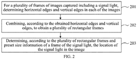
- FIG. 2 is a flow diagram of a method for determining a location of a signal light shown in an exemplary embodiment of the present application.
- the method for determining the location of the signal light shown in an exemplary embodiment of the present application includes: Step 201, for a plurality of frames of images captured including the signal light, determining horizontal edges and vertical edges in each of the images.
- the method provided by the present application can be executed by an electronic device with computing capability, which can receive an image including the signal light captured by an image capturing apparatus.
- the electronic device can also process the received image based on demand, for example, it can implement the solution of identifying a state of the signal light or extracting a light color of the signal light.
- the electronic device when it processes the received image, it can extract the signal light included in the image based on pre-calibrated location information, and then recognize the signal light. If the location of the image capturing apparatus is offset, or a device for setting the signal light is offset, a complete signal light cannot be extracted based on the pre-calibrated location information.
- the electronic device can further determine the location of the signal light in the image according to these images.
- the electronic device can process a plurality of frames of images captured which include the signal light.
- the number of images can be set as n, and the continuous n frames of images captured can be processed.
- the electronic device can also store the determined horizontal edges and vertical edges in a preset list. For example, an edge list can be set in advance, in which the horizontal edge and the vertical edge corresponding to each frame of image can be stored.
- the horizontal edge and the vertical edge can be recorded by means of coordinates.
- an image identification P1 is recorded in the list, and a corresponding horizontal edge [(xl, y), (x2, y)], and a corresponding vertical edge [(x, yl), (x, y2)] of P1 can also be recorded, where x1, x2, y, x, y1, y2 can be pixel coordinate values in the image.
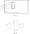
- FIG. 3A is a schematic diagram of an edge detection result shown in an exemplary embodiment of the present application.
- three horizontal edges 32 and two vertical edges 33 can be recognized in one frame of image 31. In other frames of images, horizontal edges and vertical edges can also be recognized.
- the electronic device can use a Sobel operator to determine the horizontal edge and the vertical edge in the image.
- the determined horizontal edge refers to an edge parallel to a frame in a horizontal direction of the signal light in the image
- the vertical edge refers to an edge parallel to a frame in a vertical direction of the signal light in the image.
- the Sobel operator is an important processing method in the field of computer vision. It is mainly used to obtain a first-order gradient of a digital image, and a common application and physical meaning is edge detection.
- the Sobel operator is to weigh gray values of each pixel in four fields of up, down, left, and right of the image, and reach an extreme value at the edge to detect the edge.
- a location of a frame that meets a style of the signal light can be determined in a frame of image by using the Sobel operator for edge recognition.
- step 202 can be executed; otherwise, step 201 is continued to be executed for the received image frames.
- the preset number of frames is n, and when a center of the n frames of images is obtained, step 202 can be executed.
- Step 202 combining, according to the obtained horizontal edges and vertical edges, to obtain a plurality of rectangular frames.
- the electronic device can combine each of the horizontal edges and vertical edges to get a plurality of rectangles.
- the electronic device can combine the horizontal edges and vertical edges recognized in the plurality of images to obtain the plurality of rectangles. For example, in the edge list, two horizontal edges and two vertical edges can be extracted, and the extracted edges can be combined to obtain a rectangle.
- the plurality of rectangles can be obtained by combining the horizontal edges and vertical edges belonging to one frame of image.
- FIG. 3B is a schematic diagram of an edge detection result shown in an exemplary embodiment of the present application.
- the frame of the signal light is a rectangular frame, and four corners of the rectangular frame can be rectangular or arc-shaped. Therefore, the frame of the signal light is included in the rectangles which are obtained by recognizing the edges in the captured image and combining the edges. Therefore, the location of the signal light can be determined according to the rectangular frames obtained in the combination.
- Step 203 determining, according to the plurality of rectangular frames and preset size information of a frame of the signal light, the location of the signal light in the image.
- the rectangular frames can be screened first to get a rectangular frame that meets the frame of the signal light.
- the size information of the frame of the signal light can be set in advance, and the electronic device can acquire the preset size information of the frame of the signal light, and screen the rectangular frames according to the size of the frame of the signal light. For example, a rectangular frame with a size similar to that of the signal light can be taken as a target rectangular frame.
- the electronic device recognizes an edge of the same rectangular frame in different images
- the recognized locations may also be different
- the target rectangular frames are locations of the frame of the signal light determined in different images. Therefore, the location of the signal light in the image can be determined according to these target rectangular frames.
- the location of the signal light in the image can be determined according to screened target rectangular frames. For example, an average location of the target rectangular frames can be calculated as the location of the signal light in the image.
- the present application provides a method for determining a location of a signal light, including: for a plurality of frames of images captured including the signal light, determining horizontal edges and vertical edges in each of the images; combining, according to the obtained horizontal edges and vertical edges, to obtain a plurality of rectangular frames; and determining, according to the plurality of rectangular frames and preset size information of a frame of the signal light, the location of the signal light in the image.
- the location of the signal light can be determined by recognizing an edge in the image, so as to avoid a failure to obtain a complete signal light based on preset labeling information due to change of the location of the image capturing apparatus or the signal light.
- the solution provided by the present application can be realized simply by recognizing the edge in the image, which is less time-consuming and requires less computing power.
- FIG. 4 is a flow diagram of a method for determining a location of a signal light shown in another exemplary embodiment of the present application.
- the method for determining the location of the signal light shown in an exemplary embodiment of the present application includes: Step 401, determining preset designated areas according to a location of a light frame of the signal light.
- the method provided by the present application can be executed by an electronic device with computing capabilities, which can receive an image including the signal light captured by an image capturing apparatus.
- the electronic device can also process the received image based on the demand, for example, it can implement the solution of identifying a state of the signal light or extracting a color of the signal light.
- a location of a light frame of the signal light is labeled in a history image in advance.
- a history image including the signal light can be captured by the image capturing apparatus, and a user can label the light frame of the signal light in the history image. If the locations of the image capturing apparatus and the signal light remain unchanged, then the signal light can be cut out from other images captured by the image capturing apparatus based on the location of the light frame of the signal light.
- the electronic device cannot cut out a complete signal light from the captured images according to the pre-labeled location of the light frame of the signal light.
- the electronic device can determine the preset designated areas in the plurality of frames of images captured including the signal light according to the location of the light frame of the signal light. Specifically, based on the location of the light frame of the signal light, expansion can be done in each of up, down, left and right directions to get the preset designated areas.
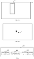
- FIG. 5A is a schematic diagram of determining a preset designated area shown in an exemplary embodiment of the present application.
- a pre-labeled location of a light frame of the signal light 52 can be determined in an image 51, and the electronic device can expand the location of the light frame 52 to obtain a preset designated area 53.
- Step 402 for a plurality of frames of images captured including the signal light, determining horizontal edges and vertical edges in the preset designated area of each of the images.
- the horizontal edges and vertical edges can be determined in the preset designated area of each of the images.
- a size of an image to be processed by the electronic device can be reduced, thereby reducing an amount of data processing of the electronic device. Furthermore, this implementation can further avoid an influence of an edge existing in the area except the signal light in the image on a recognition result.
- a specific method of determining the edge in the preset designated area is similar to step 201 and will not be repeated.
- Edge detection on each of the images can be performed based on a Sobel operator to obtain the horizontal edges and vertical edges in each of the images.
- the Sobel operator is an important processing method in the field of computer vision. It is mainly used to obtain a first-order gradient of a digital image, and a common application and physical meaning is edge detection.
- the Sobel operator is to weigh gray values of each pixel in four fields of up, down, left, and right of the image, and reach an extreme value at the edge to detect the edge.
- a location of a frame that meets a style of the signal light can be determined in a frame of image by using the Sobel operator for edge recognition.
- Step 403 combining the horizontal edges and vertical edges belonging to the same image to obtain the rectangular frames.
- the electronic device can combine the horizontal edges and vertical edges recognized from the same image, so as to determine a possible frame of the signal light in the same image.
- combining the horizontal edges and vertical edges of the same image can reduce the number of rectangular frames obtained by the combination, thus reducing the amount of data processing. Furthermore, four edges of the frame of the signal light will appear in the same image, therefore, a rectangular frame that is consistent with the frame of the signal light can be screened out from the rectangular frames in one frame of image.
- Step 404 acquiring preset size information of the frame of the signal light.
- the size information of the frame of the signal light can be set in advance. For example, a size of the signal light can be written into the electronic device in advance, so that the electronic device can obtain the size information of the frame of the signal light when determining an effective rectangular frame.
- the preset size information of the frame of the signal light can be actual size information of the signal light.
- a location of a light frame of the signal light can be labeled in the history image in advance, and the electronic device can determine the size information of the light frame of the signal light according to the location of the frame of the signal light.
- the electronic device does not need to store the size information of the frame of the signal light, but only needs to determine the size information by using the pre-labeled location of the light frame of the signal light when acquiring the size information of the frame of the signal light, thereby saving storage space.
- Step 405 determining effective rectangular frames in the plurality of rectangular frames according to the preset size information of the frame of the signal light.
- the electronic device can screen the plurality of rectangular frames according to the preset size information of the frame of the signal light to get the effective rectangular frames.
- a rectangular frame whose size conforms to the preset size information of the frame of the signal light can be regarded as an effective rectangular frame in the plurality of rectangular frames.
- a rectangular frame whose length and width are similar to the preset size information of the frame of the signal light is determined as an effective rectangular frame.
- the electronic device can screen out the effective rectangular frame according to an actual size of the signal light, so as to determine accurate location of the signal light according to the effective rectangular frame.
- the preset size information of the frame of the signal light includes any two of following parameters: a height value, a width value and a height width ratio.
- the electronic device can screen out the effective rectangular frame based on these parameters.
- an effective rectangular frame whose size meets any two parameters of the height value, the width value and the height width ratio in the preset size information of the frame of the signal light can be screened out from the plurality of rectangular frames. For example, if there is a rectangular frame whose height conforms to the height value in the parameter, and a height width ratio of the rectangular frame also conforms to the height width ratio in the parameter, then the rectangular frame can be considered as an effective rectangular frame.
- the effective rectangular frame can be obtained by screening using the plurality of parameters, in this way, the effective rectangular frame whose size is consistent with the actual size of the signal light can be screened out.
- Step 406 determining, according to the effective rectangular frames, the location of the signal light in the image.
- the location of the signal light can be determined according to the effective rectangular frames that have been screened out.
- an average location of the effective rectangular frames can be determined as the location of the signal light.
- the electronic device can further screen the effective rectangular frames to get the target rectangular frames.
- the electronic device can determine center points of the effective rectangular frames, and determine the target rectangular frames in the plurality of effective rectangular frames according to the center points. If the locations of the effective rectangular frames all conform to the location of the signal light, then locations of the center points of the effective rectangular frames should also be close. Therefore, the effective rectangular frames can be further screened according to the center points of the effective rectangular frames.
- the electronic device can determine the location of the signal light in the image according to the target rectangular frames. Since the target rectangular frames are preliminarily screened according to the size of the signal light, and then screened again according to the locations of the effective rectangular frames, therefore, the location of the signal light determined according to the target rectangular frames is more accurate.
- the electronic device can process the center points based on a random sample consensus (RANSAC) algorithm to determine target center points.
- RANSAC random sample consensus
- RANSAC can estimate parameters of a mathematical model in an iterative manner from a set of observation data containing "outliers". Outliers are points that do not fit the model.
- the location of the effective rectangular frame conforms to the location of the signal light, the location of the center point of the effective rectangular frame should also be close, which thus meets the mathematical model. Therefore, based on RANSAC, the center points can be filtered to find the target center points which are close to each other.
- RANSAC can select a set of subsets from determined center points and assume that the subsets are inliers.
- Current inliers can be used to estimate a model, and the model is used to test other center points except inliers. If a center point is suitable for the model, it is considered that the center point is also an inlier. If enough center points are classified as assumed inliers, then the estimated model can be considered as accurate, and these center points classified as inliers can be determined as the target center points.
- an effective rectangular frame corresponding to the target center point can be determined as the target rectangular frame. Locations of these target center points are close, so it can be considered that the target rectangular frame is the location of the frame of the signal light recognized by the electronic device in the image.
- FIG. 5B is a schematic diagram of screening a center point shown in an exemplary embodiment of the present application.
- a plurality of center points can be determined according to the determined effective rectangular frames, and the center points can be screened based on the RANSAC algorithm. For example, a center point 54 is not suitable for the estimated model, so the center point 54 can be filtered out, and the remaining center points are the target center points.
- target center points whose locations are gathered together can be filtered out through RANSAC, so as to avoid other effective rectangular frames that are inconsistent with the location of the target rectangular frame, which may affect a determination result of the location of the signal light.
- the electronic device can determine the average location according to the locations of the target rectangular frames, and then get the location of the signal light in the image.
- the target rectangular frames determined in this implementation are rectangular frames which conform to the location of the signal light identified in different frames of images. Therefore, the average location of the determined target rectangular frame is the accurate location of the signal light in the image.
- FIG. 6 is a structural diagram of an apparatus for determining a location of a signal light shown in an exemplary embodiment of the present application.
- an apparatus for determining a location of a signal light 600 includes:
- the apparatus for determining the location of the signal light includes an edge detecting unit, configured to: for a plurality of frames of images captured including the signal light, determine horizontal edges and vertical edges in each of the images; a combining unit, configured to combine, according to the obtained horizontal edges and vertical edges, to obtain a plurality of rectangular frames; and a location determining unit, configured to determine, according to the plurality of rectangular frames and preset size information of a frame of the signal light, the location of the signal light in the image.
- the apparatus provided in the present application can determine the location of the signal light by recognizing an edge in the image, so as to avoid a failure to obtain a complete signal light based on preset labeling information due to change of the location of the image capturing apparatus or the signal light.
- the solution provided by the present application can be realized simply by recognizing the edge in the image, which is less time-consuming and requires less computing power.
- FIG. 7 is a structural diagram of an apparatus for determining a location of a signal light shown in another exemplary embodiment of the present application.
- the apparatus for determining the location of the signal light 600 further includes: a pre-labeling unit 640, configured to label a location of a light frame of the signal light in a history image in advance; where before determining the horizontal edges and the vertical edges in each of the images for the plurality of frames of images captured including the signal light, the edge detecting unit 610 is further configured to:
- the combining unit 620 is specifically configured to: combine the horizontal edge and the vertical edge belonging to a same image to obtain the rectangular frame.
- the location determining unit 630 includes:
- the preset size information of the frame of the signal light includes any two of following parameters: a height value, a width value and a height width ratio; the screening module 632 is specifically configured to: screen out an effective rectangular frame whose size meets any two parameters of the height value, the width value and the height width ratio in the preset size information of the frame of the signal light in the plurality of rectangular frames.
- the location determining module 633 includes:
- the target determining submodule 6331 is specifically configured to:
- the location determining submodule 6332 is specifically configured to: determine an average location of the target rectangular frames to obtain the location of the signal light in the image.
- the edge detecting unit 610 is specifically configured to: perform edge detection on each of the images based on a Sobel operator to obtain the horizontal edges and the vertical edges in each of the images.
- the pre-labeling unit 640 labels a location of a light frame of the signal light in a history image in advance; the acquiring module 631 is specifically configured to: determine the size information of the frame of the signal light according to the location of the light frame of the signal light.
- the present application further provides a computer program product, including a computer program, which is stored in a readable storage medium, at least one processor of an electronic device can read the computer program from the readable storage medium, and at least one processor executes the computer program to cause the electronic device to execute the solution provided in any of the above embodiments.
- the present application further provides a roadside device, including an electronic device as shown below.
- an electronic device and a readable storage medium are further provided.
- FIG. 8 shows a schematic block diagram of an example electronic device 800 that can be used to implement an embodiment of the present application.
- the electronic device is intended to represent various forms of digital computers, such as a laptop computer, a desktop computer, a workstation, a personal digital assistant, a server, a blade server, a mainframe computer, and other suitable computers.
- the electronic device may also represent various forms of mobile apparatuses, such as a personal digital assistant, a cellular phone, a smart phone, a wearable device, and other similar computing apparatuses.
- Components shown herein, connections and relationships thereof, as well as functions thereof are merely examples and are not intended to limit implementations of the present application described and/or claimed herein.
- the electronic device 800 includes a computing unit 801 that may execute various appropriate actions and arrangements according to a computer program stored in read-only memory (ROM) 802 or a computer program loaded into random access memory (RAM) 803 from the storage unit 808.
- ROM read-only memory
- RAM random access memory
- various programs and data needed for the operation of the device 800 can also be stored.
- the computing unit 801, ROM 802 and RAM 803 are connected to each other through a bus 804.
- An input/output (I/O) interface 805 is also connected to the bus 804.
- a plurality of components in the device 800 are connected to the I/O interface 805, including: an input unit 806, such as a keyboard, a mouse, etc.; an output unit 807, such as various types of displays, loudspeakers, and the like; a storage unit 808, such as a magnetic disk, an optical disk, etc.; and a communicating unit 809, such as a network card, a modem, a wireless communication transceiver, and the like.
- the communicating unit 809 allows the device 800 to exchange information/data with other devices through a computer network such as Internet and/or various telecommunication networks.
- the computing unit 801 may be a variety of general and/or special processing components with processing and computing capabilities. Some examples of the computing unit 801 include but are not limited to a central processing unit (CPU), a graphics processing unit (GPU), various dedicated artificial intelligence (AI) computing chips, various computing units running machine learning model algorithms, a digital signal processor (DSP), and any appropriate processor, controller, microcontroller, etc.
- the computing unit 801 performs various methods and processes described above, such as the method for determining the location of the signal light.
- the method for determining the location of the signal light may be implemented as a computer software program that is tangibly contained in a machine-readable medium, such as a storage unit 808.
- some or all of the computer programs may be loaded and/or installed on device 800 via ROM 802 and/or communicating unit 809.
- the computer program When the computer program is loaded into the RAM 803 and executed by the computing unit 801, one or more steps of the method for determining the location of the signal light described above may be executed.
- the computing unit 801 may be configured to perform the method for determining the location of the signal light by any other appropriate means (e.g., by means of firmware).
- Various implementations of the systems and technologies described above herein can be implemented in a digital electronic circuit system, an integrated circuit system, a field programmable gate array (FPGA), an application specific integrated circuit (ASIC), an application specific standard product (ASSP), a system on chip (SOC), a complex programmable logic device (CPLD), computer hardware, firmware, software, and/or a combination thereof.
- FPGA field programmable gate array
- ASIC application specific integrated circuit
- ASSP application specific standard product
- SOC system on chip
- CPLD complex programmable logic device
- These various embodiments may include: being implemented in one or more computer programs, the one or more computer programs may be executed and/or interpreted on a programmable system including at least one programmable processor, the programmable processor may be a dedicated or general programmable processor, and can receive data and instructions from a storage system, at least one input apparatus, and at least one output apparatus, and transmitting the data and instructions to the storage system, the at least one input apparatus, and the at least one output apparatus.
- Program codes for implementing the method of the present disclosure may be written in any combination of one or more programming languages. These program codes may be provided to a processor or controller of a general computer, a dedicated computer, or other programmable data processing apparatus, so that when the program codes are executed by the processor or controller, the functions/operations specified in the flowchart and/or block diagram are implemented.
- the program codes can be executed entirely on a machine, partly executed on the machine, partly executed on the machine and partly executed on a remote machine as an independent software package, or entirely on the remote machine or server.
- a machine-readable medium may be a tangible medium that may contain or store programs for use by or in combination with an instruction execution system, apparatus or device.
- the machine-readable medium may be a machine-readable signal medium or a machine-readable storage medium.
- Machine-readable media may include, but are not limited to, electronic, magnetic, optical, electromagnetic, infrared, or semiconductor systems, apparatuses, or devices, or any suitable combination of the foregoing.
- machine-readable storage media may include one or more line based electrical connection, a portable computer disk, a hard disk, a random access memory (RAM), a read-only memory (ROM), an erasable programmable read-only memory (EPROM or flash memory), an optical fiber, a compact disk read-only memory (CD-ROM), an optical storage device, a magnetic storage device, or any suitable combination of the above.
- RAM random access memory
- ROM read-only memory
- EPROM or flash memory erasable programmable read-only memory
- CD-ROM compact disk read-only memory
- magnetic storage device or any suitable combination of the above.
- the systems and technologies described herein may be implemented on a computer, where the computer has: a display apparatus (e.g., a CRT (cathode ray tube) or LCD (liquid crystal display) monitor) for displaying information to the user; and a keyboard and a pointing apparatus (e.g., a mouse or a trackball), through which the user can provide inputs to the computer.
- a display apparatus e.g., a CRT (cathode ray tube) or LCD (liquid crystal display) monitor
- a keyboard and a pointing apparatus e.g., a mouse or a trackball
- Other types of apparatuses may also be used to provide interaction with the user; for example, the feedback provided to the user may be any form of sensing feedback (for example, visual feedback, auditory feedback, or tactile feedback); and the input from the user may be received in any form (including acoustic input, voice input, tactile input).
- the systems and technologies described here may be implemented in a computing system (e.g., a data server) including a back-end component, or in a computing system (e.g., an application server) including a middleware component, or in a computing system (e.g., a user computer having a graphical user interface or a web browser, through which the user can interact with the implementations of the systems and technologies described herein) including a front-end component, or in a computing system including any combination of the back-end component, the middleware component, or the front-end component.
- the components of the system may be interconnected via digital data communication (e.g., a communication network) in any form or medium. Examples of the communication network include: a local area network (LAN), a wide area network (WAN) and Internet.
- a computer system may include a client and a server.
- the client and the server are generally located far away from each other and usually interact with each other through a communication network.
- a relationship between the client and the server is generated by computer programs running on corresponding computers and having a client-server relationship between each other.
- the server can be a cloud server, also known as a cloud computing server or a cloud host. It is a host product in a cloud computing service system, which solves shortcomings of traditional physical host and VPS services ("Virtual Private Server", or "VPS") such as difficult management and weak business scalability.
- the server can also be a distributed system server or a server combined with blockchain.
- steps can be reordered, added, or deleted by using the various forms of processes shown above.
- steps recited in the present application can be performed in parallel, in sequence or in different orders, as long as expected results of the technical solutions disclosed by the present application can be realized, and there is no limitation herein.
Landscapes
- Engineering & Computer Science (AREA)
- Physics & Mathematics (AREA)
- General Physics & Mathematics (AREA)
- Theoretical Computer Science (AREA)
- Computer Vision & Pattern Recognition (AREA)
- Multimedia (AREA)
- Geometry (AREA)
- Quality & Reliability (AREA)
- Image Analysis (AREA)
- Traffic Control Systems (AREA)
- Image Processing (AREA)
Applications Claiming Priority (1)
| Application Number | Priority Date | Filing Date | Title |
|---|---|---|---|
| CN202011588838.9A CN112700410A (zh) | 2020-12-28 | 2020-12-28 | 信号灯位置确定方法、装置、存储介质、程序、路侧设备 |
Publications (2)
| Publication Number | Publication Date |
|---|---|
| EP3872701A2 true EP3872701A2 (de) | 2021-09-01 |
| EP3872701A3 EP3872701A3 (de) | 2022-01-12 |
Family
ID=75513056
Family Applications (1)
| Application Number | Title | Priority Date | Filing Date |
|---|---|---|---|
| EP21183669.7A Withdrawn EP3872701A3 (de) | 2020-12-28 | 2021-07-05 | Verfahren und vorrichtung zur bestimmung des orts von signallicht, speichermedium, programm und strassenseitige vorrichtung |
Country Status (5)
| Country | Link |
|---|---|
| US (1) | US11810320B2 (de) |
| EP (1) | EP3872701A3 (de) |
| JP (1) | JP7295213B2 (de) |
| KR (1) | KR20210102123A (de) |
| CN (1) | CN112700410A (de) |
Families Citing this family (6)
| Publication number | Priority date | Publication date | Assignee | Title |
|---|---|---|---|---|
| CN113221878A (zh) * | 2021-04-26 | 2021-08-06 | 阿波罗智联(北京)科技有限公司 | 应用于信号灯检测的检测框调整方法、装置及路侧设备 |
| CN113408409A (zh) * | 2021-06-17 | 2021-09-17 | 阿波罗智联(北京)科技有限公司 | 交通信号灯识别方法、设备、云控平台和车路协同系统 |
| CN114581873B (zh) * | 2022-03-11 | 2023-08-18 | 阿波罗智联(北京)科技有限公司 | 筛选路侧设备的方法、装置、设备、介质及产品 |
| CN115973163A (zh) * | 2023-01-19 | 2023-04-18 | 国汽智控(北京)科技有限公司 | 基于信号灯的车辆控制方法、装置、电子设备及存储介质 |
| CN116453092A (zh) * | 2023-04-27 | 2023-07-18 | 广州小鹏自动驾驶科技有限公司 | 信号灯关联方法、装置、设备及存储介质 |
| CN116468868B (zh) * | 2023-04-27 | 2024-08-09 | 广州小鹏自动驾驶科技有限公司 | 交通信号灯的建图方法、装置、设备及存储介质 |
Family Cites Families (11)
| Publication number | Priority date | Publication date | Assignee | Title |
|---|---|---|---|---|
| WO2010115020A2 (en) | 2009-04-01 | 2010-10-07 | Robert Daniel Mcathur | Color and pattern detection system |
| CN103679733B (zh) * | 2013-12-18 | 2018-06-05 | 浙江宇视科技有限公司 | 一种信号灯图像处理方法及其装置 |
| JP6455596B2 (ja) * | 2015-07-08 | 2019-01-23 | 日産自動車株式会社 | 灯火器検出装置及び灯火器検出方法 |
| KR101877809B1 (ko) * | 2017-02-21 | 2018-07-12 | 연세대학교 산학협력단 | Gpu를 이용한 신호등 인식 장치 및 방법 |
| CN107730481B (zh) * | 2017-09-19 | 2020-09-29 | 浙江大华技术股份有限公司 | 一种交通信号灯图像处理方法及交通信号灯图像处理装置 |
| JP2019053619A (ja) * | 2017-09-15 | 2019-04-04 | 株式会社東芝 | 信号識別装置、信号識別方法、及び運転支援システム |
| CN109035198A (zh) * | 2018-06-07 | 2018-12-18 | 华南理工大学 | 基于边缘检测的室外可见光通信的led检测方法 |
| JP7195135B2 (ja) * | 2018-12-21 | 2022-12-23 | キヤノン株式会社 | 画像処理装置、画像処理装置が行う制御方法およびプログラム |
| CN111639656A (zh) * | 2020-05-28 | 2020-09-08 | 东软睿驰汽车技术(沈阳)有限公司 | 交通信号灯识别方法及装置 |
| CN112101223B (zh) * | 2020-09-16 | 2024-04-12 | 阿波罗智联(北京)科技有限公司 | 检测方法、装置、设备和计算机存储介质 |
| CN111931726B (zh) * | 2020-09-23 | 2024-06-11 | 阿波罗智联(北京)科技有限公司 | 交通灯检测的方法、装置、计算机存储介质和路侧设备 |
-
2020
- 2020-12-28 CN CN202011588838.9A patent/CN112700410A/zh active Pending
-
2021
- 2021-07-02 US US17/366,604 patent/US11810320B2/en active Active
- 2021-07-05 EP EP21183669.7A patent/EP3872701A3/de not_active Withdrawn
- 2021-07-09 KR KR1020210090202A patent/KR20210102123A/ko not_active Withdrawn
- 2021-12-24 JP JP2021210160A patent/JP7295213B2/ja active Active
Also Published As
| Publication number | Publication date |
|---|---|
| US20210334980A1 (en) | 2021-10-28 |
| EP3872701A3 (de) | 2022-01-12 |
| CN112700410A (zh) | 2021-04-23 |
| JP2022043214A (ja) | 2022-03-15 |
| JP7295213B2 (ja) | 2023-06-20 |
| KR20210102123A (ko) | 2021-08-19 |
| US11810320B2 (en) | 2023-11-07 |
Similar Documents
| Publication | Publication Date | Title |
|---|---|---|
| US11810320B2 (en) | Method and apparatus for determining location of signal light, storage medium, program and roadside device | |
| CN112560862B (zh) | 文本识别方法、装置及电子设备 | |
| CN113011323B (zh) | 通行状态的获取方法、相关装置、路侧设备及云控平台 | |
| CN109726661B (zh) | 图像处理方法及装置、介质和计算设备 | |
| EP4080479A2 (de) | Verfahren zur identifizierung von verkehrsampeln, vorrichtung, cloud-steuerungsplattform und fahrzeug-strasse-koordinationssystem | |
| JP7258101B2 (ja) | 画像の手ぶれ補正方法、装置、電子機器、記憶媒体、コンピュータプログラム製品、路側機およびクラウド制御プラットフォーム | |
| CN113362227B (zh) | 图像处理方法、装置、电子设备及存储介质 | |
| EP3872702A2 (de) | Lichtfarbe-identifizierungsverfahren und vorrichtung für signalleuchte und strassenseitige geräte | |
| CN113378958A (zh) | 自动标注方法、装置、设备、存储介质及计算机程序产品 | |
| CN113378836A (zh) | 图像识别方法、装置、设备、介质及程序产品 | |
| CN113591580A (zh) | 图像标注方法、装置、电子设备和存储介质 | |
| CN114565908A (zh) | 车道线的检测方法、装置、电子设备及存储介质 | |
| KR20220151583A (ko) | 영상 처리 방법, 장치, 전자 기기, 저장 매체 및 컴퓨터 프로그램 | |
| CN114333409B (zh) | 目标跟踪方法、装置、电子设备及存储介质 | |
| CN112700657B (zh) | 用于生成检测信息的方法、装置、路侧设备和云控平台 | |
| CN112863187B (zh) | 感知模型的检测方法、电子设备、路侧设备和云控平台 | |
| CN115048283A (zh) | 页面测试方法、装置、设备、存储介质及程序 | |
| CN113126120A (zh) | 数据标注方法、装置、设备、存储介质以及计算机程序产品 | |
| CN113628239A (zh) | 显示优化方法、相关装置及计算机程序产品 | |
| CN112988932B (zh) | 高精地图标注方法、装置、设备、可读存储介质及产品 | |
| CN114926484A (zh) | 点云数据的标注方法、装置、设备以及存储介质 | |
| CN114330543A (zh) | 模型训练方法、装置、设备、介质及程序产品 | |
| CN114519739A (zh) | 一种基于识别装置的方向定位方法、装置及存储介质 | |
| CN113554882A (zh) | 用于输出信息的方法、装置、设备以及存储介质 | |
| CN113887331A (zh) | 图像处理方法、事件检测方法、装置、设备和存储介质 |
Legal Events
| Date | Code | Title | Description |
|---|---|---|---|
| PUAI | Public reference made under article 153(3) epc to a published international application that has entered the european phase |
Free format text: ORIGINAL CODE: 0009012 |
|
| STAA | Information on the status of an ep patent application or granted ep patent |
Free format text: STATUS: REQUEST FOR EXAMINATION WAS MADE |
|
| 17P | Request for examination filed |
Effective date: 20210705 |
|
| AK | Designated contracting states |
Kind code of ref document: A2 Designated state(s): AL AT BE BG CH CY CZ DE DK EE ES FI FR GB GR HR HU IE IS IT LI LT LU LV MC MK MT NL NO PL PT RO RS SE SI SK SM TR |
|
| PUAL | Search report despatched |
Free format text: ORIGINAL CODE: 0009013 |
|
| AK | Designated contracting states |
Kind code of ref document: A3 Designated state(s): AL AT BE BG CH CY CZ DE DK EE ES FI FR GB GR HR HU IE IS IT LI LT LU LV MC MK MT NL NO PL PT RO RS SE SI SK SM TR |
|
| RIC1 | Information provided on ipc code assigned before grant |
Ipc: G06T 7/73 20170101ALI20211207BHEP Ipc: G06K 9/46 20060101ALI20211207BHEP Ipc: G06K 9/32 20060101ALI20211207BHEP Ipc: G06K 9/00 20060101AFI20211207BHEP |
|
| STAA | Information on the status of an ep patent application or granted ep patent |
Free format text: STATUS: EXAMINATION IS IN PROGRESS |
|
| 17Q | First examination report despatched |
Effective date: 20221128 |
|
| STAA | Information on the status of an ep patent application or granted ep patent |
Free format text: STATUS: THE APPLICATION HAS BEEN WITHDRAWN |
|
| 18W | Application withdrawn |
Effective date: 20230329 |