EP3872381A1 - Tube and treatment device - Google Patents
Tube and treatment device Download PDFInfo
- Publication number
- EP3872381A1 EP3872381A1 EP19876333.6A EP19876333A EP3872381A1 EP 3872381 A1 EP3872381 A1 EP 3872381A1 EP 19876333 A EP19876333 A EP 19876333A EP 3872381 A1 EP3872381 A1 EP 3872381A1
- Authority
- EP
- European Patent Office
- Prior art keywords
- tube
- portions
- peripheral surface
- thick
- walled
- Prior art date
- Legal status (The legal status is an assumption and is not a legal conclusion. Google has not performed a legal analysis and makes no representation as to the accuracy of the status listed.)
- Withdrawn
Links
- 230000002093 peripheral effect Effects 0.000 claims abstract description 56
- 239000012530 fluid Substances 0.000 claims description 14
- 238000000034 method Methods 0.000 claims description 8
- 239000007788 liquid Substances 0.000 description 25
- 238000004519 manufacturing process Methods 0.000 description 20
- 239000004065 semiconductor Substances 0.000 description 12
- 238000012986 modification Methods 0.000 description 11
- 230000004048 modification Effects 0.000 description 11
- 239000000463 material Substances 0.000 description 10
- 235000012431 wafers Nutrition 0.000 description 7
- 239000007789 gas Substances 0.000 description 6
- 239000000126 substance Substances 0.000 description 5
- 239000000758 substrate Substances 0.000 description 5
- XLYOFNOQVPJJNP-UHFFFAOYSA-N water Chemical compound O XLYOFNOQVPJJNP-UHFFFAOYSA-N 0.000 description 5
- 238000005452 bending Methods 0.000 description 4
- IJGRMHOSHXDMSA-UHFFFAOYSA-N Atomic nitrogen Chemical compound N#N IJGRMHOSHXDMSA-UHFFFAOYSA-N 0.000 description 3
- 239000008367 deionised water Substances 0.000 description 3
- 229910021641 deionized water Inorganic materials 0.000 description 3
- 229910001873 dinitrogen Inorganic materials 0.000 description 3
- 229920001971 elastomer Polymers 0.000 description 3
- 229920000915 polyvinyl chloride Polymers 0.000 description 3
- 239000004800 polyvinyl chloride Substances 0.000 description 3
- 229920005989 resin Polymers 0.000 description 3
- 239000011347 resin Substances 0.000 description 3
- 230000000717 retained effect Effects 0.000 description 3
- 238000004140 cleaning Methods 0.000 description 2
- 238000005260 corrosion Methods 0.000 description 2
- 230000007797 corrosion Effects 0.000 description 2
- 238000001035 drying Methods 0.000 description 2
- 235000013305 food Nutrition 0.000 description 2
- 239000004973 liquid crystal related substance Substances 0.000 description 2
- 229940127554 medical product Drugs 0.000 description 2
- 239000000825 pharmaceutical preparation Substances 0.000 description 2
- 229940127557 pharmaceutical product Drugs 0.000 description 2
- 229920002397 thermoplastic olefin Polymers 0.000 description 2
- JOYRKODLDBILNP-UHFFFAOYSA-N Ethyl urethane Chemical compound CCOC(N)=O JOYRKODLDBILNP-UHFFFAOYSA-N 0.000 description 1
- 244000043261 Hevea brasiliensis Species 0.000 description 1
- HBBGRARXTFLTSG-UHFFFAOYSA-N Lithium ion Chemical compound [Li+] HBBGRARXTFLTSG-UHFFFAOYSA-N 0.000 description 1
- 239000004698 Polyethylene Substances 0.000 description 1
- 239000000853 adhesive Substances 0.000 description 1
- 230000001070 adhesive effect Effects 0.000 description 1
- 230000000694 effects Effects 0.000 description 1
- 239000000806 elastomer Substances 0.000 description 1
- 239000000446 fuel Substances 0.000 description 1
- 229910001416 lithium ion Inorganic materials 0.000 description 1
- 230000014759 maintenance of location Effects 0.000 description 1
- 229920003052 natural elastomer Polymers 0.000 description 1
- 229920001194 natural rubber Polymers 0.000 description 1
- -1 polyethylene Polymers 0.000 description 1
- 229920000573 polyethylene Polymers 0.000 description 1
- 239000002994 raw material Substances 0.000 description 1
- 230000002787 reinforcement Effects 0.000 description 1
- 230000000452 restraining effect Effects 0.000 description 1
- 229920002379 silicone rubber Polymers 0.000 description 1
- 239000004945 silicone rubber Substances 0.000 description 1
- 238000004088 simulation Methods 0.000 description 1
Images




Classifications
-
- F—MECHANICAL ENGINEERING; LIGHTING; HEATING; WEAPONS; BLASTING
- F16—ENGINEERING ELEMENTS AND UNITS; GENERAL MEASURES FOR PRODUCING AND MAINTAINING EFFECTIVE FUNCTIONING OF MACHINES OR INSTALLATIONS; THERMAL INSULATION IN GENERAL
- F16L—PIPES; JOINTS OR FITTINGS FOR PIPES; SUPPORTS FOR PIPES, CABLES OR PROTECTIVE TUBING; MEANS FOR THERMAL INSULATION IN GENERAL
- F16L11/00—Hoses, i.e. flexible pipes
- F16L11/04—Hoses, i.e. flexible pipes made of rubber or flexible plastics
- F16L11/12—Hoses, i.e. flexible pipes made of rubber or flexible plastics with arrangements for particular purposes, e.g. specially profiled, with protecting layer, heated, electrically conducting
- F16L11/121—Hoses, i.e. flexible pipes made of rubber or flexible plastics with arrangements for particular purposes, e.g. specially profiled, with protecting layer, heated, electrically conducting specially profiled cross sections
-
- F—MECHANICAL ENGINEERING; LIGHTING; HEATING; WEAPONS; BLASTING
- F16—ENGINEERING ELEMENTS AND UNITS; GENERAL MEASURES FOR PRODUCING AND MAINTAINING EFFECTIVE FUNCTIONING OF MACHINES OR INSTALLATIONS; THERMAL INSULATION IN GENERAL
- F16L—PIPES; JOINTS OR FITTINGS FOR PIPES; SUPPORTS FOR PIPES, CABLES OR PROTECTIVE TUBING; MEANS FOR THERMAL INSULATION IN GENERAL
- F16L57/00—Protection of pipes or objects of similar shape against external or internal damage or wear
- F16L57/02—Protection of pipes or objects of similar shape against external or internal damage or wear against cracking or buckling
Definitions
- the present invention relates to a flexible tube and a processing apparatus including the tube.
- tubes are used for the flow of various chemical liquids, deionized water, or gases such as nitrogen gas in manufacturing apparatuses for precision electronic components such as semiconductor wafers, flat panel displays (e.g., liquid crystal displays and organic EL displays), and chemical batteries (e.g., lithium-ion batteries and fuel cells).
- a large number of tubes are used for the flow of ink in inkjet printers for commercial printing.
- a large number of tubes are used for the flow of raw materials in manufacturing apparatuses for medical and pharmaceutical products and in manufacturing apparatuses for food products.
- tubes for the flow of liquids or gases are sometimes used in other fields such as the fields of medical devices and architecture.
- tubes pliantly flex and deform for convenience of routing or arrangement. For this reason, a large number of tubes are made of rubber or flexible resins. Conventional tubes are disclosed in Patent Literatures 1 and 2, for example.
- a tube is cylindrical in shape as disclosed in Patent Literatures 1 and 2, the tube is crushed to block the internal flow passage thereof in some cases when an external pressure is applied to the tube or when the tube is bent locally at a steep angle.
- Fig. 9 is a photograph showing a bent location of a conventional cylindrical tube when the tube is bent.
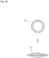
- Fig. 10 is a view showing cross sections of a bent location of a conventional cylindrical tube T when the tube T is bent.
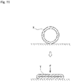
- Fig. 11 is a view showing cross sections of the conventional cylindrical tube T when the tube T is placed on a flat surface and pressure F is applied thereto from above.
- opposed portions of the inner peripheral surface of the conventional cylindrical tube T are prone to come close to each other when the tube T is deformed. The internal flow passage of the tube T is thus prone to be blocked.
- a first aspect of the present invention is intended for a flexible tube comprising: a tubular outer peripheral surface; and a tubular inner peripheral surface, the outer peripheral surface including at least one corner portion protruding outwardly, the inner peripheral surface including a first arcuate portion positioned inside the corner portion and having a radius of curvature greater than that of the corner portion.
- a second aspect of the present invention is intended for the tube of the first aspect, which further comprises a plurality of thick-walled portions arranged in a circumferential direction, each of the thick-walled portions including the corner portion and the first arcuate portion.
- a third aspect of the present invention is intended for the tube of the second aspect, which further comprises a thin-walled portion having a thickness less than that of the thick-walled portions and provided between adjacent ones of the thick-walled portions.
- a fourth aspect of the present invention is intended for the tube of the third aspect, wherein the thick-walled portions are odd in number.
- a fifth aspect of the present invention is intended for the tube of the fourth aspect, wherein the at least one corner portion includes three corner portions, wherein the outer peripheral surface includes the three corner portions and planar side portions each positioned between adjacent ones of the corner portions, and wherein the inner peripheral surface is in a cylindrical shape including the first arcuate portion.
- a sixth aspect of the present invention is intended for the tube of any one of the first to fifth aspects, wherein the inner peripheral surface forms a flow passage.
- a seventh aspect of the present invention is intended for the tube of any one of the first to fifth aspects, the tube being mounted on an outer peripheral surface of another tube.
- An eighth aspect of the present invention is intended for a processing apparatus comprising: a processing part for performing a process using a fluid on an object, and a tube as recited in any one of the first to seventh aspects, wherein the tube is used to perform at least one of the supply of the fluid to the processing part and the drainage of the fluid from the processing part.
- opposed portions of the inner peripheral surface of the tube are less prone to be close to each other when an external force is applied to the tube or when the tube is locally bent. This restrains the flow passage in the tube from being blocked.
- the flow passage in the tube is restrained from being blocked regardless of the direction of the external pressure and the direction of bending.
- the deformation of the tube is concentrated on the thin-walled portion. This further restrains the flow passage in the tube from being blocked.
- each of the thick-walled portions and the thin-walled portion face each other across the internal flow passage. This further restrains the flow passage in the tube from being blocked.
- Fig. 1 is a perspective view of a tube 1 according to one embodiment of the present invention.
- This tube 1 is a tube having a flow passage 2 for passing fluid (liquid or gas) therein.
- the tube 1 is flexible. This allows the tube 1 to be disposed in a location while being pliantly curved in accordance with the shape of the location where the tube 1 is to be placed. Rubber or flexible resins are used as the material of the tube 1. Specific examples of the material of the tube 1 used herein include silicone rubber, natural rubber, urethane gel, flexible polyvinyl chloride, elastomer resin, PVC (polyvinyl chloride), TPO (olefinic thermoplastic elastomer), polyethylene, and fluororesin. The material of the tube 1 may be selected, as appropriate, depending on application purposes.
- the tube 1 may be made of a plurality of materials.
- the tube 1 may have a multi-layer structure including an inner-layer tube made of a material and an outer-layer tube made of another material.
- Fig. 2 is a sectional view of the tube 1 taken along a plane perpendicular to the direction of the flow passage thereof. As shown in Figs. 1 and 2 , the tube 1 has an outer peripheral surface 10 substantially in the shape of a triangular prism and an inner peripheral surface 20 in a cylindrical shape.
- the outer peripheral surface 10 in a cross section of the tube 1 in the present embodiment is substantially in the shape of an equilateral triangle. More specifically, the outer peripheral surface 10 of the tube 1 has three corner portions 11 and three side portions 12. The three corner portions 11 protrude outwardly of the tube 1 and extend continuously in the direction of the flow passage. The three corner portions 11 are arranged in circumferentially equally spaced relation around the flow passage 2. Each of the three side portions 12 is positioned between adjacent ones of the corner portions 11. As shown in Figs. 1 and 2 , each of the side portions 12 spreads in a planar shape and extends continuously in the direction of the flow passage.
- the inner peripheral surface 20 of the tube 1 in the present embodiment is in a cylindrical shape. That is, the inner peripheral surface 20 in a cross section of the tube 1 is circular in shape, as shown in Fig. 2 .
- the radius of curvature of the inner peripheral surface 20 is greater than that of the aforementioned corner portions 11.
- Arcuate portions of the inner peripheral surface 20 of the tube 1 which are positioned inside the respective corner portions 11 are referred to hereinafter as "first arcuate portions 21".
- Arcuate portions of the inner peripheral surface 20 of the tube 1 which are positioned inside the respective side portions 12 are referred to hereinafter as "second arcuate portions 22".
- the tube 1 has three thick-walled portions 30 and three thin-walled portions 40 thinner than the thick-walled portions 30.
- Each of the thick-walled portions 30 has one of the corner portions 11 and one of the first arcuate portions 21.
- Each of the thin-walled portions 40 has one of the side portions 12 and one of the second arcuate portions 22.
- the three thick-walled portions 30 are arranged in circumferentially equally spaced relation around the flow passage 2.
- Each of the thin-walled portions 40 is positioned between adjacent ones of the thick-walled portions 30. That is, the thick-walled portions 30 and the thin-walled portions 40 are circumferentially alternately arranged around the flow passage 2.
- the inner peripheral surface 20 of the tube 1 shall have a diameter of not less than 2 mm, for example.
- the tube 1 shall have a length of 100 mm to 100 m, for example. It should be noted that the inner diameter and length of the tube in the present invention are not limited to these numerical ranges.
- Fig. 3 is a photograph showing a bent location of a tube having the same shape as that of the present embodiment when the tube is bent.
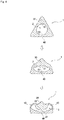
- Fig. 4 is a sectional view showing cross sections of a bent location when the tube 1 of the present embodiment is bent. As shown in Fig. 4 , when the tube 1 is bent, one of the thick-walled portions 30 of the tube 1 and the thin-walled portion 40 opposed to the one thick-walled portion 30 are displaced toward each other. In the tube 1 of the present embodiment, however, the shape of the first arcuate portions 21 is retained because the shape of the thick-walled portions 30 is less prone to change than that of the thin-walled portions 40.
- the flow passage 2 is ensured between one of the first arcuate portions 21 and the second arcuate portion 22 opposed to the one first arcuate portion 21, as shown in the middle part of Fig. 4 .
- the first arcuate portion 21 and the second arcuate portion 22 opposed to the first arcuate portion 21 are less prone to be close to each other. This restrains the flow passage 2 in the tube 1 from being blocked.
- the deformation of the thick-walled portion 30 becomes larger, so that the shape of the first arcuate portion 21 is changed in some cases, as shown in the lower part of Fig. 4 .
- the pair of thin-walled portions 40 positioned on opposite sides of the thick-walled portion 30 bulge outwardly of the tube 1.
- the flow passage 2 is ensured inside the pair of thin-walled portions 40. This also restrains the flow passage 2 in the tube 1 from being blocked.
- the thick-walled portions 30 are arranged in circumferentially equally spaced relation in the tube 1 of the present embodiment. This achieves the state shown in the middle or lower part of Fig. 4 regardless of the direction of bending of the tube 1. Therefore, the flow passage 2 in the tube 1 is restrained from being blocked regardless of the direction of bending of the tube 1.
- the tube 1 of the present embodiment includes the thin-walled portions 40 each positioned between adjacent ones of the thick-walled portions 30.
- the deformation of the tube 1 is concentrated on the thin-walled portions 40 when the tube 1 is locally bent. This further restrains the shape of the first arcuate portions 21 of the thick-walled portions 30 from changing to accordingly further restrain the flow passage 2 in the tube 1 from being blocked.
- Fig. 5 is a view (simulation result) showing the deformation of the tube 1 when pressure F similar to that of Fig. 11 is externally applied to the tube 1 of the present embodiment.
- the shape of the first arcuate portions 21 is also retained because the shape of the thick-walled portions 30 is less prone to change than that of the thin-walled portions 40. For this reason, the flow passage 2 is ensured between one of the first arcuate portions 21 and the second arcuate portion 22 opposed to the one first arcuate portion 21, as shown in the middle and lower parts of Fig. 5 . In other words, the first arcuate portion 21 and the second arcuate portion 22 opposed to the first arcuate portion 21 are less prone to be close to each other. This restrains the flow passage 2 in the tube 1 from being blocked.
- the thick-walled portions 30 are arranged in circumferentially equally spaced relation in the tube 1 of the present embodiment. This achieves the state shown in the middle or lower part of Fig. 5 regardless of the direction of the external pressure F. Therefore, the flow passage 2 in the tube 1 is restrained from being blocked regardless of the direction of the external pressure F.
- the tube 1 of the present embodiment includes the thin-walled portions 40 each positioned between adjacent ones of the thick-walled portions 30.
- the deformation of the tube 1 is concentrated on the thin-walled portions 40 when the tube 1 receives the external pressure F. This further restrains the shape of the first arcuate portions 21 of the thick-walled portions 30 from changing to accordingly further restrain the flow passage 2 in the tube 1 from being blocked.
- Fig. 6 is a conceptual view of a processing apparatus 100 including the aforementioned tube 1.
- this processing apparatus 100 includes a processing part 110 for performing a process using a fluid on an object 9.
- the processing apparatus 100 further includes at least one of a supply tube 1A for supplying a fluid to the processing part 110 and a drain tube 1B for draining a fluid from the processing part 110.
- the aforementioned tube 1 having the outer peripheral surface 10 substantially in the shape of a triangular prism is used for the supply tube 1A and the drain tube 1B.
- the processing part 110 has a nozzle attached to a tip of the supply tube 1A.
- the processing part 110 ejects a processing liquid that is a fluid supplied thereto through the supply tube 1A from the nozzle toward a surface of the semiconductor wafer.
- the processing liquid include various chemical liquids such as a resist solution, a developing solution and a cleaning solution, and deionized water. After use, the processing liquid is drained from the processing part 110 through the drain tube 1B to the outside.
- Materials resistant to corrosion by the aforementioned processing liquid and flexible are used as the materials of the supply tube 1A and the drain tube 1B.
- supply tube 1A and the drain tube 1B may be tubes for passing gases for use in processing the semiconductor wafers (e.g., nitrogen gas for use in a drying process).
- the processing apparatus 100 is a manufacturing apparatus for displays such as liquid crystal display devices and organic EL display devices.
- the object 9 is a substrate for a display.
- the processing part 110 has a nozzle attached to a tip of the supply tube 1A.
- the processing part 110 ejects a processing liquid that is a fluid supplied thereto through the supply tube 1A from the nozzle toward a surface of the substrate.
- the processing liquid include various chemical liquids such as a resist solution, a developing solution and a cleaning solution, and deionized water. After use, the processing liquid is drained from the processing part 110 through the drain tube 1B to the outside.
- Materials resistant to corrosion by the aforementioned processing liquid and flexible are used as the materials of the supply tube 1A and the drain tube 1B.
- Processing liquids having an extremely high viscosity are used in manufacturing apparatuses for flexible displays which have been under development in recent years. In that case, even a small external pressure or slight bending is prone to block the flow of the processing liquid in the tube.
- the use of the tube 1 of this shape for the supply tube 1A and the drain tube 1B of the apparatus restrains the retention of the processing liquid. This allows the ejection of the processing liquid having a high viscosity from the nozzle with stability.
- supply tube 1A and the drain tube 1B may be tubes for passing gases for use in manufacturing the displays (e.g., nitrogen gas for use in a drying process).
- the processing part 110 has a print head attached to a tip of the supply tube 1A.
- the processing part 110 ejects ink that is a fluid supplied thereto through the supply tube 1A in the form of droplets from the head. This causes an image to be printed on a surface of the printing paper.
- Inkjet printers use fine droplets of ink ejected from the head to print high-definition images. For this reason, the stagnation of the supply of ink to the processing part 110 exerts significant influence on the quality of printed images. In particular, the printing speed of inkjet printers has become increasingly faster in recent years. Once the supply of ink stagnates, a large amount of printing paper is transported during the stagnation, which in turn results in a large loss. In such an inkjet printer, the use of the tube 1 of this shape for the supply tube 1A and the drain tube 1B allows the stable supply of ink. This allows the printing process to be performed at high speeds and with stability.
- the processing apparatus 100 may be an apparatus other than the semiconductor manufacturing apparatus, the display manufacturing apparatus, and the inkjet printer which are described above.
- the processing apparatus 100 may be a manufacturing apparatus for chemical batteries, a manufacturing apparatus for medical and pharmaceutical products, a manufacturing apparatus for food products, or a medical device used to treat living organisms.
- the tube 1 of this shape may be used for water supply pipes, water distributing pipes, gas piping, and the like which are incidental facilities of buildings.
- Fig. 7 is a sectional view of the tube 1 according to a first modification taken along a plane perpendicular to the direction of the flow passage thereof.
- the outer peripheral surface 10 in a cross section of the tube 1 is substantially in the shape of an equilateral pentagon. More specifically, the outer peripheral surface 10 of the tube 1 has five corner portions 11 and five side portions 12. The five corner portions 11 protrude outwardly of the tube 1 and extend continuously in the direction of the flow passage. The five corner portions 11 are arranged in circumferentially equally spaced relation around the flow passage 2.
- Each of the five side portions 12 is positioned between adjacent ones of the corner portions 11.
- Each of the side portions 12 spreads in a planar shape and extends continuously in the direction of the flow passage.
- the inner peripheral surface 20 of the tube 1 is in a cylindrical shape. That is, the inner peripheral surface 20 in a cross section of the tube 1 is circular in shape, as shown in Fig. 7 .
- the radius of curvature of the inner peripheral surface 20 is greater than that of the aforementioned corner portions 11.
- the inner peripheral surface 20 of the tube 1 includes the first arcuate portions 21 positioned inside the respective corner portions 11 and each having an arcuate shape, and the second arcuate portions 22 positioned inside the respective side portions 12 and each having an arcuate shape.
- the tube 1 shown in Fig. 7 has five thick-walled portions 30 and five thin-walled portions 40 thinner than the thick-walled portions 30.
- Each of the thick-walled portions 30 has one of the corner portions 11 and one of the first arcuate portions 21.
- Each of the thin-walled portions 40 has one of the side portions 12 and one of the second arcuate portions 22.
- the five thick-walled portions 30 are arranged in circumferentially equally spaced relation around the flow passage 2.
- Each of the thin-walled portions 40 is positioned between adjacent ones of the thick-walled portions 30. That is, the thick-walled portions 30 and the thin-walled portions 40 are circumferentially alternately arranged around the flow passage 2.
- the shape of the thick-walled portions 30 is also less prone to change than that of the thin-walled portions 40.
- the shape of the first arcuate portions 21 is retained when the tube 1 receives an external pressure or when the tube 1 is locally bent.
- the flow passage 2 is ensured between each of the first arcuate portions 21 and the second arcuate portion 22 opposed to each first arcuate portion 21, as in the aforementioned embodiment.
- each of the first arcuate portions 21 and the second arcuate portion 22 opposed to each first arcuate portion 21 are less prone to be close to each other. This restrains the flow passage 2 in the tube 1 from being blocked.
- Fig. 8 is a perspective view of a tube unit according to a second modification.
- an auxiliary tube 4 of the same shape as the tube 1 of the aforementioned embodiment is mounted on an outer peripheral surface of a main tube 3 for passing fluid therethrough.
- the main tube 3 is a typical tube having the outer peripheral surface and an inner peripheral surface both of which are cylindrical in shape.
- the auxiliary tube 4 has an outer peripheral surface 50 substantially in the shape of a triangular prism and an inner peripheral surface 60 in a cylindrical shape.
- the inner peripheral surface 60 of the auxiliary tube 4 is in close contact with the outer peripheral surface of the main tube 3.
- the main tube 3 and the auxiliary tube 4 integrally deform in an area where the auxiliary tube 4 is mounted. This restrains the flow passage 2 from being blocked inside of the main tube 3 in that area even when the tube unit receives the external pressure F, as in the aforementioned embodiment.
- the auxiliary tube 4 is used only where necessary while an easy-to-manufacture tube having a cylindrical outer peripheral surface is used for the main tube 3. This reduces the manufacturing costs of the tube unit on the whole. Also, the auxiliary tube 4 is slidably movable along the outer peripheral surface of the main tube 3. Thus, the reinforcement position using the auxiliary tube 4 is changeable according to the circumstances. If there is no need to change the position of the auxiliary tube 4, the outer peripheral surface of the main tube 3 and the inner peripheral surface 60 of the auxiliary tube 4 may be fixed together with an adhesive for the purpose of improving the unity of the main tube 3 and the auxiliary tube 4.
- the number of thick-walled portions 30 of the tube 1 is three or five in the aforementioned embodiment and modifications. However, the number of thick-walled portions 30 of the tube 1 may be one, two, four, or not less than six.
- the thick-walled portions 30 and the thin-walled portions 40 face each other across the internal flow passage 2.
- the first arcuate portions 21 and the second arcuate portions 22 face each other across the internal flow passage 2. This makes it easy to ensure the flow passage 2 between the first arcuate portions 21 and the second arcuate portions 22. Thus, the flow passage 2 in the tube 1 is further restrained from being blocked.
- the inner peripheral surface 20 in the cross section of the tube 1 is circular in shape. Accordingly, the first arcuate portions 21 and the second arcuate portions 22 are arcuate in shape. However, the shape of the first arcuate portions 21 and the second arcuate portions 22 may be other than the arcuate shape. For example, the shape of the first arcuate portions 21 and the second arcuate portions 22 in a cross section of the tube 1 may be part of an ellipse or a catenary curve that is resistant to external pressure. Alternatively, the first arcuate portions 21 and the second arcuate portions 22 may have fine irregularities. The radii of curvature of the macroscopic outlines of the first arcuate portions 21 and the second arcuate portions 22 are required only to be greater than the radius of curvature of the corner portions 11.
Landscapes
- Engineering & Computer Science (AREA)
- General Engineering & Computer Science (AREA)
- Mechanical Engineering (AREA)
- Rigid Pipes And Flexible Pipes (AREA)
Abstract
Description
- The present invention relates to a flexible tube and a processing apparatus including the tube.
- Conventionally, a large number of tubes are used for the flow of various chemical liquids, deionized water, or gases such as nitrogen gas in manufacturing apparatuses for precision electronic components such as semiconductor wafers, flat panel displays (e.g., liquid crystal displays and organic EL displays), and chemical batteries (e.g., lithium-ion batteries and fuel cells). In addition, a large number of tubes are used for the flow of ink in inkjet printers for commercial printing. Further, a large number of tubes are used for the flow of raw materials in manufacturing apparatuses for medical and pharmaceutical products and in manufacturing apparatuses for food products. Furthermore, tubes for the flow of liquids or gases are sometimes used in other fields such as the fields of medical devices and architecture.
- It is preferable that tubes pliantly flex and deform for convenience of routing or arrangement. For this reason, a large number of tubes are made of rubber or flexible resins. Conventional tubes are disclosed in
Patent Literatures -
- Patent Literature 1:
Japanese Patent Application Laid-Open No. 2018-003895 - Patent Literature 2:
International Publication No. 2014/157164 - Unfortunately, if a tube is cylindrical in shape as disclosed in
Patent Literatures Fig. 9 is a photograph showing a bent location of a conventional cylindrical tube when the tube is bent.Fig. 10 is a view showing cross sections of a bent location of a conventional cylindrical tube T when the tube T is bent.Fig. 11 is a view showing cross sections of the conventional cylindrical tube T when the tube T is placed on a flat surface and pressure F is applied thereto from above. As shown inFigs. 9 to 11 , opposed portions of the inner peripheral surface of the conventional cylindrical tube T are prone to come close to each other when the tube T is deformed. The internal flow passage of the tube T is thus prone to be blocked. - In view of the foregoing, it is therefore an object of the present invention to provide a tube capable of restraining the internal flow passage of the tube from being blocked even when an external pressure is applied to the tube or when the tube is locally bent, and a processing apparatus including the tube.
- To solve the aforementioned problem, a first aspect of the present invention is intended for a flexible tube comprising: a tubular outer peripheral surface; and a tubular inner peripheral surface, the outer peripheral surface including at least one corner portion protruding outwardly, the inner peripheral surface including a first arcuate portion positioned inside the corner portion and having a radius of curvature greater than that of the corner portion.
- A second aspect of the present invention is intended for the tube of the first aspect, which further comprises a plurality of thick-walled portions arranged in a circumferential direction, each of the thick-walled portions including the corner portion and the first arcuate portion.
- A third aspect of the present invention is intended for the tube of the second aspect, which further comprises a thin-walled portion having a thickness less than that of the thick-walled portions and provided between adjacent ones of the thick-walled portions.
- A fourth aspect of the present invention is intended for the tube of the third aspect, wherein the thick-walled portions are odd in number.
- A fifth aspect of the present invention is intended for the tube of the fourth aspect, wherein the at least one corner portion includes three corner portions, wherein the outer peripheral surface includes the three corner portions and planar side portions each positioned between adjacent ones of the corner portions, and wherein the inner peripheral surface is in a cylindrical shape including the first arcuate portion.
- A sixth aspect of the present invention is intended for the tube of any one of the first to fifth aspects, wherein the inner peripheral surface forms a flow passage.
- A seventh aspect of the present invention is intended for the tube of any one of the first to fifth aspects, the tube being mounted on an outer peripheral surface of another tube.
- An eighth aspect of the present invention is intended for a processing apparatus comprising: a processing part for performing a process using a fluid on an object, and a tube as recited in any one of the first to seventh aspects, wherein the tube is used to perform at least one of the supply of the fluid to the processing part and the drainage of the fluid from the processing part.
- According to the first to eighth aspects of the present invention, opposed portions of the inner peripheral surface of the tube are less prone to be close to each other when an external force is applied to the tube or when the tube is locally bent. This restrains the flow passage in the tube from being blocked.
- In particular, according to the second aspect the present invention, the flow passage in the tube is restrained from being blocked regardless of the direction of the external pressure and the direction of bending.
- In particular, according to the third aspect the present invention, the deformation of the tube is concentrated on the thin-walled portion. This further restrains the flow passage in the tube from being blocked.
- In particular, according to the fourth aspect the present invention, each of the thick-walled portions and the thin-walled portion face each other across the internal flow passage. This further restrains the flow passage in the tube from being blocked.
-
- [
fig. 1] Fig. 1 is a perspective view of a tube. - [
fig. 2] Fig. 2 is a sectional view of the tube. - [
fig. 3] Fig. 3 is a photograph showing a bent location when a tube is bent. - [
fig. 4] Fig. 4 is a sectional view showing cross sections of a bent location when the tube is bent. - [
fig. 5] Fig. 5 is a view showing the deformation of the tube when pressure is applied to the tube. - [
fig. 6] Fig. 6 is a conceptual view of a processing apparatus including tubes. - [
fig. 7] Fig. 7 is a sectional view of a tube according to a first modification. - [
fig. 8] Fig. 8 is a sectional view of a tube according to a second modification. - [
fig. 9] Fig. 9 is a photograph showing a bent location when a conventional tube is bent. - [
fig. 10] Fig. 10 is a view showing cross sections of a bent location when a conventional tube is bent. - [
fig. 11] Fig. 11 is a view showing cross sections of a conventional tube when pressure is applied to the tube. - An embodiment according to the present invention will now be described with reference to the drawings.
-
Fig. 1 is a perspective view of atube 1 according to one embodiment of the present invention. Thistube 1 is a tube having aflow passage 2 for passing fluid (liquid or gas) therein. Thetube 1 is flexible. This allows thetube 1 to be disposed in a location while being pliantly curved in accordance with the shape of the location where thetube 1 is to be placed. Rubber or flexible resins are used as the material of thetube 1. Specific examples of the material of thetube 1 used herein include silicone rubber, natural rubber, urethane gel, flexible polyvinyl chloride, elastomer resin, PVC (polyvinyl chloride), TPO (olefinic thermoplastic elastomer), polyethylene, and fluororesin. The material of thetube 1 may be selected, as appropriate, depending on application purposes. - The
tube 1 may be made of a plurality of materials. As an example, thetube 1 may have a multi-layer structure including an inner-layer tube made of a material and an outer-layer tube made of another material. -
Fig. 2 is a sectional view of thetube 1 taken along a plane perpendicular to the direction of the flow passage thereof. As shown inFigs. 1 and2 , thetube 1 has an outerperipheral surface 10 substantially in the shape of a triangular prism and an innerperipheral surface 20 in a cylindrical shape. - As shown in
Fig. 2 , the outerperipheral surface 10 in a cross section of thetube 1 in the present embodiment is substantially in the shape of an equilateral triangle. More specifically, the outerperipheral surface 10 of thetube 1 has threecorner portions 11 and threeside portions 12. The threecorner portions 11 protrude outwardly of thetube 1 and extend continuously in the direction of the flow passage. The threecorner portions 11 are arranged in circumferentially equally spaced relation around theflow passage 2. Each of the threeside portions 12 is positioned between adjacent ones of thecorner portions 11. As shown inFigs. 1 and2 , each of theside portions 12 spreads in a planar shape and extends continuously in the direction of the flow passage. - The inner
peripheral surface 20 of thetube 1 in the present embodiment is in a cylindrical shape. That is, the innerperipheral surface 20 in a cross section of thetube 1 is circular in shape, as shown inFig. 2 . The radius of curvature of the innerperipheral surface 20 is greater than that of theaforementioned corner portions 11. Arcuate portions of the innerperipheral surface 20 of thetube 1 which are positioned inside therespective corner portions 11 are referred to hereinafter as "firstarcuate portions 21". Arcuate portions of the innerperipheral surface 20 of thetube 1 which are positioned inside therespective side portions 12 are referred to hereinafter as "secondarcuate portions 22". - The
tube 1 has three thick-walled portions 30 and three thin-walled portions 40 thinner than the thick-walled portions 30. Each of the thick-walled portions 30 has one of thecorner portions 11 and one of the firstarcuate portions 21. Each of the thin-walled portions 40 has one of theside portions 12 and one of the secondarcuate portions 22. The three thick-walled portions 30 are arranged in circumferentially equally spaced relation around theflow passage 2. Each of the thin-walled portions 40 is positioned between adjacent ones of the thick-walled portions 30. That is, the thick-walled portions 30 and the thin-walled portions 40 are circumferentially alternately arranged around theflow passage 2. - The inner
peripheral surface 20 of thetube 1 shall have a diameter of not less than 2 mm, for example. Thetube 1 shall have a length of 100 mm to 100 m, for example. It should be noted that the inner diameter and length of the tube in the present invention are not limited to these numerical ranges. -
Fig. 3 is a photograph showing a bent location of a tube having the same shape as that of the present embodiment when the tube is bent.Fig. 4 is a sectional view showing cross sections of a bent location when thetube 1 of the present embodiment is bent. As shown inFig. 4 , when thetube 1 is bent, one of the thick-walled portions 30 of thetube 1 and the thin-walled portion 40 opposed to the one thick-walled portion 30 are displaced toward each other. In thetube 1 of the present embodiment, however, the shape of the firstarcuate portions 21 is retained because the shape of the thick-walled portions 30 is less prone to change than that of the thin-walled portions 40. For this reason, theflow passage 2 is ensured between one of the firstarcuate portions 21 and the secondarcuate portion 22 opposed to the one firstarcuate portion 21, as shown in the middle part ofFig. 4 . In other words, the firstarcuate portion 21 and the secondarcuate portion 22 opposed to the firstarcuate portion 21 are less prone to be close to each other. This restrains theflow passage 2 in thetube 1 from being blocked. - When the
tube 1 is bent at a steeper angle, the deformation of the thick-walled portion 30 becomes larger, so that the shape of the firstarcuate portion 21 is changed in some cases, as shown in the lower part ofFig. 4 . In this case, however, the pair of thin-walled portions 40 positioned on opposite sides of the thick-walled portion 30 bulge outwardly of thetube 1. Thus, theflow passage 2 is ensured inside the pair of thin-walled portions 40. This also restrains theflow passage 2 in thetube 1 from being blocked. - In particular, the thick-
walled portions 30 are arranged in circumferentially equally spaced relation in thetube 1 of the present embodiment. This achieves the state shown in the middle or lower part ofFig. 4 regardless of the direction of bending of thetube 1. Therefore, theflow passage 2 in thetube 1 is restrained from being blocked regardless of the direction of bending of thetube 1. - Also, the
tube 1 of the present embodiment includes the thin-walled portions 40 each positioned between adjacent ones of the thick-walled portions 30. Thus, the deformation of thetube 1 is concentrated on the thin-walled portions 40 when thetube 1 is locally bent. This further restrains the shape of the firstarcuate portions 21 of the thick-walled portions 30 from changing to accordingly further restrain theflow passage 2 in thetube 1 from being blocked. -
Fig. 5 is a view (simulation result) showing the deformation of thetube 1 when pressure F similar to that ofFig. 11 is externally applied to thetube 1 of the present embodiment. - As shown in
Fig. 5 , when an external pressure is applied to thetube 1, the shape of the firstarcuate portions 21 is also retained because the shape of the thick-walled portions 30 is less prone to change than that of the thin-walled portions 40. For this reason, theflow passage 2 is ensured between one of the firstarcuate portions 21 and the secondarcuate portion 22 opposed to the one firstarcuate portion 21, as shown in the middle and lower parts ofFig. 5 . In other words, the firstarcuate portion 21 and the secondarcuate portion 22 opposed to the firstarcuate portion 21 are less prone to be close to each other. This restrains theflow passage 2 in thetube 1 from being blocked. - In particular, the thick-
walled portions 30 are arranged in circumferentially equally spaced relation in thetube 1 of the present embodiment. This achieves the state shown in the middle or lower part ofFig. 5 regardless of the direction of the external pressure F. Therefore, theflow passage 2 in thetube 1 is restrained from being blocked regardless of the direction of the external pressure F. - Also, the
tube 1 of the present embodiment includes the thin-walled portions 40 each positioned between adjacent ones of the thick-walled portions 30. Thus, the deformation of thetube 1 is concentrated on the thin-walled portions 40 when thetube 1 receives the external pressure F. This further restrains the shape of the firstarcuate portions 21 of the thick-walled portions 30 from changing to accordingly further restrain theflow passage 2 in thetube 1 from being blocked. -
Fig. 6 is a conceptual view of aprocessing apparatus 100 including theaforementioned tube 1. As shown inFig. 6 , thisprocessing apparatus 100 includes aprocessing part 110 for performing a process using a fluid on anobject 9. Theprocessing apparatus 100 further includes at least one of asupply tube 1A for supplying a fluid to theprocessing part 110 and adrain tube 1B for draining a fluid from theprocessing part 110. Theaforementioned tube 1 having the outerperipheral surface 10 substantially in the shape of a triangular prism is used for thesupply tube 1A and thedrain tube 1B. - First, description will be given on an instance in which the
processing apparatus 100 is a semiconductor manufacturing apparatus. In this case, theobject 9 is a semiconductor wafer. Theprocessing part 110 has a nozzle attached to a tip of thesupply tube 1A. Theprocessing part 110 ejects a processing liquid that is a fluid supplied thereto through thesupply tube 1A from the nozzle toward a surface of the semiconductor wafer. Examples of the processing liquid include various chemical liquids such as a resist solution, a developing solution and a cleaning solution, and deionized water. After use, the processing liquid is drained from theprocessing part 110 through thedrain tube 1B to the outside. - Materials resistant to corrosion by the aforementioned processing liquid and flexible are used as the materials of the
supply tube 1A and thedrain tube 1B. - In recent years, interconnection patterns formed on semiconductor wafers have become increasingly finer. Accordingly, semiconductor manufacturing apparatuses perform extremely precise control in the process of supplying the processing liquid to the semiconductor wafers. In such a semiconductor manufacturing apparatus, the use of the
tube 1 of this shape for thesupply tube 1A and thedrain tube 1B allows stable supply and drainage of the processing liquid. Thus, the flow rate of the processing liquid is easily precisely controlled in the process of supplying the processing liquid to the semiconductor wafers. - It should be noted that the
supply tube 1A and thedrain tube 1B may be tubes for passing gases for use in processing the semiconductor wafers (e.g., nitrogen gas for use in a drying process). - Next, description will be given on an instance in which the
processing apparatus 100 is a manufacturing apparatus for displays such as liquid crystal display devices and organic EL display devices. In this case, theobject 9 is a substrate for a display. Theprocessing part 110 has a nozzle attached to a tip of thesupply tube 1A. Theprocessing part 110 ejects a processing liquid that is a fluid supplied thereto through thesupply tube 1A from the nozzle toward a surface of the substrate. Examples of the processing liquid include various chemical liquids such as a resist solution, a developing solution and a cleaning solution, and deionized water. After use, the processing liquid is drained from theprocessing part 110 through thedrain tube 1B to the outside. - Materials resistant to corrosion by the aforementioned processing liquid and flexible are used as the materials of the
supply tube 1A and thedrain tube 1B. - In recent years, interconnection patterns formed on substrates for displays have become increasingly finer. Accordingly, display manufacturing apparatuses perform extremely precise control in the process of supplying the processing liquid to the substrates. In such a display manufacturing apparatus, the use of the
tube 1 of this shape for thesupply tube 1A and thedrain tube 1B allows stable supply and drainage of the processing liquid. Thus, the flow rate of the processing liquid is easily precisely controlled in the process of supplying the processing liquid to the substrates. - Processing liquids having an extremely high viscosity (e.g., 1000 cP (1 Pa·s) or more) are used in manufacturing apparatuses for flexible displays which have been under development in recent years. In that case, even a small external pressure or slight bending is prone to block the flow of the processing liquid in the tube. However, the use of the
tube 1 of this shape for thesupply tube 1A and thedrain tube 1B of the apparatus restrains the retention of the processing liquid. This allows the ejection of the processing liquid having a high viscosity from the nozzle with stability. - It should be noted that the
supply tube 1A and thedrain tube 1B may be tubes for passing gases for use in manufacturing the displays (e.g., nitrogen gas for use in a drying process). - Next, description will be given on an instance in which the
processing apparatus 100 is an inkjet printer for commercial printing. In this case, theobject 9 is printing paper. Theprocessing part 110 has a print head attached to a tip of thesupply tube 1A. Theprocessing part 110 ejects ink that is a fluid supplied thereto through thesupply tube 1A in the form of droplets from the head. This causes an image to be printed on a surface of the printing paper. - Inkjet printers use fine droplets of ink ejected from the head to print high-definition images. For this reason, the stagnation of the supply of ink to the
processing part 110 exerts significant influence on the quality of printed images. In particular, the printing speed of inkjet printers has become increasingly faster in recent years. Once the supply of ink stagnates, a large amount of printing paper is transported during the stagnation, which in turn results in a large loss. In such an inkjet printer, the use of thetube 1 of this shape for thesupply tube 1A and thedrain tube 1B allows the stable supply of ink. This allows the printing process to be performed at high speeds and with stability. - The
processing apparatus 100 may be an apparatus other than the semiconductor manufacturing apparatus, the display manufacturing apparatus, and the inkjet printer which are described above. For example, theprocessing apparatus 100 may be a manufacturing apparatus for chemical batteries, a manufacturing apparatus for medical and pharmaceutical products, a manufacturing apparatus for food products, or a medical device used to treat living organisms. Thetube 1 of this shape may be used for water supply pipes, water distributing pipes, gas piping, and the like which are incidental facilities of buildings. - While the main embodiment according to the present invention has been described hereinabove, the present invention is not limited to the aforementioned embodiment.
-
Fig. 7 is a sectional view of thetube 1 according to a first modification taken along a plane perpendicular to the direction of the flow passage thereof. In the example ofFig. 7 , the outerperipheral surface 10 in a cross section of thetube 1 is substantially in the shape of an equilateral pentagon. More specifically, the outerperipheral surface 10 of thetube 1 has fivecorner portions 11 and fiveside portions 12. The fivecorner portions 11 protrude outwardly of thetube 1 and extend continuously in the direction of the flow passage. The fivecorner portions 11 are arranged in circumferentially equally spaced relation around theflow passage 2. Each of the fiveside portions 12 is positioned between adjacent ones of thecorner portions 11. Each of theside portions 12 spreads in a planar shape and extends continuously in the direction of the flow passage. - The inner
peripheral surface 20 of thetube 1 is in a cylindrical shape. That is, the innerperipheral surface 20 in a cross section of thetube 1 is circular in shape, as shown inFig. 7 . The radius of curvature of the innerperipheral surface 20 is greater than that of theaforementioned corner portions 11. The innerperipheral surface 20 of thetube 1 includes the firstarcuate portions 21 positioned inside therespective corner portions 11 and each having an arcuate shape, and the secondarcuate portions 22 positioned inside therespective side portions 12 and each having an arcuate shape. - The
tube 1 shown inFig. 7 has five thick-walled portions 30 and five thin-walled portions 40 thinner than the thick-walled portions 30. Each of the thick-walled portions 30 has one of thecorner portions 11 and one of the firstarcuate portions 21. Each of the thin-walled portions 40 has one of theside portions 12 and one of the secondarcuate portions 22. The five thick-walled portions 30 are arranged in circumferentially equally spaced relation around theflow passage 2. Each of the thin-walled portions 40 is positioned between adjacent ones of the thick-walled portions 30. That is, the thick-walled portions 30 and the thin-walled portions 40 are circumferentially alternately arranged around theflow passage 2. - In the
tube 1 shown inFig. 7 , the shape of the thick-walled portions 30 is also less prone to change than that of the thin-walled portions 40. For this reason, the shape of the firstarcuate portions 21 is retained when thetube 1 receives an external pressure or when thetube 1 is locally bent. Thus, theflow passage 2 is ensured between each of the firstarcuate portions 21 and the secondarcuate portion 22 opposed to each firstarcuate portion 21, as in the aforementioned embodiment. In other words, each of the firstarcuate portions 21 and the secondarcuate portion 22 opposed to each firstarcuate portion 21 are less prone to be close to each other. This restrains theflow passage 2 in thetube 1 from being blocked. -
Fig. 8 is a perspective view of a tube unit according to a second modification. In the example ofFig. 8 , anauxiliary tube 4 of the same shape as thetube 1 of the aforementioned embodiment is mounted on an outer peripheral surface of amain tube 3 for passing fluid therethrough. Themain tube 3 is a typical tube having the outer peripheral surface and an inner peripheral surface both of which are cylindrical in shape. Theauxiliary tube 4 has an outerperipheral surface 50 substantially in the shape of a triangular prism and an innerperipheral surface 60 in a cylindrical shape. - In the example of
Fig. 8 , the innerperipheral surface 60 of theauxiliary tube 4 is in close contact with the outer peripheral surface of themain tube 3. Thus, themain tube 3 and theauxiliary tube 4 integrally deform in an area where theauxiliary tube 4 is mounted. This restrains theflow passage 2 from being blocked inside of themain tube 3 in that area even when the tube unit receives the external pressure F, as in the aforementioned embodiment. - In particular, in the example of
Fig. 8 , theauxiliary tube 4 is used only where necessary while an easy-to-manufacture tube having a cylindrical outer peripheral surface is used for themain tube 3. This reduces the manufacturing costs of the tube unit on the whole. Also, theauxiliary tube 4 is slidably movable along the outer peripheral surface of themain tube 3. Thus, the reinforcement position using theauxiliary tube 4 is changeable according to the circumstances. If there is no need to change the position of theauxiliary tube 4, the outer peripheral surface of themain tube 3 and the innerperipheral surface 60 of theauxiliary tube 4 may be fixed together with an adhesive for the purpose of improving the unity of themain tube 3 and theauxiliary tube 4. - The number of thick-
walled portions 30 of thetube 1 is three or five in the aforementioned embodiment and modifications. However, the number of thick-walled portions 30 of thetube 1 may be one, two, four, or not less than six. When the number of thick-walled portions 30 is odd, the thick-walled portions 30 and the thin-walled portions 40 face each other across theinternal flow passage 2. In other words, the firstarcuate portions 21 and the secondarcuate portions 22 face each other across theinternal flow passage 2. This makes it easy to ensure theflow passage 2 between the firstarcuate portions 21 and the secondarcuate portions 22. Thus, theflow passage 2 in thetube 1 is further restrained from being blocked. - In the aforementioned embodiment and modifications, the inner
peripheral surface 20 in the cross section of thetube 1 is circular in shape. Accordingly, the firstarcuate portions 21 and the secondarcuate portions 22 are arcuate in shape. However, the shape of the firstarcuate portions 21 and the secondarcuate portions 22 may be other than the arcuate shape. For example, the shape of the firstarcuate portions 21 and the secondarcuate portions 22 in a cross section of thetube 1 may be part of an ellipse or a catenary curve that is resistant to external pressure. Alternatively, the firstarcuate portions 21 and the secondarcuate portions 22 may have fine irregularities. The radii of curvature of the macroscopic outlines of the firstarcuate portions 21 and the secondarcuate portions 22 are required only to be greater than the radius of curvature of thecorner portions 11. - The configuration of the details of the tube may differ from that shown in the figures of the present invention. The components described in the aforementioned embodiment and in the modifications may be combined together, as appropriate, without inconsistencies.
-
- 1
- Tube
- 1A
- Supply tube
- 1B
- Drain tube
- 2
- Flow passage
- 3
- Main tube
- 4
- Auxiliary tube
- 9
- Object
- 10
- Outer peripheral surface
- 11
- Corner portions
- 12
- Side portions
- 20
- Inner peripheral surface
- 21
- First arcuate portions
- 22
- Second arcuate portions
- 30
- Thick-walled portions
- 40
- Thin-walled portions
- 50
- Outer peripheral surface
- 60
- Inner peripheral surface
- 100
- Processing apparatus
- 110
- processing part
- F
- Pressure
Claims (8)
- A flexible tube comprising:a tubular outer peripheral surface; anda tubular inner peripheral surface,said outer peripheral surface including at least one corner portion protruding outwardly,said inner peripheral surface including a first arcuate portion positioned inside said corner portion and having a radius of curvature greater than that of said corner portion.
- The tube according to Claim 1, further comprising
a plurality of thick-walled portions arranged in a circumferential direction,
each of said thick-walled portions including said corner portion and said first arcuate portion. - The tube according to Claim 2, further comprising
a thin-walled portion having a thickness less than that of said thick-walled portions and provided between adjacent ones of said thick-walled portions. - The tube according to Claim 3,
wherein said thick-walled portions are odd in number. - The tube according to Claim 4,
wherein said at least one corner portion includes three corner portions,
wherein said outer peripheral surface includes said three corner portions and planar side portions each positioned between adjacent ones of said corner portions, and
wherein said inner peripheral surface is in a cylindrical shape including said first arcuate portion. - The tube according to any one of Claims 1 to 5,
wherein said inner peripheral surface forms a flow passage. - The tube according to any one of Claims 1 to 5,
said tube being mounted on an outer peripheral surface of another tube. - A processing apparatus comprising:a processing part for performing a process using a fluid on an object, anda tube as recited in any one of Claims 1 to 7,wherein said tube is used to perform at least one of the supply of said fluid to said processing part and the drainage of said fluid from said processing part.
Applications Claiming Priority (2)
| Application Number | Priority Date | Filing Date | Title |
|---|---|---|---|
| JP2018200813A JP2020067143A (en) | 2018-10-25 | 2018-10-25 | Tube and processing device |
| PCT/JP2019/040797 WO2020085176A1 (en) | 2018-10-25 | 2019-10-17 | Tube and treatment device |
Publications (2)
| Publication Number | Publication Date |
|---|---|
| EP3872381A1 true EP3872381A1 (en) | 2021-09-01 |
| EP3872381A4 EP3872381A4 (en) | 2022-01-12 |
Family
ID=
Also Published As
| Publication number | Publication date |
|---|---|
| CN112955687A (en) | 2021-06-11 |
| JP2023024648A (en) | 2023-02-16 |
| WO2020085176A1 (en) | 2020-04-30 |
| US20210381628A1 (en) | 2021-12-09 |
| JP2020067143A (en) | 2020-04-30 |
Similar Documents
| Publication | Publication Date | Title |
|---|---|---|
| TW295680B (en) | ||
| EP1153665B1 (en) | Device for surface treatment of sheet material | |
| KR19980071158A (en) | Degassing Equipment and Processing Equipment | |
| JP2017505717A (en) | Inline dispense capacitor | |
| US20210381628A1 (en) | Tube and processing apparatus | |
| EP3299409A1 (en) | Method and device for modifying resin | |
| US7712433B2 (en) | Spray nozzle for use in manufacture of image display device and spraying apparatus using the same | |
| WO2019181916A1 (en) | Coating device and coating system | |
| US20230166493A1 (en) | Washout processor and washing method | |
| JP2007335791A (en) | Substrate treatment apparatus | |
| KR101199803B1 (en) | Conveyor shaft, roll brush shaft, and substrate processing apparatus | |
| KR102427393B1 (en) | Bubble Removal Apparatus using Acoustic Waves and Bubble Removal Method using the Same | |
| CN100394554C (en) | Wet processing tank and fluid supply system of liquid crystal display manufacturing equipment | |
| US20200139715A1 (en) | Chemical liquid supply assembly | |
| KR20090055993A (en) | Chemical liquid applying device including slit nozzle | |
| KR20230062156A (en) | Substrate processing apparatus | |
| JP3876674B2 (en) | Liquid mixing method and liquid release valve | |
| KR102050822B1 (en) | Substrate treating apparatus | |
| KR20220112672A (en) | Substrate processing apparatas | |
| KR20190021878A (en) | Assembly for discharging chemical and Apparatus for processing substrate having the same | |
| JP4755942B2 (en) | Substrate processing equipment | |
| CN107210254A (en) | Equipment for handling substrates | |
| US11691149B2 (en) | Rolled film with structures for fluid separation | |
| EP3327491A1 (en) | Roll to roll fabrication apparatus | |
| JP4986655B2 (en) | Manufacturing apparatus and manufacturing method of liquid crystal display device |
Legal Events
| Date | Code | Title | Description |
|---|---|---|---|
| STAA | Information on the status of an ep patent application or granted ep patent |
Free format text: STATUS: THE INTERNATIONAL PUBLICATION HAS BEEN MADE |
|
| PUAI | Public reference made under article 153(3) epc to a published international application that has entered the european phase |
Free format text: ORIGINAL CODE: 0009012 |
|
| STAA | Information on the status of an ep patent application or granted ep patent |
Free format text: STATUS: REQUEST FOR EXAMINATION WAS MADE |
|
| 17P | Request for examination filed |
Effective date: 20210515 |
|
| AK | Designated contracting states |
Kind code of ref document: A1 Designated state(s): AL AT BE BG CH CY CZ DE DK EE ES FI FR GB GR HR HU IE IS IT LI LT LU LV MC MK MT NL NO PL PT RO RS SE SI SK SM TR |
|
| A4 | Supplementary search report drawn up and despatched |
Effective date: 20211214 |
|
| RIC1 | Information provided on ipc code assigned before grant |
Ipc: F16L 57/02 20060101ALI20211208BHEP Ipc: F16L 11/12 20060101ALI20211208BHEP Ipc: F16L 11/06 20060101AFI20211208BHEP |
|
| DAV | Request for validation of the european patent (deleted) | ||
| DAX | Request for extension of the european patent (deleted) | ||
| STAA | Information on the status of an ep patent application or granted ep patent |
Free format text: STATUS: EXAMINATION IS IN PROGRESS |
|
| 17Q | First examination report despatched |
Effective date: 20230825 |
|
| STAA | Information on the status of an ep patent application or granted ep patent |
Free format text: STATUS: THE APPLICATION IS DEEMED TO BE WITHDRAWN |
|
| 18D | Application deemed to be withdrawn |
Effective date: 20240105 |