EP3872273A1 - Corner seismic isolator for seismic protection of buildings - Google Patents
Corner seismic isolator for seismic protection of buildings Download PDFInfo
- Publication number
- EP3872273A1 EP3872273A1 EP19876380.7A EP19876380A EP3872273A1 EP 3872273 A1 EP3872273 A1 EP 3872273A1 EP 19876380 A EP19876380 A EP 19876380A EP 3872273 A1 EP3872273 A1 EP 3872273A1
- Authority
- EP
- European Patent Office
- Prior art keywords
- partition
- arm
- isolator
- length
- frame
- Prior art date
- Legal status (The legal status is an assumption and is not a legal conclusion. Google has not performed a legal analysis and makes no representation as to the accuracy of the status listed.)
- Granted
Links
Images

Classifications
-
- E—FIXED CONSTRUCTIONS
- E04—BUILDING
- E04B—GENERAL BUILDING CONSTRUCTIONS; WALLS, e.g. PARTITIONS; ROOFS; FLOORS; CEILINGS; INSULATION OR OTHER PROTECTION OF BUILDINGS
- E04B1/00—Constructions in general; Structures which are not restricted either to walls, e.g. partitions, or floors or ceilings or roofs
- E04B1/62—Insulation or other protection; Elements or use of specified material therefor
- E04B1/92—Protection against other undesired influences or dangers
- E04B1/98—Protection against other undesired influences or dangers against vibrations or shocks; against mechanical destruction, e.g. by air-raids
-
- E—FIXED CONSTRUCTIONS
- E04—BUILDING
- E04B—GENERAL BUILDING CONSTRUCTIONS; WALLS, e.g. PARTITIONS; ROOFS; FLOORS; CEILINGS; INSULATION OR OTHER PROTECTION OF BUILDINGS
- E04B1/00—Constructions in general; Structures which are not restricted either to walls, e.g. partitions, or floors or ceilings or roofs
- E04B1/36—Bearings or like supports allowing movement
-
- E—FIXED CONSTRUCTIONS
- E04—BUILDING
- E04B—GENERAL BUILDING CONSTRUCTIONS; WALLS, e.g. PARTITIONS; ROOFS; FLOORS; CEILINGS; INSULATION OR OTHER PROTECTION OF BUILDINGS
- E04B2/00—Walls, e.g. partitions, for buildings; Wall construction with regard to insulation; Connections specially adapted to walls
- E04B2/02—Walls, e.g. partitions, for buildings; Wall construction with regard to insulation; Connections specially adapted to walls built-up from layers of building elements
- E04B2/04—Walls having neither cavities between, nor in, the solid elements
- E04B2/12—Walls having neither cavities between, nor in, the solid elements using elements having a general shape differing from that of a parallelepiped
-
- E—FIXED CONSTRUCTIONS
- E04—BUILDING
- E04B—GENERAL BUILDING CONSTRUCTIONS; WALLS, e.g. PARTITIONS; ROOFS; FLOORS; CEILINGS; INSULATION OR OTHER PROTECTION OF BUILDINGS
- E04B2/00—Walls, e.g. partitions, for buildings; Wall construction with regard to insulation; Connections specially adapted to walls
- E04B2/56—Load-bearing walls of framework or pillarwork; Walls incorporating load-bearing elongated members
-
- E—FIXED CONSTRUCTIONS
- E04—BUILDING
- E04B—GENERAL BUILDING CONSTRUCTIONS; WALLS, e.g. PARTITIONS; ROOFS; FLOORS; CEILINGS; INSULATION OR OTHER PROTECTION OF BUILDINGS
- E04B2/00—Walls, e.g. partitions, for buildings; Wall construction with regard to insulation; Connections specially adapted to walls
- E04B2/72—Non-load-bearing walls of elements of relatively thin form with respect to the thickness of the wall
- E04B2/721—Non-load-bearing walls of elements of relatively thin form with respect to the thickness of the wall connections specially adapted therefor
-
- E—FIXED CONSTRUCTIONS
- E04—BUILDING
- E04H—BUILDINGS OR LIKE STRUCTURES FOR PARTICULAR PURPOSES; SWIMMING OR SPLASH BATHS OR POOLS; MASTS; FENCING; TENTS OR CANOPIES, IN GENERAL
- E04H9/00—Buildings, groups of buildings or shelters adapted to withstand or provide protection against abnormal external influences, e.g. war-like action, earthquake or extreme climate
- E04H9/02—Buildings, groups of buildings or shelters adapted to withstand or provide protection against abnormal external influences, e.g. war-like action, earthquake or extreme climate withstanding earthquake or sinking of ground
-
- E—FIXED CONSTRUCTIONS
- E04—BUILDING
- E04H—BUILDINGS OR LIKE STRUCTURES FOR PARTICULAR PURPOSES; SWIMMING OR SPLASH BATHS OR POOLS; MASTS; FENCING; TENTS OR CANOPIES, IN GENERAL
- E04H9/00—Buildings, groups of buildings or shelters adapted to withstand or provide protection against abnormal external influences, e.g. war-like action, earthquake or extreme climate
- E04H9/02—Buildings, groups of buildings or shelters adapted to withstand or provide protection against abnormal external influences, e.g. war-like action, earthquake or extreme climate withstanding earthquake or sinking of ground
- E04H9/021—Bearing, supporting or connecting constructions specially adapted for such buildings
Definitions
- the object of the present invention application is the registration of a particularly convenient seismic isolator for conditioning buildings, both new and already built, with brick partitions according to the new seismic regulations.
- the invention proposes the development of a seismic isolator, which, due to its particular arrangement, makes it possible to reduce the interaction which is produced between the brick partitions and the resistant structure of buildings due to the seismic activity.
- the inner partitions which compartmentalise the spaces of a building have a significant influence on the seismic behaviour of the latter. Due to the fact that the overall structure is stiffened as a whole when building the partitions, the seismic response is different from the one foreseen in the calculations, which are performed without considering the inner partitions.
- the drift of each floor of the building produces compression connecting rods in the partitions, the ends of which end at the head and base of the pillars that make up each closed frame, being able to lead to unforeseen structural failures.
- both the mortar placed between the elements and the side-to-side through rods also transfer some of the loads from the structure to the partition, reducing the isolating effect of the flexible parts and forming a flow of forces through the mortar and/or the through rods resulting in the formation of a portion of the initial connecting rod.
- the present invention has been developed in order to provide a seismic isolator which is configured as a novelty within the field of application and which solves the aforementioned drawbacks, particularly convenient for the seismic protection of already built buildings made up of at least one resistant element in the form of a frame with a brick partition inside.
- the seismic isolator object of this invention corresponds to a single monobloc part formed from a material more flexible than the frame and than the bricks in the partition, for example, polymers such as rubber, polyurethane or EVA.
- the present seismic isolator is characterised in that it comprises two arms arranged at a right angle, one to be situated between the frame and the partition in a vertical direction and the other to be situated between the frame and the partition in a horizontal direction in its condition of use.
- the thickness of the isolator in the direction perpendicular to the plane of the partition can be between 0.5 to 1.5 times the thickness of the bricks.
- the width of each arm can be equal to or greater than one third of the height of a single brick.
- each arm can be equal to or greater than three times the width of the arm itself, being at the same time a portion of the corresponding dimension of the partition, with the vertical arm having a length of between 0.1 and 0.5 times the height of the partition and the horizontal arm a length of between 0.1 and 0.5 times the length of the partition.
- the seismic isolator of the present invention maintains continuous contact with the structure of the building and thus enables damping throughout the entire element, seismically isolating the corner and sides of the partition in a more suitable manner than in the methods existing in the state of the art. If a seismic isolator is placed in each corner of the partition, the interaction which is produced with the structure of the building is greatly reduced. Each L-shaped part is deformed as a consequence of the displacement of the structure, preventing the brick partition from being loaded. Moreover, as it is an integral part, manufacturing, transportation and installation costs are reduced with respect to brick-shaped isolating elements, especially in already built partitions.
- the width of at least one of the arms can be larger in the area close to the joint with the other arm and be smaller in the area of the end of the arm.
- the present isolator may comprise at least one insert.
- One of the ends of this insert will be embedded in the part at a length less than or equal to four fifths of the width of the arm in the same direction as the insert.
- the other end of the insert will be able to protrude from one of the surfaces of the isolator perpendicular to the plane of the partition at a length less than or equal to the width of the perpend and/or of the bed existing in the partition.
- each arm can comprise an insert placed parallel to the longitudinal direction of the corresponding arm.
- each arm can comprise at least one insert perpendicular to the longitudinal direction of the arm itself.
- the isolator comprises one of every two consecutive perpendicular inserts with one end protruding through the surface that is in contact with the frame or structure of the building.
- the inserts alternating with the previous ones comprise one end protruding through the surface that is in contact with the partition. This latter configuration achieves an interlocking of the isolator with the frame and with the partition in a distributed manner.
- the material of the inserts can be any stiff and resistant material in relative terms compared to the base material of the isolator, for example it can be steel or any polymer which satisfies said feature.
- the present seismic isolator in its condition of use has continuous contact with the structure of the building and does not present elements that transmit large forces in relative terms from the structure to the brick partition, in other words, which inhibit the isolating effect (such as mortar or through rods).
- the tensions in the partition are reduced by hindering the formation of compression connecting rods, thereby protecting the partition and reducing economic and human losses associated with partition breakage.
- the isolator is inexpensive to install, especially in already built partitions, since it is enough to simply make a groove or recess in the corner of the partition, place the isolator and fill the gaps existing between the isolator and the partition and between the isolator and the structural frame with masonry mortar (which does not generate new loads because it deforms together with the isolator, since it is a continuous part with flexibility).
- the seismic isolator itself is inexpensive to manufacture even with inserts, which can be easily added after the formation of the arms made of flexible material.
- the preferred embodiment of the seismic isolator of the present invention consists of a single monobloc part (1) comprising two arms (11, 12) arranged at a right angle, one to be situated between the frame (F) and the partition (P) in a vertical direction and another to be situated between the frame (F) and the partition (P) in a horizontal direction.
- the arms (11, 12) have a width somewhat smaller than the height of the bricks of the partition (P)
- the horizontal arm has a length ten times the width of the isolator and the vertical arm nine times the width of the isolator.
- This figure shows the mortar (m) placed around the monobloc part (1), which fills the gaps between it and the frame (F), and between it and the partition (P).
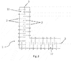
- the exemplary embodiment shown in Figures 2 and 3 comprises an insert (2) placed at the end of each arm (11, 12), parallel to the longitudinal directions thereof. Likewise, it comprises in each arm (11, 12) inserts (2) perpendicular to the longitudinal direction, of which one of every two consecutive inserts (2) comprises an end protruding through the surface that is in contact with the frame (F), while the inserts (2) alternating with the previous ones comprise one end protruding through the surface that is in contact with the partition (P).
- the width of the arms (11, 12) is equal to the thickness thereof, and the length thereof is four times the width itself, being able to be comprised between 0.1 and 0.5 times the height of the partition in the case of the vertical arm and between 0.1 and 0.5 times the length of the partition in the case of the horizontal arm.
- the embedded length of the inserts (2) of this exemplary embodiment is two thirds of the width of the arms (11, 12). It can also be seen how the external end of all the inserts (2) protrudes from the part one sixth of the length thereof, being smaller than the width of the mortar perpend and/or bed of the partition wherein it is inserted.
Landscapes
- Engineering & Computer Science (AREA)
- Architecture (AREA)
- Civil Engineering (AREA)
- Structural Engineering (AREA)
- Environmental & Geological Engineering (AREA)
- Business, Economics & Management (AREA)
- Emergency Management (AREA)
- Physics & Mathematics (AREA)
- Electromagnetism (AREA)
- Buildings Adapted To Withstand Abnormal External Influences (AREA)
Abstract
Description
- The object of the present invention application is the registration of a particularly convenient seismic isolator for conditioning buildings, both new and already built, with brick partitions according to the new seismic regulations.
- More specifically, the invention proposes the development of a seismic isolator, which, due to its particular arrangement, makes it possible to reduce the interaction which is produced between the brick partitions and the resistant structure of buildings due to the seismic activity.
- The inner partitions which compartmentalise the spaces of a building have a significant influence on the seismic behaviour of the latter. Due to the fact that the overall structure is stiffened as a whole when building the partitions, the seismic response is different from the one foreseen in the calculations, which are performed without considering the inner partitions. The drift of each floor of the building produces compression connecting rods in the partitions, the ends of which end at the head and base of the pillars that make up each closed frame, being able to lead to unforeseen structural failures.
- Current regulations indicate that masonry partitions which have not been taken into account in the calculations of the seismic response must be seismically isolated from the rest of the structure so that they do not influence the seismic response of the building.
- Elements configured to isolate partitions from the structural frames surrounding them are known in the current state of the art. For example, patent documents
CN102268900A andES2524844A1 - However, both the mortar placed between the elements and the side-to-side through rods also transfer some of the loads from the structure to the partition, reducing the isolating effect of the flexible parts and forming a flow of forces through the mortar and/or the through rods resulting in the formation of a portion of the initial connecting rod.
- Therefore, there is still a need for a seismic isolator for new and already built buildings which is inexpensive to manufacture and install, the matrix of flexible material of which has continuous contact with the building structure, preventing the existence of mortar between the elements, and which does not have stiff side-to-side through elements which can transmit forces from the structure to the rest of the brick partition. The present invention contributes to solving the existing deficiency.
- The present invention has been developed in order to provide a seismic isolator which is configured as a novelty within the field of application and which solves the aforementioned drawbacks, particularly convenient for the seismic protection of already built buildings made up of at least one resistant element in the form of a frame with a brick partition inside.
- The seismic isolator object of this invention corresponds to a single monobloc part formed from a material more flexible than the frame and than the bricks in the partition, for example, polymers such as rubber, polyurethane or EVA. The present seismic isolator is characterised in that it comprises two arms arranged at a right angle, one to be situated between the frame and the partition in a vertical direction and the other to be situated between the frame and the partition in a horizontal direction in its condition of use. The thickness of the isolator in the direction perpendicular to the plane of the partition can be between 0.5 to 1.5 times the thickness of the bricks. The width of each arm can be equal to or greater than one third of the height of a single brick. The length of each arm can be equal to or greater than three times the width of the arm itself, being at the same time a portion of the corresponding dimension of the partition, with the vertical arm having a length of between 0.1 and 0.5 times the height of the partition and the horizontal arm a length of between 0.1 and 0.5 times the length of the partition.
- Thanks to this configuration, the seismic isolator of the present invention maintains continuous contact with the structure of the building and thus enables damping throughout the entire element, seismically isolating the corner and sides of the partition in a more suitable manner than in the methods existing in the state of the art. If a seismic isolator is placed in each corner of the partition, the interaction which is produced with the structure of the building is greatly reduced. Each L-shaped part is deformed as a consequence of the displacement of the structure, preventing the brick partition from being loaded. Moreover, as it is an integral part, manufacturing, transportation and installation costs are reduced with respect to brick-shaped isolating elements, especially in already built partitions.
- In order to promote balanced damping throughout the entire element, the width of at least one of the arms can be larger in the area close to the joint with the other arm and be smaller in the area of the end of the arm.
- In order to interlock the part with the structure and with the partition, the present isolator may comprise at least one insert. One of the ends of this insert will be embedded in the part at a length less than or equal to four fifths of the width of the arm in the same direction as the insert. The other end of the insert will be able to protrude from one of the surfaces of the isolator perpendicular to the plane of the partition at a length less than or equal to the width of the perpend and/or of the bed existing in the partition.
- In this sense, the end of each arm can comprise an insert placed parallel to the longitudinal direction of the corresponding arm. Likewise, each arm can comprise at least one insert perpendicular to the longitudinal direction of the arm itself. Preferably, the isolator comprises one of every two consecutive perpendicular inserts with one end protruding through the surface that is in contact with the frame or structure of the building. Likewise, the inserts alternating with the previous ones comprise one end protruding through the surface that is in contact with the partition. This latter configuration achieves an interlocking of the isolator with the frame and with the partition in a distributed manner.
- The material of the inserts can be any stiff and resistant material in relative terms compared to the base material of the isolator, for example it can be steel or any polymer which satisfies said feature.
- Thanks to this configuration, the present seismic isolator in its condition of use has continuous contact with the structure of the building and does not present elements that transmit large forces in relative terms from the structure to the brick partition, in other words, which inhibit the isolating effect (such as mortar or through rods). The tensions in the partition are reduced by hindering the formation of compression connecting rods, thereby protecting the partition and reducing economic and human losses associated with partition breakage. As an advantage which must also be taken into account, the isolator is inexpensive to install, especially in already built partitions, since it is enough to simply make a groove or recess in the corner of the partition, place the isolator and fill the gaps existing between the isolator and the partition and between the isolator and the structural frame with masonry mortar (which does not generate new loads because it deforms together with the isolator, since it is a continuous part with flexibility). Likewise, the seismic isolator itself is inexpensive to manufacture even with inserts, which can be easily added after the formation of the arms made of flexible material.
-
-
Figure 1 is a schematic elevation view of the seismic isolator of the present invention in its condition of use. -
Figure 2 is a perspective view of an exemplary embodiment of the seismic isolator of the present invention. -
Figure 3 is a schematic view of an exemplary embodiment of the seismic isolator of the present invention. - In light of the aforementioned figures, and in accordance with the adopted numbering, one may observe therein a preferred exemplary embodiment of the invention, comprising the parts and elements indicated and described in detail below.
- As shown in
Figure 1 , the preferred embodiment of the seismic isolator of the present invention consists of a single monobloc part (1) comprising two arms (11, 12) arranged at a right angle, one to be situated between the frame (F) and the partition (P) in a vertical direction and another to be situated between the frame (F) and the partition (P) in a horizontal direction. In the exemplary embodiment shown inFigure 1 , the arms (11, 12) have a width somewhat smaller than the height of the bricks of the partition (P), the horizontal arm has a length ten times the width of the isolator and the vertical arm nine times the width of the isolator. This figure shows the mortar (m) placed around the monobloc part (1), which fills the gaps between it and the frame (F), and between it and the partition (P). - The exemplary embodiment shown in
Figures 2 and3 comprises an insert (2) placed at the end of each arm (11, 12), parallel to the longitudinal directions thereof. Likewise, it comprises in each arm (11, 12) inserts (2) perpendicular to the longitudinal direction, of which one of every two consecutive inserts (2) comprises an end protruding through the surface that is in contact with the frame (F), while the inserts (2) alternating with the previous ones comprise one end protruding through the surface that is in contact with the partition (P). In this case, the width of the arms (11, 12) is equal to the thickness thereof, and the length thereof is four times the width itself, being able to be comprised between 0.1 and 0.5 times the height of the partition in the case of the vertical arm and between 0.1 and 0.5 times the length of the partition in the case of the horizontal arm. As seen inFigure 3 in dotted lines, the embedded length of the inserts (2) of this exemplary embodiment is two thirds of the width of the arms (11, 12). It can also be seen how the external end of all the inserts (2) protrudes from the part one sixth of the length thereof, being smaller than the width of the mortar perpend and/or bed of the partition wherein it is inserted.
Claims (6)
- A corner seismic isolator for the seismic protection of buildings, both new and already built, comprising at least one resistant element in the form of a frame (F) with a brick partition (P) inside, the isolator consisting of a single monobloc part (1) formed from a material more flexible than the frame (F) and than the bricks of the partition (P), characterised in that two arms (11, 12) arranged at a right angle, one to be situated between the frame (F) and the partition (P) in a vertical direction and the other to be situated between the frame (F) and the partition (P) in a horizontal direction, the thickness of which in the direction perpendicular to the plane of the partition (P) is between 0.5 to 1.5 times the thickness of the bricks in the partition (P), with the width of the arms (11, 12) being equal to or greater than one third of the height of a single brick in the partition (P) and the length thereof equal to or greater than three times the width of the arm itself (11, 12), with the length thereof, in turn, being a portion than the corresponding dimension of the partition, with the vertical arm having a length of between 0.1 and 0.5 times the height of the partition and the horizontal arm a length of between 0.1 and 0.5 times the length of the partition
- The isolator according to claim 1, characterised in that it comprises at least one insert (2), which has one end embedded in the part (1), this end having a length less than or equal to four fifths of the width of the arm itself (11, 12), and the other end protruding from one of the surfaces of the isolator perpendicular to the plane of the partition (P).
- The isolator according to claim 2, characterised in that the end of each arm (11, 12) comprises an insert (2) placed parallel to the longitudinal direction of the corresponding arm (11, 12).
- The isolator according to claim 2 or 3, characterised in that each arm (11, 12) comprises at least one insert (2) perpendicular to the longitudinal direction of the corresponding arm (11, 12).
- The isolator according to claim 4, characterised in that one of every two consecutive perpendicular inserts (2) comprises one end protruding through the surface that is in contact with the frame (F) and the inserts (2) alternating with the previous ones comprise one end protruding through the surface that is in contact with the partition (P).
- The isolator according to any of the preceding claims, characterised in that the width of at least one of the arms (11, 12) is larger in the area close to the joint with the other arm (11, 12) and is smaller in the area of the end itself.
Applications Claiming Priority (2)
| Application Number | Priority Date | Filing Date | Title |
|---|---|---|---|
| ES201831030A ES2708385B2 (en) | 2018-10-24 | 2018-10-24 | Seismic corner isolator for seismic adaptation of buildings. |
| PCT/ES2019/070694 WO2020084176A1 (en) | 2018-10-24 | 2019-10-11 | Corner seismic isolator for seismic protection of buildings |
Publications (4)
| Publication Number | Publication Date |
|---|---|
| EP3872273A1 true EP3872273A1 (en) | 2021-09-01 |
| EP3872273A4 EP3872273A4 (en) | 2022-08-03 |
| EP3872273B1 EP3872273B1 (en) | 2024-10-30 |
| EP3872273C0 EP3872273C0 (en) | 2024-10-30 |
Family
ID=65985738
Family Applications (1)
| Application Number | Title | Priority Date | Filing Date |
|---|---|---|---|
| EP19876380.7A Active EP3872273B1 (en) | 2018-10-24 | 2019-10-11 | Corner seismic isolator for seismic protection of buildings |
Country Status (6)
| Country | Link |
|---|---|
| US (1) | US20220010574A1 (en) |
| EP (1) | EP3872273B1 (en) |
| CL (1) | CL2021001043A1 (en) |
| CO (1) | CO2021005170A2 (en) |
| ES (1) | ES2708385B2 (en) |
| WO (1) | WO2020084176A1 (en) |
Cited By (1)
| Publication number | Priority date | Publication date | Assignee | Title |
|---|---|---|---|---|
| ES2963020A1 (en) * | 2023-11-06 | 2024-03-22 | Univ Valencia Politecnica | NON-STRUCTURAL, SEISMICALLY INSULATED CONSTRUCTION PLATE AND NON-STRUCTURAL, SEISMICALLY ISOLATED CONSTRUCTION PANEL WHICH COMPRISES SAID PLATE (Machine-translation by Google Translate, not legally binding) |
Family Cites Families (9)
| Publication number | Priority date | Publication date | Assignee | Title |
|---|---|---|---|---|
| FR2690940A1 (en) * | 1992-05-06 | 1993-11-12 | Seyve Daniel | Construction using base blocks - uses blocks made from slightly compressible, fireproofed expanded plastics having PVC tube guides fitting in blind holes |
| CN101122150B (en) * | 2007-08-31 | 2010-06-02 | 广东省建筑设计研究院 | A shock absorbing wall and its construction method |
| CN102071762B (en) * | 2011-01-10 | 2012-05-30 | 东南大学 | Wall body built by self-embedding insulation blocks |
| CN102268900B (en) | 2011-06-11 | 2012-12-19 | 广州大学 | Damped anti-seismic filling wallboard for framework |
| ES2524844B1 (en) * | 2014-03-25 | 2015-09-23 | Universitat Politècnica De València | Building anti-seismic insulator |
| CN205134528U (en) * | 2015-10-27 | 2016-04-06 | 杨佳伟 | Elasticity power consumption bulk filling structure antidetonation frame |
| CN105507454B (en) * | 2016-02-27 | 2017-10-10 | 中国地震局工程力学研究所 | One kind deformation controllable type frame wall filled with masonry and the practice |
| CN105937278B (en) * | 2016-06-06 | 2019-06-07 | 河北建筑工程学院 | A kind of assembly concrete frame wall filled with masonry system and its construction method |
| KR101787375B1 (en) * | 2017-02-21 | 2017-10-19 | 유홍희 | Earthquake-resistance assembling block unit for non-bearing wall sturucture and unreinforced masonry structure |
-
2018
- 2018-10-24 ES ES201831030A patent/ES2708385B2/en active Active
-
2019
- 2019-10-11 US US17/288,005 patent/US20220010574A1/en not_active Abandoned
- 2019-10-11 WO PCT/ES2019/070694 patent/WO2020084176A1/en not_active Ceased
- 2019-10-11 EP EP19876380.7A patent/EP3872273B1/en active Active
-
2021
- 2021-04-22 CO CONC2021/0005170A patent/CO2021005170A2/en unknown
- 2021-04-23 CL CL2021001043A patent/CL2021001043A1/en unknown
Cited By (1)
| Publication number | Priority date | Publication date | Assignee | Title |
|---|---|---|---|---|
| ES2963020A1 (en) * | 2023-11-06 | 2024-03-22 | Univ Valencia Politecnica | NON-STRUCTURAL, SEISMICALLY INSULATED CONSTRUCTION PLATE AND NON-STRUCTURAL, SEISMICALLY ISOLATED CONSTRUCTION PANEL WHICH COMPRISES SAID PLATE (Machine-translation by Google Translate, not legally binding) |
Also Published As
| Publication number | Publication date |
|---|---|
| WO2020084176A1 (en) | 2020-04-30 |
| ES2708385B2 (en) | 2020-12-23 |
| ES2708385A1 (en) | 2019-04-09 |
| EP3872273B1 (en) | 2024-10-30 |
| CL2021001043A1 (en) | 2021-09-20 |
| CO2021005170A2 (en) | 2021-04-30 |
| EP3872273C0 (en) | 2024-10-30 |
| US20220010574A1 (en) | 2022-01-13 |
| EP3872273A4 (en) | 2022-08-03 |
Similar Documents
| Publication | Publication Date | Title |
|---|---|---|
| US10000923B2 (en) | Fire blocking reveal | |
| US9752318B2 (en) | Fire blocking reveal | |
| US9435118B2 (en) | Interlocking masonry blocks for construction of load bearing and non-load bearing walls | |
| CA2897558C (en) | Composite building panel | |
| US9822529B1 (en) | Interlocking and insulated construction blocks | |
| US4004385A (en) | Building structure using concrete blocks | |
| US20100162649A1 (en) | Building block system | |
| KR102373415B1 (en) | curtain wall | |
| JP2017511849A (en) | Seismic building connection and seismic staircase system | |
| KR101323110B1 (en) | Sandwich panel | |
| EP3872273B1 (en) | Corner seismic isolator for seismic protection of buildings | |
| JP2014129682A (en) | Wall surface structure of brick wall, and construction method of brick wall | |
| JP6386968B2 (en) | Thermal insulation structure of building | |
| KR102249058B1 (en) | Prefabricated wall | |
| KR20220112916A (en) | A prefabricated wall using concrete structure | |
| EP3130715A1 (en) | Anti-seismic, insulating construction element | |
| KR20120009744A (en) | Green Timberwell bearing wall structure for construction | |
| KR102771205B1 (en) | Assembly block structure of drywall and manufacturing method thereof | |
| KR101533778B1 (en) | Module unit assembly structure for modular buildings | |
| JP6684536B2 (en) | Buildings and warehouses | |
| JP6404183B2 (en) | Thermal insulation structure of outer wall | |
| KR102388844B1 (en) | finishing block filling a gap between the outdoor bar of the vertical bar and the outdoor bar of the horizontal bar of the curtain wall | |
| KR102699065B1 (en) | Prefabricated house panel and prefabricated structure including the same | |
| JP6184338B2 (en) | Buildings with different top floor frames and lower floor frames | |
| KR20110090629A (en) | Redundant partition bulkhead structural system for variable plan design |
Legal Events
| Date | Code | Title | Description |
|---|---|---|---|
| STAA | Information on the status of an ep patent application or granted ep patent |
Free format text: STATUS: THE INTERNATIONAL PUBLICATION HAS BEEN MADE |
|
| PUAI | Public reference made under article 153(3) epc to a published international application that has entered the european phase |
Free format text: ORIGINAL CODE: 0009012 |
|
| STAA | Information on the status of an ep patent application or granted ep patent |
Free format text: STATUS: REQUEST FOR EXAMINATION WAS MADE |
|
| 17P | Request for examination filed |
Effective date: 20210419 |
|
| AK | Designated contracting states |
Kind code of ref document: A1 Designated state(s): AL AT BE BG CH CY CZ DE DK EE ES FI FR GB GR HR HU IE IS IT LI LT LU LV MC MK MT NL NO PL PT RO RS SE SI SK SM TR |
|
| DAV | Request for validation of the european patent (deleted) | ||
| A4 | Supplementary search report drawn up and despatched |
Effective date: 20220706 |
|
| RIC1 | Information provided on ipc code assigned before grant |
Ipc: E04B 1/36 20060101ALI20220630BHEP Ipc: E04B 2/12 20060101ALI20220630BHEP Ipc: E04H 9/02 20060101ALI20220630BHEP Ipc: E04B 2/56 20060101ALI20220630BHEP Ipc: E04B 1/98 20060101AFI20220630BHEP |
|
| GRAP | Despatch of communication of intention to grant a patent |
Free format text: ORIGINAL CODE: EPIDOSNIGR1 |
|
| STAA | Information on the status of an ep patent application or granted ep patent |
Free format text: STATUS: GRANT OF PATENT IS INTENDED |
|
| RIC1 | Information provided on ipc code assigned before grant |
Ipc: E04B 1/36 20060101ALI20240430BHEP Ipc: E04B 2/12 20060101ALI20240430BHEP Ipc: E04H 9/02 20060101ALI20240430BHEP Ipc: E04B 2/56 20060101ALI20240430BHEP Ipc: E04B 1/98 20060101AFI20240430BHEP |
|
| INTG | Intention to grant announced |
Effective date: 20240529 |
|
| GRAS | Grant fee paid |
Free format text: ORIGINAL CODE: EPIDOSNIGR3 |
|
| GRAA | (expected) grant |
Free format text: ORIGINAL CODE: 0009210 |
|
| STAA | Information on the status of an ep patent application or granted ep patent |
Free format text: STATUS: THE PATENT HAS BEEN GRANTED |
|
| AK | Designated contracting states |
Kind code of ref document: B1 Designated state(s): AL AT BE BG CH CY CZ DE DK EE ES FI FR GB GR HR HU IE IS IT LI LT LU LV MC MK MT NL NO PL PT RO RS SE SI SK SM TR |
|
| REG | Reference to a national code |
Ref country code: GB Ref legal event code: FG4D |
|
| REG | Reference to a national code |
Ref country code: CH Ref legal event code: EP |
|
| REG | Reference to a national code |
Ref country code: IE Ref legal event code: FG4D |
|
| REG | Reference to a national code |
Ref country code: DE Ref legal event code: R096 Ref document number: 602019061302 Country of ref document: DE |
|
| U01 | Request for unitary effect filed |
Effective date: 20241107 |
|
| U07 | Unitary effect registered |
Designated state(s): AT BE BG DE DK EE FI FR IT LT LU LV MT NL PT RO SE SI Effective date: 20241115 |
|
| PG25 | Lapsed in a contracting state [announced via postgrant information from national office to epo] |
Ref country code: HR Free format text: LAPSE BECAUSE OF FAILURE TO SUBMIT A TRANSLATION OF THE DESCRIPTION OR TO PAY THE FEE WITHIN THE PRESCRIBED TIME-LIMIT Effective date: 20241030 Ref country code: IS Free format text: LAPSE BECAUSE OF FAILURE TO SUBMIT A TRANSLATION OF THE DESCRIPTION OR TO PAY THE FEE WITHIN THE PRESCRIBED TIME-LIMIT Effective date: 20250228 |
|
| PG25 | Lapsed in a contracting state [announced via postgrant information from national office to epo] |
Ref country code: ES Free format text: LAPSE BECAUSE OF FAILURE TO SUBMIT A TRANSLATION OF THE DESCRIPTION OR TO PAY THE FEE WITHIN THE PRESCRIBED TIME-LIMIT Effective date: 20241030 |
|
| PG25 | Lapsed in a contracting state [announced via postgrant information from national office to epo] |
Ref country code: NO Free format text: LAPSE BECAUSE OF FAILURE TO SUBMIT A TRANSLATION OF THE DESCRIPTION OR TO PAY THE FEE WITHIN THE PRESCRIBED TIME-LIMIT Effective date: 20250130 |
|
| PG25 | Lapsed in a contracting state [announced via postgrant information from national office to epo] |
Ref country code: GR Free format text: LAPSE BECAUSE OF FAILURE TO SUBMIT A TRANSLATION OF THE DESCRIPTION OR TO PAY THE FEE WITHIN THE PRESCRIBED TIME-LIMIT Effective date: 20250131 |
|
| PG25 | Lapsed in a contracting state [announced via postgrant information from national office to epo] |
Ref country code: PL Free format text: LAPSE BECAUSE OF FAILURE TO SUBMIT A TRANSLATION OF THE DESCRIPTION OR TO PAY THE FEE WITHIN THE PRESCRIBED TIME-LIMIT Effective date: 20241030 |
|
| PG25 | Lapsed in a contracting state [announced via postgrant information from national office to epo] |
Ref country code: RS Free format text: LAPSE BECAUSE OF FAILURE TO SUBMIT A TRANSLATION OF THE DESCRIPTION OR TO PAY THE FEE WITHIN THE PRESCRIBED TIME-LIMIT Effective date: 20250130 |
|
| PG25 | Lapsed in a contracting state [announced via postgrant information from national office to epo] |
Ref country code: SM Free format text: LAPSE BECAUSE OF FAILURE TO SUBMIT A TRANSLATION OF THE DESCRIPTION OR TO PAY THE FEE WITHIN THE PRESCRIBED TIME-LIMIT Effective date: 20241030 |
|
| PG25 | Lapsed in a contracting state [announced via postgrant information from national office to epo] |
Ref country code: SK Free format text: LAPSE BECAUSE OF FAILURE TO SUBMIT A TRANSLATION OF THE DESCRIPTION OR TO PAY THE FEE WITHIN THE PRESCRIBED TIME-LIMIT Effective date: 20241030 |
|
| PG25 | Lapsed in a contracting state [announced via postgrant information from national office to epo] |
Ref country code: CZ Free format text: LAPSE BECAUSE OF FAILURE TO SUBMIT A TRANSLATION OF THE DESCRIPTION OR TO PAY THE FEE WITHIN THE PRESCRIBED TIME-LIMIT Effective date: 20241030 |
|
| PLBE | No opposition filed within time limit |
Free format text: ORIGINAL CODE: 0009261 |
|
| STAA | Information on the status of an ep patent application or granted ep patent |
Free format text: STATUS: NO OPPOSITION FILED WITHIN TIME LIMIT |
|
| 26N | No opposition filed |
Effective date: 20250731 |
|
| U20 | Renewal fee for the european patent with unitary effect paid |
Year of fee payment: 7 Effective date: 20251021 |