EP3871819A1 - Inclined structure and manufacturing method therefor - Google Patents
Inclined structure and manufacturing method therefor Download PDFInfo
- Publication number
- EP3871819A1 EP3871819A1 EP19875062.2A EP19875062A EP3871819A1 EP 3871819 A1 EP3871819 A1 EP 3871819A1 EP 19875062 A EP19875062 A EP 19875062A EP 3871819 A1 EP3871819 A1 EP 3871819A1
- Authority
- EP
- European Patent Office
- Prior art keywords
- build
- layers
- base metal
- inclined structure
- base
- Prior art date
- Legal status (The legal status is an assumption and is not a legal conclusion. Google has not performed a legal analysis and makes no representation as to the accuracy of the status listed.)
- Pending
Links
Images



Classifications
-
- B—PERFORMING OPERATIONS; TRANSPORTING
- B23—MACHINE TOOLS; METAL-WORKING NOT OTHERWISE PROVIDED FOR
- B23K—SOLDERING OR UNSOLDERING; WELDING; CLADDING OR PLATING BY SOLDERING OR WELDING; CUTTING BY APPLYING HEAT LOCALLY, e.g. FLAME CUTTING; WORKING BY LASER BEAM
- B23K9/00—Arc welding or cutting
- B23K9/04—Welding for other purposes than joining, e.g. built-up welding
- B23K9/042—Built-up welding on planar surfaces
-
- B—PERFORMING OPERATIONS; TRANSPORTING
- B22—CASTING; POWDER METALLURGY
- B22F—WORKING METALLIC POWDER; MANUFACTURE OF ARTICLES FROM METALLIC POWDER; MAKING METALLIC POWDER; APPARATUS OR DEVICES SPECIALLY ADAPTED FOR METALLIC POWDER
- B22F10/00—Additive manufacturing of workpieces or articles from metallic powder
- B22F10/20—Direct sintering or melting
- B22F10/22—Direct deposition of molten metal
-
- B—PERFORMING OPERATIONS; TRANSPORTING
- B22—CASTING; POWDER METALLURGY
- B22F—WORKING METALLIC POWDER; MANUFACTURE OF ARTICLES FROM METALLIC POWDER; MAKING METALLIC POWDER; APPARATUS OR DEVICES SPECIALLY ADAPTED FOR METALLIC POWDER
- B22F10/00—Additive manufacturing of workpieces or articles from metallic powder
- B22F10/20—Direct sintering or melting
- B22F10/28—Powder bed fusion, e.g. selective laser melting [SLM] or electron beam melting [EBM]
-
- B—PERFORMING OPERATIONS; TRANSPORTING
- B22—CASTING; POWDER METALLURGY
- B22F—WORKING METALLIC POWDER; MANUFACTURE OF ARTICLES FROM METALLIC POWDER; MAKING METALLIC POWDER; APPARATUS OR DEVICES SPECIALLY ADAPTED FOR METALLIC POWDER
- B22F10/00—Additive manufacturing of workpieces or articles from metallic powder
- B22F10/30—Process control
- B22F10/38—Process control to achieve specific product aspects, e.g. surface smoothness, density, porosity or hollow structures
-
- B—PERFORMING OPERATIONS; TRANSPORTING
- B23—MACHINE TOOLS; METAL-WORKING NOT OTHERWISE PROVIDED FOR
- B23K—SOLDERING OR UNSOLDERING; WELDING; CLADDING OR PLATING BY SOLDERING OR WELDING; CUTTING BY APPLYING HEAT LOCALLY, e.g. FLAME CUTTING; WORKING BY LASER BEAM
- B23K26/00—Working by laser beam, e.g. welding, cutting or boring
- B23K26/34—Laser welding for purposes other than joining
- B23K26/342—Build-up welding
-
- B—PERFORMING OPERATIONS; TRANSPORTING
- B33—ADDITIVE MANUFACTURING TECHNOLOGY
- B33Y—ADDITIVE MANUFACTURING, i.e. MANUFACTURING OF THREE-DIMENSIONAL [3D] OBJECTS BY ADDITIVE DEPOSITION, ADDITIVE AGGLOMERATION OR ADDITIVE LAYERING, e.g. BY 3D PRINTING, STEREOLITHOGRAPHY OR SELECTIVE LASER SINTERING
- B33Y10/00—Processes of additive manufacturing
-
- B—PERFORMING OPERATIONS; TRANSPORTING
- B33—ADDITIVE MANUFACTURING TECHNOLOGY
- B33Y—ADDITIVE MANUFACTURING, i.e. MANUFACTURING OF THREE-DIMENSIONAL [3D] OBJECTS BY ADDITIVE DEPOSITION, ADDITIVE AGGLOMERATION OR ADDITIVE LAYERING, e.g. BY 3D PRINTING, STEREOLITHOGRAPHY OR SELECTIVE LASER SINTERING
- B33Y80/00—Products made by additive manufacturing
-
- Y—GENERAL TAGGING OF NEW TECHNOLOGICAL DEVELOPMENTS; GENERAL TAGGING OF CROSS-SECTIONAL TECHNOLOGIES SPANNING OVER SEVERAL SECTIONS OF THE IPC; TECHNICAL SUBJECTS COVERED BY FORMER USPC CROSS-REFERENCE ART COLLECTIONS [XRACs] AND DIGESTS
- Y02—TECHNOLOGIES OR APPLICATIONS FOR MITIGATION OR ADAPTATION AGAINST CLIMATE CHANGE
- Y02P—CLIMATE CHANGE MITIGATION TECHNOLOGIES IN THE PRODUCTION OR PROCESSING OF GOODS
- Y02P10/00—Technologies related to metal processing
- Y02P10/25—Process efficiency
Definitions
- the present invention relates to an inclined structure extending in an oblique direction from a surface of a base metal, and a method of manufacturing the inclined structure.
- An inclined structure extending in an oblique direction from a surface of a base metal can be manufactured by build-up welding.
- FIG. 5 of PTL 1 shows that the inclined structure is manufactured by MIG (Metal Inert Gas) welding.
- PTL 1 describes that the inclined structure can be manufactured without a supporting body when an angle of the inclined structure to a perpendicular line of the surface of the base metal is 33° or less (see paragraph 0022 in Detailed Description of the Invention). In other words, when an angle between the surface of the base metal and an inclination direction of the inclined structure is less than 57°, manufacturing the inclined structure without the supporting body is not realized.
- An object of the present invention is to provide a method of manufacturing an inclined structure having any inclination direction without a supporting body, and an inclined structure manufactured by such manufacturing method.
- a method of manufacturing an inclined structure is a method of manufacturing an inclined structure extending in an oblique direction from a surface of a base metal, the method including: forming a base portion by stacking a plurality of build-up layers on the surface of the base metal, each of the plurality of build-up layers being formed by a plurality of beads, the base portion including a reference surface inclined at an opposite side of the oblique direction across a perpendicular line of the surface of the base metal; and forming a projecting portion by stacking a plurality of build-up layers on the reference surface of the base portion, each of the plurality of build-up layers being formed by a plurality of beads, the projecting portion extending in the oblique direction from the base portion.
- the reference surface inclined relative to the surface of the base metal is formed at first, and then, the plurality of build-up layers are staked on the reference surface. Therefore, the inclined structure having any inclination direction can be manufactured without a supporting body.
- the inclined structure may have an annular shape which increases or decreases in diameter in a direction away from the base metal.
- Stacking of the plurality of build-up layers on the surface of the base metal and stacking of the plurality of build-up layers on the reference surface of the base portion may be performed by laser metal deposition. According to this configuration, since heat input to the base metal becomes small, a heat affected zone (HAZ) of the base metal can be made small. Moreover, since the stacking of the build-up layers on the reference surface of the base portion is also performed by the laser metal deposition, the base portion and the projecting portion can be consecutively formed.
- HZ heat affected zone
- Powder may be used as a welding material in the laser metal deposition.
- each of the build-up layers may be formed such that the beads are arranged in order from a side close to the base metal.
- the build-up layers are stacked on the reference surface by forming each of the build-up layers such that the beads are arranged in order from a side far from the base metal
- the second and following beads when forming the second and following beads, the powder scattering around a molten pool tends to remain between the existing bead and the base metal.
- the second and following beads can be formed with high quality in each of the build-up layers.
- each of the build-up layers may be formed such that the beads are arranged in order from a side close to the reference surface. According to this configuration, the reference surface having small unevenness can be formed.
- an inclined structure of the present invention is an inclined structure extending in an oblique direction from a surface of a base metal, the inclined structure including: a base portion made of metal and formed on the surface of the base metal, the base portion including crystal grains which form a columnar shape along a direction vertical to the surface of the base metal; and a projecting portion made of metal and extending in the oblique direction from the base portion, the projecting portion including crystal grains which form a columnar shape along the oblique direction.
- the inclined structure having any inclination direction can be manufactured without the supporting body.
- an inclined structure 2 extending in an oblique direction D from a surface 11 of a base metal 1 is manufactured by a manufacturing method according to one embodiment of the present invention.
- the base metal 1 has a disc shape including a through hole 12 at a center thereof.
- the shape of the base metal 1 is not limited to this.
- the base metal 1 may have any shape (for example, a bowl shape).
- the inclined structure 2 has an annular shape which decreases in diameter in a direction away from the base metal 1.
- the inclined structure 2 is a tapered peripheral wall. Therefore, the above-described oblique direction D is a direction along a conical surface.
- the inclined structure 2 may have an annular shape which increases in diameter in the direction away from the base metal 1. Or, the inclined structure 2 does not necessarily have to have an annular shape and may have an inclined plate shape or an inclined columnar shape.
- the inclined structure 2 includes a base portion 3 and a projecting portion 5.
- the base portion 3 is formed on the surface 11 of the base metal 1.
- the projecting portion 5 extends in the oblique direction D from the base portion 3.
- the base portion 3 and the projecting portion 5 are made of metal.
- a sectional shape of the base portion 3 is a triangular shape as shown in FIG. 3
- a sectional shape of the projecting portion 5 is a rectangular shape as shown in FIG. 5
- the sectional shape of the base portion 3 is not especially limited as long as the base portion 3 includes a below-described reference surface 31.
- the sectional shape of the base portion 3 may be a trapezoidal shape or may be a fan shape having two sides that are the surface 11 of the base metal 1 and the reference surface 31.
- the sectional shape of the projecting portion 4 is not especially limited and may be a trapezoidal shape or a triangular shape.
- the base portion 3 is formed by stacking a plurality of (six in the illustrated example) build-up layers 4A to 4F on the surface 11 of the base metal 1.
- the build-up layer 4F located at an uppermost position is formed by a single bead 41, and each of the other build-up layers 4A to 4E is formed by a plurality of beads 41.
- Each of all the beads 41 has an annular shape concentric with the inclined structure 2.
- the beads 41 are arranged in parallel with the surface 11 of the base metal 1.
- the base portion 3 includes the reference surface 31 inclined at an opposite side of the oblique direction D across a perpendicular line of the surface 11 of the base metal 1.
- the reference surface 31 is formed by the beads 41 which are located closest to the oblique direction D in the respective build-up layers 4A to 4F.
- the stacking of the build-up layers 4A to 4F on the surface 11 of the base metal 1 is performed by laser metal deposition (LMD).
- LMD laser metal deposition
- the stacking of the build-up layers 4A to 4F on the surface 11 of the base metal 1 may be performed by another method, such as MIG welding or electron beam welding.
- a welding material and a shielding gas are supplied from a nozzle (not shown) toward the surface 11 of the base metal 1 or a surface of the build-up layer formed most recently, and the surface 11 of the base metal 1 or the surface of the build-up layer formed most recently is irradiated with laser beam.
- a molten pool is generated.
- the supply of the welding material and the shielding gas and the irradiation of the laser beam are performed while rotating the base metal 1 in a horizontal state, and the above molten pool becomes the bead 41.
- powder is used as the welding material.
- the welding material may be a wire.
- each of the build-up layers 4A to 4F When stacking the build-up layers 4A to 4F on the surface 11 of the base metal 1, it is desirable to form each of the build-up layers 4A to 4F such that the beads 41 are arranged in order from a side close to the reference surface 31 of the base portion 3 (in FIG. 3 , from a right side to a left side). This is because: the reference surface 31 having small unevenness can be formed; and the reference surface 31 can be formed at an accurate angle to the surface 11 of the base metal 1.
- the base metal 1 is inclined such that the reference surface 31 of the base portion 3 becomes horizontal at a lowermost point of the annular base portion 3. Then, the reference surface 31 is irradiated with laser from the nozzle used in the LMD to be smoothed.
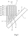
- the projecting portion 5 is formed by stacking a plurality of (ten in the illustrated example) build-up layers 6A to 6J on the reference surface 31 of the base portion 3.
- the sectional shape of the projecting portion 5 is the rectangular shape as described above, each of all the build-up layers 6A to 6J is formed by a plurality of beads 61.
- Each of all the beads 61 has an annular shape concentric with the inclined structure 2.
- the beads 61 are arranged in parallel with the reference surface 31 of the base portion 3.
- the stacking of the build-up layers 6A to 6J on the reference surface 31 of the base portion 3 is performed by the LMD.
- the stacking of the build-up layers 6A to 6J on the reference surface 31 of the base portion 3 may be performed by another method, such as MIG welding or electron beam welding.
- the welding material and the shielding gas are supplied from the nozzle (not shown) toward the reference surface 31 of the base portion 3 or a surface of the build-up layer formed most recently, and the reference surface 31 of the base portion 3 or the surface of the build-up layer formed most recently is irradiated with the laser beam.
- the molten pool is generated.
- the supply of the welding material and the shielding gas and the irradiation of the laser beam are performed while rotating the base metal 1 in an inclined state, and the above molten pool becomes the bead 61.
- powder is used as the welding material.
- the welding material may be a wire.
- each of the build-up layers 6A to 6J When stacking the build-up layers 6A to 6J on the reference surface 31 of the base portion 3, it is desirable to form each of the build-up layers 6A to 6J such that the beads 61 are arranged in order from a side close to the base metal 1 (in FIG. 5 , from a right side to a left side).
- the build-up layers 6A to 6J are stacked on the reference surface 31 of the base portion 3 by forming each of the build-up layers 6A to 6J such that the beads 61 are arranged in order from a side far from the base metal 1
- the powder scattering around the molten pool tends to remain between the existing bead and the base metal 1.
- the beads 61 when the beads 61 are arranged in order from the side close to the base metal 1, the second and following beads can be formed with high quality in each of the build-up layers 6A to 6J.
- the reference surface 31 inclined relative to the surface 11 of the base metal 1 is formed at first, and then, the plurality of build-up layers 6A to 6J are stacked on the reference surface 31. Therefore, the inclined structure 2 having any inclination direction can be manufactured without a supporting body.
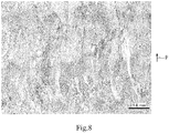
- FIG. 6 when the inclined structure is manufactured by stacking a plurality of build-up layers on the surface 11 of the base metal 1 such that the plurality of build-up layers are shifted little by little, crystal grains in the inclined structure form a columnar shape along a stacking direction (direction P vertical to the surface 11 of the base metal 1) as shown in FIG. 8 .
- crystal grain boundaries are arranged in a direction parallel to the surface 11 of the base metal 1. Therefore, creep strength in a build direction of the inclined structure is not so high.
- FIG. 6 schematically shows some of a large number of crystal grain boundaries (the same is true in FIG. 7 described below).
- FIG. 8 is an enlarged photograph taken after a cutting surface of the inclined structure is subjected to etching.
- the crystal grains in the base portion 3 form a columnar shape along the direction P vertical to the surface 11 of the base metal 1, and the crystal grains in the projecting portion 5 form a columnar shape along the build direction of the inclined structure 2.
- the crystal grain boundaries in the projecting portion are arranged in a direction vertical to the oblique direction D. Therefore, high creep strength can be obtained in the build direction of the inclined structure 2.
- the stacking of the build-up layers 4A to 4F on the surface 11 of the base metal 1 is performed by the LMD, heat input to the base metal 1 becomes small. Therefore, a heat affected zone (HAZ) of the base metal 1 can be made small.
- the stacking of the build-up layers 6A to 6J on the reference surface 31 of the base portion 3 is also performed by the LMD, the base portion and the projecting portion can be consecutively formed.
- each of the build-up layers 4A to 4F constituting the base portion 3 does not necessarily have to be formed such that the beads 41 are arranged in order from the side close to the reference surface 31 of the base portion 3.
- the order of the formation of the beads 41 may be reversed.
- each of the build-up layers 6A to 6J constituting the projecting portion 5 does not necessarily have to be formed such that the beads 61 are arranged in order from the side close to the base metal 1.
- the beads 61 located at both sides in each of the build-up layers 6A to 6J may be formed at first, and then, the beads 61 located inside may be formed.
Landscapes
- Engineering & Computer Science (AREA)
- Chemical & Material Sciences (AREA)
- Manufacturing & Machinery (AREA)
- Materials Engineering (AREA)
- Physics & Mathematics (AREA)
- Optics & Photonics (AREA)
- Plasma & Fusion (AREA)
- Mechanical Engineering (AREA)
- Automation & Control Theory (AREA)
- Laser Beam Processing (AREA)
Abstract
Description
- The present invention relates to an inclined structure extending in an oblique direction from a surface of a base metal, and a method of manufacturing the inclined structure.
- An inclined structure extending in an oblique direction from a surface of a base metal can be manufactured by build-up welding. For example,
FIG. 5 ofPTL 1 shows that the inclined structure is manufactured by MIG (Metal Inert Gas) welding. - Moreover,
PTL 1 describes that the inclined structure can be manufactured without a supporting body when an angle of the inclined structure to a perpendicular line of the surface of the base metal is 33° or less (see paragraph 0022 in Detailed Description of the Invention). In other words, when an angle between the surface of the base metal and an inclination direction of the inclined structure is less than 57°, manufacturing the inclined structure without the supporting body is not realized. - PTL 1:
Japanese Laid-Open Patent Application Publication No. 4-336304 - An object of the present invention is to provide a method of manufacturing an inclined structure having any inclination direction without a supporting body, and an inclined structure manufactured by such manufacturing method.
- To solve the above problem, a method of manufacturing an inclined structure according to the present invention is a method of manufacturing an inclined structure extending in an oblique direction from a surface of a base metal, the method including: forming a base portion by stacking a plurality of build-up layers on the surface of the base metal, each of the plurality of build-up layers being formed by a plurality of beads, the base portion including a reference surface inclined at an opposite side of the oblique direction across a perpendicular line of the surface of the base metal; and forming a projecting portion by stacking a plurality of build-up layers on the reference surface of the base portion, each of the plurality of build-up layers being formed by a plurality of beads, the projecting portion extending in the oblique direction from the base portion.
- According to the above configuration, the reference surface inclined relative to the surface of the base metal is formed at first, and then, the plurality of build-up layers are staked on the reference surface. Therefore, the inclined structure having any inclination direction can be manufactured without a supporting body.
- As shown in
FIG. 5 ofPTL 1, when the inclined structure is manufactured by stacking the plurality of build-up layers on the surface of the base metal such that the plurality of build-up layers are shifted little by little, crystal grains in the inclined structure form a columnar shape along a stacking direction (direction vertical to the surface of the base metal). Therefore, creep strength in a build direction of the inclined structure is not so high. On the other hand, in the inclined structure manufactured by the above manufacturing method, the crystal grains in the projecting portion of the inclined structure form a columnar shape along the build direction of the inclined structure. Therefore, high creep strength can be obtained in the build direction of the inclined structure. - For example, the inclined structure may have an annular shape which increases or decreases in diameter in a direction away from the base metal.
- Stacking of the plurality of build-up layers on the surface of the base metal and stacking of the plurality of build-up layers on the reference surface of the base portion may be performed by laser metal deposition. According to this configuration, since heat input to the base metal becomes small, a heat affected zone (HAZ) of the base metal can be made small. Moreover, since the stacking of the build-up layers on the reference surface of the base portion is also performed by the laser metal deposition, the base portion and the projecting portion can be consecutively formed.
- Powder may be used as a welding material in the laser metal deposition. When stacking the plurality of build-up layers on the reference surface, each of the build-up layers may be formed such that the beads are arranged in order from a side close to the base metal. In the case where the build-up layers are stacked on the reference surface by forming each of the build-up layers such that the beads are arranged in order from a side far from the base metal, when forming the second and following beads, the powder scattering around a molten pool tends to remain between the existing bead and the base metal. In contrast, when the beads are arranged in order from the side close to the base metal, the second and following beads can be formed with high quality in each of the build-up layers.
- When stacking the plurality of build-up layers on the surface of the base metal, each of the build-up layers may be formed such that the beads are arranged in order from a side close to the reference surface. According to this configuration, the reference surface having small unevenness can be formed.
- Moreover, an inclined structure of the present invention is an inclined structure extending in an oblique direction from a surface of a base metal, the inclined structure including: a base portion made of metal and formed on the surface of the base metal, the base portion including crystal grains which form a columnar shape along a direction vertical to the surface of the base metal; and a projecting portion made of metal and extending in the oblique direction from the base portion, the projecting portion including crystal grains which form a columnar shape along the oblique direction.
- According to the above configuration, high creep strength can be obtained in the build direction of the inclined structure.
- According to the present invention, the inclined structure having any inclination direction can be manufactured without the supporting body.
-
-
FIG. 1 is a plan view showing an inclined structure manufactured by a manufacturing method according to one embodiment of the present invention and a base metal supporting the inclined structure. -
FIG. 2 is a sectional view taken along line II-II ofFIG. 1 . -
FIG. 3 is a diagram for explaining a step of forming a base portion in the manufacturing method. -
FIG. 4 is a diagram for explaining a preparing step performed before forming a projecting portion in the manufacturing method. -
FIG. 5 is a diagram for explaining a step of forming the projecting portion in the manufacturing method. -
FIG. 6 is a sectional view showing the inclined structure manufactured by a conventional manufacturing method. -
FIG. 7 is a sectional view showing the inclined structure manufactured by the manufacturing method according to the embodiment. -
FIG. 8 is an enlarged photograph taken after a cutting surface of the inclined structure manufactured by the conventional manufacturing method is subjected to etching. - As shown in
FIGS. 1 and 2 , aninclined structure 2 extending in an oblique direction D from asurface 11 of abase metal 1 is manufactured by a manufacturing method according to one embodiment of the present invention. - In the present embodiment, the
base metal 1 has a disc shape including athrough hole 12 at a center thereof. However, the shape of thebase metal 1 is not limited to this. Thebase metal 1 may have any shape (for example, a bowl shape). - Moreover, in the present embodiment, the
inclined structure 2 has an annular shape which decreases in diameter in a direction away from thebase metal 1. In other words, theinclined structure 2 is a tapered peripheral wall. Therefore, the above-described oblique direction D is a direction along a conical surface. - It should be noted that the
inclined structure 2 may have an annular shape which increases in diameter in the direction away from thebase metal 1. Or, theinclined structure 2 does not necessarily have to have an annular shape and may have an inclined plate shape or an inclined columnar shape. - The
inclined structure 2 includes abase portion 3 and a projectingportion 5. Thebase portion 3 is formed on thesurface 11 of thebase metal 1. The projectingportion 5 extends in the oblique direction D from thebase portion 3. Thebase portion 3 and the projectingportion 5 are made of metal. - In the present embodiment, a sectional shape of the
base portion 3 is a triangular shape as shown inFIG. 3 , and a sectional shape of the projectingportion 5 is a rectangular shape as shown inFIG. 5 . However, the sectional shape of thebase portion 3 is not especially limited as long as thebase portion 3 includes a below-describedreference surface 31. For example, the sectional shape of thebase portion 3 may be a trapezoidal shape or may be a fan shape having two sides that are thesurface 11 of thebase metal 1 and thereference surface 31. Moreover, the sectional shape of the projecting portion 4 is not especially limited and may be a trapezoidal shape or a triangular shape. - As shown in
FIG. 3 , thebase portion 3 is formed by stacking a plurality of (six in the illustrated example) build-uplayers 4A to 4F on thesurface 11 of thebase metal 1. In the present embodiment, since the sectional shape of thebase portion 3 is the triangular shape as described above, the build-uplayer 4F located at an uppermost position is formed by asingle bead 41, and each of the other build-uplayers 4A to 4E is formed by a plurality ofbeads 41. - Each of all the
beads 41 has an annular shape concentric with theinclined structure 2. In each of the build-uplayers 4A to 4E, thebeads 41 are arranged in parallel with thesurface 11 of thebase metal 1. - The
base portion 3 includes thereference surface 31 inclined at an opposite side of the oblique direction D across a perpendicular line of thesurface 11 of thebase metal 1. Thereference surface 31 is formed by thebeads 41 which are located closest to the oblique direction D in the respective build-uplayers 4A to 4F. - In the present embodiment, the stacking of the build-up
layers 4A to 4F on thesurface 11 of thebase metal 1 is performed by laser metal deposition (LMD). However, the stacking of the build-uplayers 4A to 4F on thesurface 11 of thebase metal 1 may be performed by another method, such as MIG welding or electron beam welding. - According to the LMD, a welding material and a shielding gas are supplied from a nozzle (not shown) toward the
surface 11 of thebase metal 1 or a surface of the build-up layer formed most recently, and thesurface 11 of thebase metal 1 or the surface of the build-up layer formed most recently is irradiated with laser beam. Thus, a molten pool is generated. The supply of the welding material and the shielding gas and the irradiation of the laser beam are performed while rotating thebase metal 1 in a horizontal state, and the above molten pool becomes thebead 41. In the present embodiment, powder is used as the welding material. However, the welding material may be a wire. - When stacking the build-up
layers 4A to 4F on thesurface 11 of thebase metal 1, it is desirable to form each of the build-uplayers 4A to 4F such that thebeads 41 are arranged in order from a side close to thereference surface 31 of the base portion 3 (inFIG. 3 , from a right side to a left side). This is because: thereference surface 31 having small unevenness can be formed; and thereference surface 31 can be formed at an accurate angle to thesurface 11 of thebase metal 1. - After the
base portion 3 is formed and before the projectingportion 5 is formed, as shown inFIG. 4 , thebase metal 1 is inclined such that thereference surface 31 of thebase portion 3 becomes horizontal at a lowermost point of theannular base portion 3. Then, the thereference surface 31 is irradiated with laser from the nozzle used in the LMD to be smoothed. - As shown in
FIG. 5 , the projectingportion 5 is formed by stacking a plurality of (ten in the illustrated example) build-uplayers 6A to 6J on thereference surface 31 of thebase portion 3. In the present embodiment, since the sectional shape of the projectingportion 5 is the rectangular shape as described above, each of all the build-uplayers 6A to 6J is formed by a plurality ofbeads 61. - Each of all the
beads 61 has an annular shape concentric with theinclined structure 2. In each of the build-uplayers 6A to 6J, thebeads 61 are arranged in parallel with thereference surface 31 of thebase portion 3. - In the present embodiment, the stacking of the build-up
layers 6A to 6J on thereference surface 31 of thebase portion 3 is performed by the LMD. However, the stacking of the build-uplayers 6A to 6J on thereference surface 31 of thebase portion 3 may be performed by another method, such as MIG welding or electron beam welding. - According to the LMD, the welding material and the shielding gas are supplied from the nozzle (not shown) toward the
reference surface 31 of thebase portion 3 or a surface of the build-up layer formed most recently, and thereference surface 31 of thebase portion 3 or the surface of the build-up layer formed most recently is irradiated with the laser beam. Thus, the molten pool is generated. The supply of the welding material and the shielding gas and the irradiation of the laser beam are performed while rotating thebase metal 1 in an inclined state, and the above molten pool becomes thebead 61. In the present embodiment, powder is used as the welding material. However, the welding material may be a wire. - When stacking the build-up
layers 6A to 6J on thereference surface 31 of thebase portion 3, it is desirable to form each of the build-uplayers 6A to 6J such that thebeads 61 are arranged in order from a side close to the base metal 1 (inFIG. 5 , from a right side to a left side). In the case where the build-uplayers 6A to 6J are stacked on thereference surface 31 of thebase portion 3 by forming each of the build-uplayers 6A to 6J such that thebeads 61 are arranged in order from a side far from thebase metal 1, when forming the second and following beads, the powder scattering around the molten pool tends to remain between the existing bead and thebase metal 1. In contrast, when thebeads 61 are arranged in order from the side close to thebase metal 1, the second and following beads can be formed with high quality in each of the build-uplayers 6A to 6J. - According to the manufacturing method described as above, the
reference surface 31 inclined relative to thesurface 11 of thebase metal 1 is formed at first, and then, the plurality of build-uplayers 6A to 6J are stacked on thereference surface 31. Therefore, theinclined structure 2 having any inclination direction can be manufactured without a supporting body. - As shown in
FIG. 6 , when the inclined structure is manufactured by stacking a plurality of build-up layers on thesurface 11 of thebase metal 1 such that the plurality of build-up layers are shifted little by little, crystal grains in the inclined structure form a columnar shape along a stacking direction (direction P vertical to thesurface 11 of the base metal 1) as shown inFIG. 8 . To be specific, as shown by one-dot chain lines inFIG. 6 , crystal grain boundaries are arranged in a direction parallel to thesurface 11 of thebase metal 1. Therefore, creep strength in a build direction of the inclined structure is not so high. It should be noted thatFIG. 6 schematically shows some of a large number of crystal grain boundaries (the same is true inFIG. 7 described below).FIG. 8 is an enlarged photograph taken after a cutting surface of the inclined structure is subjected to etching. - On the other hand, in the
inclined structure 2 manufactured by the manufacturing method of the present embodiment, the crystal grains in thebase portion 3 form a columnar shape along the direction P vertical to thesurface 11 of thebase metal 1, and the crystal grains in the projectingportion 5 form a columnar shape along the build direction of theinclined structure 2. To be specific, as shown by one-dot chain lines inFIG. 7 , the crystal grain boundaries in the projecting portion are arranged in a direction vertical to the oblique direction D. Therefore, high creep strength can be obtained in the build direction of theinclined structure 2. - Moreover, in the present embodiment, since the stacking of the build-up
layers 4A to 4F on thesurface 11 of thebase metal 1 is performed by the LMD, heat input to thebase metal 1 becomes small. Therefore, a heat affected zone (HAZ) of thebase metal 1 can be made small. Moreover, in the present embodiment, since the stacking of the build-uplayers 6A to 6J on thereference surface 31 of thebase portion 3 is also performed by the LMD, the base portion and the projecting portion can be consecutively formed. - The present invention is not limited to the above embodiment. Various modifications may be made within the scope of the present invention.
- For example, each of the build-up
layers 4A to 4F constituting thebase portion 3 does not necessarily have to be formed such that thebeads 41 are arranged in order from the side close to thereference surface 31 of thebase portion 3. For example, in each of the build-uplayers 4A to 4F, the order of the formation of thebeads 41 may be reversed. - Moreover, each of the build-up
layers 6A to 6J constituting the projectingportion 5 does not necessarily have to be formed such that thebeads 61 are arranged in order from the side close to thebase metal 1. For example, when the amount of power scattering around the molten pool is small due to a welding condition and the like, thebeads 61 located at both sides in each of the build-uplayers 6A to 6J may be formed at first, and then, thebeads 61 located inside may be formed. -
- 1
- base metal
- 11
- surface
- 2
- inclined structure
- 3
- base portion
- 31
- reference surface
- 4A to 4F
- build-up layer
- 5
- projecting portion
- 6A to 6J
- build-up layer
Claims (6)
- A method of manufacturing an inclined structure extending in an oblique direction from a surface of a base metal,
the method comprising:forming a base portion by stacking a plurality of build-up layers on the surface of the base metal, each of the plurality of build-up layers being formed by a plurality of beads, the base portion including a reference surface inclined at an opposite side of the oblique direction across a perpendicular line of the surface of the base metal; andforming a projecting portion by stacking a plurality of build-up layers on the reference surface of the base portion, each of the plurality of build-up layers being formed by a plurality of beads, the projecting portion extending in the oblique direction from the base portion. - The method according to claim 1, wherein the inclined structure has an annular shape which increases or decreases in diameter in a direction away from the base metal.
- The method according to claim 1 or 2, wherein stacking of the plurality of build-up layers on the surface of the base metal and stacking of the plurality of build-up layers on the reference surface of the base portion are performed by laser metal deposition.
- The method according to claim 3, wherein:powder is used as a welding material in the laser metal deposition; andwhen stacking the plurality of build-up layers on the reference surface, each of the build-up layers is formed such that the beads are arranged in order from a side close to the base metal.
- The method according to any one of claims 1 to 4, wherein when stacking the plurality of build-up layers on the surface of the base metal, each of the build-up layers is formed such that the beads are arranged in order from a side close to the reference surface.
- An inclined structure extending in an oblique direction from a surface of a base metal,
the inclined structure comprising:a base portion made of metal and formed on the surface of the base metal, the base portion including crystal grains which form a columnar shape along a direction vertical to the surface of the base metal; anda projecting portion made of metal and extending in the oblique direction from the base portion, the projecting portion including crystal grains which form a columnar shape along the oblique direction.
Applications Claiming Priority (2)
| Application Number | Priority Date | Filing Date | Title |
|---|---|---|---|
| JP2018201394A JP7249127B2 (en) | 2018-10-26 | 2018-10-26 | Slanted structure and manufacturing method thereof |
| PCT/JP2019/040911 WO2020085194A1 (en) | 2018-10-26 | 2019-10-17 | Inclined structure and manufacturing method therefor |
Publications (2)
| Publication Number | Publication Date |
|---|---|
| EP3871819A1 true EP3871819A1 (en) | 2021-09-01 |
| EP3871819A4 EP3871819A4 (en) | 2022-08-17 |
Family
ID=70332028
Family Applications (1)
| Application Number | Title | Priority Date | Filing Date |
|---|---|---|---|
| EP19875062.2A Pending EP3871819A4 (en) | 2018-10-26 | 2019-10-17 | INCLINED STRUCTURE AND ASSOCIATED MANUFACTURING METHOD |
Country Status (4)
| Country | Link |
|---|---|
| US (1) | US12214445B2 (en) |
| EP (1) | EP3871819A4 (en) |
| JP (1) | JP7249127B2 (en) |
| WO (1) | WO2020085194A1 (en) |
Families Citing this family (3)
| Publication number | Priority date | Publication date | Assignee | Title |
|---|---|---|---|---|
| JP7232113B2 (en) * | 2019-04-11 | 2023-03-02 | 三菱重工コンプレッサ株式会社 | metal additive manufacturing method |
| JP7619435B2 (en) * | 2021-03-24 | 2025-01-22 | 株式会社ニコン | Molding apparatus and molding method |
| JP2022163944A (en) * | 2021-04-15 | 2022-10-27 | 国立大学法人京都大学 | Additional processing device, control method for additional processing device and control program for additional processing device |
Family Cites Families (8)
| Publication number | Priority date | Publication date | Assignee | Title |
|---|---|---|---|---|
| JPS59123296A (en) * | 1982-12-28 | 1984-07-17 | 株式会社東芝 | Method of producing printed circuit board |
| ATE169850T1 (en) | 1991-01-21 | 1998-09-15 | Sulzer Hydro Ag | METHOD FOR PRODUCING METAL WORKPIECES USING A WELDING DEVICE AND DEVICE FOR EXECUTING THE SAME |
| JP6114718B2 (en) * | 2014-06-17 | 2017-04-12 | 川崎重工業株式会社 | Axisymmetric body and method of manufacturing axisymmetric product |
| EP3243635B1 (en) | 2016-03-25 | 2021-05-05 | Technology Research Association for Future Additive Manufacturing | Three-dimensional lamination shaping device, method for controlling three-dimensional lamination shaping device, and program for controlling three-dimensional lamination shaping device |
| JP6882878B2 (en) | 2016-10-28 | 2021-06-02 | Ntn株式会社 | 3D modeling equipment |
| US11453054B2 (en) | 2016-11-28 | 2022-09-27 | Panasonic Intellectual Property Management Co., Ltd. | Method for manufacturing three-dimensional shaped object |
| JP6936580B2 (en) | 2017-02-08 | 2021-09-15 | 株式会社神戸製鋼所 | Stacking control device, stacking control method and program |
| US20190377326A1 (en) * | 2018-03-02 | 2019-12-12 | Mitsubishi Electric Corporation | Additive manufacturing apparatus and additive manufacturing method |
-
2018
- 2018-10-26 JP JP2018201394A patent/JP7249127B2/en active Active
-
2019
- 2019-10-17 US US17/288,846 patent/US12214445B2/en active Active
- 2019-10-17 EP EP19875062.2A patent/EP3871819A4/en active Pending
- 2019-10-17 WO PCT/JP2019/040911 patent/WO2020085194A1/en not_active Ceased
Also Published As
| Publication number | Publication date |
|---|---|
| US12214445B2 (en) | 2025-02-04 |
| JP2020066040A (en) | 2020-04-30 |
| EP3871819A4 (en) | 2022-08-17 |
| WO2020085194A1 (en) | 2020-04-30 |
| US20220001491A1 (en) | 2022-01-06 |
| JP7249127B2 (en) | 2023-03-30 |
Similar Documents
| Publication | Publication Date | Title |
|---|---|---|
| US12214445B2 (en) | Inclined structure and method of manufacturing same | |
| EP3778098B1 (en) | Welding method and welding apparatus | |
| JP2015533650A (en) | Selective laser melting solid axisymmetric powder bed. | |
| JP6652190B2 (en) | Method of manufacturing rotor | |
| CN106660175A (en) | Axially symmetric body, and axially symmetric body manufacturing method | |
| JP2017221085A (en) | Manufacturing method for stator core and stator core | |
| JP2019033595A (en) | Iron core manufacturing device, iron core manufacturing method | |
| CN110625114B (en) | A laser scanning method for coaxial powder feeding | |
| EP3563966B1 (en) | Projection forming method | |
| US10040251B2 (en) | Layered object, method for manufacturing layered object, and apparatus for manufacturing layered object | |
| TW201916953A (en) | Process chamber component and method of forming a surface texture | |
| JP2018182290A (en) | Electrostatic chuck | |
| KR102587182B1 (en) | Plate-shaped object processing method | |
| KR102929068B1 (en) | Mask and mask manufacturing method | |
| US12365033B2 (en) | Nozzle and additive manufacturing apparatus | |
| JP7605562B2 (en) | Waveguide fence support | |
| JP2017024124A (en) | Method for cutting processing of aluminum wheel | |
| KR102497265B1 (en) | method and device for manufacturing electrode | |
| JP2016190732A (en) | Part table index table, manufacturing method thereof, and part transport device | |
| KR20180037835A (en) | Hole fabrication method | |
| KR20150098432A (en) | Wafer carrier | |
| JP2015025170A (en) | Silicon target | |
| KR102630745B1 (en) | Apparatus of forming groove | |
| SI21483A (en) | Rotor | |
| US20230039736A1 (en) | Dicing blade including diamond particles |
Legal Events
| Date | Code | Title | Description |
|---|---|---|---|
| STAA | Information on the status of an ep patent application or granted ep patent |
Free format text: STATUS: THE INTERNATIONAL PUBLICATION HAS BEEN MADE |
|
| PUAI | Public reference made under article 153(3) epc to a published international application that has entered the european phase |
Free format text: ORIGINAL CODE: 0009012 |
|
| STAA | Information on the status of an ep patent application or granted ep patent |
Free format text: STATUS: REQUEST FOR EXAMINATION WAS MADE |
|
| 17P | Request for examination filed |
Effective date: 20210526 |
|
| AK | Designated contracting states |
Kind code of ref document: A1 Designated state(s): AL AT BE BG CH CY CZ DE DK EE ES FI FR GB GR HR HU IE IS IT LI LT LU LV MC MK MT NL NO PL PT RO RS SE SI SK SM TR |
|
| DAV | Request for validation of the european patent (deleted) | ||
| DAX | Request for extension of the european patent (deleted) | ||
| A4 | Supplementary search report drawn up and despatched |
Effective date: 20220714 |
|
| RAP3 | Party data changed (applicant data changed or rights of an application transferred) |
Owner name: KAWASAKI JUKOGYO KABUSHIKI KAISHA |
|
| RIC1 | Information provided on ipc code assigned before grant |
Ipc: B23K 26/342 20140101ALI20220708BHEP Ipc: B23K 26/34 20140101ALI20220708BHEP Ipc: B23K 26/21 20140101ALI20220708BHEP Ipc: B23K 9/04 20060101AFI20220708BHEP |
|
| RIN1 | Information on inventor provided before grant (corrected) |
Inventor name: IWASAKI, HAYATO Inventor name: SATO, YOSHIKATSU Inventor name: FUJITA, HIROKA Inventor name: MORIHASHI, RYO Inventor name: WATANABE, KENTARO |