EP3871610B1 - Verfahren zur überlagerung projektiver abbildungen dreidimensionaler strukturen mit einem zweidimensionalen röntgenbild - Google Patents
Verfahren zur überlagerung projektiver abbildungen dreidimensionaler strukturen mit einem zweidimensionalen röntgenbild Download PDFInfo
- Publication number
- EP3871610B1 EP3871610B1 EP21159054.2A EP21159054A EP3871610B1 EP 3871610 B1 EP3871610 B1 EP 3871610B1 EP 21159054 A EP21159054 A EP 21159054A EP 3871610 B1 EP3871610 B1 EP 3871610B1
- Authority
- EP
- European Patent Office
- Prior art keywords
- dimensional
- ray
- image
- ray image
- projection
- Prior art date
- Legal status (The legal status is an assumption and is not a legal conclusion. Google has not performed a legal analysis and makes no representation as to the accuracy of the status listed.)
- Active
Links
Images

Classifications
-
- A—HUMAN NECESSITIES
- A61—MEDICAL OR VETERINARY SCIENCE; HYGIENE
- A61B—DIAGNOSIS; SURGERY; IDENTIFICATION
- A61B6/00—Apparatus or devices for radiation diagnosis; Apparatus or devices for radiation diagnosis combined with radiation therapy equipment
- A61B6/52—Devices using data or image processing specially adapted for radiation diagnosis
- A61B6/5211—Devices using data or image processing specially adapted for radiation diagnosis involving processing of medical diagnostic data
- A61B6/5229—Devices using data or image processing specially adapted for radiation diagnosis involving processing of medical diagnostic data combining image data of a patient, e.g. combining a functional image with an anatomical image
- A61B6/5235—Devices using data or image processing specially adapted for radiation diagnosis involving processing of medical diagnostic data combining image data of a patient, e.g. combining a functional image with an anatomical image combining images from the same or different ionising radiation imaging techniques, e.g. PET and CT
-
- A—HUMAN NECESSITIES
- A61—MEDICAL OR VETERINARY SCIENCE; HYGIENE
- A61B—DIAGNOSIS; SURGERY; IDENTIFICATION
- A61B6/00—Apparatus or devices for radiation diagnosis; Apparatus or devices for radiation diagnosis combined with radiation therapy equipment
- A61B6/44—Constructional features of apparatus for radiation diagnosis
- A61B6/4429—Constructional features of apparatus for radiation diagnosis related to the mounting of source units and detector units
- A61B6/4435—Constructional features of apparatus for radiation diagnosis related to the mounting of source units and detector units the source unit and the detector unit being coupled by a rigid structure
- A61B6/4441—Constructional features of apparatus for radiation diagnosis related to the mounting of source units and detector units the source unit and the detector unit being coupled by a rigid structure the rigid structure being a C-arm or U-arm
-
- A—HUMAN NECESSITIES
- A61—MEDICAL OR VETERINARY SCIENCE; HYGIENE
- A61B—DIAGNOSIS; SURGERY; IDENTIFICATION
- A61B6/00—Apparatus or devices for radiation diagnosis; Apparatus or devices for radiation diagnosis combined with radiation therapy equipment
- A61B6/48—Diagnostic techniques
- A61B6/481—Diagnostic techniques involving the use of contrast agents
-
- A—HUMAN NECESSITIES
- A61—MEDICAL OR VETERINARY SCIENCE; HYGIENE
- A61B—DIAGNOSIS; SURGERY; IDENTIFICATION
- A61B6/00—Apparatus or devices for radiation diagnosis; Apparatus or devices for radiation diagnosis combined with radiation therapy equipment
- A61B6/50—Apparatus or devices for radiation diagnosis; Apparatus or devices for radiation diagnosis combined with radiation therapy equipment specially adapted for specific body parts; specially adapted for specific clinical applications
- A61B6/504—Apparatus or devices for radiation diagnosis; Apparatus or devices for radiation diagnosis combined with radiation therapy equipment specially adapted for specific body parts; specially adapted for specific clinical applications for diagnosis of blood vessels, e.g. by angiography
-
- A—HUMAN NECESSITIES
- A61—MEDICAL OR VETERINARY SCIENCE; HYGIENE
- A61B—DIAGNOSIS; SURGERY; IDENTIFICATION
- A61B6/00—Apparatus or devices for radiation diagnosis; Apparatus or devices for radiation diagnosis combined with radiation therapy equipment
- A61B6/50—Apparatus or devices for radiation diagnosis; Apparatus or devices for radiation diagnosis combined with radiation therapy equipment specially adapted for specific body parts; specially adapted for specific clinical applications
- A61B6/505—Apparatus or devices for radiation diagnosis; Apparatus or devices for radiation diagnosis combined with radiation therapy equipment specially adapted for specific body parts; specially adapted for specific clinical applications for diagnosis of bone
-
- A—HUMAN NECESSITIES
- A61—MEDICAL OR VETERINARY SCIENCE; HYGIENE
- A61B—DIAGNOSIS; SURGERY; IDENTIFICATION
- A61B6/00—Apparatus or devices for radiation diagnosis; Apparatus or devices for radiation diagnosis combined with radiation therapy equipment
- A61B6/52—Devices using data or image processing specially adapted for radiation diagnosis
- A61B6/5211—Devices using data or image processing specially adapted for radiation diagnosis involving processing of medical diagnostic data
- A61B6/5217—Devices using data or image processing specially adapted for radiation diagnosis involving processing of medical diagnostic data extracting a diagnostic or physiological parameter from medical diagnostic data
-
- A—HUMAN NECESSITIES
- A61—MEDICAL OR VETERINARY SCIENCE; HYGIENE
- A61B—DIAGNOSIS; SURGERY; IDENTIFICATION
- A61B6/00—Apparatus or devices for radiation diagnosis; Apparatus or devices for radiation diagnosis combined with radiation therapy equipment
- A61B6/52—Devices using data or image processing specially adapted for radiation diagnosis
- A61B6/5211—Devices using data or image processing specially adapted for radiation diagnosis involving processing of medical diagnostic data
- A61B6/5229—Devices using data or image processing specially adapted for radiation diagnosis involving processing of medical diagnostic data combining image data of a patient, e.g. combining a functional image with an anatomical image
- A61B6/5247—Devices using data or image processing specially adapted for radiation diagnosis involving processing of medical diagnostic data combining image data of a patient, e.g. combining a functional image with an anatomical image combining images from an ionising-radiation diagnostic technique and a non-ionising radiation diagnostic technique, e.g. X-ray and ultrasound
-
- A—HUMAN NECESSITIES
- A61—MEDICAL OR VETERINARY SCIENCE; HYGIENE
- A61B—DIAGNOSIS; SURGERY; IDENTIFICATION
- A61B6/00—Apparatus or devices for radiation diagnosis; Apparatus or devices for radiation diagnosis combined with radiation therapy equipment
- A61B6/54—Control of apparatus or devices for radiation diagnosis
- A61B6/545—Control of apparatus or devices for radiation diagnosis involving automatic set-up of acquisition parameters
-
- G—PHYSICS
- G06—COMPUTING OR CALCULATING; COUNTING
- G06T—IMAGE DATA PROCESSING OR GENERATION, IN GENERAL
- G06T12/00—Tomographic reconstruction from projections
- G06T12/30—Image post-processing, e.g. metal artefact correction
-
- G—PHYSICS
- G06—COMPUTING OR CALCULATING; COUNTING
- G06T—IMAGE DATA PROCESSING OR GENERATION, IN GENERAL
- G06T17/00—Three-dimensional [3D] modelling for computer graphics
-
- G—PHYSICS
- G06—COMPUTING OR CALCULATING; COUNTING
- G06T—IMAGE DATA PROCESSING OR GENERATION, IN GENERAL
- G06T5/00—Image enhancement or restoration
- G06T5/50—Image enhancement or restoration using two or more images, e.g. averaging or subtraction
-
- G—PHYSICS
- G06—COMPUTING OR CALCULATING; COUNTING
- G06T—IMAGE DATA PROCESSING OR GENERATION, IN GENERAL
- G06T7/00—Image analysis
- G06T7/0002—Inspection of images, e.g. flaw detection
- G06T7/0012—Biomedical image inspection
-
- G—PHYSICS
- G06—COMPUTING OR CALCULATING; COUNTING
- G06T—IMAGE DATA PROCESSING OR GENERATION, IN GENERAL
- G06T7/00—Image analysis
- G06T7/10—Segmentation; Edge detection
- G06T7/11—Region-based segmentation
-
- G—PHYSICS
- G06—COMPUTING OR CALCULATING; COUNTING
- G06T—IMAGE DATA PROCESSING OR GENERATION, IN GENERAL
- G06T7/00—Image analysis
- G06T7/30—Determination of transform parameters for the alignment of images, i.e. image registration
- G06T7/33—Determination of transform parameters for the alignment of images, i.e. image registration using feature-based methods
-
- G—PHYSICS
- G16—INFORMATION AND COMMUNICATION TECHNOLOGY [ICT] SPECIALLY ADAPTED FOR SPECIFIC APPLICATION FIELDS
- G16H—HEALTHCARE INFORMATICS, i.e. INFORMATION AND COMMUNICATION TECHNOLOGY [ICT] SPECIALLY ADAPTED FOR THE HANDLING OR PROCESSING OF MEDICAL OR HEALTHCARE DATA
- G16H30/00—ICT specially adapted for the handling or processing of medical images
- G16H30/40—ICT specially adapted for the handling or processing of medical images for processing medical images, e.g. editing
-
- G—PHYSICS
- G06—COMPUTING OR CALCULATING; COUNTING
- G06T—IMAGE DATA PROCESSING OR GENERATION, IN GENERAL
- G06T2200/00—Indexing scheme for image data processing or generation, in general
- G06T2200/04—Indexing scheme for image data processing or generation, in general involving 3D image data
-
- G—PHYSICS
- G06—COMPUTING OR CALCULATING; COUNTING
- G06T—IMAGE DATA PROCESSING OR GENERATION, IN GENERAL
- G06T2207/00—Indexing scheme for image analysis or image enhancement
- G06T2207/10—Image acquisition modality
- G06T2207/10072—Tomographic images
- G06T2207/10081—Computed x-ray tomography [CT]
-
- G—PHYSICS
- G06—COMPUTING OR CALCULATING; COUNTING
- G06T—IMAGE DATA PROCESSING OR GENERATION, IN GENERAL
- G06T2207/00—Indexing scheme for image analysis or image enhancement
- G06T2207/10—Image acquisition modality
- G06T2207/10072—Tomographic images
- G06T2207/10088—Magnetic resonance imaging [MRI]
-
- G—PHYSICS
- G06—COMPUTING OR CALCULATING; COUNTING
- G06T—IMAGE DATA PROCESSING OR GENERATION, IN GENERAL
- G06T2207/00—Indexing scheme for image analysis or image enhancement
- G06T2207/10—Image acquisition modality
- G06T2207/10116—X-ray image
-
- G—PHYSICS
- G06—COMPUTING OR CALCULATING; COUNTING
- G06T—IMAGE DATA PROCESSING OR GENERATION, IN GENERAL
- G06T2207/00—Indexing scheme for image analysis or image enhancement
- G06T2207/20—Special algorithmic details
- G06T2207/20092—Interactive image processing based on input by user
-
- G—PHYSICS
- G06—COMPUTING OR CALCULATING; COUNTING
- G06T—IMAGE DATA PROCESSING OR GENERATION, IN GENERAL
- G06T2207/00—Indexing scheme for image analysis or image enhancement
- G06T2207/20—Special algorithmic details
- G06T2207/20212—Image combination
- G06T2207/20224—Image subtraction
-
- G—PHYSICS
- G06—COMPUTING OR CALCULATING; COUNTING
- G06T—IMAGE DATA PROCESSING OR GENERATION, IN GENERAL
- G06T2207/00—Indexing scheme for image analysis or image enhancement
- G06T2207/30—Subject of image; Context of image processing
- G06T2207/30004—Biomedical image processing
- G06T2207/30008—Bone
-
- G—PHYSICS
- G06—COMPUTING OR CALCULATING; COUNTING
- G06T—IMAGE DATA PROCESSING OR GENERATION, IN GENERAL
- G06T2207/00—Indexing scheme for image analysis or image enhancement
- G06T2207/30—Subject of image; Context of image processing
- G06T2207/30004—Biomedical image processing
- G06T2207/30021—Catheter; Guide wire
-
- G—PHYSICS
- G06—COMPUTING OR CALCULATING; COUNTING
- G06T—IMAGE DATA PROCESSING OR GENERATION, IN GENERAL
- G06T2207/00—Indexing scheme for image analysis or image enhancement
- G06T2207/30—Subject of image; Context of image processing
- G06T2207/30004—Biomedical image processing
- G06T2207/30101—Blood vessel; Artery; Vein; Vascular
-
- G—PHYSICS
- G06—COMPUTING OR CALCULATING; COUNTING
- G06T—IMAGE DATA PROCESSING OR GENERATION, IN GENERAL
- G06T2210/00—Indexing scheme for image generation or computer graphics
- G06T2210/41—Medical
-
- G—PHYSICS
- G06—COMPUTING OR CALCULATING; COUNTING
- G06T—IMAGE DATA PROCESSING OR GENERATION, IN GENERAL
- G06T2211/00—Image generation
- G06T2211/40—Computed tomography
- G06T2211/404—Angiography
-
- G—PHYSICS
- G06—COMPUTING OR CALCULATING; COUNTING
- G06T—IMAGE DATA PROCESSING OR GENERATION, IN GENERAL
- G06T2211/00—Image generation
- G06T2211/40—Computed tomography
- G06T2211/424—Iterative
Definitions
- Numerous known medical-technical methods relate to the navigation of objects in a patient's anatomy.
- X-ray imaging methods can be used to localize the object.
- the vessels themselves are initially not visible on the usually continuously recorded X-ray images.
- the patient is - often repeatedly - administered a contrast agent, for example an agent containing an iodine compound or carbon dioxide, which allows the vessel structure to be visualized in the X-ray images.
- a fluoroscopic image of the vascular tree and the anatomy surrounding it can first be recorded without contrast medium (blank image).
- a contrast medium is then injected and X-ray images (filling images) are taken at different, consecutive points in time, which document the distribution of the contrast medium in the vessel at these different, consecutive points in time.
- Repeated injections of contrast agent may be necessary, among other things, because the contrast agent, for example an agent containing an iodine compound or carbon dioxide, dilutes rapidly in the bloodstream, then, for example, into the kidneys (agent containing iodine compounds) or the lungs (carbon dioxide) transported and excreted from there to the patient.
- repeated injections of contrast medium may be necessary in order to display the vessel from a different perspective that better depicts the anatomy to be examined, for example a stenosis, or to assess the progress of the operation.
- the blank image is now subtracted from a part of the filling images recorded at different, consecutive times (subtraction images), so that only the vessels filled with contrast medium are displayed as a temporal sequence (digital subtraction angiography; DSA).
- DSA digital subtraction angiography
- These X-ray images can then be combined to form an X-ray image, which shows a vascular tree (vascular image) completely filled with contrast agent. This can be done, for example, using a minimum method (in the case of iodine) or a maximum method (in the case of carbon dioxide), in which the lowest or highest gray value for each pixel from all subtraction images in the respective Pixel of the vessel image is transferred.
- This subtraction image thus allows the visualization of vascular structures including pathologies contained therein such as stenoses, aneurysms or bleeding into the surrounding tissue.
- the representation of the vascular structures per se does not yet enable navigation of objects in them for the purpose of a medical intervention.
- a further representation can thus be generated by means of an inverted vessel image generated from the minimum method/maximum method.
- this inverted vessel image can be overlaid with a live X-ray image from the sequence of a DSA recorded later, and the navigation of an object in the patient's anatomy can be simplified.
- this method displays the vessel tree previously extracted in the vessel image in light shades of gray Live X-ray image of the sequence of the DSA catheter visible but still dark, so that it can be recognized during the movement in the vascular structure.
- the two-dimensional subtraction image no longer matches the new recording geometry.
- navigation of objects is generally not possible without renewed administration of the contrast agent.
- Administration of contrast medium in particular repeated administration of contrast medium, represents a burden for the patient and should be avoided as far as possible.
- One way to avoid further contrast agent administration during an intervention to visualize low-contrast structures is to use a three-dimensional image data set recorded before the intervention, which provides anatomical information regarding the bone and vascular structures of the examination area and was thus obtained with contrast agent administration.
- a synthetic, two-dimensional projection also called forward projection, must first be calculated using a projection geometry that corresponds to the recording geometry. The determination of the optimal projection geometry represents a difficult, non-convex mathematical optimization problem.
- the challenge with such a procedure is that the optimal projection geometry determined in this way also corresponds to the actual projection geometry.
- a method that describes the determination of a coordinate transformation between a three-dimensional image data set and two-dimensional X-ray images is in the document DE 10 2016 203 857 A1 disclosed.
- individual registration rules between the bone and vascular structures from the live X-ray images and the forward projections from the three-dimensional image data set are used.
- the pamphlets US 2020 / 005 125 8 A1 and US 2006 / 018 813 9 also disclose methods for registration between a three-dimensional and two-dimensional X-ray image data set.
- the U.S. 2011/052026 A1 discloses a method for determining an angle of a C-arm imaging system for aortic valve implantation.
- the method involves detecting one or more anatomical markers of an aortic root in a 3D image and defining a plane representing a direction of an aortic annulus in the 3D image based on the detected one or more anatomical markers.
- a viewing angle perpendicular to the defined plane is determined.
- the US 2018/0042566 A1 discloses a method for classifying video in coronary angiography, the method comprising: acquiring a temporal series of angiographic image frames; removing one or more image frames from the temporal series of angiographic images; classifying each of the remaining image frames of the temporal series of angiographic images by a machine learned classifier as visualizing a first anatomical structure or a second anatomical structure; Label the temporal series of angiographic image frames as the visualizing the first anatomical structure or the second anatomical structure based on the classifications of the remaining images; and providing a user with the identifier of the temporal series.
- the object of the invention is to provide an improved method for determining a projection geometry between a three-dimensional image data set and two-dimensional X-ray images.
- the method according to the invention for processing a three-dimensional image data set with two-dimensional X-ray images of an X-ray device contains the steps defined in claim 1 in particular.
- the three-dimensional image data record which contains anatomical structures of an examination area, can be produced by means of a preoperative computed tomography or magnetic resonance tomography recording.
- the anatomical structures of the three-dimensional image data set contain at least bone and vascular structures as well as other structures, for example implant structures and skin edges.
- the three-dimensional image data set can also be recorded intra-operatively, preferably using an intra-operative computer tomograph or a C-arm X-ray device.
- an internal storage unit for example an internal image data storage unit, or an external storage unit, for example a USB stick, an external hard drive, or an online storage unit to which the X-ray device executing the method has access.
- the three-dimensional image data set can be segmented before or after the three-dimensional image data set is provided, in each case manually, semi-automatically or fully automatically by means of image processing.
- the segmentation provides a vessel structure model of the vessel structure from the three-dimensional image dataset of the examination area, and a three-dimensional bone structure model of the bone structure from the three-dimensional image dataset of the examination area is also made available by means of the segmentation.
- Such models can, for example, consist of a voxel-by-voxel segmentation of the image areas, or they can be present as a parametric representation of the underlying structures.
- a parametric representation can be, for example, the description of a vessel using a spline for the central axis of the vessel plus a diameter at each point of the spline.
- the first and second X-ray images describe the current position of the patient to be examined, who is preferably lying on a patient bed, and are recorded using an X-ray device, preferably a mobile or stationary C-arm X-ray device with multiple motor adjustments, with the same recording geometry, with the user can adjust the X-ray device in such a way that the recording geometry covers the desired examination area.
- the setting made can relate to the orbital angle, the angulation angle, the zoom and/or the height adjustment.
- the two X-ray images each contain a different concentration of a contrast agent, for example an iodine-containing compound or carbon dioxide, with the concentration of the contrast agent for one of the two X-ray images also being able to be zero.
- a contrast agent for example an iodine-containing compound or carbon dioxide
- the concentration of the contrast agent for one of the two X-ray images also being able to be zero.
- Such a procedure makes it possible to provide a subtraction image by subtracting the first and the second X-ray image, which only contains the areas of the vascular structure that are made visible by the addition of the contrast agent.
- the contrast medium is administered via the patient's vascular structure so that it primarily represents the patient's vascular structure, in particular the patient's complete vascular structure.
- the bone structure in particular is shown in the X-ray images taken.
- the bone structures are mainly displayed on the respective X-ray image, and accordingly no bone structures are present on the prepared subtraction images, since only vessel structures are displayed on the subtraction images.
- a projection geometry is then determined which achieves optimal similarity between a two-dimensional forward projection created from the three-dimensional image data set, this corresponds to a two-dimensional projection plane and the first and/or second X-ray image as well the subtraction image of the examination area.
- This projection geometry can be determined by means of an iterative forward projection of the three-dimensional image data set and a subsequent algorithmic comparison of this forward projection with the first and/or second x-ray image and the subtraction image.
- a three-part target function is used for this algorithmic comparison, with the three parts of the target function preferably being additively linked to one another.
- An initial projection geometry for example a projection geometry specified by the system, can be used to determine the projection geometry.
- This initial projection geometry can be freely selected by a computing unit of the X-ray device or set by a user and represents the initialization of the optimization problem to be solved.
- a first part of the target function represents the similarity of the bone structure model between the forward projection of the three-dimensional image data set and the first and/or second x-ray image.
- the forward projection or the vessels containing contrast medium and segmented in the three-dimensional image dataset can be virtually replaced with water, so that only bone structures are contained in the synthetic two-dimensional image.
- the X-ray image used in the comparison of the bone features does not contain any contrast medium and thus contains mainly bone structures.
- a second part of the target function describes a similarity between the forward projection from the three-dimensional image data set and the subtraction image, which, as is known for example from digital subtraction angiography, only contains vessels or vessel structures.
- the segmented, forward-projected vessels vascular structure model
- the first or second X-ray image is preferably recorded without a contrast medium, so that this recording can be used as an empty image for the subtraction image.
- the vessels in the forward projection and/or the subtraction image can be processed algorithmically and fully automatically in order to obtain a target function in accordance with the method according to the invention.
- a third part of the target function describes a similarity between the forward projection from the three-dimensional image data set and the first and/or second X-ray image and here all image information of the X-ray images taken, which relate to the first and second X-ray image and not just bones and/or vascular structures. Furthermore, there is the possibility of replacing the structures filled with contrast medium with water for this third part of the target function when using X-ray images which were recorded using contrast medium.
- the real and preferably positive parameters ⁇ , ⁇ and ⁇ represent weighting factors that can regulate the relative influence of the individual parts of the target function.
- the target function F can now be optimized by a mathematical method by varying the projection geometry, preferably by using an iterative method. During each iteration step, the same projection geometry can be assumed for all parts of the target function. Based on this assumption, all values of the parts of the target function can then be summed up, taking the weighting factors into account, in order to obtain the value of the target function F. In the further iterations can then by the optimization method used evaluates further projection geometries and, after a termination criterion has been reached, the projection geometry with the optimal value of the target function is presented as the optimal projection geometry.
- the optimization method used can come from the class of gradient-based methods (e.g. conjugate gradient, Broyden-Fletcher-Goldfarb-Shanno (BFGS method), but preferably belong to the class of non-convex optimization methods (e.g. simulated annealing, genetic optimization) , or a combination of these methods.
- the objective function and thus all its parts can describe a similarity between the first and/or second X-ray image or subtraction image and the synthetic forward projection; in this case the optimization problem is a maximization problem.
- the Objective function also describe a dissimilarity; in this case it is a minimization problem.
- either a minimization or maximization method can be used.
- the weighting factors can be determined automatically, for example by means of an image analysis of the X-ray exposure and a comparison of the content with a stored database, which specifies the weighting factors with regard to the image content or its anatomical content.
- the coefficients can also be stored in tabular form in an organ program.
- the parameters can also assume the value zero, for example by setting the user, by storing them in an organ program or by the method according to the invention. When a weighting factor is set to zero, parts of the target function are no longer taken into account when determining it.
- the value of the target function and its components can represent a measure of the quality of the specific projection geometry.
- the target function can thus be a measure of the similarity, for example congruence, of the forward projection with the first and/or second X-ray image or of the subtraction image. If the values obtained after completion of the optimization meet a threshold value criterion, which is compared with the target function, as can be stored accordingly in a program, for example an organ program, the determined projection geometry can be classified as sufficiently correct.
- the live X-ray image can be superimposed on the forward-projected vessel structures from the three-dimensional image data set.
- the vessels can preferably be displayed with or without a contour using the specific projection geometry on the live X-ray image.
- the use of such threshold criteria can be advantageous, since they can be used to improve the quality of the projection geometry can be ensured.
- the use of threshold criteria thus offers the possibility that an alternative method path can be selected if the threshold criterion is not met by the value of the target function.
- the first and third parts of the target function can be recalculated on a regular basis, which are constantly available even without the administration of contrast medium, ie when a current (live) X-ray image is available. If there is no more contrast agent in the examination area, these two parts of the objective function remain unchanged.
- the newly calculated value of the reduced objective function is compared with the previous and stored value of the objective function.
- the vascular structure or the vascular contour is no longer shown on the live X-ray image. If the newly calculated values of the reduced target function meet the threshold value again, the vessel structure can be displayed again.
- the value of the target function does not meet the threshold value for a certain time interval, for example due to a change in the recording geometry of the X-ray device or for example due to a known change in the position of the X-ray device or table and thus the patient.
- the X-ray device can provide information about this and the user can re-determine the projection geometry with renewed administration of contrast agent or alternatively offer switching to an alternative two-dimensional workflow.
- the length of this time interval, in which the threshold value is not allowed to be met can be set in a program, for example in the organ program.
- the case can arise that the compared values of the target function do not meet the specified threshold value criterion.
- the X-ray device can output an output on a display device, for example a monitor, which prevents the method from continuing and offers the user an alternative, two-dimensional workflow. This approach ensures risk minimization.
- a threshold value of one part of the target function is undershot (in the case of maximization) or exceeded (in the case of minimization), two threshold values of two parts of the target function or three threshold values of three parts of the target function, can be switched to a two-dimensional method.
- At least one measuring field is provided in each live X-ray image.
- the measurement field can be defined under user intervention or by a system default in such a way that the measurement field narrowly delimits a structure that may change over time, with a movement of the patient being a structure that changes over time, for example.
- the measurement field is preferably evaluated by adding all the pixel values in the measurement field and monitoring the total value in a sequence of live images. If there is a local change in the delimited structure in the measurement field, the total value of the pixel values changes compared to the total value of the previous live X-ray image. It is planned to monitor the total value by setting a threshold.
- the threshold value can preferably be defined as a fraction of the total value of the previous live X-ray image. If the total value changes beyond the threshold compared to the previous live X-ray image, it is assumed that the localized structure has shifted beyond the threshold
- a complete digital subtraction angiography is produced, which depicts not just a part but the entire vessel structure.
- a minimum or maximum method can be carried out in a known manner in addition to the DSA. In such methods, the lowest (minimum method) or highest (maximum method) gray value for each pixel from all subtraction images is transferred to the respective pixel of a vessel image over the course of the recording of the individual subtraction images of the DSA. For the further course of the method, instead of the first or second recording, the vessel image generated by means of the minimum or maximum method is then used instead of the subtraction image.
- a continuous X-ray image (live X-ray image) can be made available to it, with which two-dimensional Vessel structures, which were obtained from a previously recorded three-dimensional image data set by projection, are superimposed in order to provide the user with a possibility of displaying the vascular structures on a live X-ray image.
- the three-dimensional image data record is first recorded, for example using a computer tomograph or a magnetic resonance tomograph.
- This three-dimensional image data record includes the bone structure and the vascular structure of an examination area.
- the three-dimensional image data set can be recorded preoperatively or intraoperatively.
- the three-dimensional image data set is then segmented into bone structure and vessel structure; this can also be done directly after the preoperative recording or before the planned intervention.
- a first x-ray image of the patient is produced in a method step V3, and a contrast agent can be injected into the patient.
- a contrast agent can be injected into the patient.
- the first x-ray in particular, be taken without a contrast medium so that the first x-ray shows mainly only the bone structure, together with the surrounding, faintly visible soft tissue structures.
- a second X-ray image of the examination area is also produced, in which the patient was injected with a contrast agent so that parts of his vascular structure are made visible.
- a digital subtraction angiography can also be carried out in method step V4.
- a subsequent minimum or maximum method can be applied in method step V5, in which the lowest or highest gray value for each pixel from all subtraction images is transferred to the respective pixel of a vessel image.
- the generated vessel image which shows the complete vessel structure, is used for the further course of the procedure.
- the subsequent method step V6 includes the determination of the optimal projection geometry between a forward projection of the three-dimensional image data set and the first x-ray image.
- the forward projection is a two-dimensional X-ray image synthesized from the three-dimensional image data set. It is also possible to use the second x-ray image instead of the first x-ray image.
- a similarity of the bone structure between the forward projection of the three-dimensional image data set and the first and/or second x-ray image can be determined.
- the X-ray image is preferably used in method step V6-1, in which mainly the bone structures are shown.
- An algorithmic comparison between the forward projection and the first x-ray image can be used for method step V6-1.
- the similarity of a forward projection and the first X-ray image can be maximized, preferably by varying the geometry under which the forward projection is created, for example using up to three translations and up to three rotations of the projection geometry.
- the first x-ray image used preferably also has no contrast medium and therefore only shows bone structures.
- the second part of the target function is determined in method step V6-2.
- the vessel structures of the vessel image from method step V5 are compared with the forward projection generated from the three-dimensional image data set.
- the similarity of the vascular structure between the forward projection of the three-dimensional image data set and the first and/or second X-ray image and the subtraction image can also be calculated by means of an algorithmic comparison with variation of the projection geometry. In the case of determining the similarity of the vascular structure, it is recommended that only the segmented vessels in to compare the forward projection with the subtraction image.
- method step V6-3 a similarity is determined based on all of the image information between the forward projection of the three-dimensional image data set and the first and/or second x-ray exposure.
- all of the image information from the first and/or second x-ray exposure is used.
- tissue-to-air transitions which can represent distinctive structural features, can be used for the method step.
- the order of the method steps V6-1, V6-2 and V6-3 can be interchanged without impairing the course of the method.
- the objective function can be optimized by using an iterative method.
- the same projection geometry is assumed for method steps V6-1-V6-3 (all parts of the target function). Based on this assumption, all values of the parts of the target function are then summed up, taking into account the weighting of the parts of the target function, in order to obtain the value of the target function for a projection geometry.
- further projection geometries are then evaluated by the optimization method used and after reaching a termination criterion, for example reaching the maximum iteration steps, the projection geometry with the optimal value of the target function is presented as the optimal similarity.
- the two-dimensional live X-ray image is superimposed on the vessel structures projected forward under the optimal projection geometry in the plane of the X-ray image.
- the two-dimensional live X-ray image is superimposed on the vessel structures projected forward under the optimal projection geometry in the plane of the X-ray image.
- vascular structures with or without a contour or only the contour can be displayed superimposed on a display device with the live X-ray image using the forward projection of the vascular structure model with the optimal projection geometry.
- the position of the examination area changes during the intervention, for example due to a change in the recording geometry of the X-ray device or due to an adjustment of the table position.
- These changes can enable further use of the method without renewed administration of contrast medium, with the possibility of continuing with the method according to the invention without redetermining the optimal projection geometry, simply by transforming the projection geometry determined before the change in the recording geometry.
- encoders which are position and angle encoders of the X-ray device or the table, can be evaluated and this information can be offset against the previously determined optimal projection geometry.
- the vascular structure or the vessel contour can no longer be displayed on the live X-ray image. If the newly calculated values fall below the threshold again, the vessel structure can be displayed again. The latter can also be the case if the threshold value is exceeded for a short time, for example as a result of a movement of the operating table, a movement of the X-ray device or a dem X-ray machine unannounced administration of contrast agent.
- the X-ray device can inform you about this and the user can re-determine the projection geometry with renewed contrast agent administration or alternatively switch to a offer an alternative two-dimensional workflow.
- Switching to an alternative two-dimensional representation is in 1 shown as method step V8.
- the x-ray device can provide information about this, for example by displaying a message on the display device. The user can now choose to switch to the 2D workflow, this also corresponds to method step V8.
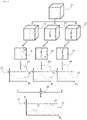
- the objective function and the optimal projection geometry are determined by the figure 2 described in more detail.
- a three-dimensional image dataset 11 is first segmented into a bone structure model 21, a vessel structure model 22 and a third part 23, which contains all the image information of the three-dimensional image dataset 11.
- two-dimensional synthetic forward projections are determined from the segmented parts (31, 32, 33) which are compared with the first and/or second x-ray image and the subtraction image by means of a projection geometry 24 (P i ) and from the comparison for each segmented part (21 , 22, 23) a similarity is determined.
- the maximum value for determining the similarity 45 can be 1, which corresponds to a complete agreement of the synthetic forward projection with the first and/or second x-ray image and the subtraction image.
- the program preferably uses distinctive structural features (34, 35) for the comparison to determine the similarities, for example special bone shapes 34 or distinctive vascular branches 35.
- different similarities (41, 42, 43) of the individual segmented portions (21, 22, 23) can be determined by varying the projection geometry 24 for each additional projection geometry 24 used for all three parts of the target function.
- the projection geometry with the optimal value of the target function is presented as the optimal similarity.
- the optimal similarity can be the global maximum 53 of the objective function 51 determined, it being possible for local extrema 52 in the objective function 51 to be determined in addition to the global optimum 53 .
Landscapes
- Health & Medical Sciences (AREA)
- Engineering & Computer Science (AREA)
- Life Sciences & Earth Sciences (AREA)
- Medical Informatics (AREA)
- Physics & Mathematics (AREA)
- Nuclear Medicine, Radiotherapy & Molecular Imaging (AREA)
- General Health & Medical Sciences (AREA)
- Radiology & Medical Imaging (AREA)
- Public Health (AREA)
- Surgery (AREA)
- Optics & Photonics (AREA)
- Pathology (AREA)
- High Energy & Nuclear Physics (AREA)
- Biomedical Technology (AREA)
- Heart & Thoracic Surgery (AREA)
- Molecular Biology (AREA)
- Biophysics (AREA)
- Animal Behavior & Ethology (AREA)
- Veterinary Medicine (AREA)
- Computer Vision & Pattern Recognition (AREA)
- Theoretical Computer Science (AREA)
- General Physics & Mathematics (AREA)
- Dentistry (AREA)
- Oral & Maxillofacial Surgery (AREA)
- Vascular Medicine (AREA)
- Orthopedic Medicine & Surgery (AREA)
- Epidemiology (AREA)
- Primary Health Care (AREA)
- Computer Graphics (AREA)
- Geometry (AREA)
- Software Systems (AREA)
- Physiology (AREA)
- Quality & Reliability (AREA)
- Apparatus For Radiation Diagnosis (AREA)
- Image Processing (AREA)
Description
- Zahlreiche bekannte medizintechnische Verfahren betreffen die Navigation von Objekten in der Anatomie eines Patienten.
- Bei einer solchen Navigation von Objekten, beispielsweise beim Navigieren von Kathetern innerhalb von Gefäßen, können zur Lokalisation des Objektes röntgenbildgebende Methoden zum Einsatz kommen. Die Gefäße selbst sind dabei zunächst nicht auf den in der Regel kontinuierlich aufgenommenen Röntgenbildern zu erkennen. Aus diesem Grund wird dem Patienten - oft auch wiederholt - ein Kontrastmittel, beispielsweise ein eine Jodverbindung enthaltendes Mittel oder Kohlenstoffdioxid, verabreicht, welches eine Sichtbarmachung der Gefäßstruktur in den Röntgenbildern erlaubt.
- Die gemeinsame und/oder gleichzeitige Darstellung von Objekt, Gefäßstruktur und umgebender Anatomie gestaltet sich sehr schwierig, wie im Folgenden dargestellt wird.
- Für eine permanente Darstellung des Gefäßbaumes - ohne eine erneute Zugabe des Kontrastmittels - kann zunächst ein Durchleuchtungsbild des Gefäßbaumes und der ihn umgebenden Anatomie ohne Kontrastmittel aufgenommen werden (Leerbild). Anschließend wird ein Kontrastmittel injiziert und es werden zu verschiedenen, aufeinanderfolgenden Zeitpunkten Röntgenbilder angefertigt (Füllungsbilder), die die Verteilung des Kontrastmittels im Gefäß zu diesen verschiedenen, aufeinanderfolgenden Zeitpunkten dokumentieren. Die wiederholte Injektion von Kontrastmittel kann unter anderem notwendig sein, da sich das Kontrastmittel, beispielsweise ein eine Jodverbindung enthaltendes Mittel oder Kohlenstoffdioxid, im Blutkreislauf schnell verdünnt, anschließend beispielsweise in die Nieren (Jodverbindung enthaltendes Mittel) bzw. die Lunge (Kohlenstoffdioxid) transportiert und von dort aus dem Patienten wieder ausgeschieden wird. Ferner kann eine wiederholte Kontrastmittelinjektion notwendig sein, um das Gefäß in einer anderen Perspektive darzustellen, die die zu untersuchende Anatomie, beispielsweise eine Stenose, besser darstellt, oder um den Operationsfortschritt zu beurteilen.
- Für die exklusive Darstellung der mit Kontrastmittel gefüllten Gefäßstrukturen wird nun das Leerbild von einem Teil der zu verschiedenen, aufeinanderfolgenden Zeitpunkten aufgenommenen Füllungsbilder subtrahiert (Subtraktionsbilder), so dass nur die mit Kontrastmittel gefüllten Gefäße als zeitliche Sequenz dargestellt werden (digitale Subtraktionsangiographie; DSA). Diese Röntgenbilder können anschließend zu einem Röntgenbild, welches einen mit Kontrastmittel voll ausgefüllten Gefäßbaum darstellt (Gefäßbild), zusammengefasst werden. Dies kann beispielsweise durch ein Minimumsverfahren (im Falle von Jod) oder ein Maximumsverfahren (im Falle von Kohlenstoffdioxid) geschehen, bei dem über den zeitlichen Verlauf der Aufnahme der einzelnen Subtraktionsbilder der jeweils niedrigste bzw. höchste Grauwert für jeden Pixel aus allen Subtraktionsbildern in den jeweiligen Pixel des Gefäßbildes überführt wird. Diese Verfahren sind aus gängigem Stand der Technik bekannt und sollen hier nicht weiter erläutert werden.
- Dieses Subtraktionsbild erlaubt somit die Visualisierung von Gefäßstrukturen samt darin enthaltenen Pathologien wie beispielsweise Stenosen, Aneurysmen oder Einblutungen ins umliegende Gewebe. Die Darstellung der Gefäßstrukturen an sich ermöglicht jedoch noch keine Navigation von Objekten darin zum Zwecke eines medizinischen Eingriffs. Eine weitere Darstellung kann somit mittels eines aus dem Minimumsverfahren/Maximumsverfahren generierten und invertierten Gefäßbildes erzeugt werden. Bei einem sog., aus dem Stand der Technik bekannten, Roadmap-Verfahren kann dieses invertierte Gefäßbild mit einem Live-Röntgenbild aus der Sequenz einer im weiteren Verlauf aufgenommenen DSA überlagert und die Navigation eines Objektes in der Anatomie des Patienten vereinfacht werden. Dieses Verfahren stellt also beispielsweise den zuvor im Gefäßbild extrahierten Gefäßbaum in hellen Graustufen dar, den im Live- Röntgenbild der Sequenz der DSA sichtbaren Katheter aber weiterhin dunkel, sodass dieser während der Bewegung in der Gefäßstruktur erkannt werden kann.
- Wird jedoch die Aufnahmegeometrie verändert, beispielsweise durch ein Verkippen des zur Aufnahme verwendeten Röntgensystems, so passt das zweidimensionale Subtraktionsbild nicht mehr zur neuen Aufnahmegeometrie. Eine Navigation von Objekten ist in der Regel in diesem Fall nicht ohne erneute Kontrastmittelgabe möglich. Eine Kontrastmittelgabe, insbesondere eine wiederholte Kontrastmittelgabe, stellt eine Belastung für den Patienten dar und gilt es weitestgehend zu vermeiden.
- Eine Möglichkeit zur Vermeidung von weiterer Kontrastmittelgabe während eines Eingriffs zur Sichtbarmachung von kontrastarmen Strukturen ist die Verwendung eines vor dem Eingriff aufgenommenen dreidimensionalen Bilddatensatzes, welcher anatomische Informationen bzgl. der Knochen- und Gefäßstrukturen des Untersuchungsbereiches bereitstellt und somit unter Kontrastmittelgabe gewonnen wurde. Um diese im dreidimensionalen Datensatz enthaltenen Strukturen in korrekter Lage auf einem zweidimensionalen Live-Röntgenbild zum Zwecke der Navigation einzublenden, muss zunächst eine synthetische, zweidimensionale Projektion, auch Vorwärtsprojektion genannt, unter einer Projektionsgeometrie berechnet werden, die der Aufnahmegeometrie entspricht. Die Ermittlung der optimalen Projektionsgeometrie stellt dabei ein schwieriges, nicht-konvexes mathematisches Optimierungsproblem dar.
- Die Herausforderung bei einer solchen Vorgehensweise ist, dass die so bestimmte optimale Projektionsgeometrie auch der tatsächlichen Projektionsgeometrie entspricht.
- Bei der Verwendung von kontrastmittelfreien Röntgenbildern für die Ermittlung der optimalen Projektionsgeometrie zwischen einer aus dem dreidimensionalen Bilddatensatz erzeugten Vorwärtsprojektion und den aufgenommenen zweidimensionalen Röntgenbildern weisen insbesondere Knochen einen hohen Bildkontrast in den Röntgenbildern auf. Die alleinige Verwendung von Knochen für die Ermittlung einer Projektionsgeometrie ist hierbei möglich, für eine höhere Genauigkeit der Ähnlichkeit ist jedoch eine zusätzliche Verwendung von Gefäßen bzw. Gefäßstrukturen für die Ähnlichkeit vorteilhaft.
- Ein Verfahren, welches die Ermittlung einer Koordinatentransformation zwischen einem dreidimensionalen Bilddatensatz und zweidimensionalen Röntgenaufnahmen beschreibt, ist in dem Dokument
DE 10 2016 203 857 A1 offenbart. Dabei werden einzelne Registriervorschriften zwischen den Knochen- und Gefäßstrukturen aus den Live-Röntgenbildern und den Vorwärtsprojektionen aus dem dreidimensionalen Bilddatensatz verwendet. - Die Druckschriften
US 2020 / 005 125 8 A1 undUS 2006 / 018 813 9 offenbaren ebenfalls Verfahren für die Registrierung zwischen einem dreidimensionalen und zweidimensionalen Röntgenaufnahmen Bilddatensatz. - Die
US 2011/052026 A1 offenbart ein Verfahren zum Bestimmen eines Winkels eines C-Arm-Bilderfassungssystems für eine Aortenklappenimplantation. Bei dem Verfahren werden eine oder mehrere anatomische Markierungen einer Aortenwurzel in einem 3D-Bild erfasst, und es wird auf der Grundlage der erfassten einen oder mehreren anatomischen Markierungen eine Ebene definiert, die eine Richtung eines Aortenanulus in dem 3D-Bild darstellt. Es wird ein Betrachtungswinkel bestimmt, der senkrecht zu der definierten Ebene ist. - Die
US 2018/0042566 A1 offenbart ein Verfahren zur Klassifizierung eines Videos in der Koronarangiographie, wobei das Verfahren umfasst: Erfassen einer zeitlichen Reihe von angiographischen Bildframes; Entfernen eines oder mehrerer Bildframes aus der zeitlichen Reihe von angiographischen Bildern; Klassifizieren jedes der verbleibenden Bildframes der zeitlichen Reihe von angiographischen Bildern durch einen maschinell erlernten Klassifikator als eine erste anatomische Struktur oder eine zweite anatomische Struktur visualisierend; Kennzeichnen der zeitlichen Reihe von angiographischen Bildframes als die erste anatomische Struktur oder die zweite anatomische Struktur visualisierend, basierend auf den Klassifikationen der verbleibenden Bilder; und Bereitstellen der Kennzeichnung der zeitlichen Reihe für einen Benutzer. - Die Aufgabe der Erfindung ist es, ein verbessertes Verfahren zur Bestimmung einer Projektionsgeometrie zwischen einem dreidimensionalen Bilddatensatz und zweidimensionalen Röntgenbildern bereitzustellen.
- Die Aufgabe der Erfindung wird erfindungsgemäß durch ein Verfahren mit den im Patentanspruch 1 angegebenen Merkmalen gelöst. Vorteilhafte Ausbildungen werden durch die abhängigen Patentansprüche angegeben.
- Das erfindungsgemäße Verfahren zur Verarbeitung eines dreidimensionalen Bilddatensatzes mit zweidimensionalen Röntgenbildern eines Röntgengerätes beinhaltet dabei insbesondere die in Anspruch 1 definierten Schritte.
- Der dreidimensionale Bilddatensatz, welcher anatomische Strukturen eines Untersuchungsbereiches enthält, kann durch eine präoperative Computertomographie- oder Magnetresonanztomographie-Aufnahme angefertigt werden. Die anatomischen Strukturen des dreidimensionalen Bilddatensatzes beinhalten wenigstens Knochen- und Gefäßstrukturen sowie weitere Strukturen beispielsweise Implantatsstrukturen und Hautkanten. Weiterhin kann der dreidimensionale Bilddatensatz auch intra-operativ aufgenommen werden, vorzugsweise unter Verwendung eines intra-operativen Computertomographen oder eines C-Bogen-Röntgengeräts. Ferner besteht die Möglichkeit, den dreidimensionalen Bilddatensatz in eine interne Speichereinheit, beispielsweise einen internen Bilddatenspeicher, oder eine externe Speichereinheit, beispielsweise einen USB-Stick, eine externe Festplatte, oder einen Onlinespeicher, auf welchen das das Verfahren ausführende Röntgengerät Zugriff hat, zu importieren.
- Die Segmentierung des dreidimensionalen Bilddatensatzes kann vor oder nach dem Bereitstellen des dreidimensionalen Bilddatensatzes erfolgen, jeweils manuell, semi-automatisch oder vollautomatisch mittels Bildverarbeitung. Die Segmentierung stellt ein Gefäßstrukturmodell der Gefäßstruktur aus dem dreidimensionalen Bilddatensatz des Untersuchungsbereiches zur Verfügung, ebenso wird mittels der Segmentierung ein dreidimensionales Knochenstrukturmodell der Knochenstruktur aus dem dreidimensionalen Bilddatensatz des Untersuchungsbereiches zur Verfügung gestellt. Solche Modelle können beispielsweise in einer voxelweisen Segmentierung der Bildbereiche bestehen, oder aber als parametrische Repräsentation der zugrundliegenden Strukturen vorliegen. Eine parametrische Repräsentation kann beispielsweise die Beschreibung eines Gefäßes durch einen Spline für die Mittelachse des Gefäßes zzgl. eines Durchmessers an jeder Stelle des Splines sein.
- Das erste und zweite Röntgenbild beschreiben die aktuelle Position des zu untersuchenden Patienten, welcher vorzugsweise auf einer Patientenliege gelagert ist, und werden mittels eines Röntgengeräts, vorzugsweise eines mobilen oder stationären mehrfach motorisch verstellbaren C-Bogen-Röntgengeräts, unter übereinstimmender Aufnahmegeometrie aufgenommen, wobei der Anwender das Röntgengerät so einstellen kann, dass die Aufnahmegeometrie den gewünschten Untersuchungsbereich erfasst. Beispielsweise kann neben der Position des Röntgengeräts die vorgenommene Einstellung den Orbitalwinkel, den Angulationswinkel, den Zoom und/oder die Höhenverstellung betreffen. Es ist vorgesehen, dass beide Röntgenbilder jeweils eine voneinander unterschiedliche Konzentration eines Kontrastmittels enthalten, beispielsweise eine jodhaltige Verbindung oder Kohlenstoffdioxid, wobei die Konzentration des Kontrastmittels für eines der beiden Röntgenbilder auch Null sein kann. Ein solches Vorgehen, wie es insbesondere aus der digitalen Subtraktionsangiographie bekannt ist, ermöglicht es durch die Subtraktion des ersten und des zweiten Röntgenbildes ein Subtraktionsbild zur Verfügung zu stellen, welches nur die Bereiche der Gefäßstruktur enthält, die durch die Hinzugabe des Kontrastmittels sichtbar gemacht werden. In der Regel wird das Kontrastmittel über die Gefäßstruktur des Patienten verabreicht, so dass es primär dessen Gefäßstruktur darstellt, insbesondere die komplette Gefäßstruktur des Patienten. Bei einer geringen Konzentration des verabreichten Kontrastmittels wird insbesondere die Knochenstruktur in den aufgenommenen Röntgenbildern dargestellt. Bei einer verwendeten Konzentration von Null des verabreichten Kontrastmittels erfolgt hauptsächlich die Darstellung der Knochenstrukturen auf dem jeweiligen Röntgenbild, auf den angerfertigten Subtraktionsbildern sind dementsprechend keine Knochenstrukturen mehr vorhanden, da auf den Subtraktionsbildern nur Gefäßstrukturen dargestellt werden.
- Anschließend wird eine Projektionsgeometrie ermittelt, die eine optimale Ähnlichkeit erzielt zwischen einer aus dem dreidimensionalen Bilddatensatz erstellten zweidimensionalen Vorwärtsprojektion, diese entspricht einer zweidimensionalen Projektionsebene und dem ersten und/oder zweiten Röntgenbild sowie dem Subtraktionsbild des Untersuchungsbereiches. Die Bestimmung dieser Projektionsgeometrie kann mittels einer iterativen Vorwärtsprojektion des dreidimensionalen Bilddatensatzes und einem anschließenden algorithmischen Vergleich dieser Vorwärtsprojektion mit dem ersten und/oder zweiten Röntgenbild und dem Subtraktionsbild erfolgen.
- Für diesen algorithmischen Vergleich wird eine dreiteilige Zielfunktion verwendet, wobei die drei Teile der Zielfunktion vorzugsweise additiv miteinander verknüpft sind. Dabei kann eine initiale Projektionsgeometrie, beispielsweise eine vom System vorgegebene Projektionsgeometrie, für die Bestimmung der Projektionsgeometrie verwendet werden. Diese initiale Projektionsgeometrie kann von einer berechnenden Einheit des Röntgengeräts frei gewählt oder von einem Anwender eingestellt werden und stellt die Initialisierung des zu lösenden Optimierungsproblems dar.
- Ein erster Teil der Zielfunktion repräsentiert die Ähnlichkeit des Knochenstrukturmodells zwischen der Vorwärtsprojektion des dreidimensionalen Bilddatensatzes und dem ersten und/oder zweiten Röntgenbild. Bei dem algorithmischen Vergleich können die Vorwärtsprojektion beziehungsweise die im dreidimensionalen Bilddatensatz kontrastmittelhaltigen und segmentierten Gefäße virtuell mit Wasser ersetzt werden, sodass nur Knochenstrukturen in dem synthetischen zweidimensionalen Bild enthalten sind. Vorzugsweise enthält das verwendete Röntgenbild bei dem Vergleich der Knochenmerkmale kein Kontrastmittel und somit hauptsächlich Knochenstrukturen.
- Ein zweiter Teil der Zielfunktion beschreibt eine Ähnlichkeit zwischen der Vorwärtsprojektion aus dem dreidimensionalen Bilddatensatz und dem Subtraktionsbild, welches, wie beispielsweise aus der digitalen Subtraktionsangiographie bekannt, nur Gefäße bzw. Gefäßstrukturen beinhaltet. Vorzugsweise werden in diesem Fall nur die segmentierten, vorwärtsprojizierten Gefäße (Gefäßstrukturmodell) mit dem Subtraktionsbild verglichen. Vorzugsweise wird das erste oder zweite Röntgenbild ohne Kontrastmittel aufgenommen, so dass diese Aufnahme als Leerbild für das Subtraktionsbild verwendet werden kann.
- Es besteht die Möglichkeit, bei der Verwendung unterschiedlicher Arten von Kontrastmitteln entweder die Vorwärtsprojektion oder das Subtraktionsbild einer Inversion des Kontrasts zu unterziehen. Weiterhin können im Falle schlechter Bildqualität die Gefäße in der Vorwärtsprojektion und/oder dem Subtraktionsbild algorithmisch und vollautomatisch aufbereitet werden, um eine Zielfunktion entsprechend dem erfindungsgemäßen Verfahren zu erhalten.
- Ein dritter Teil der Zielfunktion beschreibt eine Ähnlichkeit zwischen der Vorwärtsprojektion aus dem dreidimensionalen Bilddatensatz und des ersten und/oder zweiten Röntgenbildes und hierbei alle Bildinformationen der aufgenommenen Röntgenbilder, welche das erste und zweite Röntgenbild und nicht nur Knochen und/oder Gefäßstrukturen betreffen. Ferner besteht die Möglichkeit, für diesen dritten Teil der Zielfunktion bei der Verwendung von Röntgenbildern, welche mittels Kontrastmittel aufgenommen wurden, die mit Kontrastmittel gefüllten Strukturen durch Wasser zu ersetzen.
- Eine mögliche Form der Zielfunktion F kann eine Linearkombination der drei einzelnen Teile der Zielfunktion (FKnochen-Knochenanteile; FGefäß- Gefäßanteile, FGesamt - alle Anteile) sein:

- Dabei stellen die realen und vorzugsweise positiven Parameter α, β und γ Gewichtungsfaktoren dar, die den relativen Einfluss der einzelnen Anteile der Zielfunktion regulieren können. Die Zielfunktion F kann nun durch ein mathematisches Verfahren durch Variation der Projektionsgeometrie optimiert werden, vorzugsweise durch Anwendung eines iterativen Verfahrens. Während eines jeden Iterationsschrittes kann dabei für alle Teile der Zielfunktion hinweg dieselbe Projektionsgeometrie angenommen werden. Im Anschluss können auf Basis dieser Annahme alle Werte der Teile der Zielfunktion unter Berücksichtigung der Gewichtungsfaktoren aufsummiert werden, um den Wert der Zielfunktion F zu erhalten. In den weiteren Iterationen können anschließend durch das verwendete Optimierungsverfahren weitere Projektionsgeometrien ausgewertet und nach Erreichen eines Abbruch-Kriteriums die Projektionsgeometrie mit dem optimalen Wert der Zielfunktion als die optimale Projektionsgeometrie präsentiert werden.
- Das verwendete Optimierungsverfahren kann dabei aus der Klasse der Gradienten-basierten Verfahren stammen (z.B. konjugierter Gradient, Broyden-Fletcher-Goldfarb-Shanno (BFGS- Verfahren), vorzugsweise jedoch der Klasse der nicht-konvexen Optimierungsverfahren angehören (z.B. Simulated Annealing, genetische Optimierung), oder einer Kombination dieser Verfahren. Die Zielfunktion und somit alle ihre Teile können eine Ähnlichkeit zwischen dem ersten und/oder zweiten Röntgenbild bzw. Subtraktionsbild und der synthetischen Vorwärtsprojektion beschreiben; in diesem Fall handelt es sich bei dem Optimierungsproblem um ein Maximierungsproblem. Gleichermaßen kann die Zielfunktion jedoch auch eine Unähnlichkeit beschreiben; in diesem Fall handelt es sich um ein Minimierungsproblem. Je nach Ausgestaltung der Zielfunktion kann entweder ein Minimierungs- oder Maximierungsverfahren herangezogen werden. Grundsätzlich ist es jedoch auch immer möglich, eine zu maximierende Ähnlichkeit, beispielsweise durch Multiplikation mit "-1", in eine zu minimierende Unähnlichkeit zu transformieren, und umgekehrt. Dies ist insbesondere daher von Bedeutung, da die meisten, in Software-Bibliotheken verfügbaren Optimierungsverfahren als Minimierungsverfahren formuliert und implementiert sind. Im Folgenden soll zur Vereinfachung daher stets von einem Optimierungsproblem die Rede sein.
- Es ist möglich, diese Parameter in Abhängigkeit der Körperregion, in welcher ein Eingriff durchgeführt wird, festzulegen bzw. diese entsprechend zu verändern. Dies kann beispielsweise in einem Programm, vorzugsweise einem Organprogramm, erfolgen. So kann in Knochenstrukturbereichen, welche markante Strukturmerkmale aufweisen, beispielsweise Wirbel mit Wirbelfortsätzen, die Gewichtung von Knochenstrukturähnlichkeiten deutlich höher eingestellt werden als die Gewichtung der Gefäßstrukturähnlichkeit. Gegensätzlich dazu verhalten sich Bereiche, welche weniger markante Knochenstrukturmerkmale aufweisen, beispielsweise der Oberschenkelknochen. In diesem Fall ist eine geringere Gewichtung der Knochenstrukturähnlichkeit und/oder eine entsprechend höhere Gewichtung der Gefäßstrukturen möglich. Die Bestimmung der Gewichtungsfaktoren kann automatisch geschehen, beispielsweise mittels einer Bildanalyse der Röntgenaufnahme und einem Abgleich des Inhalts mit einer hinterlegten Datenbank, welche die Gewichtungsfaktoren bzgl. des Bildinhalts bzw. deren anatomischer Inhalte vorgibt. Ferner können die Koeffizienten auch in einem Organprogramm entsprechend tabelliert gespeichert werden. Weiterhin ist es möglich die Gewichtungsfaktoren mittels eines Benutzereingriffs individuell einzustellen. Ferner besteht die Möglichkeit, dass die Parameter auch den Wert Null annehmen können, beispielsweise durch ein Einstellen des Benutzers, durch Hinterlegung in einem Organprogramm oder durch das erfindungsgemäße Verfahren. Mit dem Nullsetzen eines Gewichtungsfaktors werden Teile der Zielfunktion für deren Bestimmung nicht mehr berücksichtigt.
- Der Wert der Zielfunktion sowie deren Bestandteile können ein Maß für die Qualität der bestimmten Projektionsgeometrie darstellen. Die Zielfunktion kann somit als ein Maß der Ähnlichkeit, beispielsweise eine Deckungsgleichheit, der Vorwärtsprojektion mit dem ersten und/oder zweiten Röntgenbild oder des Subtraktionsbildes sein. Erfüllen die nach Abschluss der Optimierung erhaltenen Werte ein Schwellwertkriterium, welches mit der Zielfunktion verglichen wird, wie es entsprechend in einem Programm, beispielsweise einem Organprogramm, hinterlegt sein kann, ist die ermittelte Projektionsgeometrie als ausreichend korrekt einzustufen.
- In alternativen Ausgestaltungsformen können für den Fall, dass der Wert der Zielfunkton das vorgegebene Schwellwertkriterium erfüllt, die vorwärtsprojizierten Gefäßstrukturen aus dem dreidimensionalen Bilddatensatz mit dem Live-Röntgenbild überlagert werden. Vorzugsweise können in diesem Fall die Gefäße mit oder ohne Kontur, unter Verwendung der bestimmten Projektionsgeometrie auf dem Live- Röntgenbild dargestellt werden. Die Verwendung von solchen Schwellwertkriterien kann vorteilhaft sein, da mittels dieser die Qualität der Projektionsgeometrie sichergestellt werden kann. Somit bietet die Verwendung von Schwellwertkriterien die Möglichkeit, dass bei Nicht-Erfüllung des Schwellwertkriteriums durch den Wert der Zielfunktion ein alternativer Verfahrensweg gewählt werden kann.
- In alternativen Ausgestaltungsformen kann eine wiederkehrende Neuberechnung des ersten und dritten Teils der Zielfunktion (reduzierte Zielfunktion) erfolgen, welche auch ohne Kontrastmittelgabe ständig, also bei Vorliegen eines aktuellen (Live-) Röntgenbildes, zur Verfügung stehen. Wenn kein Kontrastmittel mehr im Untersuchungsbereich vorhanden ist, bleiben diese beiden Teile der Zielfunktion unverändert. Bei der Berechnung dieser beiden Teile der Zielfunktion, basierend auf neuen aufgenommenen Röntgenbildern und der zuvor mittels der erhaltenen Projektionsgeometrie erzielten synthetischen Vorwärtsprojektion, wird der neu berechnete Wert der reduzierten Zielfunktion mit dem vorherigen und gespeicherten Wert der Zielfunktion verglichen. Im Falle, dass der neu berechnete Wert der reduzierten Zielfunktion den alten Wert der Zielfunktion innerhalb einer vorgebbaren Toleranz verfehlt, beispielsweise um einen festzulegenden Faktor, welcher in einem Programm, beispielsweise dem Organprogramm, festgelegt werden kann, wird die Gefäßstruktur bzw. die Gefäßkontur nicht mehr auf dem Live-Röntgenbild dargestellt. Im Fall, dass die neu berechneten Werte der reduzierten Zielfunktion den Schwellwert wieder erfüllen, kann die Gefäßstruktur wieder eingeblendet werden. Ein Vorteil des erfindungsgemäßen Verfahrens kann somit sein, eine kontinuierliche automatisierte Risikoabschätzung dahingehend durchzuführen, dass die Vorwärtsprojektion weiterhin ausreichend der tatsächlichen Projektionsgeometrie entspricht.
- In alternativen Ausgestaltungsformen ist es möglich, dass der Wert der Zielfunktion für ein gewisses Zeitintervall den Schwellwert nicht erfüllt, beispielsweise durch eine Veränderung der Aufnahmegeometrie des Röntgengerätes oder beispielsweise durch eine bekannte Veränderung der Position des Röntgengerätes bzw. Tisches und dadurch des Patienten. Das Röntgengerät kann darüber informieren und dem Anwender eine erneute Bestimmung der Projektionsgeometrie unter erneuter Kontrastmittelgabe oder alternativ das Umschalten in einen alternativen zweidimensionalen Arbeitsablauf anbieten. Die Länge dieses Zeitintervalls, in welchem ein nicht Erfüllen des Schwellwertes erlaubt ist, kann in einem Programm, beispielsweise im Organprogramm, eingestellt werden.
- In alternativen Ausgestaltungsformen kann der Fall auftreten, dass die verglichenen Werte der Zielfunktion dem vorgegebenen Schwellwertkriterium nicht genügen. In diesem Fall kann das Röntgengerät eine Ausgabe auf einem Anzeigegerät, beispielsweise einem Monitor, ausgeben, welche ein Fortlaufen des Verfahrens unterbinden und dem Anwender einen alternativen, zweidimensionalen-Arbeitsablauf anbieten. Diese Vorgehensweise sorgt für eine Risikominimierung.
- In alternativen Ausgestaltungsformen ist es ferner möglich, in einem Programm, beispielsweise einem Organprogramm, dass bei einer Unterschreitung (im Falle einer Maximierung) bzw. Überschreitung (im Falle einer Minimierung) von einem Schwellwert von einem Teil der Zielfunktion, von zwei Schwellwerten von zwei Teilen der Zielfunktion oder von drei Schwellwerten von drei Teilen der Zielfunktion, auf ein zweidimensionales Verfahren umgeschaltet werden kann.
- In einer alternativen Ausgestaltung des Verfahrens ist vorgesehen, in jedem Live-Röntgenbild wenigstens ein Messfeld vorzusehen. Das Messfeld kann unter Benutzereingriff oder durch eine Systemvorgabe derart festgelegt sein, dass das Messfeld eine sich möglicherweise zeitlich verändernde Struktur eng eingrenzt, wobei beispielsweise eine Bewegung des Patienten eine zeitliche verändernde Struktur sein kann. Die Auswertung des Messfeldes erfolgt vorzugsweise durch Addition aller Pixelwerte im Messfeld und Überwachung des Summenwertes in einer Folge von Live-Bildern. Bei einer örtlichen Veränderung der eingegrenzten Struktur im Messfeld ändert sich der Summerwert der Pixelwerte gegenüber dem Summenwert des vorherigen Live-Röntgenbildes. Es ist vorgesehen, den Summenwert durch Schwellwertsetzung zu überwachen.
- Der Schwellwert kann vorzugsweise als Bruchteil des Summenwertes des vorherigen Live-Röntgenbildes festgelegt sein. Bei einer überschwelligen Veränderung des Summenwertes gegenüber dem vorherigen Live-Röntgenbild wird eine überschwellige Verlagerung der eingegrenzten Struktur angenommen
- In einer alternativen Ausgestaltung wird anstatt des einen Subtraktionsbildes eine komplette digitale Subtraktionsangiografie angefertigt, welche nicht nur einen Teil, sondern die komplette Gefäßstruktur darstellt. In einer alternativen Ausgestaltung kann ergänzend zur DSA in bekannter Weise ein Minimums- bzw. Maximumsverfahren durchgeführt werden. Bei solchen Verfahren wird über den zeitlichen Verlauf der Aufnahme der einzelnen Subtraktionsbilder der DSA der jeweils niedrigste (Minimumsverfahren) bzw. höchste (Maximumsverfahren) Grauwert für jeden Pixel aus allen Subtraktionsbildern in den jeweiligen Pixel eines Gefäßbildes überführt. Für den weiteren Verfahrensverlauf wird dann anstatt der ersten oder zweiten Aufnahme das mittels des Minimums bzw. Maximumsverfahren erzeugte Gefäßbild anstelle des Subtraktionsbildes genutzt.
- In den nachfolgenden Ausführungsbeispielen wird die Erfindung genauer erläutert.
-
Fig. 1 zeigt einen beispielsweisen Verfahrensablauf des erfindungsgemäßen Verfahrens. -
Fig. 2 zeigt in einer beispielhaften grafischen Darstellung die Bestimmung der optimalen Projektionsgeometrie zwischen einem aufgenommen dreidimensionalen Bilddatensatz und dem ersten und/oder zweiten Röntgenbild und dem Subtraktionsbild. - Das Verfahren wird mit Bezug zur
Figur 1 undFigur 2 näher erläutert. - Während des Verfahrens kann diesem ein kontinuierliches Röntgenbild (Live-Röntgenbild) zur Verfügung gestellt werden, mit welchem zweidimensionale Gefäßstrukturen, welche aus einem zuvor aufgenommenen dreidimensionalen Bilddatensatz durch Projektion erhalten wurden, überlagert werden, um dem Anwender eine Darstellungsmöglichkeit der Gefäßstrukturen auf einem Live-Röntgenbild zur Verfügung zu stellen.
- Im Verfahrensschritt V1 wird zunächst der dreidimensionale Bilddatensatz aufgenommen, beispielsweise mittels eines Computertomographen oder eines Magnetresonanztomographen. Dieser dreidimensionale Bilddatensatz umfasst dabei die Knochenstruktur und die Gefäßstruktur eines Untersuchungsbereiches. Der dreidimensionale Bilddatensatz kann präoperativ oder intraoperativ aufgenommen werden.
- In einem Verfahrensschritt V2 wird anschließend der dreidimensionale Bilddatensatz in Knochenstruktur und Gefäßstruktur segmentiert, dies kann ebenfalls direkt nach der präoperativen Aufnahme oder vor dem geplanten Eingriff geschehen.
- Nach der Positionierung des Patienten bezüglich des (C-Bogen-)Röntgengerätes wird in einem Verfahrensschritt V3 eine erste Röntgenaufnahme des Patienten angefertigt, dabei kann dem Patienten ein Kontrastmittel injiziert werden. Es empfiehlt sich jedoch, insbesondere die erste Röntgenaufnahme ohne ein Kontrastmittel anzufertigen, so dass die erste Röntgenaufnahme hauptsächlich nur die Knochenstruktur zeigt, samt umgebender, schwach sichtbarer Weichteilstrukturen.
- In einem Verfahrensschritt V4 wird weiterhin eine zweite Röntgenaufnahme des Untersuchungsbereiches angefertigt, bei welcher dem Patienten ein Kontrastmittel injiziert wurde, so dass Teile seiner Gefäßstruktur sichtbar gemacht werden. Im Verfahrensschritt V4 kann ebenfalls eine digitale Subtraktionsangiografie durchgeführt werden. Nach einer digitalen Subtraktionsangiografie kann im Verfahrensschritt V5 ein darauffolgendes Minimums- bzw. Maximumsverfahren angewendet werden, bei welchem über den zeitlichen Verlauf der Aufnahme der digitalen Subtraktionsangiografie der jeweils niedrigste bzw. höchste Grauwert für jeden Pixel aus allen Subtraktionsbildern in den jeweiligen Pixel eines Gefäßbildes überführt wird. Für den weiteren Verfahrensverlauf wird das erzeugte Gefäßbild genutzt, welches die komplette Gefäßstruktur darstellt.
- Der darauffolgende Verfahrensschritt V6 umfasst die Ermittlung der optimalen Projektionsgeometrie zwischen einer Vorwärtsprojektion des dreidimensionalen Bilddatensatzes und des ersten Röntgenbildes. Die Vorwärtsprojektion ist ein aus dem dreidimensionalen Bilddatensatz synthetisiertes zweidimensionales Röntgenbild. Es besteht ferner die Möglichkeit anstelle des ersten Röntgenbildes das zweite Röntgenbild zu verwenden.
- In einem Verfahrensschritt V6-1 kann der erste Teil der Zielfunktion eine Ähnlichkeit der Knochenstruktur zwischen der Vorwärtsprojektion des dreidimensionalen Bilddatensatzes und des ersten und/oder zweiten Röntgenbildes bestimmt werden. Vorzugsweise wird in Verfahrensschritt V6-1 das Röntgenbild verwendet, bei welcher hauptsächlich die Knochenstrukturen dargestellt sind.
- Für den Verfahrensschritt V6-1 kann ein algorithmischer Vergleich zwischen der Vorwärtsprojektion und des ersten Röntgenbildes verwendet werden. Bei diesem algorithmischen Vergleich kann die Ähnlichkeit aus einer Vorwärtsprojektion und des ersten Röntgenbildes maximiert werden, vorzugsweise unter Variation der Geometrie unter welcher die Vorwärtsprojektion erstellt wird, beispielsweise unter Verwendung von bis zu drei Translationen und bis zu drei Rotationen der Projektionsgeometrie. Für die Bestimmung der Ähnlichkeit der Knochenstruktur empfiehlt es sich vorzugsweise die in der Vorwärtsprojektion beziehungsweise die im dreidimensionalen Bilddatensatz kontrastmittelhaltigen und segmentierten Gefäßstrukturen virtuell mit Wasser zu ersetzen, so dass nur Knochenstrukturen in der Vorwärtsprojektion enthalten sind. Es empfiehlt sich bei der Bestimmung der Ähnlichkeit der Knochenstrukturen, dass das verwendete erste Röntgenbild vorzugsweise ebenfalls kein Kontrastmittel aufweist und somit nur Knochenstrukturen darstellt.
- Im Verfahrensschritt V6-2 wird der zweite Teil der Zielfunktion bestimmt. Die Gefäßstrukturen des Gefäßbildes aus Verfahrensschritt V5 werden mit der aus dem dreidimensionalen Bilddatensatz erzeugten Vorwärtsprojektion verglichen. Die Ähnlichkeit der Gefäßstruktur zwischen der Vorwärtsprojektion des dreidimensionalen Bilddatensatzes und dem ersten und/oder zweiten Röntgenbild und des Subtraktionsbildes kann ebenfalls mittels eines algorithmischen Vergleichs unter Variation der Projektionsgeometrie berechnet werden Es empfiehlt sich im Fall der Bestimmung der Ähnlichkeit der Gefäßstruktur vorzugsweise nur die segmentierten Gefäße in der Vorwärtsprojektion mit dem Subtraktionsbild zu vergleichen.
- Im Verfahrensschritt V6-3 wird eine Ähnlichkeit basierend auf allen Bildinformationen zwischen der Vorwärtsprojektion des dreidimensionalen Bilddatensatzes und der ersten und/oder zweiten Röntgenaufnahme ermittelt. Bei der Bestimmung des dritten Teils der Zielfunktion werden alle Bildinformationen der ersten und/oder zweiten Röntgenaufnahme verwendet. Für den Verfahrensschritt können beispielsweise Gewebe-zu-Luft-Übergänge, welche markante Strukturmerkmale darstellen können, verwendet werden. Die Verfahrensschritte V6-1, V6-2 und V6-3 können in ihrer Reihenfolge vertauscht werden, ohne den Verfahrensablauf zu beeinträchtigen.
- Die Optimierung der Zielfunktion kann durch Anwendung eines iterativen Verfahrens durchgeführt werden. Während eines jeden Iterationsschrittes wird dabei für die Verfahrensschritte V6-1 - V6-3 (alle Teile der Zielfunktion) hinweg dieselbe Projektionsgeometrie angenommen. Im Anschluss werden auf Basis dieser Annahme alle Werte der Teile der Zielfunktion unter Berücksichtigung der Gewichtung der Teile der Zielfunktion aufsummiert, um den Wert der Zielfunktion für eine Projektionsgeometrie zu erhalten. In den weiteren Iterationen werden dann durch das verwendete Optimierungsverfahren weitere Projektionsgeometrien ausgewertet und nach Erreichen eines Abbruch-Kriteriums, beispielsweise das Erreichen der maximalen Iterationsschritte die Projektionsgeometrie mit dem optimalen Wert der Zielfunktion als die optimale Ähnlichkeit präsentiert.
- Im Verfahrensschritt V7 ist es vorgesehen, im Falle einer erfolgreichen Bestimmung der Projektionsgeometrie das zweidimensionale Live-Röntgenbild mit den unter der optimalen Projektionsgeometrie vorwärtsprojizierten Gefäßstrukturen in der Ebene des Röntgenbildes zu überlagern. Beispielsweise können Gefäßstrukturen mit oder ohne Kontur oder nur die Kontur, unter Verwendung der Vorwärtsprojektion des Gefäßstrukturmodells bei der optimalen Projektionsgeometrie auf einem Anzeigegerät mit dem Live-Röntgenbild überlagert dargestellt werden.
- Es ist möglich, dass sich die Lage des Untersuchungsbereiches auch während des Eingriffs ändert, beispielsweise durch eine Änderung der Aufnahmegeometrie des Röntgengerätes oder durch eine Verstellung der Tischposition. Diese Änderungen können ohne erneute Kontrastmittelgabe eine weitere Anwendung des Verfahrens ermöglichen, wobei die Möglichkeit besteht, auch ohne eine erneute Bestimmung der optimalen Projektionsgeometrie mit dem erfindungsgemäßen Verfahren fortzufahren, nur durch eine Transformation der vor der Änderung der Aufnahmegeometrie ermittelten Projektionsgeometrie. In dem Fall, dass sich die Aufnahmegeometrie ändert, können Encoder, dabei handelt es sich um Positions- und Winkelgeber des Röntgengerätes oder des Tisches ausgewertet werden und diese Informationen mit der zuvor bestimmten optimalen Projektionsgeometrie verrechnet werden.
- Gemäß dem Fall, dass der neue Wert den hinterlegten Schwellwert überschreitet (im Falle eines Minimierungsproblems) bzw. unterschreitet (im Falle eines Maximierungsproblems), beispielsweise um einen festzulegenden Faktor, welcher in einem Programm, beispielsweise dem Organprogramm, festgelegt werden kann, kann die Gefäßstruktur bzw. die Gefäßkontur nicht mehr auf dem Live-Röntgenbild dargestellt werden. Im Fall, dass die neu berechneten Werte den Schwellwert wieder unterschreiten, kann die Gefäßstruktur wieder eingeblendet werden. Letzteres kann auch der Fall sein bei einem kurzfristigen Überschreiten des Schwellwertes, beispielsweise durch eine Bewegung des Operationstisches, durch eine Bewegung des Röntgengerätes oder eine dem Röntgengerät nicht angekündigte Kontrastmittelgabe. Werden die Werte innerhalb eines vordefinierten Zeitintervalls, welches in einem Programm, beispielsweise im Organprogramm eingestellt werden kann, nicht mehr unter- bzw. überschritten, kann das Röntgengerät darüber informieren und dem Anwender eine erneute Bestimmung der Projektionsgeometrie unter erneuter Kontrastmittelgabe oder alternativ das Umschalten in einen alternativen zweidimensionalen Arbeitsablauf anbieten.
- Ein Umschalten auf eine alternative zweidimensionale Darstellung ist in
Fig. 1 als Verfahrensschritt V8 dargestellt. In dem Fall, dass die verglichenen Werte die entsprechenden Schwellwerte nicht erfüllen, kann das Röntgengerät darüber informieren, beispielsweise durch anzeigen einer Meldung auf dem Anzeigegerät. Der Anwender kann nun das Umschalten auf den 2D-Arbeitsablauf auswählen, auch dies entspricht Verfahrensschritt V8. - Die Bestimmung der Zielfunktion und der optimalen Projektionsgeometrie wird durch die
Figur 2 näher beschrieben. - In
Figur 2 wird zunächst ein dreidimensionaler Bilddatensatz 11 in ein Knochenstrukturmodell 21, in ein Gefäßstrukturmodell 22 und in einen dritten Teil 23, welcher alle Bildinformationen des dreidimensionalen Bilddatensatzes 11 enthält, segmentiert. Anschließend werden jeweils aus den segmentierten Anteilen zweidimensionale synthetische Vorwärtsprojektionen ermittelt (31, 32, 33) welche mittels einer Projektionsgeometrie 24 (Pi) mit dem ersten und/oder zweiten Röntgenbild und dem Subtraktionsbild verglichen werden und aus dem Vergleich für jeden segmentierten Anteil (21, 22, 23) eine Ähnlichkeit bestimmt wird. Der maximale Wert für die Bestimmung der Ähnlichkeit 45 kann dabei 1 betragen, dies entspricht einer kompletten Übereinstimmung der synthetischen Vorwärtsprojektion mit dem ersten und/oder zweiten Röntgenbild und dem Subtraktionsbild. Vorzugsweise verwendet das Programm für den Vergleich zur Bestimmung der Ähnlichkeiten markante Strukturmerkmale (34, 35), beispielsweise spezielle Knochenformen 34 oder markante Gefäßverzweigungen 35. - Eine anschließende Summation 44 der Ähnlichkeiten der einzelnen segmentierten Anteile (21, 22, 23), wobei die Ähnlichkeiten der einzelnen segmentierten Anteile (21, 22, 23) jeweils mittels eines Koeffizienten gewichtet sein können, ergibt einen Wert der Zielfunktion 51. Durch weitere Iterationsschritte kann unter Variation der Projektionsgeometrie 24 für jede weitere verwendete Projektionsgeometrie 24 alle drei Teile der Zielfunktion verschiedene Ähnlichkeiten (41, 42, 43) der einzelnen segmentierten Anteile (21, 22, 23) ermittelt werden.
- In den weiteren Iterationen werden dann durch das verwendete Optimierungsverfahren weitere Projektionsgeometrien ausgewertet und nach Erreichen eines Abbruch-Kriteriums, beispielsweise das Erreichen eines vorgegebenen Schwellwertes der Zielfunktion, die Projektionsgeometrie mit dem optimalen Wert der Zielfunktion als die optimale Ähnlichkeit präsentiert. Die optimale Ähnlichkeit kann das globale Maximum 53 der ermittelten Zielfunktion 51 sein, wobei neben dem globalen Optimum 53 auch lokale Extrema 52 in der Zielfunktion 51 ermittelt werden können.
Claims (12)
- Computer-implementiertes Verfahren zur Verarbeitung eines dreidimensionalen Bilddatensatzes (11) mit zweidimensionalen Röntgenaufnahmen eines Röntgengerätes, beinhaltend die Schritte:• Bereitstellen eines dreidimensionalen Bilddatensatzes (11) wenigstens eines Untersuchungsbereiches, in welchem anatomische Strukturen vorliegen,• Segmentieren des dreidimensionalen Bilddatensatzes (11) für eine Zurverfügungstellung eines eine Gefäßstruktur beschreibenden dreidimensionalen Gefäßstrukturmodells (22) und eines eine Knochenstruktur beschreibenden dreidimensionalen Knochenstrukturmodells (21),• Aufnehmen, mittels des Röntgengeräts, eines ersten zweidimensionalen Röntgenbildes, welches wenigstens teilweise die Knochenstruktur und wenigstens teilweise die Gefäßstruktur enthält, unter einer Aufnahmegeometrie und dem Vorliegen einer ersten Kontrastmittelkonzentration,• Aufnehmen, mittels des Röntgengeräts, eines zweiten zweidimensionalen Röntgenbildes des Untersuchungsbereiches, welches eine zum ersten Röntgenbild unterschiedliche zweite Kontrastmittelkonzentration enthält, wobei die Aufnahme des zweiten Röntgenbildes unter der gleichen Aufnahmegeometrie wie die Aufnahme des ersten Röntgenbildes erfolgt,• Subtraktion des ersten und des zweiten Röntgenbildes zur Erzeugung und Zurverfügungstellung eines Subtraktionsbildes, wobei das Subtraktionsbild eine Gefäßstruktur enthält,• Ermitteln einer optimalen Projektionsgeometrie (24) unter Verwendung einer dreiteiligen Zielfunktion (51),▪ wobei ein erster Teil der Zielfunktion (51) eine Ähnlichkeit zwischen einer Vorwärtsprojektion (31; 32; 33) des Knochenstrukturmodells (21) des dreidimensionalen Bilddatensatzes (11) und der Knochenstruktur in dem ersten und/oder zweiten Röntgenbild unter Variation einer angenommenen Projektionsgeometrie (Pi) darstellt,▪ wobei ein zweiter Teil der Zielfunktion (51) eine Ähnlichkeit zwischen der Vorwärtsprojektion (31; 32; 33) des Gefäßstrukturmodells (22) des dreidimensionalen Bilddatensatzes (11) und der Gefäßstruktur des Subtraktionsbildes unter Variation der angenommenen Projektionsgeometrie (24) darstellt,▪ und wobei ein dritter Teil (23) der Zielfunktion (51) eine Ähnlichkeit zwischen allen Bildinformationen der Vorwärtsprojektion (31; 32; 33) des dreidimensionalen Bilddatensatzes (11) und allen Bildinformationen des ersten und/oder zweiten Röntgenbildes unter Variation der angenommenen Projektionsgeometrie (24) darstellt; wobei• die optimale Projektionsgeometrie (24) aus einer Minimierung oder Maximierung (53) der Zielfunktion (51) hervorgeht.
- Verfahren nach Anspruch 1, dadurch gekennzeichnet, dass die Zielfunktion (51) und/oder Teile der Zielfunktionen (51) mit einem vorgebbaren Schwellwertkriterium verglichen werden.
- Verfahren nach Anspruch 2, dadurch gekennzeichnet, dass bei Verfehlen des Schwellwertkriteriums der Zielfunktion (51) das Verfahren abgebrochen und einem Anwender das Umschalten auf ein alternatives zweidimensionales Verfahren angeboten wird.
- Verfahren nach einem der vorhergehenden Ansprüche, dadurch gekennzeichnet, dass zur Ermittlung der optimalen Projektionsgeometrie (24) die drei Teile der Zielfunktion (51) unterschiedlich gewichtet werden.
- Verfahren nach einem der vorhergehenden Ansprüche, dadurch gekennzeichnet, dass anstatt einer zweiten zweidimensionalen Röntgenaufnahme des Untersuchungsbereiches eine digitale Subtraktionsangiografie erzeugt und verwendet wird.
- Verfahren nach Anspruch 5, dadurch gekennzeichnet, dass die digitale Subtraktionsangiografie durch ein Minimums- oder Maximumsverfahren zusammengefasst wird.
- Verfahren nach einem der vorhergehenden Ansprüche, dadurch gekennzeichnet, dass das Röntgengerät eine C-Bogen-Röntgeneinrichtung ist.
- Verfahren nach einem der vorhergehenden Ansprüche, dadurch gekennzeichnet, dass der dreidimensionale Bilddatensatz mittels eines Computertomographen, eines Magnetresonanztomographen oder eines C-Bogen-Röntgengeräts aufgenommen wird.
- Verfahren nach einem der vorhergehenden Ansprüche, dadurch gekennzeichnet, dass der dreidimensionale Bilddatensatz vor dem erfindungsgemäßen Verfahren für die Zurverfügungstellung einer dreidimensionalen Gefäßstruktur und einer dreidimensionalen Knochenstruktur segmentiert wurde.
- Verfahren nach einem der vorhergehenden Ansprüche, dadurch gekennzeichnet, dass die Überlagerung einer Vorwärtsprojektion (31; 32; 33) unter der optimalen Projektionsgeometrie (24) mit einem Live-Röntgenbild nicht weiter auf einem Bildschirm angezeigt wird, wenn eine Bewegung des Röntgengerätes, eine Änderung der Aufnahmegeometrie eines Live-Röntgenbildes oder/und eine Verlagerung eines Patienten auf einer Patientenliege festgestellt wurden.
- Verfahren nach einem der vorhergehenden Ansprüche, dadurch gekennzeichnet, dass in einem Live-Röntgenbild wenigstens ein Messfeld festgelegt ist, dass das Messfeld eine sich möglicherweise zeitlich verändernde Struktur eng eingrenzt und dass für das Live-Röntgenbild eine Auswertung derart erfolgt, dass ein durch Addition aller Pixelwerte im Messfeld erhaltener Summenwert überwacht wird und bei einer vorgegebenen prozentualen Veränderung des Summenwertes gegenüber dem Summenwert eines vorherigen Live-Röntgenbildes eine Überlagerung einer Vorwärtsprojektion unter der optimalen Projektionsgeometrie (24) mit dem Live-Röntgenbild am Bildschirm nicht weiter erfolgt.
- Verfahren nach einem der vorhergehenden Ansprüche, dadurch gekennzeichnet, dass die Gefäßstruktur mit oder ohne eine Kontur oder nur eine Kontur unter Verwendung der Vorwärtsprojektion (31; 32; 33) des Gefäßstrukturmodells 22 bei der optimalen Projektionsgeometrie (24) auf einem Anzeigegerät mit einem Live-Röntgenbild überlagert dargestellt werden.
Applications Claiming Priority (1)
| Application Number | Priority Date | Filing Date | Title |
|---|---|---|---|
| DE102020001314.7A DE102020001314B3 (de) | 2020-02-27 | 2020-02-27 | Verfahren zur Überlagerung projektiver Abbildungen dreidimensionaler Strukturen mit einem zweidimensionalen Röntgenbild |
Publications (2)
| Publication Number | Publication Date |
|---|---|
| EP3871610A1 EP3871610A1 (de) | 2021-09-01 |
| EP3871610B1 true EP3871610B1 (de) | 2022-07-20 |
Family
ID=76310744
Family Applications (1)
| Application Number | Title | Priority Date | Filing Date |
|---|---|---|---|
| EP21159054.2A Active EP3871610B1 (de) | 2020-02-27 | 2021-02-24 | Verfahren zur überlagerung projektiver abbildungen dreidimensionaler strukturen mit einem zweidimensionalen röntgenbild |
Country Status (4)
| Country | Link |
|---|---|
| US (1) | US11490868B2 (de) |
| EP (1) | EP3871610B1 (de) |
| DE (1) | DE102020001314B3 (de) |
| ES (1) | ES2927559T3 (de) |
Family Cites Families (10)
| Publication number | Priority date | Publication date | Assignee | Title |
|---|---|---|---|---|
| US7787683B2 (en) * | 2004-12-20 | 2010-08-31 | Siemens Medical Solutions Usa, Inc. | Tree structure based 2D to 3D registration |
| US20110052026A1 (en) * | 2009-08-28 | 2011-03-03 | Siemens Corporation | Method and Apparatus for Determining Angulation of C-Arm Image Acquisition System for Aortic Valve Implantation |
| US10621738B2 (en) * | 2011-03-16 | 2020-04-14 | Siemens Healthcare Gmbh | 2D/3D registration for abdominal aortic aneurysm intervention |
| US8588501B2 (en) * | 2011-07-29 | 2013-11-19 | Siemens Aktiengesellschaft | Automatic pose initialization for accurate 2-D/3-D registration applied to abdominal aortic aneurysm endovascular repair |
| DE102016203857B4 (de) | 2016-03-09 | 2021-05-12 | Siemens Healthcare Gmbh | Verfahren zur Erfassung und Verarbeitung von Bilddaten eines Untersuchungsobjekts |
| US10667776B2 (en) * | 2016-08-11 | 2020-06-02 | Siemens Healthcare Gmbh | Classifying views of an angiographic medical imaging system |
| US11160610B2 (en) * | 2017-02-07 | 2021-11-02 | Intellijoint Surgical Inc. | Systems and methods for soft tissue navigation |
| EP3441003B1 (de) * | 2017-08-08 | 2020-07-22 | Siemens Healthcare GmbH | Verfahren zur ausführung einer digitalen substraktionsangiographie, hybridbildgebungsvorrichtung, computerprogramm und elektronisch lesbares speichermedium |
| WO2019051464A1 (en) * | 2017-09-11 | 2019-03-14 | Lang Philipp K | INCREASED REALITY DISPLAY FOR VASCULAR AND OTHER INTERVENTIONS, COMPENSATION FOR CARDIAC AND RESPIRATORY MOVEMENT |
| EP3890642A2 (de) * | 2018-12-03 | 2021-10-13 | 3mensio Medical Imaging B.V. | Verfahren, vorrichtung und system zur prozedurplanung von intrakavitalen sonden |
-
2020
- 2020-02-27 DE DE102020001314.7A patent/DE102020001314B3/de active Active
-
2021
- 2021-02-23 US US17/183,192 patent/US11490868B2/en active Active
- 2021-02-24 ES ES21159054T patent/ES2927559T3/es active Active
- 2021-02-24 EP EP21159054.2A patent/EP3871610B1/de active Active
Also Published As
| Publication number | Publication date |
|---|---|
| DE102020001314B3 (de) | 2021-07-01 |
| US11490868B2 (en) | 2022-11-08 |
| US20210267566A1 (en) | 2021-09-02 |
| ES2927559T3 (es) | 2022-11-08 |
| EP3871610A1 (de) | 2021-09-01 |
Similar Documents
| Publication | Publication Date | Title |
|---|---|---|
| EP4129189B1 (de) | Verfahren zum betreiben eines medizinischen bildgebungsgeräts zur lagerichtigen darstellung von nicht-anatomischen strukturen während einer bildgebenden untersuchung und vorrichtung hierfür | |
| DE102006045423B4 (de) | 07.09.07Verfahren zur Nachbearbeitung eines dreidimensionalen Bilddatensatzes einer Gefäßstruktur | |
| EP3185215B1 (de) | Automatisierte ermittlung von konturen auf basis einer iterativen rekonstruktion | |
| DE102005030646B4 (de) | Verfahren zur Kontur-Visualisierung von zumindest einer interessierenden Region in 2D-Durchleuchtungsbildern | |
| DE102019201079B4 (de) | Verfahren und bildgebendes Gerät zum Erzeugen eines bewegungskompensierten Bildes, Computerprogramm und Speichermedium | |
| DE10317367B4 (de) | Verfahren zur Durchführung der digitalen Subtraktionsangiographie unter Verwendung nativer Volumendatensätze | |
| DE10047314A1 (de) | Verfahren zur Erzielung eines virtuellen Kontrastmittels für erweiterte Angioskopie | |
| DE102021210879A1 (de) | Bereitstellen eines Vergleichsdatensatzes | |
| DE102006046735A1 (de) | Vorrichtung zur Fusion eines 2D-Durchleuchtungsbildes mit einem Bild aus einem 3D-Bilddatensatz | |
| DE102009015386A1 (de) | Verfahren und Vorrichtung zur Erzeugung eines funktionellen Datensatzes eines perfundierten Bereichs des menschlichen oder tierischen Körpers | |
| DE102020201928A1 (de) | Verfahren zur Deformationskorrektur | |
| DE102011017710B4 (de) | Verfahren zum Bereitstellen eines 3D-Röntgenbilddatensatzes zu einem sich bewegenden Objekt mit stark absorbierendem Material | |
| DE102006003126A1 (de) | Verfahren und Vorrichtung zum Visualisieren von 3D-Objekten | |
| DE102013202313A1 (de) | Verfahren und Vorrichtung zur Korrektur von Bewegungsartefakten bei einem computertomographischen Bild | |
| EP2242023A1 (de) | Verfahren zur bewegungskompensierten Rekonstruktion eines dreidimensionalen endgültigen Bilddatensatzes | |
| DE102006049865B4 (de) | Auswertungsverfahren für Daten eines Untersuchungsobjekts unter Korrelierung eines Volumendatensatzes mit einer Anzahl von Durchleuchtungsbildern | |
| DE102009031139B4 (de) | Ermittlungsverfahren für eine Neu-Initialisierung einer zeitlichen Sequenz von Durchleuchtungsbildern (B(t)) eines Untersuchungsbereichs eines Untersuchungsobjekts und zugehörige Gegenstände | |
| DE102009033452B4 (de) | Verfahren zur Bereitstellung eines segmentierten Volumendatensatzes für eine virtuelle Koloskopie sowie zugehörige Gegenstände | |
| EP2634748A1 (de) | Bilddatenbestimmungsverfahren | |
| DE102016215970B3 (de) | Verfahren zum Betreiben eines Röntgengerätes sowie Röntgengerät für ein Erstellen einer dreidimensionalen Angiographie | |
| DE10210644B4 (de) | Verfahren zum Erstellen einer Sequenz | |
| DE102007051479B4 (de) | Verfahren und Vorrichtung zur Darstellung von Bilddaten mehrerer Bilddatensätze während einer medizinischen Intervention | |
| DE102020001314B3 (de) | Verfahren zur Überlagerung projektiver Abbildungen dreidimensionaler Strukturen mit einem zweidimensionalen Röntgenbild | |
| DE102006056679B4 (de) | Verfahren und Vorrichtung zum Visualisieren von 3D-Objekten, insbesondere in Echtzeit | |
| DE102023202451A1 (de) | Bereitstellen eines Ergebnisdatensatzes |
Legal Events
| Date | Code | Title | Description |
|---|---|---|---|
| PUAI | Public reference made under article 153(3) epc to a published international application that has entered the european phase |
Free format text: ORIGINAL CODE: 0009012 |
|
| STAA | Information on the status of an ep patent application or granted ep patent |
Free format text: STATUS: REQUEST FOR EXAMINATION WAS MADE |
|
| STAA | Information on the status of an ep patent application or granted ep patent |
Free format text: STATUS: EXAMINATION IS IN PROGRESS |
|
| 17P | Request for examination filed |
Effective date: 20210224 |
|
| AK | Designated contracting states |
Kind code of ref document: A1 Designated state(s): AL AT BE BG CH CY CZ DE DK EE ES FI FR GB GR HR HU IE IS IT LI LT LU LV MC MK MT NL NO PL PT RO RS SE SI SK SM TR |
|
| 17Q | First examination report despatched |
Effective date: 20210810 |
|
| GRAP | Despatch of communication of intention to grant a patent |
Free format text: ORIGINAL CODE: EPIDOSNIGR1 |
|
| STAA | Information on the status of an ep patent application or granted ep patent |
Free format text: STATUS: GRANT OF PATENT IS INTENDED |
|
| INTG | Intention to grant announced |
Effective date: 20220202 |
|
| RBV | Designated contracting states (corrected) |
Designated state(s): AL AT BE BG CH CY CZ DE DK EE ES FI FR GB GR HR HU IE IS IT LI LT LU LV MC MK MT NL NO PL PT RO RS SE SI SK SM TR |
|
| GRAS | Grant fee paid |
Free format text: ORIGINAL CODE: EPIDOSNIGR3 |
|
| GRAA | (expected) grant |
Free format text: ORIGINAL CODE: 0009210 |
|
| STAA | Information on the status of an ep patent application or granted ep patent |
Free format text: STATUS: THE PATENT HAS BEEN GRANTED |
|
| AK | Designated contracting states |
Kind code of ref document: B1 Designated state(s): AL AT BE BG CH CY CZ DE DK EE ES FI FR GB GR HR HU IE IS IT LI LT LU LV MC MK MT NL NO PL PT RO RS SE SI SK SM TR |
|
| REG | Reference to a national code |
Ref country code: CH Ref legal event code: EP |
|
| REG | Reference to a national code |
Ref country code: DE Ref legal event code: R096 Ref document number: 502021000077 Country of ref document: DE |
|
| REG | Reference to a national code |
Ref country code: AT Ref legal event code: REF Ref document number: 1505037 Country of ref document: AT Kind code of ref document: T Effective date: 20220815 |
|
| REG | Reference to a national code |
Ref country code: IE Ref legal event code: FG4D Free format text: LANGUAGE OF EP DOCUMENT: GERMAN |
|
| REG | Reference to a national code |
Ref country code: NL Ref legal event code: FP |
|
| REG | Reference to a national code |
Ref country code: ES Ref legal event code: FG2A Ref document number: 2927559 Country of ref document: ES Kind code of ref document: T3 Effective date: 20221108 |
|
| REG | Reference to a national code |
Ref country code: LT Ref legal event code: MG9D |
|
| PG25 | Lapsed in a contracting state [announced via postgrant information from national office to epo] |
Ref country code: SE Free format text: LAPSE BECAUSE OF FAILURE TO SUBMIT A TRANSLATION OF THE DESCRIPTION OR TO PAY THE FEE WITHIN THE PRESCRIBED TIME-LIMIT Effective date: 20220720 Ref country code: RS Free format text: LAPSE BECAUSE OF FAILURE TO SUBMIT A TRANSLATION OF THE DESCRIPTION OR TO PAY THE FEE WITHIN THE PRESCRIBED TIME-LIMIT Effective date: 20220720 Ref country code: PT Free format text: LAPSE BECAUSE OF FAILURE TO SUBMIT A TRANSLATION OF THE DESCRIPTION OR TO PAY THE FEE WITHIN THE PRESCRIBED TIME-LIMIT Effective date: 20221121 Ref country code: NO Free format text: LAPSE BECAUSE OF FAILURE TO SUBMIT A TRANSLATION OF THE DESCRIPTION OR TO PAY THE FEE WITHIN THE PRESCRIBED TIME-LIMIT Effective date: 20221020 Ref country code: LV Free format text: LAPSE BECAUSE OF FAILURE TO SUBMIT A TRANSLATION OF THE DESCRIPTION OR TO PAY THE FEE WITHIN THE PRESCRIBED TIME-LIMIT Effective date: 20220720 Ref country code: LT Free format text: LAPSE BECAUSE OF FAILURE TO SUBMIT A TRANSLATION OF THE DESCRIPTION OR TO PAY THE FEE WITHIN THE PRESCRIBED TIME-LIMIT Effective date: 20220720 Ref country code: FI Free format text: LAPSE BECAUSE OF FAILURE TO SUBMIT A TRANSLATION OF THE DESCRIPTION OR TO PAY THE FEE WITHIN THE PRESCRIBED TIME-LIMIT Effective date: 20220720 |
|
| PG25 | Lapsed in a contracting state [announced via postgrant information from national office to epo] |
Ref country code: PL Free format text: LAPSE BECAUSE OF FAILURE TO SUBMIT A TRANSLATION OF THE DESCRIPTION OR TO PAY THE FEE WITHIN THE PRESCRIBED TIME-LIMIT Effective date: 20220720 Ref country code: IS Free format text: LAPSE BECAUSE OF FAILURE TO SUBMIT A TRANSLATION OF THE DESCRIPTION OR TO PAY THE FEE WITHIN THE PRESCRIBED TIME-LIMIT Effective date: 20221120 Ref country code: HR Free format text: LAPSE BECAUSE OF FAILURE TO SUBMIT A TRANSLATION OF THE DESCRIPTION OR TO PAY THE FEE WITHIN THE PRESCRIBED TIME-LIMIT Effective date: 20220720 Ref country code: GR Free format text: LAPSE BECAUSE OF FAILURE TO SUBMIT A TRANSLATION OF THE DESCRIPTION OR TO PAY THE FEE WITHIN THE PRESCRIBED TIME-LIMIT Effective date: 20221021 |
|
| REG | Reference to a national code |
Ref country code: DE Ref legal event code: R097 Ref document number: 502021000077 Country of ref document: DE |
|
| PG25 | Lapsed in a contracting state [announced via postgrant information from national office to epo] |
Ref country code: SM Free format text: LAPSE BECAUSE OF FAILURE TO SUBMIT A TRANSLATION OF THE DESCRIPTION OR TO PAY THE FEE WITHIN THE PRESCRIBED TIME-LIMIT Effective date: 20220720 Ref country code: RO Free format text: LAPSE BECAUSE OF FAILURE TO SUBMIT A TRANSLATION OF THE DESCRIPTION OR TO PAY THE FEE WITHIN THE PRESCRIBED TIME-LIMIT Effective date: 20220720 Ref country code: DK Free format text: LAPSE BECAUSE OF FAILURE TO SUBMIT A TRANSLATION OF THE DESCRIPTION OR TO PAY THE FEE WITHIN THE PRESCRIBED TIME-LIMIT Effective date: 20220720 Ref country code: CZ Free format text: LAPSE BECAUSE OF FAILURE TO SUBMIT A TRANSLATION OF THE DESCRIPTION OR TO PAY THE FEE WITHIN THE PRESCRIBED TIME-LIMIT Effective date: 20220720 |
|
| PLBE | No opposition filed within time limit |
Free format text: ORIGINAL CODE: 0009261 |
|
| STAA | Information on the status of an ep patent application or granted ep patent |
Free format text: STATUS: NO OPPOSITION FILED WITHIN TIME LIMIT |
|
| PG25 | Lapsed in a contracting state [announced via postgrant information from national office to epo] |
Ref country code: SK Free format text: LAPSE BECAUSE OF FAILURE TO SUBMIT A TRANSLATION OF THE DESCRIPTION OR TO PAY THE FEE WITHIN THE PRESCRIBED TIME-LIMIT Effective date: 20220720 Ref country code: EE Free format text: LAPSE BECAUSE OF FAILURE TO SUBMIT A TRANSLATION OF THE DESCRIPTION OR TO PAY THE FEE WITHIN THE PRESCRIBED TIME-LIMIT Effective date: 20220720 |
|
| 26N | No opposition filed |
Effective date: 20230421 |
|
| PG25 | Lapsed in a contracting state [announced via postgrant information from national office to epo] |
Ref country code: AL Free format text: LAPSE BECAUSE OF FAILURE TO SUBMIT A TRANSLATION OF THE DESCRIPTION OR TO PAY THE FEE WITHIN THE PRESCRIBED TIME-LIMIT Effective date: 20220720 |
|
| P01 | Opt-out of the competence of the unified patent court (upc) registered |
Effective date: 20230601 |
|
| PG25 | Lapsed in a contracting state [announced via postgrant information from national office to epo] |
Ref country code: SI Free format text: LAPSE BECAUSE OF FAILURE TO SUBMIT A TRANSLATION OF THE DESCRIPTION OR TO PAY THE FEE WITHIN THE PRESCRIBED TIME-LIMIT Effective date: 20220720 |
|
| PG25 | Lapsed in a contracting state [announced via postgrant information from national office to epo] |
Ref country code: MC Free format text: LAPSE BECAUSE OF FAILURE TO SUBMIT A TRANSLATION OF THE DESCRIPTION OR TO PAY THE FEE WITHIN THE PRESCRIBED TIME-LIMIT Effective date: 20220720 |
|
| REG | Reference to a national code |
Ref country code: BE Ref legal event code: MM Effective date: 20230228 |
|
| PG25 | Lapsed in a contracting state [announced via postgrant information from national office to epo] |
Ref country code: LU Free format text: LAPSE BECAUSE OF NON-PAYMENT OF DUE FEES Effective date: 20230224 |
|
| REG | Reference to a national code |
Ref country code: IE Ref legal event code: MM4A |
|
| PG25 | Lapsed in a contracting state [announced via postgrant information from national office to epo] |
Ref country code: IE Free format text: LAPSE BECAUSE OF NON-PAYMENT OF DUE FEES Effective date: 20230224 |
|
| PG25 | Lapsed in a contracting state [announced via postgrant information from national office to epo] |
Ref country code: BE Free format text: LAPSE BECAUSE OF NON-PAYMENT OF DUE FEES Effective date: 20230228 |
|
| REG | Reference to a national code |
Ref country code: CH Ref legal event code: PL |
|
| PG25 | Lapsed in a contracting state [announced via postgrant information from national office to epo] |
Ref country code: CH Free format text: LAPSE BECAUSE OF NON-PAYMENT OF DUE FEES Effective date: 20240229 |
|
| PG25 | Lapsed in a contracting state [announced via postgrant information from national office to epo] |
Ref country code: CH Free format text: LAPSE BECAUSE OF NON-PAYMENT OF DUE FEES Effective date: 20240229 |
|
| PG25 | Lapsed in a contracting state [announced via postgrant information from national office to epo] |
Ref country code: BG Free format text: LAPSE BECAUSE OF FAILURE TO SUBMIT A TRANSLATION OF THE DESCRIPTION OR TO PAY THE FEE WITHIN THE PRESCRIBED TIME-LIMIT Effective date: 20220720 |
|
| PG25 | Lapsed in a contracting state [announced via postgrant information from national office to epo] |
Ref country code: BG Free format text: LAPSE BECAUSE OF FAILURE TO SUBMIT A TRANSLATION OF THE DESCRIPTION OR TO PAY THE FEE WITHIN THE PRESCRIBED TIME-LIMIT Effective date: 20220720 |
|
| PGFP | Annual fee paid to national office [announced via postgrant information from national office to epo] |
Ref country code: AT Payment date: 20250417 Year of fee payment: 5 |
|
| PG25 | Lapsed in a contracting state [announced via postgrant information from national office to epo] |
Ref country code: CY Free format text: LAPSE BECAUSE OF FAILURE TO SUBMIT A TRANSLATION OF THE DESCRIPTION OR TO PAY THE FEE WITHIN THE PRESCRIBED TIME-LIMIT; INVALID AB INITIO Effective date: 20210224 |
|
| PG25 | Lapsed in a contracting state [announced via postgrant information from national office to epo] |
Ref country code: HU Free format text: LAPSE BECAUSE OF FAILURE TO SUBMIT A TRANSLATION OF THE DESCRIPTION OR TO PAY THE FEE WITHIN THE PRESCRIBED TIME-LIMIT; INVALID AB INITIO Effective date: 20210224 |
|
| GBPC | Gb: european patent ceased through non-payment of renewal fee |
Effective date: 20250224 |
|
| PG25 | Lapsed in a contracting state [announced via postgrant information from national office to epo] |
Ref country code: TR Free format text: LAPSE BECAUSE OF FAILURE TO SUBMIT A TRANSLATION OF THE DESCRIPTION OR TO PAY THE FEE WITHIN THE PRESCRIBED TIME-LIMIT Effective date: 20220720 |
|
| PG25 | Lapsed in a contracting state [announced via postgrant information from national office to epo] |
Ref country code: GB Free format text: LAPSE BECAUSE OF NON-PAYMENT OF DUE FEES Effective date: 20250224 |
|
| PGFP | Annual fee paid to national office [announced via postgrant information from national office to epo] |
Ref country code: NL Payment date: 20260220 Year of fee payment: 6 |
|
| PGFP | Annual fee paid to national office [announced via postgrant information from national office to epo] |
Ref country code: ES Payment date: 20260317 Year of fee payment: 6 |
|
| PGFP | Annual fee paid to national office [announced via postgrant information from national office to epo] |
Ref country code: DE Payment date: 20260225 Year of fee payment: 6 |
|
| PGFP | Annual fee paid to national office [announced via postgrant information from national office to epo] |
Ref country code: IT Payment date: 20260220 Year of fee payment: 6 |
|
| PGFP | Annual fee paid to national office [announced via postgrant information from national office to epo] |
Ref country code: FR Payment date: 20260224 Year of fee payment: 6 |