EP3871537A1 - Cartridge and electronic cigarette - Google Patents
Cartridge and electronic cigarette Download PDFInfo
- Publication number
- EP3871537A1 EP3871537A1 EP19875087.9A EP19875087A EP3871537A1 EP 3871537 A1 EP3871537 A1 EP 3871537A1 EP 19875087 A EP19875087 A EP 19875087A EP 3871537 A1 EP3871537 A1 EP 3871537A1
- Authority
- EP
- European Patent Office
- Prior art keywords
- atomizing
- cartridge
- absorbing member
- liquid
- atomizing base
- Prior art date
- Legal status (The legal status is an assumption and is not a legal conclusion. Google has not performed a legal analysis and makes no representation as to the accuracy of the status listed.)
- Granted
Links
Images


Classifications
-
- A—HUMAN NECESSITIES
- A24—TOBACCO; CIGARS; CIGARETTES; SIMULATED SMOKING DEVICES; SMOKERS' REQUISITES
- A24F—SMOKERS' REQUISITES; MATCH BOXES; SIMULATED SMOKING DEVICES
- A24F40/00—Electrically operated smoking devices; Component parts thereof; Manufacture thereof; Maintenance or testing thereof; Charging means specially adapted therefor
- A24F40/40—Constructional details, e.g. connection of cartridges and battery parts
- A24F40/42—Cartridges or containers for inhalable precursors
-
- A—HUMAN NECESSITIES
- A24—TOBACCO; CIGARS; CIGARETTES; SIMULATED SMOKING DEVICES; SMOKERS' REQUISITES
- A24F—SMOKERS' REQUISITES; MATCH BOXES; SIMULATED SMOKING DEVICES
- A24F40/00—Electrically operated smoking devices; Component parts thereof; Manufacture thereof; Maintenance or testing thereof; Charging means specially adapted therefor
- A24F40/40—Constructional details, e.g. connection of cartridges and battery parts
-
- A—HUMAN NECESSITIES
- A24—TOBACCO; CIGARS; CIGARETTES; SIMULATED SMOKING DEVICES; SMOKERS' REQUISITES
- A24F—SMOKERS' REQUISITES; MATCH BOXES; SIMULATED SMOKING DEVICES
- A24F40/00—Electrically operated smoking devices; Component parts thereof; Manufacture thereof; Maintenance or testing thereof; Charging means specially adapted therefor
- A24F40/40—Constructional details, e.g. connection of cartridges and battery parts
- A24F40/44—Wicks
-
- A—HUMAN NECESSITIES
- A24—TOBACCO; CIGARS; CIGARETTES; SIMULATED SMOKING DEVICES; SMOKERS' REQUISITES
- A24F—SMOKERS' REQUISITES; MATCH BOXES; SIMULATED SMOKING DEVICES
- A24F40/00—Electrically operated smoking devices; Component parts thereof; Manufacture thereof; Maintenance or testing thereof; Charging means specially adapted therefor
- A24F40/40—Constructional details, e.g. connection of cartridges and battery parts
- A24F40/46—Shape or structure of electric heating means
-
- A—HUMAN NECESSITIES
- A24—TOBACCO; CIGARS; CIGARETTES; SIMULATED SMOKING DEVICES; SMOKERS' REQUISITES
- A24F—SMOKERS' REQUISITES; MATCH BOXES; SIMULATED SMOKING DEVICES
- A24F40/00—Electrically operated smoking devices; Component parts thereof; Manufacture thereof; Maintenance or testing thereof; Charging means specially adapted therefor
- A24F40/10—Devices using liquid inhalable precursors
-
- A—HUMAN NECESSITIES
- A24—TOBACCO; CIGARS; CIGARETTES; SIMULATED SMOKING DEVICES; SMOKERS' REQUISITES
- A24F—SMOKERS' REQUISITES; MATCH BOXES; SIMULATED SMOKING DEVICES
- A24F40/00—Electrically operated smoking devices; Component parts thereof; Manufacture thereof; Maintenance or testing thereof; Charging means specially adapted therefor
- A24F40/50—Control or monitoring
- A24F40/51—Arrangement of sensors
Definitions
- the present disclosure relates to the technical field of simulated smoking, and more particularly, relates to a cartridge and an electronic cigarette having the cartridge.
- Electronic cigarettes are electronic products that imitate cigarettes and have similar smoke, taste and feel to cigarettes.
- Atomizer is an important part of electronic cigarette, the liquid storage chamber and the airflow passage of the existing atomizer are in communication with each other.
- the e-liquid in the liquid storage chamber may excessively enter the airflow passage through the liquid guiding rope or the gap between the liquid guiding rope and the airflow passage, and excessive e-liquid flows along the airflow passage towards the mouthpiece or the electrode, causing e-liquid leakage.
- the present disclosure provides a cartridge to solve the above-mentioned problems.
- a cartridge includes a liquid storage chamber and an atomizing device.
- the atomizing device includes an atomizing base and a liquid absorbing member installed in the atomizing base.
- the atomizing base is provided with an atomizing chamber therein.
- the atomizing base is made of an elastic material.
- the atomizing base is provided with a through hole.
- the liquid absorbing member extends through the through hole, and the inner wall of the through hole closely abuts against the outer wall of the liquid absorbing member to isolate the liquid storage chamber from the atomizing chamber.
- the through hole is provided in pairs through a peripheral wall of the atomizing base, the number of the liquid absorbing member is the same as the number of the pairs of the through holes.
- the atomizing device further includes a heating member, and the heating member is wound around an outer peripheral surface of the liquid absorbing member.
- the liquid absorbing member is made of a hard material.
- the liquid absorbing member is a porous ceramic rod
- the porous ceramic rod is a hollow rod or a solid rod.
- the atomizing device further includes two electrical conductors and a bottom cover.
- the two electrical conductors are spaced apart and fixed at the bottom of the atomizing base through the bottom cover.
- the two electrical conductors are electrically connected to two ends of the heating member, respectively.
- An electronic cigarette includes a main body and a cartridge as mentioned above.
- the atomizing base and a vent tube are mounted in the cartridge.
- the bottom end of the cartridge is connected to the bottom end of the atomizing base.
- a mouthpiece is provided at the top of the cartridge.
- One end of the vent tube is in communication with the mouthpiece, and the other end of the vent tube is in communication with the atomizing base.
- a fixing seat is provided in the main body, and two magnets are fixedly connected to the fixing seat.
- the cartridge is mounted to the main body, and the two electrical conductors are respectively attracted by the two magnets.
- the main body includes a control board and a sensor.
- a mounting cavity is formed at the bottom end of the fixing seat.
- the sensor is mounted in the mounting cavity and electrically connected to the control board.
- the main body further includes two probes.
- the two probes are electrically connected to power output terminals of the control board, and the two probes are respectively electrically connected with the two electrical conductors.
- an airflow passage is defined in the fixing seat and is correspondingly located above the sensor, and the airflow passage is in communication with the atomizing chamber.
- the e-liquid generally leaks from the liquid inlet hole or the installation gap of the atomizing base in the existing electronic cigarettes.
- the atomizing base in the cartridge of the present disclosure is made of an elastic material, the atomizing base is provided with through holes, the liquid absorbing member extends through the through holes, and the liquid absorbing member can be tightly fitted within the through holes of the atomizing base. That is, the inner peripheral wall of the through holes can closely abut against the outer peripheral surface of the two ends of the liquid absorbing member, so that no gap causing e-liquid leakage exists between the liquid absorbing member and the through holes, thereby effectively avoiding e-liquid leakage, achieving good isolation between e-liquid and vapor, and simplifying the assembly process.
- the electronic cigarette equipped with the above cartridge has the advantages of avoiding e-liquid leakage, good isolation between e-liquid and vapor, and simple assembly.
- the present disclosure provides a cartridge.
- the cartridge includes a liquid storage chamber and an atomizing device.
- the atomizing device includes an atomizing base 1, an atomizing cover 2, and a liquid absorbing member 3 installed in the atomizing base 1.
- the atomizing base 1 defines an atomizing chamber therein.
- the atomizing base 1 is made of an elastic material, such as silicone, rubber, or the like.
- the atomizing cover 2 is tightly mounted to the top of the atomizing base 1, so that the atomizing cover 2 cooperates with the atomizing base 1 to form the atomizing chamber therebetween.
- Two through holes are oppositely provided through the peripheral wall of the atomizing base 1, and two ends of the liquid absorbing member 3 are tightly inserted into the two through holes, respectively.
- the atomizing base 1 may be made of a high-temperature resistant elastic material to avoid the irritating smell caused by the high temperature of the atomization.
- the liquid absorbing member 3 Due to the elasticity of the atomizing base 1, the liquid absorbing member 3 can be tightly fitted within the through holes of the atomizing base 1, and the inner peripheral wall of the through holes can closely abut against the outer peripheral surface of the two ends of the liquid absorbing member 3, so that no gap causing e-liquid leakage exists between the liquid absorbing member 3 and the through holes, thereby effectively avoiding e-liquid leakage, achieving a good heat insulation effect, and simplifying the assembly process.
- the liquid absorbing member 3 is made of a hard material, for example, the liquid absorbing member 3 is a porous ceramic rod. The ceramic rod is porous and can absorb e-liquid , and its hardness is high, so it is more convenient to install. Otherwise, when the liquid absorbing member 3 is also a soft material, it will increase the difficulty of assembly.
- the atomizing device further includes a heating member 4.
- the heating member 4 is wound around the outer peripheral surface of the liquid absorbing member 3. Two ends of the heating member 4 are respectively connected to power output terminals of the electronic cigarette.
- the liquid absorbing member 3 may be made of a hard material, such as a porous ceramic rod.
- a porous ceramic rod it can be a hollow rod or a solid rod.
- the heating member 4 is made of PTC alloy wire.
- the heating member 4 may also be pre-built in ceramic material and then integrally formed by sintering.
- the atomizing device further includes two electrical conductors 5 and a bottom cover 6.
- the two electrical conductors 5 are spaced apart and fixed at the bottom of the atomizing base 1 through the bottom cover 6.
- the bottom cover 6 is an electrical insulator.
- the two electrical conductors 5 are electrically connected to two ends of the heating member 4, respectively.
- the atomizing device further includes a control board 7, a sensor 8 and two probes 9.
- the control board 7 is electrically connected to power terminals of the electronic cigarette.
- the sensor 8 is electrically connected to the control board 7.
- the two probes 9 are electrically connected to power output terminals of the control board 7.
- the two probes 9 are electrically connected to the two electrical conductors 5, respectively. Specifically, the top end of the probe 9 is connected to the bottom end of the electrical conductor 5, and the bottom end of the probe 9 is fixed to the control board 7.
- the sensor 8 is used to detect the changes of airflow so as to determine whether the power is supplied to the atomization circuit using the two probes 9.
- the present disclosure further provides an electronic cigarette.
- the electronic cigarette includes a main body 10 and a cartridge 11.
- the atomizing base 1 and a vent tube 12 are mounted in the cartridge 11.
- the bottom end of the cartridge 11 is fixedly connected to the bottom end of the atomizing base 1.
- the liquid storage chamber is formed between the cartridge 11 and the atomizing base 1.
- a mouthpiece is provided at the top of the cartridge 11.
- One end of the vent tube 12 is in communication with the mouthpiece, and the other end of the vent tube 12 is in communication with the top end of the atomizing cover 2.
- a fixing seat 14 is provided in the main body 10, and the fixing seat 14 divides the interior of the main body 10 into upper and lower spaces.
- Two magnets 15 are fixedly connected to the fixing seat 14.
- the two electrical conductors 5 are made of stainless iron or stainless steel.
- the cartridge 11 is detachably inserted into the main body 10, and the two electrical conductors 5 are respectively attracted by the two magnets 15.
- a mounting cavity is formed at the bottom end of the fixing seat 14 (that is, the opposite end with respect to the magnets 15), and the sensor 8 is mounted in the mounting cavity.
- An airflow passage 16 is defined in the fixing seat 14 and is correspondingly located above the sensor 8.
- the airflow passage 16 is in communication with the bottom space 17 of the atomizing base 1.
- the atomizing base 1 is provided with an air inlet hole used for the atomizing chamber to communicate with the bottom space 17.
- the main body 10 is provided with an air suction hole used for the bottom space 17 to communicate with the outside.
- the air suction hole may be a gap between the cartridge 11 and the main body 10 after they are installed.
- An interface 18 for charging the battery 13 or transmitting data is provided at the bottom end of the main body 10.
- the sensor 8 detects the changes of the airflow in the bottom space 17, for example, the changes of the flow rate of the airflow or the air pressure.
- the output electrical current of the battery 13 is supplied to the atomization circuit through the two probes 9, and the heating member 4 heats and atomizes the e-liquid. That is, the heat emitted by the heating member 4 atomizes the e-liquid absorbed in the liquid absorbing member 3.
- the outside air enters the atomizing chamber from the bottom space 17, the smoke generated by the atomized e-liquid enters the mouth from the atomizing chamber through the vent tube 12, so that the user can experience the feel of smoking.
- the e-liquid generally leaks from the liquid inlet hole or the installation gap of the atomizing base in the existing electronic cigarettes.
- the atomizing base 1 in the cartridge of the present disclosure is made of an elastic material, the atomizing base 1 is provided with through holes, the liquid absorbing member 3 extends through the through holes, and the liquid absorbing member 3 can be tightly fitted within the through holes of the atomizing base 1. That is, the inner peripheral wall of the through holes can closely abut against the outer peripheral surface of the two ends of the liquid absorbing member 3, so that no gap causing e-liquid leakage exists between the liquid absorbing member 3 and the through holes, thereby effectively avoiding e-liquid leakage, achieving good isolation between e-liquid and vapor, and simplifying the assembly process.
- the electronic cigarette equipped with the above cartridge has the advantages of avoiding e-liquid leakage, good isolation between e-liquid and vapor, and simple assembly.
Landscapes
- Electrostatic Spraying Apparatus (AREA)
- Disinfection, Sterilisation Or Deodorisation Of Air (AREA)
- Special Spraying Apparatus (AREA)
Abstract
Description
- The present disclosure relates to the technical field of simulated smoking, and more particularly, relates to a cartridge and an electronic cigarette having the cartridge.
- Electronic cigarettes are electronic products that imitate cigarettes and have similar smoke, taste and feel to cigarettes. Atomizer is an important part of electronic cigarette, the liquid storage chamber and the airflow passage of the existing atomizer are in communication with each other. In the case of vibration, temperature or pressure changes, the e-liquid in the liquid storage chamber may excessively enter the airflow passage through the liquid guiding rope or the gap between the liquid guiding rope and the airflow passage, and excessive e-liquid flows along the airflow passage towards the mouthpiece or the electrode, causing e-liquid leakage.
- In view of the above, the present disclosure provides a cartridge to solve the above-mentioned problems.
- The technical solutions involved in the present disclosure are as follow.
- A cartridge includes a liquid storage chamber and an atomizing device. The atomizing device includes an atomizing base and a liquid absorbing member installed in the atomizing base. The atomizing base is provided with an atomizing chamber therein. The atomizing base is made of an elastic material. The atomizing base is provided with a through hole. The liquid absorbing member extends through the through hole, and the inner wall of the through hole closely abuts against the outer wall of the liquid absorbing member to isolate the liquid storage chamber from the atomizing chamber.
- Further, the through hole is provided in pairs through a peripheral wall of the atomizing base, the number of the liquid absorbing member is the same as the number of the pairs of the through holes.
- Further, the atomizing device further includes a heating member, and the heating member is wound around an outer peripheral surface of the liquid absorbing member.
- Further, the liquid absorbing member is made of a hard material.
- Further, the liquid absorbing member is a porous ceramic rod, and the porous ceramic rod is a hollow rod or a solid rod.
- Further, the atomizing device further includes two electrical conductors and a bottom cover. The two electrical conductors are spaced apart and fixed at the bottom of the atomizing base through the bottom cover. The two electrical conductors are electrically connected to two ends of the heating member, respectively.
- An electronic cigarette includes a main body and a cartridge as mentioned above. The atomizing base and a vent tube are mounted in the cartridge. The bottom end of the cartridge is connected to the bottom end of the atomizing base. A mouthpiece is provided at the top of the cartridge. One end of the vent tube is in communication with the mouthpiece, and the other end of the vent tube is in communication with the atomizing base. A fixing seat is provided in the main body, and two magnets are fixedly connected to the fixing seat. The cartridge is mounted to the main body, and the two electrical conductors are respectively attracted by the two magnets.
- Further, the main body includes a control board and a sensor. A mounting cavity is formed at the bottom end of the fixing seat. The sensor is mounted in the mounting cavity and electrically connected to the control board.
- Further, the main body further includes two probes. The two probes are electrically connected to power output terminals of the control board, and the two probes are respectively electrically connected with the two electrical conductors.
- Further, an airflow passage is defined in the fixing seat and is correspondingly located above the sensor, and the airflow passage is in communication with the atomizing chamber.
- In summary, the e-liquid generally leaks from the liquid inlet hole or the installation gap of the atomizing base in the existing electronic cigarettes. However, the atomizing base in the cartridge of the present disclosure is made of an elastic material, the atomizing base is provided with through holes, the liquid absorbing member extends through the through holes, and the liquid absorbing member can be tightly fitted within the through holes of the atomizing base. That is, the inner peripheral wall of the through holes can closely abut against the outer peripheral surface of the two ends of the liquid absorbing member, so that no gap causing e-liquid leakage exists between the liquid absorbing member and the through holes, thereby effectively avoiding e-liquid leakage, achieving good isolation between e-liquid and vapor, and simplifying the assembly process. The electronic cigarette equipped with the above cartridge has the advantages of avoiding e-liquid leakage, good isolation between e-liquid and vapor, and simple assembly.
-
-
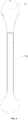
FIG. 1 is a front view of an electronic cigarette equipped with a cartridge of the present disclosure; -
FIG. 2 is a side view of an electronic cigarette equipped with a cartridge of the present disclosure; -
FIG. 3 is a cross-sectional view of an electronic cigarette equipped with a cartridge of the present disclosure; and -
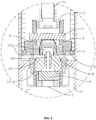
FIG. 4 is an enlarged view of the portion A inFIG. 3 . - The technical solution of the present disclosure will be described clearly and completely with reference to the drawings and the embodiments. It should be understood that the specific embodiments described herein are only used to explain the present disclosure and are not used to limit the protection scope of the present disclosure.
- Please refer to
FIGs. 1 to 4 , the present disclosure provides a cartridge. The cartridge includes a liquid storage chamber and an atomizing device. The atomizing device includes an atomizingbase 1, an atomizingcover 2, and a liquid absorbingmember 3 installed in the atomizingbase 1. The atomizingbase 1 defines an atomizing chamber therein. The atomizingbase 1 is made of an elastic material, such as silicone, rubber, or the like. The atomizingcover 2 is tightly mounted to the top of the atomizingbase 1, so that the atomizingcover 2 cooperates with the atomizingbase 1 to form the atomizing chamber therebetween. Two through holes are oppositely provided through the peripheral wall of the atomizingbase 1, and two ends of theliquid absorbing member 3 are tightly inserted into the two through holes, respectively. In another embodiment, the atomizingbase 1 may be made of a high-temperature resistant elastic material to avoid the irritating smell caused by the high temperature of the atomization. - Due to the elasticity of the atomizing
base 1, theliquid absorbing member 3 can be tightly fitted within the through holes of the atomizingbase 1, and the inner peripheral wall of the through holes can closely abut against the outer peripheral surface of the two ends of theliquid absorbing member 3, so that no gap causing e-liquid leakage exists between theliquid absorbing member 3 and the through holes, thereby effectively avoiding e-liquid leakage, achieving a good heat insulation effect, and simplifying the assembly process. In another embodiment, in order to ensure a tight fit, theliquid absorbing member 3 is made of a hard material, for example, the liquid absorbingmember 3 is a porous ceramic rod. The ceramic rod is porous and can absorb e-liquid , and its hardness is high, so it is more convenient to install. Otherwise, when theliquid absorbing member 3 is also a soft material, it will increase the difficulty of assembly. - The atomizing device further includes a
heating member 4. Theheating member 4 is wound around the outer peripheral surface of theliquid absorbing member 3. Two ends of theheating member 4 are respectively connected to power output terminals of the electronic cigarette. - The
liquid absorbing member 3 may be made of a hard material, such as a porous ceramic rod. When theliquid absorbing member 3 is a porous ceramic rod, it can be a hollow rod or a solid rod. When theliquid absorbing member 3 is a hollow rod, it can increase the contact area between the e-liquid and theliquid absorbing member 3, and provide e-liquid to theheating member 4 more quickly. Preferably, theheating member 4 is made of PTC alloy wire. Theheating member 4 may also be pre-built in ceramic material and then integrally formed by sintering. - The atomizing device further includes two
electrical conductors 5 and abottom cover 6. The twoelectrical conductors 5 are spaced apart and fixed at the bottom of theatomizing base 1 through thebottom cover 6. Thebottom cover 6 is an electrical insulator. The twoelectrical conductors 5 are electrically connected to two ends of theheating member 4, respectively. - The atomizing device further includes a
control board 7, asensor 8 and twoprobes 9. Thecontrol board 7 is electrically connected to power terminals of the electronic cigarette. Thesensor 8 is electrically connected to thecontrol board 7. The twoprobes 9 are electrically connected to power output terminals of thecontrol board 7. The twoprobes 9 are electrically connected to the twoelectrical conductors 5, respectively. Specifically, the top end of theprobe 9 is connected to the bottom end of theelectrical conductor 5, and the bottom end of theprobe 9 is fixed to thecontrol board 7. Thesensor 8 is used to detect the changes of airflow so as to determine whether the power is supplied to the atomization circuit using the twoprobes 9. - The present disclosure further provides an electronic cigarette. The electronic cigarette includes a
main body 10 and acartridge 11. Theatomizing base 1 and avent tube 12 are mounted in thecartridge 11. The bottom end of thecartridge 11 is fixedly connected to the bottom end of theatomizing base 1. The liquid storage chamber is formed between thecartridge 11 and theatomizing base 1. A mouthpiece is provided at the top of thecartridge 11. One end of thevent tube 12 is in communication with the mouthpiece, and the other end of thevent tube 12 is in communication with the top end of theatomizing cover 2. A fixingseat 14 is provided in themain body 10, and the fixingseat 14 divides the interior of themain body 10 into upper and lower spaces. Twomagnets 15 are fixedly connected to the fixingseat 14. The twoelectrical conductors 5 are made of stainless iron or stainless steel. Thecartridge 11 is detachably inserted into themain body 10, and the twoelectrical conductors 5 are respectively attracted by the twomagnets 15. A mounting cavity is formed at the bottom end of the fixing seat 14 (that is, the opposite end with respect to the magnets 15), and thesensor 8 is mounted in the mounting cavity. Anairflow passage 16 is defined in the fixingseat 14 and is correspondingly located above thesensor 8. Theairflow passage 16 is in communication with thebottom space 17 of theatomizing base 1. Theatomizing base 1 is provided with an air inlet hole used for the atomizing chamber to communicate with thebottom space 17. Themain body 10 is provided with an air suction hole used for thebottom space 17 to communicate with the outside. The air suction hole may be a gap between thecartridge 11 and themain body 10 after they are installed. - An
interface 18 for charging thebattery 13 or transmitting data is provided at the bottom end of themain body 10. - When a user sucks the mouthpiece, the
sensor 8 detects the changes of the airflow in thebottom space 17, for example, the changes of the flow rate of the airflow or the air pressure. When the range of the changes of the airflow meets the trigger condition, the output electrical current of thebattery 13 is supplied to the atomization circuit through the twoprobes 9, and theheating member 4 heats and atomizes the e-liquid. That is, the heat emitted by theheating member 4 atomizes the e-liquid absorbed in theliquid absorbing member 3. The outside air enters the atomizing chamber from thebottom space 17, the smoke generated by the atomized e-liquid enters the mouth from the atomizing chamber through thevent tube 12, so that the user can experience the feel of smoking. - In summary, the e-liquid generally leaks from the liquid inlet hole or the installation gap of the atomizing base in the existing electronic cigarettes. However, the
atomizing base 1 in the cartridge of the present disclosure is made of an elastic material, theatomizing base 1 is provided with through holes, theliquid absorbing member 3 extends through the through holes, and theliquid absorbing member 3 can be tightly fitted within the through holes of theatomizing base 1. That is, the inner peripheral wall of the through holes can closely abut against the outer peripheral surface of the two ends of theliquid absorbing member 3, so that no gap causing e-liquid leakage exists between the liquid absorbingmember 3 and the through holes, thereby effectively avoiding e-liquid leakage, achieving good isolation between e-liquid and vapor, and simplifying the assembly process. The electronic cigarette equipped with the above cartridge has the advantages of avoiding e-liquid leakage, good isolation between e-liquid and vapor, and simple assembly. - The above is only the embodiment of the present disclosure, and is not intended to limit the scope of the present disclosure. Any equivalent structure or equivalent process transformation made by using the content of the description of the present disclosure, or directly or indirectly applied in other related technical fields, is also included in the protection scope of the present disclosure.
Claims (10)
- A cartridge, comprising:a liquid storage chamber; andan atomizing device comprising an atomizing base (1) and a liquid absorbing member (3) installed in the atomizing base (1), the atomizing base (1) provided with an atomizing chamber therein;wherein the atomizing base (1) is made of an elastic material, the atomizing base (1) is provided with a through hole, the liquid absorbing member (3) extends through the through hole, the inner wall of the through hole closely abuts against the outer wall of the liquid absorbing member (3) to isolate the liquid storage chamber from the atomizing chamber.
- The cartridge according to the claim 1, wherein the through hole is provided in pairs through a peripheral wall of the atomizing base (1), the number of the liquid absorbing member (3) is the same as the number of the pairs of the through holes.
- The cartridge according to the claim 1, wherein the atomizing device further comprises a heating member (4), the heating member (4) is wound around an outer peripheral surface of the liquid absorbing member (3).
- The cartridge according to the claim 1, wherein the liquid absorbing member (3) is made of a hard material.
- The cartridge according to the claim 4, wherein the liquid absorbing member (3) is a porous ceramic rod, and the porous ceramic rod is a hollow rod or a solid rod.
- The cartridge according to the claim 3, wherein the atomizing device further comprises two electrical conductors (5) and a bottom cover (6), the two electrical conductors (5) are spaced apart and fixed at the bottom of the atomizing base (1) through the bottom cover (6), the two electrical conductors (5) are electrically connected to two ends of the heating member (4), respectively.
- An electronic cigarette, comprising:a main body (10); anda cartridge according to any one of claims 1 to 6;wherein the atomizing base (1) and a vent tube (12) are mounted in the cartridge (11), the bottom end of the cartridge (11) is connected to the bottom end of the atomizing base (1), a mouthpiece is provided at the top of the cartridge (11), one end of the vent tube (12) is in communication with the mouthpiece, the other end of the vent tube (12) is in communication with the atomizing base (1).
- The electronic cigarette according to the claim 7, wherein the main body (10) comprises a control board (7) and a sensor (8), a fixing seat (14) is provided in the main body (10), a mounting cavity is formed at the bottom end of the fixing seat (14), the sensor (8) is mounted in the mounting cavity and electrically connected to the control board (7).
- The electronic cigarette according to the claim 8, wherein the main body (10) further comprises two probes (9), the two probes (9) are electrically connected to power output terminals of the control board (7), the two probes (9) are respectively electrically connected with the two electrical conductors (5) arranged on the cartridge (11).
- The electronic cigarette according to the claim 8, wherein an airflow passage (16) is defined in the fixing seat (14) and is correspondingly located above the sensor (8), the airflow passage (16) is in communication with the atomizing chamber.
Applications Claiming Priority (2)
| Application Number | Priority Date | Filing Date | Title |
|---|---|---|---|
| CN201821733709.2U CN209346090U (en) | 2018-10-24 | 2018-10-24 | Cartridges and Electronic Cigarettes |
| PCT/CN2019/110694 WO2020083047A1 (en) | 2018-10-24 | 2019-10-12 | Cartridge and electronic cigarette |
Publications (3)
| Publication Number | Publication Date |
|---|---|
| EP3871537A1 true EP3871537A1 (en) | 2021-09-01 |
| EP3871537A4 EP3871537A4 (en) | 2022-08-10 |
| EP3871537B1 EP3871537B1 (en) | 2025-06-18 |
Family
ID=67781247
Family Applications (1)
| Application Number | Title | Priority Date | Filing Date |
|---|---|---|---|
| EP19875087.9A Active EP3871537B1 (en) | 2018-10-24 | 2019-10-12 | Cartridge and electronic cigarette |
Country Status (4)
| Country | Link |
|---|---|
| US (1) | US11992046B2 (en) |
| EP (1) | EP3871537B1 (en) |
| CN (1) | CN209346090U (en) |
| WO (1) | WO2020083047A1 (en) |
Families Citing this family (6)
| Publication number | Priority date | Publication date | Assignee | Title |
|---|---|---|---|---|
| CN209346090U (en) * | 2018-10-24 | 2019-09-06 | 常州市派腾电子技术服务有限公司 | Cartridges and Electronic Cigarettes |
| CN111150101A (en) * | 2020-01-19 | 2020-05-15 | 深圳尊一品科技有限公司 | Atomizer with air pressure buffer bin and application thereof |
| WO2022120526A1 (en) * | 2020-12-07 | 2022-06-16 | 深圳麦克韦尔科技有限公司 | Needle-shaped heating body and aerosol producing device |
| CN112790436B (en) * | 2021-01-30 | 2025-10-17 | 深圳市吉迩科技有限公司 | Main unit, atomizing device and aerosol generating device |
| CN113068871A (en) * | 2021-05-22 | 2021-07-06 | 深圳易佳特科技有限公司 | Air pressure balance atomizer and electronic cigarette |
| CN115191671B (en) * | 2022-06-28 | 2025-04-25 | 深圳市华诚达精密工业有限公司 | Electronic atomizer and atomizing device thereof |
Family Cites Families (16)
| Publication number | Priority date | Publication date | Assignee | Title |
|---|---|---|---|---|
| KR20120098343A (en) * | 2011-02-28 | 2012-09-05 | 주식회사 피앤디플러스 | Electronic cigarette |
| CN104114049A (en) * | 2012-03-26 | 2014-10-22 | 韩国极光科技有限公司 | Atomization control unit and a portable atomizing apparatus having the same |
| CN203168030U (en) * | 2012-06-05 | 2013-09-04 | 刘秋明 | Atomization device and its electronic cigarette |
| CN203575656U (en) * | 2013-11-13 | 2014-05-07 | 刘秋明 | Atomizer and electronic cigarette comprising same |
| CN107427072A (en) * | 2015-03-27 | 2017-12-01 | 惠州市吉瑞科技有限公司 | Atomizer |
| WO2016154895A1 (en) * | 2015-03-31 | 2016-10-06 | 惠州市吉瑞科技有限公司 | Atomizing component and electronic cigarette |
| CN205106387U (en) * | 2015-11-05 | 2016-03-30 | 刘志宾 | Electronic cigarette atomizer and electronic cigarette |
| CN108887746A (en) * | 2016-02-27 | 2018-11-27 | 卓尔悦欧洲控股有限公司 | Electronic cigarette |
| CN118319066A (en) * | 2016-04-22 | 2024-07-12 | 尤尔实验室有限公司 | Aerosol device with spacer material |
| CN105876869B (en) * | 2016-06-08 | 2020-02-14 | 卓尔悦欧洲控股有限公司 | Electronic cigarette |
| CN206079029U (en) * | 2016-09-09 | 2017-04-12 | 深圳市合元科技有限公司 | Electronic cigarette atomizer |
| CN106235419B (en) * | 2016-09-19 | 2023-10-27 | 深圳市康泓威科技有限公司 | Electronic cigarette atomizer with liquid storage transition chamber |
| US11129414B2 (en) * | 2016-12-27 | 2021-09-28 | Juul Labs, Inc. | Thermal wick for electronic vaporizers |
| CN206433763U (en) * | 2017-01-19 | 2017-08-25 | 深圳市凯德威科技有限公司 | A kind of electronic smoke atomizer |
| US10285444B2 (en) * | 2017-04-27 | 2019-05-14 | Rai Strategic Holdings, Inc. | Aerosol delivery device including a ceramic wicking element |
| CN209346090U (en) * | 2018-10-24 | 2019-09-06 | 常州市派腾电子技术服务有限公司 | Cartridges and Electronic Cigarettes |
-
2018
- 2018-10-24 CN CN201821733709.2U patent/CN209346090U/en active Active
-
2019
- 2019-10-12 WO PCT/CN2019/110694 patent/WO2020083047A1/en not_active Ceased
- 2019-10-12 EP EP19875087.9A patent/EP3871537B1/en active Active
-
2021
- 2021-04-25 US US17/239,677 patent/US11992046B2/en active Active
Also Published As
| Publication number | Publication date |
|---|---|
| EP3871537B1 (en) | 2025-06-18 |
| US11992046B2 (en) | 2024-05-28 |
| CN209346090U (en) | 2019-09-06 |
| WO2020083047A1 (en) | 2020-04-30 |
| US20210244093A1 (en) | 2021-08-12 |
| EP3871537A4 (en) | 2022-08-10 |
Similar Documents
| Publication | Publication Date | Title |
|---|---|---|
| US11992046B2 (en) | Cartridge and electronic cigarette | |
| CN110074464B (en) | Atomizer and electronic cigarette | |
| EP3895562B1 (en) | Atomizing head, atomizer and electronic cigarette | |
| CN205456048U (en) | Heating components, atomizers and electronic cigarettes | |
| CN204444248U (en) | Atomizer and electronic cigarette | |
| US12458071B2 (en) | Electronic atomization device | |
| CN107772541B (en) | Atomizer and electronic cigarette thereof | |
| CN206651392U (en) | Atomising head, atomizer and electronic cigarette | |
| WO2019196688A1 (en) | Atomizer and electronic cigarette | |
| US20190037920A1 (en) | Atomization core device and electronic cigarette | |
| US12329202B2 (en) | Electronic atomization device | |
| CN215455369U (en) | Electronic cigarette with function of preventing smoke oil and condensate leakage | |
| CN208002106U (en) | Atomizing component, atomizer and electronic cigarette | |
| CN106037009B (en) | Electrical steam device | |
| CN216019106U (en) | Atomizing core, atomizer and electronic atomization device | |
| US12250967B2 (en) | Electronic cigarette body, vaporization device, and electronic cigarette | |
| CN108618204A (en) | Atomizer and electronic cigarette | |
| CN219288750U (en) | Sliding connection type electronic cigarette | |
| CN111602862A (en) | Electronic cigarette power supply components and electronic cigarette | |
| CN210329333U (en) | Atomizer with lower pneumatic switch | |
| EP4487712A1 (en) | Aerosol product heating assembly and aerosol generation device | |
| CN218551326U (en) | Electronic atomization device and atomizer thereof | |
| CN207428412U (en) | Atomizer and its electronic cigarette | |
| CN214710368U (en) | Electronic atomizer capable of preventing tobacco tar from leaking | |
| CN212368328U (en) | Power supply assembly of electronic atomization device and electronic atomization device |
Legal Events
| Date | Code | Title | Description |
|---|---|---|---|
| STAA | Information on the status of an ep patent application or granted ep patent |
Free format text: STATUS: THE INTERNATIONAL PUBLICATION HAS BEEN MADE |
|
| PUAI | Public reference made under article 153(3) epc to a published international application that has entered the european phase |
Free format text: ORIGINAL CODE: 0009012 |
|
| STAA | Information on the status of an ep patent application or granted ep patent |
Free format text: STATUS: REQUEST FOR EXAMINATION WAS MADE |
|
| 17P | Request for examination filed |
Effective date: 20210507 |
|
| AK | Designated contracting states |
Kind code of ref document: A1 Designated state(s): AL AT BE BG CH CY CZ DE DK EE ES FI FR GB GR HR HU IE IS IT LI LT LU LV MC MK MT NL NO PL PT RO RS SE SI SK SM TR |
|
| DAV | Request for validation of the european patent (deleted) | ||
| DAX | Request for extension of the european patent (deleted) | ||
| A4 | Supplementary search report drawn up and despatched |
Effective date: 20220711 |
|
| RIC1 | Information provided on ipc code assigned before grant |
Ipc: A24F 40/44 20200101ALI20220705BHEP Ipc: A24F 40/42 20200101ALI20220705BHEP Ipc: A24F 40/40 20200101AFI20220705BHEP |
|
| REG | Reference to a national code |
Ref country code: DE Ref legal event code: R079 Free format text: PREVIOUS MAIN CLASS: A24F0047000000 Ipc: A24F0040400000 Ref country code: DE Ref legal event code: R079 Ref document number: 602019071377 Country of ref document: DE Free format text: PREVIOUS MAIN CLASS: A24F0047000000 Ipc: A24F0040400000 |
|
| STAA | Information on the status of an ep patent application or granted ep patent |
Free format text: STATUS: EXAMINATION IS IN PROGRESS |
|
| RIC1 | Information provided on ipc code assigned before grant |
Ipc: A24F 40/44 20200101ALI20230327BHEP Ipc: A24F 40/42 20200101ALI20230327BHEP Ipc: A24F 40/40 20200101AFI20230327BHEP |
|
| 17Q | First examination report despatched |
Effective date: 20230406 |
|
| GRAP | Despatch of communication of intention to grant a patent |
Free format text: ORIGINAL CODE: EPIDOSNIGR1 |
|
| STAA | Information on the status of an ep patent application or granted ep patent |
Free format text: STATUS: GRANT OF PATENT IS INTENDED |
|
| GRAS | Grant fee paid |
Free format text: ORIGINAL CODE: EPIDOSNIGR3 |
|
| GRAA | (expected) grant |
Free format text: ORIGINAL CODE: 0009210 |
|
| STAA | Information on the status of an ep patent application or granted ep patent |
Free format text: STATUS: THE PATENT HAS BEEN GRANTED |
|
| INTG | Intention to grant announced |
Effective date: 20250417 |
|
| AK | Designated contracting states |
Kind code of ref document: B1 Designated state(s): AL AT BE BG CH CY CZ DE DK EE ES FI FR GB GR HR HU IE IS IT LI LT LU LV MC MK MT NL NO PL PT RO RS SE SI SK SM TR |
|
| REG | Reference to a national code |
Ref country code: GB Ref legal event code: FG4D |
|
| P01 | Opt-out of the competence of the unified patent court (upc) registered |
Free format text: CASE NUMBER: APP_23100/2025 Effective date: 20250515 |
|
| REG | Reference to a national code |
Ref country code: CH Ref legal event code: EP |
|
| REG | Reference to a national code |
Ref country code: DE Ref legal event code: R096 Ref document number: 602019071377 Country of ref document: DE |
|
| REG | Reference to a national code |
Ref country code: CH Ref legal event code: EP |
|
| REG | Reference to a national code |
Ref country code: IE Ref legal event code: FG4D |
|
| PG25 | Lapsed in a contracting state [announced via postgrant information from national office to epo] |
Ref country code: FI Free format text: LAPSE BECAUSE OF FAILURE TO SUBMIT A TRANSLATION OF THE DESCRIPTION OR TO PAY THE FEE WITHIN THE PRESCRIBED TIME-LIMIT Effective date: 20250618 |
|
| REG | Reference to a national code |
Ref country code: LT Ref legal event code: MG9D |
|
| PG25 | Lapsed in a contracting state [announced via postgrant information from national office to epo] |
Ref country code: NO Free format text: LAPSE BECAUSE OF FAILURE TO SUBMIT A TRANSLATION OF THE DESCRIPTION OR TO PAY THE FEE WITHIN THE PRESCRIBED TIME-LIMIT Effective date: 20250918 Ref country code: GR Free format text: LAPSE BECAUSE OF FAILURE TO SUBMIT A TRANSLATION OF THE DESCRIPTION OR TO PAY THE FEE WITHIN THE PRESCRIBED TIME-LIMIT Effective date: 20250919 |
|
| PG25 | Lapsed in a contracting state [announced via postgrant information from national office to epo] |
Ref country code: BG Free format text: LAPSE BECAUSE OF FAILURE TO SUBMIT A TRANSLATION OF THE DESCRIPTION OR TO PAY THE FEE WITHIN THE PRESCRIBED TIME-LIMIT Effective date: 20250618 |
|
| PGFP | Annual fee paid to national office [announced via postgrant information from national office to epo] |
Ref country code: GB Payment date: 20250917 Year of fee payment: 7 |
|
| PG25 | Lapsed in a contracting state [announced via postgrant information from national office to epo] |
Ref country code: HR Free format text: LAPSE BECAUSE OF FAILURE TO SUBMIT A TRANSLATION OF THE DESCRIPTION OR TO PAY THE FEE WITHIN THE PRESCRIBED TIME-LIMIT Effective date: 20250618 |
|
| PGFP | Annual fee paid to national office [announced via postgrant information from national office to epo] |
Ref country code: FR Payment date: 20250917 Year of fee payment: 7 |
|
| PG25 | Lapsed in a contracting state [announced via postgrant information from national office to epo] |
Ref country code: RS Free format text: LAPSE BECAUSE OF FAILURE TO SUBMIT A TRANSLATION OF THE DESCRIPTION OR TO PAY THE FEE WITHIN THE PRESCRIBED TIME-LIMIT Effective date: 20250918 |
|
| REG | Reference to a national code |
Ref country code: NL Ref legal event code: MP Effective date: 20250618 |
|
| PG25 | Lapsed in a contracting state [announced via postgrant information from national office to epo] |
Ref country code: LV Free format text: LAPSE BECAUSE OF FAILURE TO SUBMIT A TRANSLATION OF THE DESCRIPTION OR TO PAY THE FEE WITHIN THE PRESCRIBED TIME-LIMIT Effective date: 20250618 |
|
| PG25 | Lapsed in a contracting state [announced via postgrant information from national office to epo] |
Ref country code: NL Free format text: LAPSE BECAUSE OF FAILURE TO SUBMIT A TRANSLATION OF THE DESCRIPTION OR TO PAY THE FEE WITHIN THE PRESCRIBED TIME-LIMIT Effective date: 20250618 |
|
| PG25 | Lapsed in a contracting state [announced via postgrant information from national office to epo] |
Ref country code: PT Free format text: LAPSE BECAUSE OF FAILURE TO SUBMIT A TRANSLATION OF THE DESCRIPTION OR TO PAY THE FEE WITHIN THE PRESCRIBED TIME-LIMIT Effective date: 20251020 |
|
| REG | Reference to a national code |
Ref country code: AT Ref legal event code: MK05 Ref document number: 1803366 Country of ref document: AT Kind code of ref document: T Effective date: 20250618 |
|
| PG25 | Lapsed in a contracting state [announced via postgrant information from national office to epo] |
Ref country code: IS Free format text: LAPSE BECAUSE OF FAILURE TO SUBMIT A TRANSLATION OF THE DESCRIPTION OR TO PAY THE FEE WITHIN THE PRESCRIBED TIME-LIMIT Effective date: 20251018 |
|
| PGFP | Annual fee paid to national office [announced via postgrant information from national office to epo] |
Ref country code: DE Payment date: 20250923 Year of fee payment: 7 |
|
| PG25 | Lapsed in a contracting state [announced via postgrant information from national office to epo] |
Ref country code: AT Free format text: LAPSE BECAUSE OF FAILURE TO SUBMIT A TRANSLATION OF THE DESCRIPTION OR TO PAY THE FEE WITHIN THE PRESCRIBED TIME-LIMIT Effective date: 20250618 Ref country code: SM Free format text: LAPSE BECAUSE OF FAILURE TO SUBMIT A TRANSLATION OF THE DESCRIPTION OR TO PAY THE FEE WITHIN THE PRESCRIBED TIME-LIMIT Effective date: 20250618 |
|
| PG25 | Lapsed in a contracting state [announced via postgrant information from national office to epo] |
Ref country code: CZ Free format text: LAPSE BECAUSE OF FAILURE TO SUBMIT A TRANSLATION OF THE DESCRIPTION OR TO PAY THE FEE WITHIN THE PRESCRIBED TIME-LIMIT Effective date: 20250618 |
|
| PG25 | Lapsed in a contracting state [announced via postgrant information from national office to epo] |
Ref country code: PL Free format text: LAPSE BECAUSE OF FAILURE TO SUBMIT A TRANSLATION OF THE DESCRIPTION OR TO PAY THE FEE WITHIN THE PRESCRIBED TIME-LIMIT Effective date: 20250618 |
|
| PG25 | Lapsed in a contracting state [announced via postgrant information from national office to epo] |
Ref country code: EE Free format text: LAPSE BECAUSE OF FAILURE TO SUBMIT A TRANSLATION OF THE DESCRIPTION OR TO PAY THE FEE WITHIN THE PRESCRIBED TIME-LIMIT Effective date: 20250618 |
|
| PG25 | Lapsed in a contracting state [announced via postgrant information from national office to epo] |
Ref country code: RO Free format text: LAPSE BECAUSE OF FAILURE TO SUBMIT A TRANSLATION OF THE DESCRIPTION OR TO PAY THE FEE WITHIN THE PRESCRIBED TIME-LIMIT Effective date: 20250618 Ref country code: SK Free format text: LAPSE BECAUSE OF FAILURE TO SUBMIT A TRANSLATION OF THE DESCRIPTION OR TO PAY THE FEE WITHIN THE PRESCRIBED TIME-LIMIT Effective date: 20250618 |
|
| PG25 | Lapsed in a contracting state [announced via postgrant information from national office to epo] |
Ref country code: ES Free format text: LAPSE BECAUSE OF FAILURE TO SUBMIT A TRANSLATION OF THE DESCRIPTION OR TO PAY THE FEE WITHIN THE PRESCRIBED TIME-LIMIT Effective date: 20250618 |
|
| REG | Reference to a national code |
Ref country code: DE Ref legal event code: R097 Ref document number: 602019071377 Country of ref document: DE |
|
| PG25 | Lapsed in a contracting state [announced via postgrant information from national office to epo] |
Ref country code: DK Free format text: LAPSE BECAUSE OF FAILURE TO SUBMIT A TRANSLATION OF THE DESCRIPTION OR TO PAY THE FEE WITHIN THE PRESCRIBED TIME-LIMIT Effective date: 20250618 |
|
| PG25 | Lapsed in a contracting state [announced via postgrant information from national office to epo] |
Ref country code: IT Free format text: LAPSE BECAUSE OF FAILURE TO SUBMIT A TRANSLATION OF THE DESCRIPTION OR TO PAY THE FEE WITHIN THE PRESCRIBED TIME-LIMIT Effective date: 20250618 |
|
| PLBE | No opposition filed within time limit |
Free format text: ORIGINAL CODE: 0009261 |
|
| STAA | Information on the status of an ep patent application or granted ep patent |
Free format text: STATUS: NO OPPOSITION FILED WITHIN TIME LIMIT |
|
| REG | Reference to a national code |
Ref country code: CH Ref legal event code: L10 Free format text: ST27 STATUS EVENT CODE: U-0-0-L10-L00 (AS PROVIDED BY THE NATIONAL OFFICE) Effective date: 20260430 |