EP3870845B1 - Dämpfung von schwingungen in einer windturbine - Google Patents
Dämpfung von schwingungen in einer windturbine Download PDFInfo
- Publication number
- EP3870845B1 EP3870845B1 EP19801762.6A EP19801762A EP3870845B1 EP 3870845 B1 EP3870845 B1 EP 3870845B1 EP 19801762 A EP19801762 A EP 19801762A EP 3870845 B1 EP3870845 B1 EP 3870845B1
- Authority
- EP
- European Patent Office
- Prior art keywords
- wind turbine
- rotor blade
- vibrations
- blade
- aerodynamic
- Prior art date
- Legal status (The legal status is an assumption and is not a legal conclusion. Google has not performed a legal analysis and makes no representation as to the accuracy of the status listed.)
- Active
Links
- 238000013016 damping Methods 0.000 title claims description 8
- 238000000034 method Methods 0.000 claims description 17
- 230000001133 acceleration Effects 0.000 claims description 3
- 230000001105 regulatory effect Effects 0.000 description 11
- 230000000694 effects Effects 0.000 description 3
- 239000012530 fluid Substances 0.000 description 3
- 230000004913 activation Effects 0.000 description 2
- 230000010355 oscillation Effects 0.000 description 2
- 230000001276 controlling effect Effects 0.000 description 1
- 230000001419 dependent effect Effects 0.000 description 1
- 230000005611 electricity Effects 0.000 description 1
- 230000002708 enhancing effect Effects 0.000 description 1
- 238000012544 monitoring process Methods 0.000 description 1
- 238000010248 power generation Methods 0.000 description 1
- 238000000926 separation method Methods 0.000 description 1
- 230000001502 supplementing effect Effects 0.000 description 1
Images


Classifications
-
- F—MECHANICAL ENGINEERING; LIGHTING; HEATING; WEAPONS; BLASTING
- F03—MACHINES OR ENGINES FOR LIQUIDS; WIND, SPRING, OR WEIGHT MOTORS; PRODUCING MECHANICAL POWER OR A REACTIVE PROPULSIVE THRUST, NOT OTHERWISE PROVIDED FOR
- F03D—WIND MOTORS
- F03D7/00—Controlling wind motors
- F03D7/02—Controlling wind motors the wind motors having rotation axis substantially parallel to the air flow entering the rotor
- F03D7/0296—Controlling wind motors the wind motors having rotation axis substantially parallel to the air flow entering the rotor to prevent, counteract or reduce noise emissions
-
- F—MECHANICAL ENGINEERING; LIGHTING; HEATING; WEAPONS; BLASTING
- F03—MACHINES OR ENGINES FOR LIQUIDS; WIND, SPRING, OR WEIGHT MOTORS; PRODUCING MECHANICAL POWER OR A REACTIVE PROPULSIVE THRUST, NOT OTHERWISE PROVIDED FOR
- F03D—WIND MOTORS
- F03D7/00—Controlling wind motors
- F03D7/02—Controlling wind motors the wind motors having rotation axis substantially parallel to the air flow entering the rotor
- F03D7/022—Adjusting aerodynamic properties of the blades
- F03D7/0224—Adjusting blade pitch
-
- F—MECHANICAL ENGINEERING; LIGHTING; HEATING; WEAPONS; BLASTING
- F03—MACHINES OR ENGINES FOR LIQUIDS; WIND, SPRING, OR WEIGHT MOTORS; PRODUCING MECHANICAL POWER OR A REACTIVE PROPULSIVE THRUST, NOT OTHERWISE PROVIDED FOR
- F03D—WIND MOTORS
- F03D7/00—Controlling wind motors
- F03D7/02—Controlling wind motors the wind motors having rotation axis substantially parallel to the air flow entering the rotor
- F03D7/022—Adjusting aerodynamic properties of the blades
- F03D7/0232—Adjusting aerodynamic properties of the blades with flaps or slats
-
- F—MECHANICAL ENGINEERING; LIGHTING; HEATING; WEAPONS; BLASTING
- F05—INDEXING SCHEMES RELATING TO ENGINES OR PUMPS IN VARIOUS SUBCLASSES OF CLASSES F01-F04
- F05B—INDEXING SCHEME RELATING TO WIND, SPRING, WEIGHT, INERTIA OR LIKE MOTORS, TO MACHINES OR ENGINES FOR LIQUIDS COVERED BY SUBCLASSES F03B, F03D AND F03G
- F05B2240/00—Components
- F05B2240/20—Rotors
- F05B2240/30—Characteristics of rotor blades, i.e. of any element transforming dynamic fluid energy to or from rotational energy and being attached to a rotor
- F05B2240/305—Flaps, slats or spoilers
- F05B2240/3052—Flaps, slats or spoilers adjustable
-
- F—MECHANICAL ENGINEERING; LIGHTING; HEATING; WEAPONS; BLASTING
- F05—INDEXING SCHEMES RELATING TO ENGINES OR PUMPS IN VARIOUS SUBCLASSES OF CLASSES F01-F04
- F05B—INDEXING SCHEME RELATING TO WIND, SPRING, WEIGHT, INERTIA OR LIKE MOTORS, TO MACHINES OR ENGINES FOR LIQUIDS COVERED BY SUBCLASSES F03B, F03D AND F03G
- F05B2240/00—Components
- F05B2240/20—Rotors
- F05B2240/30—Characteristics of rotor blades, i.e. of any element transforming dynamic fluid energy to or from rotational energy and being attached to a rotor
- F05B2240/306—Surface measures
- F05B2240/3062—Vortex generators
-
- F—MECHANICAL ENGINEERING; LIGHTING; HEATING; WEAPONS; BLASTING
- F05—INDEXING SCHEMES RELATING TO ENGINES OR PUMPS IN VARIOUS SUBCLASSES OF CLASSES F01-F04
- F05B—INDEXING SCHEME RELATING TO WIND, SPRING, WEIGHT, INERTIA OR LIKE MOTORS, TO MACHINES OR ENGINES FOR LIQUIDS COVERED BY SUBCLASSES F03B, F03D AND F03G
- F05B2260/00—Function
- F05B2260/96—Preventing, counteracting or reducing vibration or noise
- F05B2260/964—Preventing, counteracting or reducing vibration or noise by damping means
-
- F—MECHANICAL ENGINEERING; LIGHTING; HEATING; WEAPONS; BLASTING
- F05—INDEXING SCHEMES RELATING TO ENGINES OR PUMPS IN VARIOUS SUBCLASSES OF CLASSES F01-F04
- F05B—INDEXING SCHEME RELATING TO WIND, SPRING, WEIGHT, INERTIA OR LIKE MOTORS, TO MACHINES OR ENGINES FOR LIQUIDS COVERED BY SUBCLASSES F03B, F03D AND F03G
- F05B2270/00—Control
- F05B2270/30—Control parameters, e.g. input parameters
- F05B2270/334—Vibration measurements
-
- F—MECHANICAL ENGINEERING; LIGHTING; HEATING; WEAPONS; BLASTING
- F05—INDEXING SCHEMES RELATING TO ENGINES OR PUMPS IN VARIOUS SUBCLASSES OF CLASSES F01-F04
- F05B—INDEXING SCHEME RELATING TO WIND, SPRING, WEIGHT, INERTIA OR LIKE MOTORS, TO MACHINES OR ENGINES FOR LIQUIDS COVERED BY SUBCLASSES F03B, F03D AND F03G
- F05B2270/00—Control
- F05B2270/80—Devices generating input signals, e.g. transducers, sensors, cameras or strain gauges
- F05B2270/807—Accelerometers
-
- F—MECHANICAL ENGINEERING; LIGHTING; HEATING; WEAPONS; BLASTING
- F05—INDEXING SCHEMES RELATING TO ENGINES OR PUMPS IN VARIOUS SUBCLASSES OF CLASSES F01-F04
- F05B—INDEXING SCHEME RELATING TO WIND, SPRING, WEIGHT, INERTIA OR LIKE MOTORS, TO MACHINES OR ENGINES FOR LIQUIDS COVERED BY SUBCLASSES F03B, F03D AND F03G
- F05B2270/00—Control
- F05B2270/80—Devices generating input signals, e.g. transducers, sensors, cameras or strain gauges
- F05B2270/808—Strain gauges; Load cells
-
- Y—GENERAL TAGGING OF NEW TECHNOLOGICAL DEVELOPMENTS; GENERAL TAGGING OF CROSS-SECTIONAL TECHNOLOGIES SPANNING OVER SEVERAL SECTIONS OF THE IPC; TECHNICAL SUBJECTS COVERED BY FORMER USPC CROSS-REFERENCE ART COLLECTIONS [XRACs] AND DIGESTS
- Y02—TECHNOLOGIES OR APPLICATIONS FOR MITIGATION OR ADAPTATION AGAINST CLIMATE CHANGE
- Y02E—REDUCTION OF GREENHOUSE GAS [GHG] EMISSIONS, RELATED TO ENERGY GENERATION, TRANSMISSION OR DISTRIBUTION
- Y02E10/00—Energy generation through renewable energy sources
- Y02E10/70—Wind energy
- Y02E10/72—Wind turbines with rotation axis in wind direction
Definitions
- the present invention relates to a method for monitoring and damping excessive vibrations in a wind turbine.
- a wind turbine rotor blade may have installed a flow regulating device on its surface, which flows from the leading edge to the trailing edge of a rotor blade of a wind turbine.
- a flow regulating device is a vortex generator (VG) installed on the suction side of the wind turbine rotor blade.
- VG vortex generator
- a flow regulating device may be considered to comprise a device which is capable of enhancing the lift coefficient of the aerofoil section, for example by increasing the level of energy of the boundary layer of the rotor blade.
- Aerodynamic devices may act in concert with the vortex generator and may influence the effect of the vortex generator depending on the state of the spoiler.
- Examples of the latter aerodynamic device are typically spoilers, installed on the suction side of the blade, between the trailing edge and the vortex generator.
- spoilers may be present alone, i.e. not combined with vortex generators or other flow regulating devices.
- Spoilers may be configured such that its shape and/or orientation can be regulated, e.g. by a pneumatic or hydraulic or mechanical actuator.
- the spoiler may act in concert with the vortex generator and may influence the effect of the vortex generator depending on the state of the spoiler, i.e. a protrusion height and/or tilt angle by which the spoiler extends from or is tilted relative to other surface portions of the rotor blade.
- EP 1 623 111 B1 discloses a wind turbine blade including adjustable lift-regulating means arranged on or at the surface of the wind turbine blade and extending in the longitudinal direction of the blade and an activation means by which the lift-regulating means can be adjusted and thus alter the aerodynamic properties of the blade.
- the lift-regulating means comprise one or more flexible flaps.
- US 8 851 840 B2 discloses a wind turbine blade comprising a blade body and a device for modifying the aerodynamic surface or shape of the blade, wherein a pneumatic actuator controls the position and/or movement of the device, wherein a pressure chamber positioned within the blade body is present.
- the pressure chamber may be pressurized thereby changing the state of the device, thereby modifying the aerodynamic surface or shape of the blade.
- US 5 106 265 A discloses a wind turbine wing comprising a pneumatically actuated spoiler movable perpendicular to an airstream.
- WO 2018/041420 discloses a rotor blade comprising an aerodynamic device for influencing the airflow flowing from the leading edge section of the rotor blade to the trailing edge section of the rotor blade, wherein the aerodynamic device is mounted at a surface of the rotor blade and comprises a pneumatic or hydraulic actuator, such as a hose or a cavity of which the volume depends on the pressure of the fluid being present inside the pneumatic or hydraulic actuator.
- a pneumatic or hydraulic actuator such as a hose or a cavity of which the volume depends on the pressure of the fluid being present inside the pneumatic or hydraulic actuator.
- WO 2010/084131 A2 discloses a method of damping vibrations in tower of a wind turbine induced by an emergency shut-down which integrates pitching of the blades with the use of flaps.
- a method for damping vibration in a wind turbine including a plurality of aerodynamic devices for influencing the airflow flowing from the leading edge of a rotor blade of the wind turbine to the trailing edge of the rotor blade, each aerodynamic device being movable by an actuator between a first protruded configuration and a second retracted configuration.
- the method comprises the steps of:
- the method of the present invention allows that the activation of the aerodynamic devices in the first protruded configuration does not cause instability problems in the blade.
- the aerodynamic devices are flaps, i.e. an aerodynamic devices installed at the trailing edge of the rotor blade.
- the aerodynamic devices are spoilers, i.e. an aerodynamic device installed in a position intermediate between the leading edge and the trailing edge of the rotor blade.
- flaps and spoilers are together provided on the rotor blade.
- the pitch angle interval of the rotor blade extends between a minimum pitch angle and a maximum pitch angle. According to embodiments of the present invention, the pitch angle interval is reduced by increasing the minimum pitch angle of the rotor blade.
- the method of the present invention damps vibrations around the first blade flap mode.
- the first blade flap mode is the first oscillations mode of the rotor blade in a direction orthogonal to the chord of an aerofoil section of the rotor blade.
- vibrations may be measured by means of:
- FIG. 1 shows a conventional wind turbine 10 for generating electricity.
- the wind turbine 10 comprises a tower 11 which is mounted on the ground 16 at one end. At the opposite end of the tower 11 there is mounted a nacelle 12.
- the nacelle 12 is usually mounted rotatable with regard to the tower 11, which is referred to as comprising a yaw axis substantially perpendicular to the ground 16.
- the nacelle 12 usually accommodates the generator of the wind turbine and the gear box (if the wind turbine is a geared wind turbine).
- the wind turbine 10 comprises a hub 13 which is rotatable about a rotor axis Y.
- the terms axial, radial and circumferential in the following are made with reference to the rotor axis Y.
- the hub 13 is often described as being a part of a wind turbine rotor, wherein the wind turbine rotor is capable to rotate about the rotor axis Y and to transfer the rotational energy to an electrical generator (not shown).
- the wind turbine 1 further comprises at least one blade 20 (in the embodiment of Figure 1 , the wind rotor comprises three blades 20, of which only two blades 20 are visible) mounted on the hub 13.
- the blades 4 extend substantially radially with respect to the rotational axis Y.
- Each rotor blade 20 is usually mounted pivotable to the hub 13, in order to be pitched about respective pitch axes X. This improves the control of the wind turbine and in particular of the rotor blades by the possibility of modifying the direction at which the wind is hitting the rotor blades 20.
- Each rotor blade 20 is mounted to the hub 13 at its root section 21. The root section 21 is opposed to the tip section 22 of the rotor blade.
- a pitch actuation system (either electric or hydraulic) is associated to the rotor blades 20 proximal to the respective root sections 21 for regulating the pitch angle of each blade.
- one single pitch actuation system may be provided for all rotor blades 20 or a plurality of pitch actuation systems may be provided, each serving one respective blade 20.
- the pitch angle of each rotor blade 20 extends between a minimum pitch angle and a maximum pitch angle.
- FIG. 2 illustrates the rotor blade 20 comprising an aerodynamic device 30 in the form of an actuated spoiler.
- the rotor blade 20 furthermore comprises a plurality of aerofoil sections for generating lift.
- Each aerofoil section comprises a suction side 25 and a pressure side 26.
- the aerofoil shape of the aerofoil portion is symbolized by one aerofoil profile which is shown in Figure 2 and which illustrates the cross-sectional shape of the rotor blade at this spanwise position.
- the suction side 25 is divided or separated from the pressure side 26 by a chord line 27 which connects a leading edge 41 with a trailing edge 31 of the rotor blade 20.
- the aerodynamic device 30 in Figure 2 is movable by means of a pressure line 53 connected to a pneumatic actuator 34.
- the pneumatic actuator 34 is realized as a hose.
- the hose 34 comprises an elastic outer skin, such that it can inflate and deflate reversibly and during many cycles when operated by means of the pressure line 53.
- the pressure line 53 is comprised in a pressure supply system 52 and controlled by a control unit 51.
- the pressure supply system 52 provides pressurized air or other pressurized gas, to the pneumatic actuator 34.
- pressurized fluid not only implies positive pressure but also negative pressure, wherein fluid is sucked (or “drawn") out of the pneumatic actuator 34.
- the pressure line 53 could be in practice realized as tubes or pipes which do not significantly change their volume.
- the control unit 51 is responsible for setting a specific pressure at the pressure supply system 52 which subsequently leads to a certain predetermined pressure at the pneumatic actuator 34. By controlling the pressure of the pressurized air the pneumatic actuator 34 is operated between an inflated and a deflated configuration.
- any of the control unit 51 and the pressure supply system 52 may be located in the root section 21 of the rotor blade 20 or placed elsewhere in the wind turbine, such as e.g. in the hub 13 of the wind turbine 10 or in the nacelle 12 or in the tower 11.
- the rotor blade 20 additionally comprises a flow regulating unit 40, not falling under the scope of the claims, comprising multiple pairs of vortex generators.
- the flow regulating unit 40 is arranged on the suction side 25 of the blade 20 between the aerodynamic device 30 and the the trailing edge 31.
- the flow regulating unit 40 is arranged on the suction side 25 of the blade 20 between the leading edge 41 and the aerodynamic device 30.
- the flow regulating unit 40 is not present and only the aerodynamic device 30 is used to regulate the flow on the surface of the blade 20.
- the blade 20 comprises a plurality of aerodynamic devices 30.
- the aerodynamic device 30 are configured as a trailing edge flap.
- the blade 20 may comprise a plurality of aerodynamic devices 30 including flaps and spoilers.
- the rotor blade 20 additionally comprises one sensor 54 for measuring vibrations or loads on the rotor blade 20.
- the sensor 54 is connected to the control unit 51 for transmitting a vibration or load signal.
- the blade 20 may comprise a plurality of vibration or load sensors 54, distributed along the rotor blade 20.
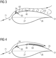
- Figure 3 shows the aerodynamic device 30 in a first protruded configuration, corresponding to an inflated configuration of the pneumatic actuator 34.
- the aerodynamic device 30 deviates the airflow 71 which is flowing from the leading edge 41 to the trailing edge 31 of the rotor blade.
- the aerodynamic device 30 in the first protruded configuration induces stall. This is visualized with relatively large vortices 63 downstream of the aerodynamic device 30. A consequence of the induced stall is a decrease in lift of the rotor blade and, consequently, a reduced loading of the rotor blade and related components of the wind turbine.
- Figure 4 shows the aerodynamic device 30 in a second retracted configuration, i.e. moved downwards towards the surface of the rotor blade 20, corresponding to a deflated configuration of the pneumatic actuator 34.
- the aerodynamic device 30 By operating the pneumatic actuator 34 of the aerodynamic device 30 through the pressure line 53, the aerodynamic device 30 can be moved between the first protruded configuration and the second retracted configuration in order to vary the aerodynamic properties of the blade as desired and requested when operating the wind turbine 10.
- a vibration when a vibration is detected, which is greater than a predefined threshold within a predefined frequency band, such vibration can be damped by operating the aerodynamic devices 30 alone or in combination with the blade pitch angle.
- a vibration of the wind turbine 10 may be detected through the sensors 54 or through other sensors (not shown in the attached figures). For example vibrations may be measured also by means of an acceleration sensor installed on the tower or nacelle.
- the present invention permits to damp vibrations around the first blade flap mode.
- the method comprises the steps of:
- the pitch angle interval of the rotor blade is reduced by increasing the minimum pitch angle of the rotor blade.
Landscapes
- Engineering & Computer Science (AREA)
- Mechanical Engineering (AREA)
- Sustainable Development (AREA)
- Sustainable Energy (AREA)
- Chemical & Material Sciences (AREA)
- Combustion & Propulsion (AREA)
- Life Sciences & Earth Sciences (AREA)
- General Engineering & Computer Science (AREA)
- Physics & Mathematics (AREA)
- Fluid Mechanics (AREA)
- Wind Motors (AREA)
- Buildings Adapted To Withstand Abnormal External Influences (AREA)
- Vibration Prevention Devices (AREA)
Claims (7)
- Verfahren zum Dämpfen von Schwingung in einer Windenergieanlage (10), die eine Mehrzahl von aerodynamischen Vorrichtungen (30) zum Beeinflussen der Luftströmung (61), die von der Vorderkante (41) eines Rotorblatts (20) der Windenergieanlage (10) zur Hinterkante (31) des Rotorblatts (20) strömt, umfasst, wobei jede aerodynamische Vorrichtung (30) durch einen Aktuator zwischen einer ersten hervorstehenden Auslegung und einer zweiten zurückgezogenen Auslegung beweglich ist, wobei das Verfahren die folgenden Schritte umfasst:- Messen von Schwingungen in der Windenergieanlage (10),- wenn die gemessenen Schwingungen größer als ein vordefinierter Schwellenwert innerhalb eines vordefinierten Frequenzbands sind, Bewegen eines Abschnitts der aerodynamischen Vorrichtungen (30) in die zweite zurückgezogene Auslegung und Fortfahren mit dem Messen von Schwingungen in der Windenergieanlage (10),- wenn die gemessenen Schwingungen immer noch größer als ein vordefinierter Schwellenwert innerhalb eines vordefinierten Frequenzbands sind, Reduzieren des Einstellwinkelintervalls des Rotorblatts (20) und Fortfahren mit dem Messen von Schwingungen in der Windenergieanlage (10),- wenn die gemessenen Schwingungen immer noch größer als ein vordefinierter Schwellenwert innerhalb eines vordefinierten Frequenzbands sind, Bewegen sämtlicher der aerodynamischen Vorrichtungen (30) in die zweite zurückgezogene Auslegung.
- Verfahren nach Anspruch 1, wobei das Einstellwinkelintervall des Rotorblatts (20) durch Erhöhen des minimalen Einstellwinkels des Rotorblatts (20) reduziert wird.
- Verfahren nach Anspruch 1 oder 2, wobei das vordefinierte Frequenzband den ersten Blattklappenmodus umfasst.
- Verfahren nach einem der vorhergehenden Ansprüche, wobei Schwingungen mittels eines Beschleunigungssensors gemessen werden, der an dem Turm (11) oder an der Gondel (12) der Windenergieanlage (10) oder an dem Rotorblatt (20) installiert ist.
- Verfahren nach einem der vorhergehenden Ansprüche, wobei Schwingungen mittels eines Lastsensors gemessen werden, der an dem Turm (11) oder an der Gondel (12) der Windenergieanlage (10) oder an dem Rotorblatt (20) installiert ist.
- Verfahren nach einem der vorhergehenden Ansprüche, wobei die aerodynamischen Vorrichtungen (30) Klappen sind.
- Verfahren nach einem der vorhergehenden Ansprüche, wobei die aerodynamischen Vorrichtungen (30) Spoiler sind.
Applications Claiming Priority (2)
| Application Number | Priority Date | Filing Date | Title |
|---|---|---|---|
| EP18212370.3A EP3667064A1 (de) | 2018-12-13 | 2018-12-13 | Dämpfung von schwingungen in einer windturbine |
| PCT/EP2019/079839 WO2020120017A1 (en) | 2018-12-13 | 2019-10-31 | Damping vibrations in a wind turbine |
Publications (2)
| Publication Number | Publication Date |
|---|---|
| EP3870845A1 EP3870845A1 (de) | 2021-09-01 |
| EP3870845B1 true EP3870845B1 (de) | 2023-06-07 |
Family
ID=64665456
Family Applications (2)
| Application Number | Title | Priority Date | Filing Date |
|---|---|---|---|
| EP18212370.3A Withdrawn EP3667064A1 (de) | 2018-12-13 | 2018-12-13 | Dämpfung von schwingungen in einer windturbine |
| EP19801762.6A Active EP3870845B1 (de) | 2018-12-13 | 2019-10-31 | Dämpfung von schwingungen in einer windturbine |
Family Applications Before (1)
| Application Number | Title | Priority Date | Filing Date |
|---|---|---|---|
| EP18212370.3A Withdrawn EP3667064A1 (de) | 2018-12-13 | 2018-12-13 | Dämpfung von schwingungen in einer windturbine |
Country Status (6)
| Country | Link |
|---|---|
| US (1) | US11454213B2 (de) |
| EP (2) | EP3667064A1 (de) |
| CN (1) | CN113167232B (de) |
| DK (1) | DK3870845T3 (de) |
| ES (1) | ES2953043T3 (de) |
| WO (1) | WO2020120017A1 (de) |
Families Citing this family (1)
| Publication number | Priority date | Publication date | Assignee | Title |
|---|---|---|---|---|
| EP3667074A1 (de) * | 2018-12-13 | 2020-06-17 | Siemens Gamesa Renewable Energy A/S | Vorrichtung und verfahren zur dämpfung von vorwärts- und rückwärtsbewegungen eines turms einer windturbine |
Family Cites Families (22)
| Publication number | Priority date | Publication date | Assignee | Title |
|---|---|---|---|---|
| WO1985004930A1 (en) | 1984-04-26 | 1985-11-07 | Sir Henry Lawson-Tancred, Sons & Co Ltd | Wind turbine blades |
| DE3913505A1 (de) | 1989-04-25 | 1989-11-16 | Astrid Holzem | Fluegel mit aerodynamischer bremse fuer windkraftmaschinen |
| DK174261B1 (da) | 2000-09-29 | 2002-10-21 | Bonus Energy As | Anordning til brug ved regulering af luftstrømning omkring en vindmøllevinge |
| DK200300670A (da) * | 2003-05-05 | 2004-11-06 | Lm Glasfiber As | Vindmölleving med opdriftsregulerende organer |
| EP2076672A1 (de) * | 2006-10-24 | 2009-07-08 | Vestas Wind Systems A/S | Verfahren zur dämpfung von turmschwingungen, windturbine mit aktiver strömungsabrisssteuerung und verwendung davon |
| US9039372B2 (en) * | 2007-04-30 | 2015-05-26 | Vestas Wind Systems A/S | Wind turbine blade |
| US8192161B2 (en) * | 2008-05-16 | 2012-06-05 | Frontier Wind, Llc. | Wind turbine with deployable air deflectors |
| US8851840B2 (en) | 2008-08-29 | 2014-10-07 | Vestas Wind Systems A/S | Control system in wind turbine blades |
| US8186950B2 (en) * | 2008-12-23 | 2012-05-29 | General Electric Company | Aerodynamic device for detection of wind turbine blade operation |
| EP2389510B1 (de) * | 2009-01-22 | 2013-04-03 | Vestas Wind Systems A/S | Steuerung eines windturinenrotors während eines stoppprozesses mit pitch- und oberflächenverändernder vorrichtung |
| WO2010139613A2 (en) * | 2009-06-03 | 2010-12-09 | Vestas Wind Systems A/S | Hub-sited tower monitoring and control system for wind turbines |
| US20110142595A1 (en) * | 2010-07-02 | 2011-06-16 | General Electric Company | Wind turbine blades with controlled active flow and vortex elements |
| DE102011111967B3 (de) * | 2011-08-31 | 2013-01-10 | Nordex Energy Gmbh | Gurtsystem zur Einzelblattmontage eines Rotorblattes oder zur Sternmontage eines Rotors an einer Windenergieanlage sowie Verfahren hierzu |
| US8491262B2 (en) * | 2011-10-27 | 2013-07-23 | General Electric Company | Method for shut down of a wind turbine having rotor blades with fail-safe air brakes |
| GB201121590D0 (en) * | 2011-12-15 | 2012-01-25 | Lm Wind Power As | A wind turbine blade control method |
| WO2017092773A1 (en) * | 2015-12-04 | 2017-06-08 | Envision Energy (Denmark) Aps | A wind turbine and a method of operating a wind turbine for reducing edgewise vibrations |
| ES2857736T3 (es) * | 2016-04-08 | 2021-09-29 | Vestas Wind Sys As | Método y sistema para controlar una turbina eólica para gestionar vibraciones de pala en el sentido del borde |
| DK3290688T3 (da) * | 2016-08-30 | 2021-02-01 | Siemens Gamesa Renewable Energy As | Regulering af rotationshastighed ved ændring af vingeprofil |
| US11078885B2 (en) * | 2016-08-30 | 2021-08-03 | Siemens Gamesa Renewable Energy A/S | Flow control arrangement for a wind turbine rotor blade |
| CN110582634A (zh) | 2017-03-07 | 2019-12-17 | 西门子歌美飒可再生能源公司 | 用于风力涡轮机转子叶片的气动装置的安全系统 |
| CN110582635B (zh) | 2017-03-07 | 2021-09-28 | 西门子歌美飒可再生能源公司 | 用于风力涡轮机的转子叶片的可气动地激活的气动装置的压力供应系统 |
| EP3511562B1 (de) * | 2018-01-11 | 2022-09-28 | Siemens Gamesa Renewable Energy A/S | Überwachung eines blattlagers |
-
2018
- 2018-12-13 EP EP18212370.3A patent/EP3667064A1/de not_active Withdrawn
-
2019
- 2019-10-31 DK DK19801762.6T patent/DK3870845T3/da active
- 2019-10-31 EP EP19801762.6A patent/EP3870845B1/de active Active
- 2019-10-31 US US17/312,189 patent/US11454213B2/en active Active
- 2019-10-31 ES ES19801762T patent/ES2953043T3/es active Active
- 2019-10-31 CN CN201980082397.4A patent/CN113167232B/zh active Active
- 2019-10-31 WO PCT/EP2019/079839 patent/WO2020120017A1/en unknown
Also Published As
| Publication number | Publication date |
|---|---|
| ES2953043T3 (es) | 2023-11-07 |
| WO2020120017A1 (en) | 2020-06-18 |
| EP3667064A1 (de) | 2020-06-17 |
| CN113167232B (zh) | 2024-07-30 |
| EP3870845A1 (de) | 2021-09-01 |
| DK3870845T3 (da) | 2023-08-07 |
| US11454213B2 (en) | 2022-09-27 |
| US20220025861A1 (en) | 2022-01-27 |
| CN113167232A (zh) | 2021-07-23 |
Similar Documents
| Publication | Publication Date | Title |
|---|---|---|
| EP3488101B1 (de) | Flusssteuerungsanordnung für ein rotorblatt einer windenergieanlage | |
| EP2425129B1 (de) | Windturbinenrotorschaufel | |
| CN101354008A (zh) | 具有拱形襟翼的风轮机叶片 | |
| US11767822B2 (en) | Wind turbine blade flow regulation | |
| EP3870845B1 (de) | Dämpfung von schwingungen in einer windturbine | |
| EP3580453B1 (de) | Verfahren und system zum steuern einer windturbine | |
| EP3867526B1 (de) | Windturbinenschaufeldurchflussregulierung | |
| EP3667080A1 (de) | Windturbinenschaufeldurchflussregulierung | |
| WO2018145715A1 (en) | Method and system for controlling a wind turbine | |
| EP3667065A1 (de) | Beseitigung von schwingungen in windturbinenschaufeln | |
| EP4217606A1 (de) | Steuerung einer offshore-windturbine mit aktiven add-ons | |
| EP4100645B1 (de) | Verringerung der aerodynamischen belastung bei der schaufelmontage und -wartung einer windturbine | |
| US20220403816A1 (en) | Wind turbine blade flow regulation |
Legal Events
| Date | Code | Title | Description |
|---|---|---|---|
| STAA | Information on the status of an ep patent application or granted ep patent |
Free format text: STATUS: UNKNOWN |
|
| STAA | Information on the status of an ep patent application or granted ep patent |
Free format text: STATUS: THE INTERNATIONAL PUBLICATION HAS BEEN MADE |
|
| PUAI | Public reference made under article 153(3) epc to a published international application that has entered the european phase |
Free format text: ORIGINAL CODE: 0009012 |
|
| STAA | Information on the status of an ep patent application or granted ep patent |
Free format text: STATUS: REQUEST FOR EXAMINATION WAS MADE |
|
| 17P | Request for examination filed |
Effective date: 20210528 |
|
| AK | Designated contracting states |
Kind code of ref document: A1 Designated state(s): AL AT BE BG CH CY CZ DE DK EE ES FI FR GB GR HR HU IE IS IT LI LT LU LV MC MK MT NL NO PL PT RO RS SE SI SK SM TR |
|
| DAV | Request for validation of the european patent (deleted) | ||
| DAX | Request for extension of the european patent (deleted) | ||
| GRAP | Despatch of communication of intention to grant a patent |
Free format text: ORIGINAL CODE: EPIDOSNIGR1 |
|
| STAA | Information on the status of an ep patent application or granted ep patent |
Free format text: STATUS: GRANT OF PATENT IS INTENDED |
|
| INTG | Intention to grant announced |
Effective date: 20230127 |
|
| GRAS | Grant fee paid |
Free format text: ORIGINAL CODE: EPIDOSNIGR3 |
|
| GRAA | (expected) grant |
Free format text: ORIGINAL CODE: 0009210 |
|
| STAA | Information on the status of an ep patent application or granted ep patent |
Free format text: STATUS: THE PATENT HAS BEEN GRANTED |
|
| AK | Designated contracting states |
Kind code of ref document: B1 Designated state(s): AL AT BE BG CH CY CZ DE DK EE ES FI FR GB GR HR HU IE IS IT LI LT LU LV MC MK MT NL NO PL PT RO RS SE SI SK SM TR |
|
| REG | Reference to a national code |
Ref country code: GB Ref legal event code: FG4D |
|
| REG | Reference to a national code |
Ref country code: CH Ref legal event code: EP Ref country code: AT Ref legal event code: REF Ref document number: 1575790 Country of ref document: AT Kind code of ref document: T Effective date: 20230615 |
|
| REG | Reference to a national code |
Ref country code: DE Ref legal event code: R096 Ref document number: 602019030559 Country of ref document: DE |
|
| REG | Reference to a national code |
Ref country code: DK Ref legal event code: T3 Effective date: 20230804 |
|
| REG | Reference to a national code |
Ref country code: NL Ref legal event code: FP |
|
| REG | Reference to a national code |
Ref country code: LT Ref legal event code: MG9D |
|
| PG25 | Lapsed in a contracting state [announced via postgrant information from national office to epo] |
Ref country code: SE Free format text: LAPSE BECAUSE OF FAILURE TO SUBMIT A TRANSLATION OF THE DESCRIPTION OR TO PAY THE FEE WITHIN THE PRESCRIBED TIME-LIMIT Effective date: 20230607 Ref country code: NO Free format text: LAPSE BECAUSE OF FAILURE TO SUBMIT A TRANSLATION OF THE DESCRIPTION OR TO PAY THE FEE WITHIN THE PRESCRIBED TIME-LIMIT Effective date: 20230907 |
|
| REG | Reference to a national code |
Ref country code: AT Ref legal event code: MK05 Ref document number: 1575790 Country of ref document: AT Kind code of ref document: T Effective date: 20230607 |
|
| PG25 | Lapsed in a contracting state [announced via postgrant information from national office to epo] |
Ref country code: RS Free format text: LAPSE BECAUSE OF FAILURE TO SUBMIT A TRANSLATION OF THE DESCRIPTION OR TO PAY THE FEE WITHIN THE PRESCRIBED TIME-LIMIT Effective date: 20230607 Ref country code: LV Free format text: LAPSE BECAUSE OF FAILURE TO SUBMIT A TRANSLATION OF THE DESCRIPTION OR TO PAY THE FEE WITHIN THE PRESCRIBED TIME-LIMIT Effective date: 20230607 Ref country code: LT Free format text: LAPSE BECAUSE OF FAILURE TO SUBMIT A TRANSLATION OF THE DESCRIPTION OR TO PAY THE FEE WITHIN THE PRESCRIBED TIME-LIMIT Effective date: 20230607 Ref country code: HR Free format text: LAPSE BECAUSE OF FAILURE TO SUBMIT A TRANSLATION OF THE DESCRIPTION OR TO PAY THE FEE WITHIN THE PRESCRIBED TIME-LIMIT Effective date: 20230607 Ref country code: GR Free format text: LAPSE BECAUSE OF FAILURE TO SUBMIT A TRANSLATION OF THE DESCRIPTION OR TO PAY THE FEE WITHIN THE PRESCRIBED TIME-LIMIT Effective date: 20230908 |
|
| PGFP | Annual fee paid to national office [announced via postgrant information from national office to epo] |
Ref country code: NL Payment date: 20231023 Year of fee payment: 5 |
|
| PG25 | Lapsed in a contracting state [announced via postgrant information from national office to epo] |
Ref country code: FI Free format text: LAPSE BECAUSE OF FAILURE TO SUBMIT A TRANSLATION OF THE DESCRIPTION OR TO PAY THE FEE WITHIN THE PRESCRIBED TIME-LIMIT Effective date: 20230607 |
|
| PG25 | Lapsed in a contracting state [announced via postgrant information from national office to epo] |
Ref country code: SK Free format text: LAPSE BECAUSE OF FAILURE TO SUBMIT A TRANSLATION OF THE DESCRIPTION OR TO PAY THE FEE WITHIN THE PRESCRIBED TIME-LIMIT Effective date: 20230607 |
|
| PGFP | Annual fee paid to national office [announced via postgrant information from national office to epo] |
Ref country code: GB Payment date: 20231025 Year of fee payment: 5 |
|
| PGFP | Annual fee paid to national office [announced via postgrant information from national office to epo] |
Ref country code: ES Payment date: 20231117 Year of fee payment: 5 |
|
| PG25 | Lapsed in a contracting state [announced via postgrant information from national office to epo] |
Ref country code: IS Free format text: LAPSE BECAUSE OF FAILURE TO SUBMIT A TRANSLATION OF THE DESCRIPTION OR TO PAY THE FEE WITHIN THE PRESCRIBED TIME-LIMIT Effective date: 20231007 |
|
| PG25 | Lapsed in a contracting state [announced via postgrant information from national office to epo] |
Ref country code: SM Free format text: LAPSE BECAUSE OF FAILURE TO SUBMIT A TRANSLATION OF THE DESCRIPTION OR TO PAY THE FEE WITHIN THE PRESCRIBED TIME-LIMIT Effective date: 20230607 Ref country code: SK Free format text: LAPSE BECAUSE OF FAILURE TO SUBMIT A TRANSLATION OF THE DESCRIPTION OR TO PAY THE FEE WITHIN THE PRESCRIBED TIME-LIMIT Effective date: 20230607 Ref country code: RO Free format text: LAPSE BECAUSE OF FAILURE TO SUBMIT A TRANSLATION OF THE DESCRIPTION OR TO PAY THE FEE WITHIN THE PRESCRIBED TIME-LIMIT Effective date: 20230607 Ref country code: PT Free format text: LAPSE BECAUSE OF FAILURE TO SUBMIT A TRANSLATION OF THE DESCRIPTION OR TO PAY THE FEE WITHIN THE PRESCRIBED TIME-LIMIT Effective date: 20231009 Ref country code: IS Free format text: LAPSE BECAUSE OF FAILURE TO SUBMIT A TRANSLATION OF THE DESCRIPTION OR TO PAY THE FEE WITHIN THE PRESCRIBED TIME-LIMIT Effective date: 20231007 Ref country code: EE Free format text: LAPSE BECAUSE OF FAILURE TO SUBMIT A TRANSLATION OF THE DESCRIPTION OR TO PAY THE FEE WITHIN THE PRESCRIBED TIME-LIMIT Effective date: 20230607 Ref country code: CZ Free format text: LAPSE BECAUSE OF FAILURE TO SUBMIT A TRANSLATION OF THE DESCRIPTION OR TO PAY THE FEE WITHIN THE PRESCRIBED TIME-LIMIT Effective date: 20230607 Ref country code: AT Free format text: LAPSE BECAUSE OF FAILURE TO SUBMIT A TRANSLATION OF THE DESCRIPTION OR TO PAY THE FEE WITHIN THE PRESCRIBED TIME-LIMIT Effective date: 20230607 |
|
| PGFP | Annual fee paid to national office [announced via postgrant information from national office to epo] |
Ref country code: FR Payment date: 20231023 Year of fee payment: 5 Ref country code: DK Payment date: 20231025 Year of fee payment: 5 Ref country code: DE Payment date: 20231018 Year of fee payment: 5 |
|
| PG25 | Lapsed in a contracting state [announced via postgrant information from national office to epo] |
Ref country code: PL Free format text: LAPSE BECAUSE OF FAILURE TO SUBMIT A TRANSLATION OF THE DESCRIPTION OR TO PAY THE FEE WITHIN THE PRESCRIBED TIME-LIMIT Effective date: 20230607 |
|
| REG | Reference to a national code |
Ref country code: DE Ref legal event code: R097 Ref document number: 602019030559 Country of ref document: DE |
|
| PLBE | No opposition filed within time limit |
Free format text: ORIGINAL CODE: 0009261 |
|
| STAA | Information on the status of an ep patent application or granted ep patent |
Free format text: STATUS: NO OPPOSITION FILED WITHIN TIME LIMIT |
|
| PG25 | Lapsed in a contracting state [announced via postgrant information from national office to epo] |
Ref country code: SI Free format text: LAPSE BECAUSE OF FAILURE TO SUBMIT A TRANSLATION OF THE DESCRIPTION OR TO PAY THE FEE WITHIN THE PRESCRIBED TIME-LIMIT Effective date: 20230607 |
|
| 26N | No opposition filed |
Effective date: 20240308 |
|
| PG25 | Lapsed in a contracting state [announced via postgrant information from national office to epo] |
Ref country code: SI Free format text: LAPSE BECAUSE OF FAILURE TO SUBMIT A TRANSLATION OF THE DESCRIPTION OR TO PAY THE FEE WITHIN THE PRESCRIBED TIME-LIMIT Effective date: 20230607 Ref country code: IT Free format text: LAPSE BECAUSE OF FAILURE TO SUBMIT A TRANSLATION OF THE DESCRIPTION OR TO PAY THE FEE WITHIN THE PRESCRIBED TIME-LIMIT Effective date: 20230607 Ref country code: MC Free format text: LAPSE BECAUSE OF FAILURE TO SUBMIT A TRANSLATION OF THE DESCRIPTION OR TO PAY THE FEE WITHIN THE PRESCRIBED TIME-LIMIT Effective date: 20230607 |
|
| REG | Reference to a national code |
Ref country code: CH Ref legal event code: PL |
|
| REG | Reference to a national code |
Ref country code: BE Ref legal event code: MM Effective date: 20231031 |
|
| PG25 | Lapsed in a contracting state [announced via postgrant information from national office to epo] |
Ref country code: LU Free format text: LAPSE BECAUSE OF NON-PAYMENT OF DUE FEES Effective date: 20231031 |
|
| PG25 | Lapsed in a contracting state [announced via postgrant information from national office to epo] |
Ref country code: LU Free format text: LAPSE BECAUSE OF NON-PAYMENT OF DUE FEES Effective date: 20231031 |
|
| PG25 | Lapsed in a contracting state [announced via postgrant information from national office to epo] |
Ref country code: CH Free format text: LAPSE BECAUSE OF NON-PAYMENT OF DUE FEES Effective date: 20231031 |
|
| PG25 | Lapsed in a contracting state [announced via postgrant information from national office to epo] |
Ref country code: CH Free format text: LAPSE BECAUSE OF NON-PAYMENT OF DUE FEES Effective date: 20231031 |
|
| PG25 | Lapsed in a contracting state [announced via postgrant information from national office to epo] |
Ref country code: BE Free format text: LAPSE BECAUSE OF NON-PAYMENT OF DUE FEES Effective date: 20231031 |