EP3870004B1 - Kettle - Google Patents
Kettle Download PDFInfo
- Publication number
- EP3870004B1 EP3870004B1 EP19875307.1A EP19875307A EP3870004B1 EP 3870004 B1 EP3870004 B1 EP 3870004B1 EP 19875307 A EP19875307 A EP 19875307A EP 3870004 B1 EP3870004 B1 EP 3870004B1
- Authority
- EP
- European Patent Office
- Prior art keywords
- kettle
- heating element
- housing
- sound
- area
- Prior art date
- Legal status (The legal status is an assumption and is not a legal conclusion. Google has not performed a legal analysis and makes no representation as to the accuracy of the status listed.)
- Active
Links
Images


Classifications
-
- A—HUMAN NECESSITIES
- A47—FURNITURE; DOMESTIC ARTICLES OR APPLIANCES; COFFEE MILLS; SPICE MILLS; SUCTION CLEANERS IN GENERAL
- A47J—KITCHEN EQUIPMENT; COFFEE MILLS; SPICE MILLS; APPARATUS FOR MAKING BEVERAGES
- A47J27/00—Cooking-vessels
- A47J27/21—Water-boiling vessels, e.g. kettles
- A47J27/21008—Water-boiling vessels, e.g. kettles electrically heated
- A47J27/2105—Water-boiling vessels, e.g. kettles electrically heated of the cordless type, i.e. whereby the water vessel can be plugged into an electrically-powered base element
-
- A—HUMAN NECESSITIES
- A47—FURNITURE; DOMESTIC ARTICLES OR APPLIANCES; COFFEE MILLS; SPICE MILLS; SUCTION CLEANERS IN GENERAL
- A47J—KITCHEN EQUIPMENT; COFFEE MILLS; SPICE MILLS; APPARATUS FOR MAKING BEVERAGES
- A47J27/00—Cooking-vessels
- A47J27/21—Water-boiling vessels, e.g. kettles
- A47J27/21166—Constructional details or accessories
-
- H—ELECTRICITY
- H05—ELECTRIC TECHNIQUES NOT OTHERWISE PROVIDED FOR
- H05B—ELECTRIC HEATING; ELECTRIC LIGHT SOURCES NOT OTHERWISE PROVIDED FOR; CIRCUIT ARRANGEMENTS FOR ELECTRIC LIGHT SOURCES, IN GENERAL
- H05B1/00—Details of electric heating devices
- H05B1/02—Automatic switching arrangements specially adapted to apparatus ; Control of heating devices
- H05B1/0227—Applications
- H05B1/0252—Domestic applications
- H05B1/0258—For cooking
- H05B1/0269—For heating of fluids
-
- H—ELECTRICITY
- H05—ELECTRIC TECHNIQUES NOT OTHERWISE PROVIDED FOR
- H05B—ELECTRIC HEATING; ELECTRIC LIGHT SOURCES NOT OTHERWISE PROVIDED FOR; CIRCUIT ARRANGEMENTS FOR ELECTRIC LIGHT SOURCES, IN GENERAL
- H05B3/00—Ohmic-resistance heating
- H05B3/20—Heating elements having extended surface area substantially in a two-dimensional [2D] plane, e.g. plate-heater
- H05B3/22—Heating elements having extended surface area substantially in a two-dimensional [2D] plane, e.g. plate-heater non-flexible
-
- A—HUMAN NECESSITIES
- A47—FURNITURE; DOMESTIC ARTICLES OR APPLIANCES; COFFEE MILLS; SPICE MILLS; SUCTION CLEANERS IN GENERAL
- A47J—KITCHEN EQUIPMENT; COFFEE MILLS; SPICE MILLS; APPARATUS FOR MAKING BEVERAGES
- A47J2202/00—Devices having temperature indicating means
-
- A—HUMAN NECESSITIES
- A47—FURNITURE; DOMESTIC ARTICLES OR APPLIANCES; COFFEE MILLS; SPICE MILLS; SUCTION CLEANERS IN GENERAL
- A47J—KITCHEN EQUIPMENT; COFFEE MILLS; SPICE MILLS; APPARATUS FOR MAKING BEVERAGES
- A47J27/00—Cooking-vessels
- A47J27/21—Water-boiling vessels, e.g. kettles
- A47J27/21008—Water-boiling vessels, e.g. kettles electrically heated
-
- A—HUMAN NECESSITIES
- A47—FURNITURE; DOMESTIC ARTICLES OR APPLIANCES; COFFEE MILLS; SPICE MILLS; SUCTION CLEANERS IN GENERAL
- A47J—KITCHEN EQUIPMENT; COFFEE MILLS; SPICE MILLS; APPARATUS FOR MAKING BEVERAGES
- A47J27/00—Cooking-vessels
- A47J27/21—Water-boiling vessels, e.g. kettles
- A47J27/21166—Constructional details or accessories
- A47J27/21191—Pouring spouts
-
- H—ELECTRICITY
- H02—GENERATION; CONVERSION OR DISTRIBUTION OF ELECTRIC POWER
- H02J—ELECTRIC POWER NETWORKS; CIRCUIT ARRANGEMENTS OR SYSTEMS FOR SUPPLYING OR DISTRIBUTING ELECTRIC POWER; SYSTEMS FOR STORING ELECTRIC ENERGY
- H02J50/00—Circuit arrangements or systems for wireless supply or distribution of electric power
-
- H—ELECTRICITY
- H05—ELECTRIC TECHNIQUES NOT OTHERWISE PROVIDED FOR
- H05B—ELECTRIC HEATING; ELECTRIC LIGHT SOURCES NOT OTHERWISE PROVIDED FOR; CIRCUIT ARRANGEMENTS FOR ELECTRIC LIGHT SOURCES, IN GENERAL
- H05B2203/00—Aspects relating to Ohmic resistive heating covered by group H05B3/00
- H05B2203/021—Heaters specially adapted for heating liquids
Definitions
- This invention relates to a kettle.
- Document CN 105 725 776 A discloses a noise-reducing and purifying electric kettle comprising a kettle body, a detachable kettle bottom mounted at the bottom of the kettle body, and a heating base. The kettle bottom is hermetically connected with the kettle body.
- a porous heat-conducting medium is arranged between the kettle bottom and the kettle body.
- the lower surface of the porous heat-conducting medium is in full contact with a heat-conducting surface of the kettle bottom, and the upper surface of the porous heat-conducting medium is communicated with an inner cavity of the kettle body.
- the present invention provides a kettle according to claim 1.
- the horizontal area is in a plane below the bottom wall.
- the inner surface is generally planar and the plane is parallel to the inner surface.
- the plane is horizontal when the kettle is resting on a surface.
- the inner surface is horizontal when the kettle is resting on a surface.
- the adhesive bonded to the sound-isolating layer.
- the heating element is retained by the sound-isolating layer such that a gap exists between the heating element and the bottom wall.
- the sound-absorbing layer is a foam.
- the kettle further comprises:
- the controller is operatively connected to the heating element using a power cable to supply power to the heating element, and a communication cable to receive sensor data from the heating element.
- the heating element occupies a horizontal area that is at least 50% of the inner surface area.
- the heating element occupies a horizontal area that is at least 70% of the area of the inner surface.
- the heating element occupies a horizontal area that is at least 90% of the area of the inner surface.
- the heat density provided by the heating element is between 0.1 to 0.4 W/mm 2 in a 100 mm 2 region.
- the elastic rubber mount has a shorter horizontal extent above the heating element than below the heating element.
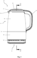
- a kettle 10 includes a base 12 and a hollow body 14.
- the hollow body 14 has a bottom wall 16 and a side wall 18 extending upwardly from the bottom wall 16 to a rim 19.
- the hollow body 14 also has a lid 20 to engage the rim 19.
- the hollow body 14 also includes a handle 24 attached to the side wall 18, and a spout 26 also attached to the side wall 18.
- the bottom wall 16, the side wall 18 and the lid 20 surround a cavity 22 to receive water to be heated. Further, the bottom wall 16 has a generally planar inner surface 17 facing the cavity 22. The inner surface 17 has an area that is substantially horizontal when the kettle 10 is resting on a surface.
- the hollow body 14 also includes a housing 28 fixed to the hollow body 14.
- the housing 28 is separated from the hollow body 14 by a sound-isolating layer or rubber mount 30, preferably made of a silicone rubber.
- the bottom wall 16 includes a heating element 32 that occupies a horizontal area as projected, for example, onto the inner surface 17 of the bottom wall 16.
- a heating element 32 that occupies a horizontal area as projected, for example, onto the inner surface 17 of the bottom wall 16.
- the heating element 32 is a resistive thin film transistor (TFT) element that forms substantially all of the bottom wall 16.
- TFT resistive thin film transistor
- the rubber mount 30 extends below the heating element 32.
- the rubber mount 30 also wraps around an edge 34 of the heating element 32 such that the heating element 32 does not contact the housing 28. Yet further, the rubber mount 30 extends a short distance above the heating element 32, inwardly from the edge 34 such that the heating element 32 also does not contact the side wall 18. That is, the rubber mount 30 has a shorter horizontal extent above the heating element 32 than below the heating element 34 to ensure efficient thermal communication between the heating element 32 and water contained in the cavity 22.
- the rubber mount 30 also extends parallel to the side wall 18 between the side wall 18 and the housing 28, such that the housing 28 does not contact the side wall 18.
- the housing 28 and the rubber mount 30 are adhesively fixed to the hollow body 14, for example at lower rounded corner 21 of the side wall 18.
- the housing 28 includes a first retainer 36 located below the rubber mount 30.
- the retainer 36 is attached to the housing 28 by a set of fasteners 38.
- a first sound-absorbing layer 40 is held between the rubber mount 30 and the retainer 36.
- the first sound-absorbing layer 40 is preferably a foam.
- the first sound-absorbing layer 40 includes an aperture 42 to allow access to the heating element 32. Located in the aperture 42 is a connector 44, the connector 44 includes a power cable (not shown) connected to the heating element 32.
- the housing further includes a floor 46 located below the retainer 36.
- the floor 46 is attached to the housing 28 by a set of fasteners 48.
- a second sound-absorbing layer 50 is held between the retainer 36 and the floor 46.
- the second sound-absorbing layer 50 is preferably a foam.
- the floor 46 includes a recess 52 above and around which is located a chamber 54.
- the chamber 54 houses an electrical power receiving module 56.
- the power receiving module 56 is adapted to receive a sensor signal from a sensor (not shown) via the connector and is also adapted to supply power to the heating element 32 via the power cable.
- the base 12 is adapted to receive the hollow body 14 and includes an upper surface 58.
- the upper surface 58 includes a location projection 60 adapted to be received in the recess 52, the projection 60 is a rotating electrical connector.
- Located in the base 12 is a power supply module 62 adapted to supply power to the power receiving module 56using the rotating electrical connector.
- the base 12 further includes, in this embodiment, seven buttons 64, though any number could be used, to receive instructions from a user and a controller (not shown).
- the buttons 64 are adapted to send a button signal to the controller.
- the first controller is adapted to operate the power supply module 62 in response to the button signal.
- the controller may also receive a sensor signal from the power receiving module 56. In response to that indication the controller is also adapted to control the supply of power to the power receiving module 56.
- the base 12 includes a set of rubber feet 66 upon which the kettle 10 rests when placed on a surface (not shown).
- the base 12 is connected to a power source (not shown), such as an outlet and the hollow body 14 is placed on the base 12.
- a power source not shown
- the projection 60 is located in the recess 52.
- the power supply module 62 is now able to supply power to the power receiving module 56.
- the controller When the buttons 64 are operated by a user to indicate that water in the cavity 22 should be heated, the controller operates the power supply module 62 to supply power to the receiving power module 56. The receiving power module 56 subsequently supplies power to the heating element 32.
- the heating element 32 is resistively heated and increases the temperature of the bottom wall 16 of the hollow body 14.
- the heat transfer density of the heating element 32 referring to the inner surface 17 of the bottom wall 16 is preferably between 0.1-0.4 W/mm 2 averaged in a, for example, 100 mm 2 region.
- the bottom wall 16 transfers hHeat is transferred from the heating element 32 to water contained in the cavity 22. As the water in the cavity 22 reaches its boiling point it starts to agitate.
- the sensor for example, provides the sensor signal to the controller indicating a water temperature. Once the water temperature reaches a pre-determined water temperature the controller ceases to supply power to the receiving power module 56.
- the horizontal area occupied by the heating element 32 is a substantial portion of the inner surface area 17. Therefore, the heat transfer from the heating element 32 to the water contained in the cavity 22 occurs over a large surface area, compared with tube heating elements that were previously discussed operating on the same household wattage.
- the kettle 10 substantially reduces the likelihood that water will be heated above its boiling point, thereby reducing the likelihood that a steam bubble will form. As fewer, or no, steam bubbles are formed, no steam bubbles exist that can cavitate, which reduces, or eliminates, the noise created by steam bubble cavitation.
- the rubber mount 30 also retains the heating element 32.
- the heating element 32 may vibrate when heated, due to the use of alternating current (AC).
- AC alternating current
- the retention of the heating element 32 by the rubber mount 30 absorbs a portion of and reduces the transmission of these vibrations to both the cavity 22, as well as the housing 28.
- the sound-absorbing foam layers 40, 50 absorb a portion of and reduce the vibrations and noise that may yet transfer through the rubber mount 30.
- the heating element 32, the sound-isolating rubber mount 30, and the sound-absorbing foam layers 40, 50 substantially reduce the noise produced by the kettle 10.
- the cross section of the heater element 32 may only overlap the cross section of the lower surface 16 by more than 70%, more than 50%, or even more than 30%.
- the heating element 32 could be a heating coil having a path and a width in the horizontal plane.
- the heating element 32 may be separate and extending in a parallel horizontal plane below, but adjacent and/or attached to the bottom wall 16.
- the heating element 32 may be separate and extending in a parallel horizontal plane below, and distanced by a gap from the bottom wall 16.
Landscapes
- Engineering & Computer Science (AREA)
- Food Science & Technology (AREA)
- Cookers (AREA)
Description
- This invention relates to a kettle.
- Kettles are well-known devices to rapidly boil water for, for example, making tea, cooking, or the like. A disadvantage of presently known kettles is that as water is heated by a heating element, a small quantity of water close to the heating element is heated to above its boiling point. The quantity of water changes phase to steam and collects as a steam bubble at a steam bubble initiation site, usually a surface imperfection. As the steam bubble has a lower density than water the steam bubble rises due to buoyancy. As the steam bubble rises, the temperature of the surrounding water is below boiling temperature, causing the steam bubble to also cool down below boiling temperature. As the steam bubble cavitates, significant sound waves are created. The noise caused by the cavitation is undesirable in a home environment. It is very difficult to spread the heat over a kettle surface of a tube heating element of the kind used in a variety of kettles. Therefore, water adjacent the tube heating element tends to heat up faster as opposed to water away from it creating an imbalance in temperature and magnifying the cavitation.
- Attempts have been made to design a kettle to avoid the formation of steam bubbles by subjecting the interior surface of the kettle to a surface treatment such that minimal, or no, surface imperfections exist. This approach eliminates the initiation sites for steam bubbles, which reduces the amount of bubbles formed, the amount of bubbles that cavitate and therefore the noise level. However, the surface finish is vulnerable to damage such as scratching etc. Yet further, following successive boiling cycles, water will leave behind a residue, which will then act as steam bubble initiation sites. Document
CN 105 725 776 A discloses a noise-reducing and purifying electric kettle comprising a kettle body, a detachable kettle bottom mounted at the bottom of the kettle body, and a heating base. The kettle bottom is hermetically connected with the kettle body. A porous heat-conducting medium is arranged between the kettle bottom and the kettle body. The lower surface of the porous heat-conducting medium is in full contact with a heat-conducting surface of the kettle bottom, and the upper surface of the porous heat-conducting medium is communicated with an inner cavity of the kettle body. - It is an object of the present invention to address the above discussed problem, or at least provide a useful alternative to the above-mentioned kettles.
- In a first aspect the present invention provides a kettle according to claim 1.
- Preferably, the horizontal area is in a plane below the bottom wall.
- Preferably, the inner surface is generally planar and the plane is parallel to the inner surface.
- Preferably, the plane is horizontal when the kettle is resting on a surface.
- Preferably, the inner surface is horizontal when the kettle is resting on a surface.
- Preferably, the housing is fixed to the hollow body by an adhesive located between the hollow body and the housing.
- Preferably, the adhesive bonded to the sound-isolating layer.
- Preferably, the heating element is retained by the sound-isolating layer such that a gap exists between the heating element and the bottom wall.
- Preferably, the sound-isolating layer is formed from rubber silicone.
- Preferably, the sound-absorbing layer is a foam.
- Preferably, the kettle further comprises:
- a base to receive the hollow body and the housing;
- a controller located in the base;
- a magnetic power supply located in the base; and
- a receiving power module located in the housing and connected to the heating element,
- wherein the magnetic power supply is configured to supply power to the receiving power module to supply power to the heating element.
- Preferably, the controller is operatively connected to the heating element using a power cable to supply power to the heating element, and a communication cable to receive sensor data from the heating element.
- Preferably, the base has a projection and the housing has a recess, the projection being locatable in the recess such that, when the projection is located in the recess, the magnetic power supply is aligned with receiving power module to supply power.
- Preferably, the heating element occupies a horizontal area that is at least 50% of the inner surface area.
- More preferably, the heating element occupies a horizontal area that is at least 70% of the area of the inner surface.
- Even more preferably, the heating element occupies a horizontal area that is at least 90% of the area of the inner surface.
- Preferably, the heat density provided by the heating element is between 0.1 to 0.4 W/mm2 in a 100 mm2 region.
- Preferably, the elastic rubber mount has a shorter horizontal extent above the heating element than below the heating element.
- Preferred embodiments of the present invention will now be described, by way of examples only, with reference to the accompanying drawings:
-
Fig. 1 is a perspective view of a kettle according to an embodiment of the present invention. -
Fig. 2 is a top plan view of the kettle ofFig. 1 . -
Fig. 3 is a front elevation view of the kettle ofFig. 1 . -
Fig. 4 is a section view along the axis D-D indicated onFig. 3 of the kettle ofFig. 1 . -
Fig. 5 is a partial section view of the kettle ofFig. 1 showing a TFT heating element used in the kettle ofFig. 1 . - As shown in
Fig. 1 , akettle 10 according to an embodiment of the present invention includes abase 12 and ahollow body 14. Thehollow body 14 has abottom wall 16 and aside wall 18 extending upwardly from thebottom wall 16 to arim 19. Thehollow body 14 also has alid 20 to engage therim 19. As best seen inFig. 3 , thehollow body 14 also includes ahandle 24 attached to theside wall 18, and aspout 26 also attached to theside wall 18. - As shown in
Fig. 4 , thebottom wall 16, theside wall 18 and thelid 20 surround acavity 22 to receive water to be heated. Further, thebottom wall 16 has a generally planarinner surface 17 facing thecavity 22. Theinner surface 17 has an area that is substantially horizontal when thekettle 10 is resting on a surface. - As further shown in
Fig. 4 , thehollow body 14 also includes ahousing 28 fixed to thehollow body 14. Thehousing 28 is separated from thehollow body 14 by a sound-isolating layer orrubber mount 30, preferably made of a silicone rubber. - The
bottom wall 16 includes aheating element 32 that occupies a horizontal area as projected, for example, onto theinner surface 17 of thebottom wall 16. For example, if theheating element 32 were a tube of 10 mm diameter and a horizontal length of 50 mm, it would occupy a horizontal area of 500 mm2. In the preferred embodiment theheating element 32 is a resistive thin film transistor (TFT) element that forms substantially all of thebottom wall 16. Theheating element 32 occupies a horizontal area as defined by the width and length of atrace 33, as shown inFig. 5 . - The
rubber mount 30 extends below theheating element 32. Therubber mount 30 also wraps around anedge 34 of theheating element 32 such that theheating element 32 does not contact thehousing 28. Yet further, therubber mount 30 extends a short distance above theheating element 32, inwardly from theedge 34 such that theheating element 32 also does not contact theside wall 18. That is, therubber mount 30 has a shorter horizontal extent above theheating element 32 than below theheating element 34 to ensure efficient thermal communication between theheating element 32 and water contained in thecavity 22. Therubber mount 30 also extends parallel to theside wall 18 between theside wall 18 and thehousing 28, such that thehousing 28 does not contact theside wall 18. Thehousing 28 and therubber mount 30 are adhesively fixed to thehollow body 14, for example at lowerrounded corner 21 of theside wall 18. - The
housing 28 includes afirst retainer 36 located below therubber mount 30. Theretainer 36 is attached to thehousing 28 by a set offasteners 38. A first sound-absorbinglayer 40 is held between therubber mount 30 and theretainer 36. The first sound-absorbinglayer 40 is preferably a foam. The first sound-absorbinglayer 40 includes anaperture 42 to allow access to theheating element 32. Located in theaperture 42 is aconnector 44, theconnector 44 includes a power cable (not shown) connected to theheating element 32. - The housing further includes a
floor 46 located below theretainer 36. Thefloor 46 is attached to thehousing 28 by a set offasteners 48. A second sound-absorbinglayer 50 is held between theretainer 36 and thefloor 46. The second sound-absorbinglayer 50 is preferably a foam. Thefloor 46 includes arecess 52 above and around which is located achamber 54. Thechamber 54 houses an electricalpower receiving module 56. Thepower receiving module 56 is adapted to receive a sensor signal from a sensor (not shown) via the connector and is also adapted to supply power to theheating element 32 via the power cable. - The
base 12 is adapted to receive thehollow body 14 and includes anupper surface 58. Theupper surface 58 includes alocation projection 60 adapted to be received in therecess 52, theprojection 60 is a rotating electrical connector. Located in thebase 12 is apower supply module 62 adapted to supply power to the power receiving module 56using the rotating electrical connector. The base 12 further includes, in this embodiment, sevenbuttons 64, though any number could be used, to receive instructions from a user and a controller (not shown). Thebuttons 64 are adapted to send a button signal to the controller. The first controller is adapted to operate thepower supply module 62 in response to the button signal. The controller may also receive a sensor signal from thepower receiving module 56. In response to that indication the controller is also adapted to control the supply of power to thepower receiving module 56. - Finally, the
base 12 includes a set ofrubber feet 66 upon which thekettle 10 rests when placed on a surface (not shown). - Use of the
kettle 10 will now be discussed. - The
base 12 is connected to a power source (not shown), such as an outlet and thehollow body 14 is placed on thebase 12. When placing thehollow body 14 on thebase 12, theprojection 60 is located in therecess 52. Thepower supply module 62 is now able to supply power to thepower receiving module 56. - When the
buttons 64 are operated by a user to indicate that water in thecavity 22 should be heated, the controller operates thepower supply module 62 to supply power to the receivingpower module 56. The receivingpower module 56 subsequently supplies power to theheating element 32. - The
heating element 32 is resistively heated and increases the temperature of thebottom wall 16 of thehollow body 14. The heat transfer density of theheating element 32, referring to theinner surface 17 of thebottom wall 16 is preferably between 0.1-0.4 W/mm2 averaged in a, for example, 100 mm2 region. Thebottom wall 16 transfers hHeat is transferred from theheating element 32 to water contained in thecavity 22. As the water in thecavity 22 reaches its boiling point it starts to agitate. - The sensor, for example, provides the sensor signal to the controller indicating a water temperature. Once the water temperature reaches a pre-determined water temperature the controller ceases to supply power to the receiving
power module 56. - Advantages of the
kettle 10 will now be discussed. - The horizontal area occupied by the
heating element 32 is a substantial portion of theinner surface area 17. Therefore, the heat transfer from theheating element 32 to the water contained in thecavity 22 occurs over a large surface area, compared with tube heating elements that were previously discussed operating on the same household wattage. By distributing the heat over a larger surface area thekettle 10 substantially reduces the likelihood that water will be heated above its boiling point, thereby reducing the likelihood that a steam bubble will form. As fewer, or no, steam bubbles are formed, no steam bubbles exist that can cavitate, which reduces, or eliminates, the noise created by steam bubble cavitation. - The
hollow body 14 rests substantially on the sound-isolatingrubber mount 30. As the water agitates close to its boiling point, the sound-isolatingrubber mount 30 absorbs a portion of and reduces transmission of the vibration to thehousing 28 and thebase 12. This arrangement reduces noise created by vibrations caused by the agitation of the water. - The
rubber mount 30 also retains theheating element 32. Theheating element 32 may vibrate when heated, due to the use of alternating current (AC). The retention of theheating element 32 by therubber mount 30 absorbs a portion of and reduces the transmission of these vibrations to both thecavity 22, as well as thehousing 28. - The sound-absorbing
foam layers rubber mount 30. - Together, the
heating element 32, the sound-isolatingrubber mount 30, and the sound-absorbingfoam layers kettle 10. - For example, the cross section of the
heater element 32 may only overlap the cross section of thelower surface 16 by more than 70%, more than 50%, or even more than 30%. - Yet further, the
heating element 32 could be a heating coil having a path and a width in the horizontal plane. - Yet further, the
heating element 32 may be separate and extending in a parallel horizontal plane below, but adjacent and/or attached to thebottom wall 16. - Yet further, the
heating element 32 may be separate and extending in a parallel horizontal plane below, and distanced by a gap from thebottom wall 16.
Claims (18)
- A kettle comprising:a hollow body (14) having a bottom wall (16) and a side wall (18) extending upwardly from the bottom wall (16) to a rim (19), with the side wall (18) surrounding a cavity (22) to receive water to be heated, the bottom wall (16) having an inner surface (17) facing the cavity (22), the inner surface (17) having an area;an elastic rubber mount (30);a housing (28) fixed to the hollow body (14); anda heating element (32) in thermal communication with the bottom wall (16) to thereby heat the water, wherein the elastic rubber mount (30) wraps around an edge (34) of the heating element (32) such that the heating element (32) does not contact the housing (28);wherein the elastic rubber mount (30) is located between the side wall (18) and the housing (28), and surrounds the bottom wall 16); andwherein the elastic rubber mount (30) comprises a sound-isolating layer, and the housing (28) further comprises a sound-absorbing layer (40) located below the sound-isolating layer;wherein the hollow body (4) rests on the elastic rubber mount (30); andwherein the heating element (32) occupies a horizontal area that is at least 30% of the area of the inner surface (17).
- The kettle of claim 1, wherein the horizontal area is in a plane below the bottom wall (16).
- The kettle of claim 2, wherein the inner surface (17) is generally planar and the plane is parallel to the inner surface (17).
- The kettle of claim 2, wherein the plane is horizontal when the kettle (10) is resting on a surface.
- The kettle of claim 1, wherein the inner surface (17) is horizontal when the kettle is resting on a surface.
- The kettle of claim 1, wherein the housing (28) is fixed to the hollow body (14) by an adhesive located between the hollow body (14) and the housing (28).
- The kettle of claim 6, wherein the adhesive is bonded to the sound-isolating layer.
- The kettle of claim 1, wherein the heating element (32) is retained by the sound-isolating layer such that a gap exists between the heating element (32) and the bottom wall (16).
- The kettle of claim 1, wherein the sound-isolating layer is formed from rubber silicone.
- The kettle of claim 1, wherein the sound-absorbing layer is a foam.
- The kettle of claim 1, wherein the kettle (10) further comprises:a base (12) to receive the hollow body (14) and the housing (28);a controller located in the base (12);a magnetic power supply located in the base (12); anda receiving power module (56) located in the housing (28) and connected to the heating element (32),wherein the magnetic power supply is configured to supply power to the receiving power module (56) to supply power to the heating element (32).
- The kettle of claim 11, wherein the controller is operatively connected to the heating element (32) using a power cable to supply power to the heating element (32), and a communication cable to receive sensor data from the heating element (32).
- The kettle of claim 12, wherein:
the base (12) has a projection (60) and the housing (28) has a recess (52), the projection (60) being locatable in the recess (52) such that, when the projection (60) is located in the recess (52), the magnetic power supply is aligned with receiving power module (56) to supply power. - The kettle of claim 1, wherein the heating element (32) occupies a horizontal area that is at least 50% of the area of the inner surface (17).
- The kettle of claim 1, wherein the heating element (32) occupies a horizontal area that is at least 70% of the area of the inner surface (17).
- The kettle of claim 1, wherein the heating element (32) occupies a horizontal area that is at least 90% of the area of the inner surface (17).
- The kettle of claim 1, wherein the heat density provided by the heating element (32) is between 0.1 to 0.4 W/mm2 in a 100 mm2 region.
- The kettle of claim 1, wherein the elastic rubber mount (30 has a shorter horizontal extent above the heating element (32) than below the heating element (32).
Applications Claiming Priority (2)
| Application Number | Priority Date | Filing Date | Title |
|---|---|---|---|
| AU2018904019A AU2018904019A0 (en) | 2018-10-23 | Kettle | |
| PCT/AU2019/051111 WO2020082111A1 (en) | 2018-10-23 | 2019-10-14 | Kettle |
Publications (3)
| Publication Number | Publication Date |
|---|---|
| EP3870004A1 EP3870004A1 (en) | 2021-09-01 |
| EP3870004A4 EP3870004A4 (en) | 2022-08-03 |
| EP3870004B1 true EP3870004B1 (en) | 2024-11-20 |
Family
ID=70330238
Family Applications (1)
| Application Number | Title | Priority Date | Filing Date |
|---|---|---|---|
| EP19875307.1A Active EP3870004B1 (en) | 2018-10-23 | 2019-10-14 | Kettle |
Country Status (5)
| Country | Link |
|---|---|
| US (1) | US20210378435A1 (en) |
| EP (1) | EP3870004B1 (en) |
| CN (1) | CN113163969B (en) |
| AU (1) | AU2019363541B2 (en) |
| WO (1) | WO2020082111A1 (en) |
Families Citing this family (5)
| Publication number | Priority date | Publication date | Assignee | Title |
|---|---|---|---|---|
| USD961982S1 (en) * | 2020-09-21 | 2022-08-30 | Ning Guo | Foldable electric kettle |
| USD985993S1 (en) * | 2021-07-07 | 2023-05-16 | The Steelstone Group Llc | Kettle |
| USD1019243S1 (en) * | 2021-12-08 | 2024-03-26 | The Steelstone Group Llc | Kettle |
| USD1041991S1 (en) * | 2023-03-31 | 2024-09-17 | Whirlpool Corporation | Electric kettle |
| USD1077558S1 (en) * | 2024-05-12 | 2025-06-03 | Shenzhen Intellirocks Tech. Co., Ltd. | Electric kettle with kettle base |
Family Cites Families (34)
| Publication number | Priority date | Publication date | Assignee | Title |
|---|---|---|---|---|
| GB9503256D0 (en) * | 1995-02-20 | 1995-04-12 | Pifco Ltd | Improvements to liquid boiling apparatus |
| JPH09201281A (en) * | 1996-01-30 | 1997-08-05 | Matsushita Electric Ind Co Ltd | Induction heating device |
| GB2322273B (en) * | 1997-02-17 | 2001-05-30 | Strix Ltd | Electric heaters |
| GB2353456B (en) * | 1999-08-13 | 2004-08-25 | Strix Ltd | Electric heaters |
| US6392206B1 (en) * | 2000-04-07 | 2002-05-21 | Waltow Polymer Technologies | Modular heat exchanger |
| US20060094285A1 (en) * | 2004-11-04 | 2006-05-04 | Panamax | Rotating electrical connector |
| US7166822B1 (en) * | 2005-11-22 | 2007-01-23 | Peter Chung-Yuan Chang | Cooking apparatus employing centrally located heat source |
| GB0624984D0 (en) * | 2006-12-14 | 2007-01-24 | Otter Controls Ltd | Electric water heater |
| EP2306870B1 (en) * | 2008-06-26 | 2013-05-29 | Breville PTY Limited | Kettle and base |
| US8076620B2 (en) * | 2008-11-07 | 2011-12-13 | Lance P. Johnson | Anti-oxidation food preparation device |
| CA2753852C (en) * | 2009-02-27 | 2014-05-06 | Momentive Specialty Chemicals Inc. | Compositions useful for non-cellulose fiber sizing, coating or binding compositions, and composites incorporating same |
| CN201468985U (en) * | 2009-05-11 | 2010-05-19 | 森泉企业股份有限公司 | Heating device for thermos bottle or water dispenser |
| GB0919913D0 (en) * | 2009-11-13 | 2009-12-30 | Mcwilliams Kevin | Product warming device |
| CN202234933U (en) * | 2010-05-13 | 2012-05-30 | 翱泰温控器(深圳)有限公司 | Cordless electric device and cordless power supply for same |
| US20120091119A1 (en) * | 2010-10-15 | 2012-04-19 | Adjo Designs Pty. Ltd. | Rotatable Vessel |
| US10010213B2 (en) * | 2010-11-02 | 2018-07-03 | Ember Technologies, Inc. | Heated or cooled dishware and drinkware and food containers |
| JP2012139447A (en) * | 2011-01-05 | 2012-07-26 | Tiger Vacuum Bottle Co Ltd | Electric kettle |
| CN102846196B (en) * | 2011-07-01 | 2016-12-28 | 皇家飞利浦电子股份有限公司 | For the sealing member used in electric-heating container |
| AU2012264402A1 (en) * | 2011-08-10 | 2014-03-20 | Strix Limited | Controls for a liquid heating apparatus |
| CN203059392U (en) * | 2013-01-31 | 2013-07-17 | 关荣发 | Sound-insulation barrel cover for water dispenser |
| JP6403314B2 (en) * | 2014-06-10 | 2018-10-10 | 株式会社テーケィアール | ELECTRIC INSULATION AND COOLING CONTAINER USING WIRELESS POWER TRANSFER, ELECTRIC INSULATION AND COOLING DEVICE USING THE SAME |
| CN204445425U (en) * | 2015-01-07 | 2015-07-08 | 浙江绍兴苏泊尔生活电器有限公司 | Soybean milk machine metal lower cover and soybean milk machine |
| CN105832143A (en) * | 2015-01-12 | 2016-08-10 | 广东美的生活电器制造有限公司 | Electric kettle |
| CN204363735U (en) * | 2015-01-12 | 2015-06-03 | 新疆鑫域森源机械设备有限公司 | The hot thermo jug body of a kind of quiet speed |
| CN106473595A (en) * | 2015-08-28 | 2017-03-08 | 广东美的生活电器制造有限公司 | Insulating pot |
| AU2015224376B2 (en) * | 2015-09-07 | 2021-08-05 | Newell Australia Pty Ltd | Heating vessel with noise reduction |
| CN205625604U (en) * | 2016-03-22 | 2016-10-12 | 慈溪市雪江电器厂 | Noise muting heating is fast's insulating pot |
| CN105725776A (en) * | 2016-04-28 | 2016-07-06 | 西安交通大学 | Noise-reducing and purifying electric kettle |
| CN206275564U (en) * | 2016-08-13 | 2017-06-27 | 泉州市联政信息科技有限公司 | A kind of Portable, environmental protective low noise fruit juice extractor |
| CN206576752U (en) * | 2016-12-03 | 2017-10-24 | 深圳市茶大师茶具电器有限公司 | A kind of damping noise-reducing structure |
| CN108652439B (en) * | 2017-03-31 | 2021-10-15 | 佛山市顺德区美的电热电器制造有限公司 | electric kettle |
| US10568460B2 (en) * | 2017-10-03 | 2020-02-25 | Lam & Sons, Llc | Portable electric grill having a domed lid and method of use |
| CN108670024B (en) * | 2018-04-25 | 2020-05-08 | 上海交通大学 | Overfill Immunity Contactless Power Transfer Kettle |
| CN213588038U (en) * | 2019-03-29 | 2021-07-02 | 布瑞威利私人有限公司 | Appliances for heating liquids |
-
2019
- 2019-10-14 US US17/288,014 patent/US20210378435A1/en not_active Abandoned
- 2019-10-14 CN CN201980078561.4A patent/CN113163969B/en active Active
- 2019-10-14 EP EP19875307.1A patent/EP3870004B1/en active Active
- 2019-10-14 WO PCT/AU2019/051111 patent/WO2020082111A1/en not_active Ceased
- 2019-10-14 AU AU2019363541A patent/AU2019363541B2/en active Active
Also Published As
| Publication number | Publication date |
|---|---|
| EP3870004A1 (en) | 2021-09-01 |
| CN113163969A (en) | 2021-07-23 |
| WO2020082111A1 (en) | 2020-04-30 |
| CN113163969B (en) | 2023-02-21 |
| US20210378435A1 (en) | 2021-12-09 |
| AU2019363541A1 (en) | 2021-06-03 |
| AU2019363541B2 (en) | 2025-10-02 |
| EP3870004A4 (en) | 2022-08-03 |
Similar Documents
| Publication | Publication Date | Title |
|---|---|---|
| EP3870004B1 (en) | Kettle | |
| CN213588038U (en) | Appliances for heating liquids | |
| KR101817780B1 (en) | Cooking vessel with supersonic vibrator | |
| RU2287915C2 (en) | Microwave oven with coffee maker and its control method | |
| CN113507871B (en) | induction kettle | |
| CN206026034U (en) | Electric kettle | |
| CN111000456B (en) | oven | |
| JP2791246B2 (en) | Induction heating rice cooker | |
| JPH09201281A (en) | Induction heating device | |
| JP2848280B2 (en) | Electromagnetic cooker | |
| JP3192922B2 (en) | an electronic pot | |
| JP2005024196A (en) | Built-in cooking device | |
| JP2004057227A (en) | Rice scoop | |
| JP2004290345A (en) | rice cooker | |
| CN210077360U (en) | cooking utensils | |
| JP2001292898A (en) | Combination hotwater-bath type keep-warm cooker and humidifier | |
| JP3102363B2 (en) | Electric rice cooker | |
| JP2001095679A (en) | Rice cooker | |
| CN107854000A (en) | A kind of Electromagnetic Heating utensil | |
| JPH08182617A (en) | Cooking auxiliary board and noodle boiler for microwave oven | |
| JP2011159552A (en) | Induction heating cooker | |
| JP3313262B2 (en) | pot | |
| JP2024007314A (en) | Cooking device | |
| JPH06284962A (en) | Rice cooking jar | |
| CN113134251A (en) | Container subassembly and cooking machine |
Legal Events
| Date | Code | Title | Description |
|---|---|---|---|
| STAA | Information on the status of an ep patent application or granted ep patent |
Free format text: STATUS: THE INTERNATIONAL PUBLICATION HAS BEEN MADE |
|
| PUAI | Public reference made under article 153(3) epc to a published international application that has entered the european phase |
Free format text: ORIGINAL CODE: 0009012 |
|
| STAA | Information on the status of an ep patent application or granted ep patent |
Free format text: STATUS: REQUEST FOR EXAMINATION WAS MADE |
|
| 17P | Request for examination filed |
Effective date: 20210510 |
|
| AK | Designated contracting states |
Kind code of ref document: A1 Designated state(s): AL AT BE BG CH CY CZ DE DK EE ES FI FR GB GR HR HU IE IS IT LI LT LU LV MC MK MT NL NO PL PT RO RS SE SI SK SM TR |
|
| DAV | Request for validation of the european patent (deleted) | ||
| DAX | Request for extension of the european patent (deleted) | ||
| A4 | Supplementary search report drawn up and despatched |
Effective date: 20220630 |
|
| RIC1 | Information provided on ipc code assigned before grant |
Ipc: A47J 27/21 20060101AFI20220624BHEP |
|
| TPAC | Observations filed by third parties |
Free format text: ORIGINAL CODE: EPIDOSNTIPA |
|
| GRAP | Despatch of communication of intention to grant a patent |
Free format text: ORIGINAL CODE: EPIDOSNIGR1 |
|
| STAA | Information on the status of an ep patent application or granted ep patent |
Free format text: STATUS: GRANT OF PATENT IS INTENDED |
|
| INTG | Intention to grant announced |
Effective date: 20240621 |
|
| GRAS | Grant fee paid |
Free format text: ORIGINAL CODE: EPIDOSNIGR3 |
|
| GRAA | (expected) grant |
Free format text: ORIGINAL CODE: 0009210 |
|
| STAA | Information on the status of an ep patent application or granted ep patent |
Free format text: STATUS: THE PATENT HAS BEEN GRANTED |
|
| AK | Designated contracting states |
Kind code of ref document: B1 Designated state(s): AL AT BE BG CH CY CZ DE DK EE ES FI FR GB GR HR HU IE IS IT LI LT LU LV MC MK MT NL NO PL PT RO RS SE SI SK SM TR |
|
| REG | Reference to a national code |
Ref country code: GB Ref legal event code: FG4D |
|
| REG | Reference to a national code |
Ref country code: CH Ref legal event code: EP |
|
| REG | Reference to a national code |
Ref country code: DE Ref legal event code: R096 Ref document number: 602019062390 Country of ref document: DE |
|
| REG | Reference to a national code |
Ref country code: IE Ref legal event code: FG4D |
|
| P01 | Opt-out of the competence of the unified patent court (upc) registered |
Free format text: CASE NUMBER: APP_61581/2024 Effective date: 20241118 |
|
| REG | Reference to a national code |
Ref country code: LT Ref legal event code: MG9D |
|
| REG | Reference to a national code |
Ref country code: NL Ref legal event code: MP Effective date: 20241120 |
|
| PG25 | Lapsed in a contracting state [announced via postgrant information from national office to epo] |
Ref country code: PT Free format text: LAPSE BECAUSE OF FAILURE TO SUBMIT A TRANSLATION OF THE DESCRIPTION OR TO PAY THE FEE WITHIN THE PRESCRIBED TIME-LIMIT Effective date: 20250320 Ref country code: HR Free format text: LAPSE BECAUSE OF FAILURE TO SUBMIT A TRANSLATION OF THE DESCRIPTION OR TO PAY THE FEE WITHIN THE PRESCRIBED TIME-LIMIT Effective date: 20241120 Ref country code: IS Free format text: LAPSE BECAUSE OF FAILURE TO SUBMIT A TRANSLATION OF THE DESCRIPTION OR TO PAY THE FEE WITHIN THE PRESCRIBED TIME-LIMIT Effective date: 20250320 |
|
| PG25 | Lapsed in a contracting state [announced via postgrant information from national office to epo] |
Ref country code: FI Free format text: LAPSE BECAUSE OF FAILURE TO SUBMIT A TRANSLATION OF THE DESCRIPTION OR TO PAY THE FEE WITHIN THE PRESCRIBED TIME-LIMIT Effective date: 20241120 Ref country code: NL Free format text: LAPSE BECAUSE OF FAILURE TO SUBMIT A TRANSLATION OF THE DESCRIPTION OR TO PAY THE FEE WITHIN THE PRESCRIBED TIME-LIMIT Effective date: 20241120 |
|
| REG | Reference to a national code |
Ref country code: AT Ref legal event code: MK05 Ref document number: 1742760 Country of ref document: AT Kind code of ref document: T Effective date: 20241120 |
|
| PG25 | Lapsed in a contracting state [announced via postgrant information from national office to epo] |
Ref country code: BG Free format text: LAPSE BECAUSE OF FAILURE TO SUBMIT A TRANSLATION OF THE DESCRIPTION OR TO PAY THE FEE WITHIN THE PRESCRIBED TIME-LIMIT Effective date: 20241120 |
|
| PG25 | Lapsed in a contracting state [announced via postgrant information from national office to epo] |
Ref country code: ES Free format text: LAPSE BECAUSE OF FAILURE TO SUBMIT A TRANSLATION OF THE DESCRIPTION OR TO PAY THE FEE WITHIN THE PRESCRIBED TIME-LIMIT Effective date: 20241120 |
|
| PG25 | Lapsed in a contracting state [announced via postgrant information from national office to epo] |
Ref country code: NO Free format text: LAPSE BECAUSE OF FAILURE TO SUBMIT A TRANSLATION OF THE DESCRIPTION OR TO PAY THE FEE WITHIN THE PRESCRIBED TIME-LIMIT Effective date: 20250220 |
|
| PG25 | Lapsed in a contracting state [announced via postgrant information from national office to epo] |
Ref country code: LV Free format text: LAPSE BECAUSE OF FAILURE TO SUBMIT A TRANSLATION OF THE DESCRIPTION OR TO PAY THE FEE WITHIN THE PRESCRIBED TIME-LIMIT Effective date: 20241120 Ref country code: GR Free format text: LAPSE BECAUSE OF FAILURE TO SUBMIT A TRANSLATION OF THE DESCRIPTION OR TO PAY THE FEE WITHIN THE PRESCRIBED TIME-LIMIT Effective date: 20250221 Ref country code: AT Free format text: LAPSE BECAUSE OF FAILURE TO SUBMIT A TRANSLATION OF THE DESCRIPTION OR TO PAY THE FEE WITHIN THE PRESCRIBED TIME-LIMIT Effective date: 20241120 |
|
| PG25 | Lapsed in a contracting state [announced via postgrant information from national office to epo] |
Ref country code: PL Free format text: LAPSE BECAUSE OF FAILURE TO SUBMIT A TRANSLATION OF THE DESCRIPTION OR TO PAY THE FEE WITHIN THE PRESCRIBED TIME-LIMIT Effective date: 20241120 |
|
| PG25 | Lapsed in a contracting state [announced via postgrant information from national office to epo] |
Ref country code: RS Free format text: LAPSE BECAUSE OF FAILURE TO SUBMIT A TRANSLATION OF THE DESCRIPTION OR TO PAY THE FEE WITHIN THE PRESCRIBED TIME-LIMIT Effective date: 20250220 |
|
| PG25 | Lapsed in a contracting state [announced via postgrant information from national office to epo] |
Ref country code: SM Free format text: LAPSE BECAUSE OF FAILURE TO SUBMIT A TRANSLATION OF THE DESCRIPTION OR TO PAY THE FEE WITHIN THE PRESCRIBED TIME-LIMIT Effective date: 20241120 |
|
| PG25 | Lapsed in a contracting state [announced via postgrant information from national office to epo] |
Ref country code: DK Free format text: LAPSE BECAUSE OF FAILURE TO SUBMIT A TRANSLATION OF THE DESCRIPTION OR TO PAY THE FEE WITHIN THE PRESCRIBED TIME-LIMIT Effective date: 20241120 |
|
| PG25 | Lapsed in a contracting state [announced via postgrant information from national office to epo] |
Ref country code: EE Free format text: LAPSE BECAUSE OF FAILURE TO SUBMIT A TRANSLATION OF THE DESCRIPTION OR TO PAY THE FEE WITHIN THE PRESCRIBED TIME-LIMIT Effective date: 20241120 |
|
| PG25 | Lapsed in a contracting state [announced via postgrant information from national office to epo] |
Ref country code: RO Free format text: LAPSE BECAUSE OF FAILURE TO SUBMIT A TRANSLATION OF THE DESCRIPTION OR TO PAY THE FEE WITHIN THE PRESCRIBED TIME-LIMIT Effective date: 20241120 |
|
| PG25 | Lapsed in a contracting state [announced via postgrant information from national office to epo] |
Ref country code: SK Free format text: LAPSE BECAUSE OF FAILURE TO SUBMIT A TRANSLATION OF THE DESCRIPTION OR TO PAY THE FEE WITHIN THE PRESCRIBED TIME-LIMIT Effective date: 20241120 |
|
| PG25 | Lapsed in a contracting state [announced via postgrant information from national office to epo] |
Ref country code: CZ Free format text: LAPSE BECAUSE OF FAILURE TO SUBMIT A TRANSLATION OF THE DESCRIPTION OR TO PAY THE FEE WITHIN THE PRESCRIBED TIME-LIMIT Effective date: 20241120 |
|
| PG25 | Lapsed in a contracting state [announced via postgrant information from national office to epo] |
Ref country code: IT Free format text: LAPSE BECAUSE OF FAILURE TO SUBMIT A TRANSLATION OF THE DESCRIPTION OR TO PAY THE FEE WITHIN THE PRESCRIBED TIME-LIMIT Effective date: 20241120 |
|
| REG | Reference to a national code |
Ref country code: DE Ref legal event code: R097 Ref document number: 602019062390 Country of ref document: DE |
|
| PG25 | Lapsed in a contracting state [announced via postgrant information from national office to epo] |
Ref country code: SE Free format text: LAPSE BECAUSE OF FAILURE TO SUBMIT A TRANSLATION OF THE DESCRIPTION OR TO PAY THE FEE WITHIN THE PRESCRIBED TIME-LIMIT Effective date: 20241120 |
|
| PLBE | No opposition filed within time limit |
Free format text: ORIGINAL CODE: 0009261 |
|
| STAA | Information on the status of an ep patent application or granted ep patent |
Free format text: STATUS: NO OPPOSITION FILED WITHIN TIME LIMIT |
|
| PGFP | Annual fee paid to national office [announced via postgrant information from national office to epo] |
Ref country code: GB Payment date: 20250904 Year of fee payment: 7 |
|
| PGFP | Annual fee paid to national office [announced via postgrant information from national office to epo] |
Ref country code: FR Payment date: 20250908 Year of fee payment: 7 |
|
| 26N | No opposition filed |
Effective date: 20250821 |
|
| PGFP | Annual fee paid to national office [announced via postgrant information from national office to epo] |
Ref country code: DE Payment date: 20250902 Year of fee payment: 7 |