EP3869848B1 - Gruppierung von verteilereinheiten einer basisstation - Google Patents
Gruppierung von verteilereinheiten einer basisstation Download PDFInfo
- Publication number
- EP3869848B1 EP3869848B1 EP19880502.0A EP19880502A EP3869848B1 EP 3869848 B1 EP3869848 B1 EP 3869848B1 EP 19880502 A EP19880502 A EP 19880502A EP 3869848 B1 EP3869848 B1 EP 3869848B1
- Authority
- EP
- European Patent Office
- Prior art keywords
- distributed unit
- specific
- identifier
- unit
- group
- Prior art date
- Legal status (The legal status is an assumption and is not a legal conclusion. Google has not performed a legal analysis and makes no representation as to the accuracy of the status listed.)
- Active
Links
Images


Classifications
-
- H—ELECTRICITY
- H04—ELECTRIC COMMUNICATION TECHNIQUE
- H04W—WIRELESS COMMUNICATION NETWORKS
- H04W4/00—Services specially adapted for wireless communication networks; Facilities therefor
- H04W4/06—Selective distribution of broadcast services, e.g. multimedia broadcast multicast service [MBMS]; Services to user groups; One-way selective calling services
- H04W4/08—User group management
-
- H—ELECTRICITY
- H04—ELECTRIC COMMUNICATION TECHNIQUE
- H04L—TRANSMISSION OF DIGITAL INFORMATION, e.g. TELEGRAPHIC COMMUNICATION
- H04L5/00—Arrangements affording multiple use of the transmission path
- H04L5/003—Arrangements for allocating sub-channels of the transmission path
- H04L5/0058—Allocation criteria
- H04L5/0073—Allocation arrangements that take into account other cell interferences
-
- H—ELECTRICITY
- H04—ELECTRIC COMMUNICATION TECHNIQUE
- H04W—WIRELESS COMMUNICATION NETWORKS
- H04W24/00—Supervisory, monitoring or testing arrangements
- H04W24/02—Arrangements for optimising operational condition
-
- H—ELECTRICITY
- H04—ELECTRIC COMMUNICATION TECHNIQUE
- H04B—TRANSMISSION
- H04B17/00—Monitoring; Testing
- H04B17/30—Monitoring; Testing of propagation channels
- H04B17/309—Measuring or estimating channel quality parameters
- H04B17/345—Interference values
-
- H—ELECTRICITY
- H04—ELECTRIC COMMUNICATION TECHNIQUE
- H04L—TRANSMISSION OF DIGITAL INFORMATION, e.g. TELEGRAPHIC COMMUNICATION
- H04L5/00—Arrangements affording multiple use of the transmission path
- H04L5/003—Arrangements for allocating sub-channels of the transmission path
- H04L5/0053—Allocation of signalling, i.e. of overhead other than pilot signals
-
- H—ELECTRICITY
- H04—ELECTRIC COMMUNICATION TECHNIQUE
- H04L—TRANSMISSION OF DIGITAL INFORMATION, e.g. TELEGRAPHIC COMMUNICATION
- H04L5/00—Arrangements affording multiple use of the transmission path
- H04L5/0091—Signalling for the administration of the divided path, e.g. signalling of configuration information
-
- H—ELECTRICITY
- H04—ELECTRIC COMMUNICATION TECHNIQUE
- H04W—WIRELESS COMMUNICATION NETWORKS
- H04W24/00—Supervisory, monitoring or testing arrangements
- H04W24/10—Scheduling measurement reports ; Arrangements for measurement reports
-
- H—ELECTRICITY
- H04—ELECTRIC COMMUNICATION TECHNIQUE
- H04W—WIRELESS COMMUNICATION NETWORKS
- H04W28/00—Network traffic management; Network resource management
- H04W28/16—Central resource management; Negotiation of resources or communication parameters, e.g. negotiating bandwidth or QoS [Quality of Service]
- H04W28/18—Negotiating wireless communication parameters
-
- H—ELECTRICITY
- H04—ELECTRIC COMMUNICATION TECHNIQUE
- H04W—WIRELESS COMMUNICATION NETWORKS
- H04W72/00—Local resource management
- H04W72/50—Allocation or scheduling criteria for wireless resources
- H04W72/54—Allocation or scheduling criteria for wireless resources based on quality criteria
- H04W72/542—Allocation or scheduling criteria for wireless resources based on quality criteria using measured or perceived quality
-
- H—ELECTRICITY
- H04—ELECTRIC COMMUNICATION TECHNIQUE
- H04W—WIRELESS COMMUNICATION NETWORKS
- H04W16/00—Network planning, e.g. coverage or traffic planning tools; Network deployment, e.g. resource partitioning or cells structures
- H04W16/18—Network planning tools
-
- H—ELECTRICITY
- H04—ELECTRIC COMMUNICATION TECHNIQUE
- H04W—WIRELESS COMMUNICATION NETWORKS
- H04W72/00—Local resource management
- H04W72/12—Wireless traffic scheduling
- H04W72/121—Wireless traffic scheduling for groups of terminals or users
-
- H—ELECTRICITY
- H04—ELECTRIC COMMUNICATION TECHNIQUE
- H04W—WIRELESS COMMUNICATION NETWORKS
- H04W88/00—Devices specially adapted for wireless communication networks, e.g. terminals, base stations or access point devices
- H04W88/08—Access point devices
- H04W88/085—Access point devices with remote components
Definitions
- This application relates to the field of communications technologies, and in particular, to a grouping method, for grouping at least one distribution unit, by a central unit of a base station and a controller.
- electromagnetic waves transmitted in the atmosphere are affected by atmospheric refraction, and propagation paths of the electromagnetic waves bend toward the ground.
- a curvature of the propagation path exceeds a surface curvature of the earth, a part of the electromagnetic waves are trapped in a thin atmospheric layer with a specific thickness.
- This phenomenon is similar to that electromagnetic waves are propagated in a waveguide, and is referred to as an atmospheric duct phenomenon. Due to an existence of the atmospheric duct phenomenon, a downlink signal sent by a base station in an area A may be propagated to an area B. A distance between the area B and the area A may be up to 300 kilometers.
- the downlink signal propagated from the area A to the area B causes interference to the uplink transmission performed by the base station in the area B.
- this interference is referred to as remote interference (remote interference, RI).
- the area A is an aggressor (aggressor) area
- the area B is a victim (victim) area.
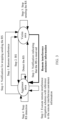
- a base station includes a central unit (central unit, CU) and at least one distributed unit (distributed unit, DU).
- a structure of the base station shown in FIG. 1 is used as an example.
- a remote interference management process is shown in FIG. 2 , and specifically includes the following steps. Step 1: A downlink signal sent by a DU in an aggressor (aggressor) area causes remote interference to receiving of an uplink signal by a DU of a base station in a victim (victim) area.
- Step 2 The DU of the base station in the victim area sends a reference signal (reference signal, RS) to the DU of a base station in the aggressor area through an air interface.
- Step 3 A CU of the base station in the aggressor area detects that the DU receives the RS, sends, to a CU of the base station in the victim area by using a backhaul network, a notification indicating that the RS is received, and executes remote interference mitigation schemes (remote interference mitigation schemes).
- RS reference signal
- Step 4 When detecting that the DU does not receive the RS within a long time, the CU of the base station in the aggressor area stops executing the remote interference mitigation schemes, stops RS detection, and sends, to the CU of the base station in the victim area, a notification for stopping sending the RS.
- Step 5 The CU of the base station in the victim area receives the notification for stopping sending the RS, and notifies the DU to stop sending the RS.
- the remote interference management process may alternatively be shown in FIG. 3 . A difference from the remote interference management process shown in FIG.
- the CU of the base station in the victim area sends remote interference assistance information to the CU of the base station in the aggressor area, to cooperate with the CU of the base station in the aggressor area to execute the remote interference mitigation schemes, thereby eliminating the remote interference.
- the document CN 101 448 306 A refers to a method for GSM circuit domain service station address selection, which is used for multi-station address co-district relay reversion.
- This application provides a grouping method, an apparatus, and a system, to help group distributed units, so that when being applied to a remote interference management process, embodiments of this application help reduce an amount of information processed by a CU, thereby improving performance of a base station.
- a grouping method as defined in claim 1 is provided. According to another aspect, another grouping method is provided as defined in claim 5. According to a further aspect, an embodiment of this application provides a central unit of a base station as defined in claim 8.
- an embodiment of this application provides a controller as defined in claim 9.
- At least one means one or more, and "a plurality of" means two or more.
- the term “and/or” describes an association relationship between associated objects and may indicate three relationships. For example, A and/or B may indicate the following cases: Only A exists, both A and B exist, and only B exists, where A and B may be singular or plural.
- the character “/” generally indicates an "or” relationship between associated objects.
- the term “at least one piece (item) of the following” or a similar expression thereof means any combination of these items, including any combination of a singular item (piece) or plural items (pieces).
- At least one (piece) of a, b, or c may indicate the following cases: a, b, c, a and b, a and c, b and c, or a, b, and c, where a, b, and c may be singular or plural.
- the embodiments of this application may be applied to, but are not limited to, a next-generation wireless communications (next radio, NR) system, or may be applied to a communications system such as a time division duplex long time evolution (time division duplexing long term evolution, TDD-LTE) system, or may be extended to a related cellular system such as a wireless fidelity (wireless fidelity, Wi-Fi) system, a worldwide interoperability for microwave access (worldwide interoperability for microwave access, wimax) system, a future wireless communications system, and a 3rd generation partnership project (3rd generation partnership project, 3GPP) system.
- a wireless fidelity wireless fidelity
- Wi-Fi worldwide interoperability for microwave access
- wimax worldwide interoperability for microwave access
- future wireless communications system a future wireless communications system
- 3rd generation partnership project 3rd generation partnership project
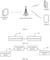
- a quantity of core network devices, a quantity of access network devices, and a quantity of terminals in the mobile communications system are not limited in the embodiments of this application.
- the communications system shown in FIG. 4 may further include other devices, such as a relay device and a backhaul device. This is also not limited in the embodiments of this application.
- functions of the core network device and functions of the access network device in the communications system shown in FIG. 4 may be separately integrated into mutually independent physical devices, or may be integrated into one physical device, or some functions of the core network device and some functions of the access network device may be integrated into one physical device.
- the terminal may be connected to the access network device in a wireless manner, and the access network device may be connected to the core network device in a wireless manner or a wired manner. It should be further noted that, the terminal in the communications system shown in FIG. 4 may be fixed or movable.
- the core network device in the embodiments of this application is configured to provide an access management function and a mobility management function.
- the core network device may be an access and mobility management function (access and mobility management function, AMF).
- AMF access and mobility management function
- the core network device may be a mobility management entity (mobility management entity, MME).
- the access network device in the embodiments of this application is configured to connect the terminal to a wireless network.
- the access network device may be referred to as a base station, or may be referred to as a radio access network (radio access network, RAN) node (or device).
- RAN radio access network
- the access network device may be a gNB, a transmission reception point (transmission reception point, TRP), an evolved NodeB (evolved Node B, eNB), a radio network controller (radio network controller, RNC), a NodeB (Node B, NB), a base station controller (base station controller, BSC), a base transceiver station (base transceiver station, BTS), a home base station (for example, a home evolved NodeB or a home Node B, HNB), a baseband unit (base band unit, BBU), or a wireless fidelity (wireless fidelity, Wi-Fi) access point (access point, AP).
- TRP transmission reception point
- eNB evolved NodeB
- RNC radio network controller
- NodeB Node B
- BSC base station controller
- BTS base transceiver station
- BTS home base station
- a home base station for example, a home evolved NodeB or a home Node B, HNB
- BBU
- the access network device includes a central unit (centralized unit, CU) and at least one distributed unit (distributed unit, DU).
- the CU may be configured to manage or control the at least one DU, in other words, the CU is connected to the at least one DU.
- protocol layers of the access network device in the communications system may be split. Apart of the protocol layers are controlled by the CU in a centralized manner, and functions of a part or all of remaining protocol layers are distributed in the DU.
- the CU controls the DU in a centralized manner.
- the access network device is a gNB.
- Protocol layers of the gNB include a radio resource control (radio resource control, RRC) layer, a service data adaptation protocol (service data adaptation protocol, SDAP) layer, a packet data convergence protocol (packet data convergence protocol, PDCP) layer, a radio link control (radio link control, RLC) layer, a media access control layer (media access control, MAC) layer, and a physical layer.
- RRC radio resource control
- SDAP service data adaptation protocol
- PDCP packet data convergence protocol
- RLC radio link control
- media access control layer media access control layer
- MAC media access control
- the CU is configured to implement functions of the RRC layer, the SDAP layer, and the PDCP layer
- the DU is configured to implement functions of the RLC layer, the MAC layer, and the physical layer.
- access network devices may directly communicate with each other.
- an access network device 501 and an access network device 502 directly communicate with each other.
- the access network device 501 and the access network device 502 may communicate with each other through an Xn interface.
- access network devices may alternatively communicate with each other by using a core network.
- FIG. 5b an access network device 503 and an access network device 504 communicate with each other by using a core network device 1 and a core network device 2.
- the core network device 1 is configured to manage the access network device 503, and the core network device 2 is configured to manage the access network device 504.
- the core network device 1 and the core network device 2 may be a same core network device, or may be different core network devices. Communication between the access network device 503 and the core network device 1 is used as an example.
- the access network device 503 may communicate with the core network device 1 through an NG interface, or may communicate with the core network device 1 in another manner.
- the terminal in the embodiments of this application may also be referred to as a terminal device, user equipment (user equipment, UE), a mobile station (mobile station, MS), a mobile terminal (mobile terminal, MT), or the like, and is a device that provides voice and/or data connectivity for a user.
- the terminal may be a handheld device that has a wireless connection function or a vehicle-mounted device.
- the terminal a mobile phone (mobile phone), a tablet computer, a laptop computer, a palmtop computer, a mobile internet device (mobile internet device, MID), a wearable device, a virtual reality (virtual reality, VR) device, an augmented reality (augmented reality, AR) device, a wireless terminal in industrial control (industrial control), a wireless terminal in self driving (self driving), a wireless terminal in remote medical surgery (remote medical surgery), a wireless terminal in a smart grid (smart grid), a wireless terminal in transportation safety (transportation safety), a wireless terminal in a smart city (smart city), a wireless terminal in a smart home (smart home), and the like.
- the gNB includes one CU and at least one DU. Degrees of remote interference suffered by different DUs may be different. To simplify remote interference management, in the embodiments of this application, the DUs may be grouped, and then the remote interference management is performed for different groups of DUs.
- the DU may report an interference intensity indication, so that the CU groups the DU. Then the CU sends a DU grouping status and the interference intensity indication to a controller.
- the controller may further group, based on the status of grouping the DU by the CU and the interference intensity indication, a DU in at least one gNB in a victim area again, to enable the CU to perform a remote interference management process for each DU group, thereby helping reduce an amount of processed information, and improving performance of a base station.
- the controller in the embodiments of this application may be a device, including an operation, administration and maintenance (operation, administration and maintenance, OAM) function, in a communications system, or may be a new device independently disposed in a communications system. Alternatively, a function of the controller may be integrated into an existing device (such as a core network device) in a communications system, or the like. This is not limited herein.
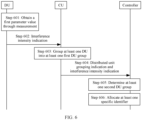
- Embodiment 1 of this application may be shown in FIG. 6 , and the grouping method includes the following steps:
- Step 601 The DU obtains a first parameter value through measurement, where the first parameter value is used to indicate an intensity of interference suffered by the DU.
- the DU may periodically obtain the first parameter value through measurement, or may obtain the first parameter value through measurement based on a configuration performed by the CU or the controller.
- a periodicity in which the DU obtains the first parameter value through measurement may be a frame, a subframe, a symbol, or the like, or may be preset duration. This is not limited herein.
- the first parameter value may be an interference over thermal (interference over thermal, loT), or may be another physical quantity, for example, a bit error rate, that can be used to indicate a degree of the interference suffered by the DU.
- the first parameter value is used to indicate an intensity of the remote interference suffered by the DU.
- the first parameter value is used to indicate an intensity of the other interference suffered by the DU.
- a type of the interference suffered by the DU is not limited in this embodiment of this application.
- Step 602 The DU reports the interference intensity indication to the CU, where the interference intensity indication is determined based on the first parameter value.
- the interference intensity indication may be the first parameter value, a value obtained after the first parameter value is quantized, an interference level corresponding to the first parameter, or the like.
- a quantizing policy may be preset. The DU determines the interference intensity indication according to the preset quantizing policy and based on the first parameter value.
- the value obtained after the quantizing may be from 0 to 1.
- the quantizing policy may be uniform quantizing or nonuniform quantizing.
- the first parameter value is the loT value.
- the preset quantizing policy is that: When the IoT value is (30, 40], a corresponding value obtained after the quantizing is 0.5, when the IoT value is (40, 50], a corresponding value obtained after the quantizing is 0.6, and so on. In this case, when the IoT value is 35, the interference intensity indication is 0.5.
- the interference intensity indication is the interference level corresponding to the first parameter value
- a correspondence between an intensity of remote interference suffered by the DU and an interference level may be preset.
- the interference level may include two levels (level), or may include four levels, or may include more levels. This is not limited herein.
- each level may be indicated by using one bit.
- an interference level is indicated by using 1, and the other interference level is indicated by using 0.
- each level may be indicated by using two bits. For example, 00, 01, 10, and 11 are separately used to indicate an interference level.
- the interference level may alternatively be high (High), medium (Medium), or low (Low). Specifically, a correspondence between the first parameter value and each of the high interference level, the medium interference level, and the low interference level may be preset.
- the DU may report the interference intensity indication to the CU in an event-triggered manner, or may periodically report the interference intensity indication.
- the DU When the DU reports the interference intensity indication to the CU in the event-triggered manner, when a first parameter value obtained through measurement in an i th periodicity is greater than a first threshold, the DU may report an interference intensity indication in the i th periodicity to the CU. In this case, if all first parameter values obtained through measurement by the DU before the i th periodicity are less than or equal to the first threshold, the DU may not report the interference intensity indication to the CU.
- i is a positive integer.
- the DU reports the interference intensity indication in the i th periodicity
- a difference between a first parameter value obtained through measurement in a j th periodicity and the first parameter value obtained through measurement in the i th periodicity is greater than a second threshold, or if a first parameter value obtained through measurement in a j th periodicity is less than a third threshold
- the DU reports an interference intensity indication in the j th periodicity to the CU.
- j is a positive integer greater than i.
- the first threshold and the third threshold may be the same, or may be different.
- the interference intensity indication, reported to the CU, in the j th periodicity may indicate that an intensity of interference suffered by the DU is 0, or interference suffered by the DU is eliminated.
- a periodicity in which the DU reports the interference intensity indication and a periodicity in which the DU obtains the first parameter value through measurement may be the same, or may be different. This is not limited herein.
- the DU may report the interference intensity indication to the CU after obtaining the first parameter value through periodic measurement, or the DU may report the interference intensity indication to the CU after obtaining a plurality of first parameter values through measurement.
- the DU may determine the interference intensity indication based on the plurality of first parameter values, or may determine the interference intensity indication based on a first parameter value obtained through latest measurement.
- the DU may report a first message carrying the interference intensity indication to the CU.
- the first message may be an existing message, or may be a newly defined message. It should be noted that, the DU may report the first message to the CU through an F1 interface.
- a step in which a DU reports a first message to a CU may be defined in a communications protocol.
- the step, in which the DU reports the first message to the CU defined in the communications protocol may be a new class 2 element procedure.
- the newly defined class 2 element procedure may be referred to as a remote interference management IoT indication procedure (RIM IoT Indication procedure), where the first message may be a RIM IOT INDICATION message (message).
- RIM IoT Indication procedure remote interference management IoT indication procedure
- the new class 2 element procedure may be defined by defining Table 1 in the communications protocol. Table 1 Elementary procedure Message RIM IoT Indication RIM IOT INDICATION
- the RIM IOT INDICATION message includes at least an interference intensity indication.
- the interference intensity indication is an information element or an element (IE) included in the RIM IOT INDICATION message.
- the interference intensity indication may also be referred to as an IoT information IE.
- a name of the interference intensity indication is not limited in this embodiment of this application.
- the IoT information IE is reported by the DU in the gNB to the CU, and the IoT information IE is an information element that needs to be included in the RIM IOT INDICATION message. That the RIM IOT INDICATION message includes at least the IoT information IE may be defined by defining Table 2 in the communications protocol. Table 2 IE/Group name Presence IoT information M
- Presence is M indicates that the RIM IOT INDICATION message needs to include the IoT information IE.
- Step 603 The CU receives an interference intensity indication reported by at least one DU, and groups the at least one DU into at least one first DU group based on the interference intensity indication reported by the at least one DU.
- the CU may receive the interference intensity indication reported by the at least one DU in the following manners:
- the CU After receiving the first interference intensity indication, the CU starts a timing clock, and receives the interference intensity indication reported by the DU. After the timing clock expires, the CU groups the at least one DU into the at least one first DU group based on the interference intensity indication, received within duration specified for the timing clock, reported by the at least one DU. For example, the CU may further suspend receiving an interference intensity indication after the timing clock ends. After receiving the first interference intensity indication again, the CU may restart the timing clock, and receive the interference intensity indication reported by the DU, to update DU grouping.
- the CU may alternatively periodically receive the interference intensity indication reported by the at least one DU.
- the periodicity in which the CU receives the interference intensity indication may be preset, or may be determined based on a preset algorithm. For example, if duration of the periodicity is one minute, the CU may group the at least one DU into the at least one first DU group based on an interference intensity indication, received within one minute, reported by the at least one DU.
- a DU may report a plurality of interference intensity indications within the specified duration.
- the CU may group the DU based on a latest interference intensity indication reported by the DU within the specified duration, to help improve reliability of the grouping.
- the specified duration is 4:00 to 4:01
- the gNB includes a DU 1, a DU 2, and a DU 3.
- the DU 3 reports an interference intensity indication to the CU at 4:00:05, reports an interference intensity indication to the CU at 4:00:15, and reports an interference intensity indication to the CU at 4:00:50.
- an interference intensity indication used for the DU 3 is the interference intensity indication reported by the DU 3 at 4:00:50.
- the CU may group DUs whose interference intensity indications are the same or similar into one group. For example, when an interference intensity is a value obtained after the first parameter value is quantized, DUs are grouped into one group, where a difference between interference intensity indications of the DUs is less than a specified threshold.
- the threshold may be correspondingly set based on a requirement of an actual status. For example, when the interference intensity indication is between 0 and 1, the threshold may be set to 0.01, 0.005, or the like.
- the CU may alternatively group the at least one DU into the at least one first DU group based on the interference intensity indication reported by the at least one DU and with reference to a historical interference intensity indication report record. In this way, DUs that suffer similar interference are grouped into one group. It should be noted that, the interference intensity indication that is received by the CU and that is reported by the at least one DU is currently received, and the historical interference intensity indication report record is reported before the at least one DU reports the interference intensity indication.
- the historical interference intensity indication report record may include an interference intensity indication that is used by the CU to group the DU for the last time.
- the CU may alternatively group the at least one DU into the at least one first DU group based on only the historical interference intensity indication report record or with reference to the historical interference intensity indication report record. For example, when the DU controlled by the CU receives a notification of an RS, the CU groups the at least one DU into the at least one first DU group based on the historical interference intensity indication report record of the DU.
- the historical interference intensity indication report record may include an interference intensity indication that is used by the CU to group the DU for the last time.
- the CU may perform interference management based on the obtained at least one first DU group, or may report a DU grouping status to the controller, and the controller further groups DUs in a plurality of gNBs. For example, when the CU reports the DU grouping status to the controller, the controller further groups the DUs in the plurality of gNBs. For details, refer to step 604 to step 606.
- Step 604 The CU sends, to the controller, a distributed unit grouping indication and an interference intensity indication that corresponds to the at least one first DU group.
- the distributed unit grouping indication is used to indicate the at least one first DU group.
- the interference intensity indication that is sent by the CU to the controller and that corresponds to the at least one first DU group is an interference intensity indication corresponding to each of the at least one first DU group, or may be an interference intensity indication of each DU included in each DU group.
- the CU groups the at least one DU into a first DU group 1, a first DU group 2, and a first DU group 3.
- the first DU group 1 includes a DU 0 and a DU 1
- the first DU group 2 includes a DU 2
- the first DU group 3 includes a DU 3 and a DU 4.
- an interference intensity indication corresponding to the first DU group 1 may be an interference intensity indication of the DU 0, an interference intensity indication of the DU 1, or an interference signal intensity indication obtained after a preset operation is performed on the interference intensity indication of the DU 0 and the interference intensity indication of the DU 1.
- a manner of the preset operation is not limited in this embodiment of this application.
- the preset operation may be a weighted average algorithm.
- Step 605 The controller receives the distributed unit grouping indication and the interference intensity indication that corresponds to the at least one first DU group that are reported by the at least one CU, and determines at least one second DU group based on the distributed unit grouping indication and the interference intensity indication that corresponds to the at least one first DU group that are reported by the at least one CU.
- Step 606 The controller allocates at least one specific identifier, where each of the at least one specific identifier is used to identify a second DU group.
- DUs in a plurality of different gNBs are grouped.
- the remote interference management process is performed for each DU group, thereby helping reduce an amount of information processed by the CU and improve device performance.
- the controller receives a distributed unit grouping indication 1, an interference intensity indication corresponding to a first DU group 1 connected to a CU 1, and a first DU group 2 connected to the CU 1 that are reported by the CU 1, a distributed unit grouping indication 2, an interference intensity indication corresponding to a first DU group 1 connected to a CU 2, and a first DU group 2 connected to the CU 2 that are reported by the CU 2.
- the distributed unit grouping indication 1 is used to indicate the first DU group 1 and the first DU group 2 that are connected to the CU 1
- the distributed unit grouping indication 2 is used to indicate the first DU group 1 and the first DU group 2 that are connected to the CU 2.
- the interference intensity indication corresponding to the first DU group 1 connected to the CU 1 is similar to or the same as the interference intensity indication corresponding to the first DU group 1 connected to the CU 2, the first DU group 1 connected to the CU 1 and the first DU group 1 connected to the CU 2 are aggregated to a second DU group 1. If the interference intensity indication corresponding to the first DU group 2 connected to the CU 1 is different from the interference intensity indication corresponding to the first DU group 2 connected to the CU 2, the first DU group 2 connected to the CU 1 is a second DU group 2, and the first DU group 2 connected to the CU 2 is a second DU group 3.
- the controller separately allocates a specific identifier 1 to the second DU group 1, allocates a specific identifier 2 to the second DU group 2, and allocates a specific identifier 3 to the second DU group 3.
- the specific identifier 1 is used to identify the second DU group 1
- the specific identifier 2 is used to identify the second DU group 2
- the specific identifier 3 is used to identify the second DU group 3.
- At least one second DU group determined by the controller may be the at least one first DU group.
- the controller receives a distributed unit grouping indication 0, an interference intensity indication corresponding to a DU 1 group, and an interference intensity indication corresponding to a DU 2 group that are reported by a CU 0, the controller determines that the DU 1 group is a second DU group a, and the DU 2 group is a second DU group b.
- the controller separately allocates a specific identifier a to the second DU group a, and allocates a specific identifier b to the second DU group b.
- the specific identifier a is used to identify the second DU group a
- the specific identifier b is used to identify the second DU group b.
- the specific identifier may also be referred to as a set identifier (set ID), a DU group identifier, a DU cluster identifier, or the like.
- set ID set identifier
- DU group identifier a DU cluster identifier
- a name of the specific identifier is not limited in this embodiment of this application.
- the controller further establishes an identifier relationship matching table for each specific identifier.
- the identifier relationship matching table includes a correspondence between a specific identifier and an identifier of a DU, and/or a correspondence between a specific identifier and an identifier of a CU.
- a specific identifier 1 is used to identify a second DU group 1.
- the second DU group 1 includes a DU 1, a DU 2, a DU 3, a DU 4, a DU 5, and a DU 6.
- a CU 1 is configured to manage or control the DU 1 and the DU 2
- a CU 2 is configured to manage or control the DU 3, the DU 4, and the DU 6,
- a CU 3 is configured to manage or control the DU 5. It may alternatively be understood that, the CU 1, the DU 1, and the DU 2 belong to one gNB, the CU 2, the DU 3, the DU 4, and the DU 6 belong to one gNB, and the CU 3 and the DU 5 belong to one gNB.
- an identifier relationship matching table established by the controller for the specific identifier 1 may be shown in Table 3.
- Table 3 Specific identifier 1 Identifier of the DU 1 Identifier of the DU 2 Identifier of the DU 3 Identifier of the DU 4 Identifier of the DU 5 Identifier of the DU 6
- an identifier relationship matching table established by the controller for the specific identifier 1 may alternatively be shown in Table 4.
- Table 4 Specific identifier 1 Identifier of the CU 1 Identifier of the CU 2 Identifier of the CU 3
- an identifier relationship matching table established by the controller for the specific identifier 1 may alternatively be shown in Table 5.
- Table 5 Specific identifier 1 Identifier of the DU 1 Identifier of the CU 1 Identifier of the DU 2 Identifier of the DU 3 Identifier of the CU 3 Identifier of the DU 4 Identifier of the DU 6 Identifier of the DU 5 Identifier of the CU 3
- the controller may further determine, for each of at least one specific identifier allocated for a second DU group, a specific CU in at least one CU configured to manage a DU included in the second DU group.
- the specific CU is configured to perform information exchange with an aggressor in the remote interference management process.
- the specific identifier 0 is used to identify a second DU group 0.
- the second DU group 0 includes a DU 1, a DU 2, a DU 3, a DU 4, a DU 5, a DU 6, a DU 7, a DU 8, and a DU 9.
- a CU 1 is configured to manage or control the DU 1 and the DU 2
- a CU 2 is configured to manage or control the DU 3, the DU 4, and the DU 6,
- a CU 3 is configured to manage or control the DU 5, the DU 7, the DU 8, and the DU 9.
- the controller determines a specific CU in the CU 1, the CU 2, and the CU 3 for the specific identifier 0, to perform information exchange with an aggressor in a remote interference management process.
- the specific CU is configured to manage a largest quantity of distributed units.
- the specific identity 0 as an example, the specific CU is the CU 3 in the CU 1, the CU 2, and the CU 3.
- the specific CU may alternatively be configured to manage a DU that suffers interference with a greatest intensity.
- the specific CU when there are at least two CUs, configured to manage a largest quantity of DUs, in the CU 1, the CU 2, and the CU 3, a CU configured to manage a DU that suffers interference with a greatest intensity is determined in the at least two CUs configured to manage the largest quantity of DUs as the specific CU.
- the specific CU may alternatively be determined in another manner. It should be noted that, the specific CU may also be referred to as a cluster head or another name. This is not limited herein.
- the controller may further send the specific identifier to the specific CU, so that the specific CU determines that DU grouping is completed, and the remote interference management process can be performed.
- the specific CU may further send the specific identifier to another CU configured to manage the DU in the second DU group identified by the specific identifier, so that the another CU can learn that the remote interference management process is initiated.
- the specific CU sends a remote interference management process end indication to the another CU configured to manage the DU in the second DU group identified by the specific identifier, so that the another CU can determine that the interference management process ends.
- the controller may further send the identifier relationship matching table to the specific CU.
- the specific CU is the CU 3.
- the controller sends the specific identifier 1 to the CU 3, and the CU 3 sends the specific identifier to the CU 1 and the CU 2.
- the controller may alternatively send the specific identifier to each CU configured to manage the second DU group identified by the specific identifier.
- the CU may read, by using the specific identifier, the identifier relationship matching table established in the controller, to determine whether the CU is the specific CU. Using Table 5 as an example, the controller sends the specific identifier 1 to the CU 1, the CU 2, and the CU 3.
- the controller may further send the identifier relationship matching table to each CU that corresponds to the second DU group.
- the controller may alternatively send the specific identifier to the DU included in the second DU group identified by the specific identifier.
- the DU sends the specific identifier to the CU that manages the DU.
- the CU may further read, based on the specific identifier, the identifier relationship matching table established in the controller, to determine whether the CU is the specific CU.
- the controller may alternatively send the specific identifier 1 to at least one of the DU 1 and the DU 2, at least one of the DU 3, the DU 4, and the DU 6, and the DU 6.
- the DU receiving the specific identifier 1 sends the specific identifier to a CU managing the DU.
- the DU 1 receives the specific identifier 1, and sends the specific identifier 1 to the CU 1.
- the controller may further send the identifier relationship matching table to the specific CU or each CU that corresponds to the second DU group.
- the CU determines that the controller completes the DU grouping. In this case, when the CU is the specific CU, the CU may initiate the remote interference management process. When the CU is not the specific CU, the CU determines that the specific CU may initiate the remote interference management process. In some embodiments, the controller does not update the identifier relationship matching table in the remote interference management process, to help reduce a possibility that an error occurs in remote interference management.
- the CU when the CU receives the at least one specific identifier, the CU sends, to the at least one DU, a notification for suspending the report of the interference intensity indication.
- a notification for suspending the report of the interference intensity indication when the CU 1 receives the specific identifier 1, the CU 1 sends, to the DU 1 and the DU 2, the notification for suspending the report of the interference intensity indication.
- the DU 1 and the DU 2 suspend measurement of the first parameter value, or suspend the report of the interference intensity indication to the CU 1.
- the controller may alternatively send, to the at least one DU, a notification for suspending the report of the interference intensity indication.
- the DU may suspend measurement of the first parameter value, or suspend the report of the interference intensity indication to the CU 1.
- the CU after determining that the remote interference management process ends, the CU sends, to the DU, a notification for reporting the interference intensity indication, so that the DU can restart to obtain the first parameter value through measurement, or report the interference intensity indication to the CU again.
- the CU determines that the remote interference management process ends.
- the CU determines that the remote interference management process ends.
- the controller may alternatively send, to the DU based on a preconfigured policy, a notification for reporting the interference intensity indication, so that the DU can start to obtain the first parameter value through measurement.
- the controller may periodically send or send in an event-triggered manner, to the DU, the notification for reporting the interference intensity indication.
- the CU does not control the DU to report the interference intensity indication.
- the CU may not perform an operation for grouping the DU, or may not report the distributed unit grouping indication to the controller, or may not perform another operation. Therefore, the controller cannot update the identifier relationship matching table in a process of performing the remote interference management process.
- a DU may report an interference intensity indication to a controller, to group the DU, so that a CU performs a remote interference management process for each DU group, thereby helping reduce an amount of processed information, and improving performance of a base station. It should be noted that, for a specific implementation of the controller in this embodiment of this application, refer to the specific implementation in Embodiment 1 of this application.
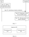
- Step 701 The DU obtains a first parameter value through measurement, where the first parameter value indicates an intensity of interference suffered by the DU.
- step 701 refers to the specific implementation of step 601 in Embodiment 1.
- Step 702 The DU reports the interference intensity indication to the controller, where the interference intensity indication is determined based on the first parameter value.
- the DU may report the interference intensity indication to the controller by using the CU, or may directly report the interference intensity indication to the controller.
- the DU reports the interference intensity indication to the controller by using the CU
- a manner in which the DU reports the interference intensity indication to the CU refer to the manner in which the DU reports the interference intensity indication to the CU in Embodiment 1.
- Step 703 After receiving an interference intensity indication reported by at least one DU, the controller groups the at least one DU into at least one DU group based on the interference intensity indication reported by the at least one DU.
- the interference intensity indication that is reported by the at least one DU and that is received by the controller may be interference intensity indications reported by DUs in different gNBs, so that the controller can group the DUs in the different gNBs.
- the controller groups the at least one DU into the at least one DU group based on the interference intensity indication reported by the DU refer to the manner of grouping the at least one DU into the at least one first DU group in Embodiment 1.
- Step 704 The controller allocates a specific identifier to each of the at least one DU group, where the specific identifier is used to identify a DU group, and DU groups identified by different specific identifiers are different.
- step 704 in Embodiment 2 of this application refer to the related descriptions of step 606 in Embodiment 1.
- each DU included in a DU group identified by a first specific identifier is notified to send a reference signal (for example, an RS).
- a reference signal for example, an RS.
- An identifier of the first specific CU is associated with the DU group identified by the first specific identifier.
- the reference signal includes the first specific identifier.
- the second specific CU After a second specific CU in an aggressor area detects a reference signal sent by a first DU, the second specific CU sends a first message to the first specific CU based on the first specific identifier.
- the first message includes a second specific identifier.
- the second specific identifier is used to indicate a DU group associated with an identifier of the second specific CU.
- the first DU is a DU included in the DU group identified by the first specific identifier.
- the first specific identifier may be associated with the identifier of the first specific CU.
- the second specific CU may obtain the identifier of the first specific CU from the controller based on the first specific identifier.
- the first message may further include a notification, sent by a CU in an aggressor area to a CU in a victim area, indicating that an RS is received in step 3 in a remote interference management process shown in FIG. 2 or FIG. 3 .
- the first message may be an existing message, or may be a newly defined message.
- the first specific CU may directly send the first message to the second specific CU.
- the first specific CU may send the first message to the second specific CU through an Xn interface.
- the first specific CU may alternatively send the first message to the second specific CU by using a core network.
- the first specific CU may send the first message to a core network device 1 (for example, an AMF 1) through an NG interface, then the core network device 1 sends the first message to a core network device 2 (for example, an AMF 2), and finally the core network device 2 forwards the first message to the second specific CU through an NG interface.
- a core network device 1 for example, an AMF 1
- a core network device 2 for example, an AMF 2
- the newly defined message may be defined by defining a new class 2 element procedure in a communications protocol.
- a step in which a CU sends a first message to an AMF may be defined as a RIM Information Indication procedure
- a step in which the AMF forwards the first message to the CU may be defined as a RIM Information Transfer procedure.
- the first message transmitted in the RIM Information Indication procedure may be referred to as a RIM INFORMATION INDICATION message
- the first message forwarded in the RIM Information Transfer procedure may be referred to as a RIM INFORMATION TRANSFER message.
- the new class 2 element procedure may be defined by defining Table 6 in the communications protocol.
- Table 6 Elementary procedure Message RIM Information Indication RIM INFORMATION INDICATION RIM Information Transfer RIM INFORMATION TRANSFER
- the RIM INFORMATION INDICATION message and the RIM INFORMATION TRANSFER message include at least the second specific identifier.
- the second specific identifier is an information element included in the RIM INFORMATION INDICATION message and the RIM INFORMATION TRANSFER message.
- the second specific identifier may also be referred to as an Aggressor set ID IE.
- the second specific identifier is not included in the first message sent by the specific CU in the aggressor area to the CU in the victim area in step 3 shown in FIG. 2 or FIG.
- the RIM INFORMATION INDICATION message and the RIM INFORMATION TRANSFER message are messages sent in another step, that the RIM INFORMATION INDICATION message and the RIM INFORMATION TRANSFER message include the Aggressor set ID IE is not necessary.
- the RIM INFORMATION INDICATION message includes the Aggressor set ID IE is not necessary may be defined by defining Table 7 in the communications protocol. Table 7 IE/Group name Presence Aggressor set ID O
- Presence is O indicates that that the RIM INFORMATION INDICATION message includes the Aggressor set ID IE is optional.
- the RIM INFORMATION TRANSFER message includes the Aggressor set ID IE is not necessary may be defined by defining Table 8 in the communications protocol.
- Presence is O indicates that that the RIM INFORMATION TRANSFER message includes the Aggressor set ID IE is optional.
- Embodiment 1 and Embodiment 2 of this application related descriptions are provided from a perspective of a base station in the victim (victim) area.
- a base station in the aggressor (aggress) area for manners of grouping a DU, allocating a specific identifier, sending the specific identifier, establishing an identifier relationship matching table, determining a specific CU, and so on, refer to the related descriptions in Embodiment 1 and Embodiment 2 of this application.
- the gNB may perform interference measurement, and report an interference intensity indication to a controller.
- the controller groups at least one gNB reporting an interference intensity indication.
- the gNB performs interference measurement refer to the manner in which the DU obtains the first parameter value through measurement in the foregoing embodiments.
- the gNB reports the interference intensity indication refer to the manner in which the DU reports the interference intensity indication in the foregoing embodiments.
- the controller groups the gNB refer to the manner in which the controller groups the DU.
- a corresponding device for example, a distributed unit, a central unit, or a controller
- a corresponding device may include a hardware structure and/or a software module, and implement the foregoing functions in a form of the hardware structure, the software module, or a combination of the hardware structure and the software module.
- Whether a specific function of the foregoing functions is performed by the hardware structure, the software module, or the combination of the hardware structure and the software module depends on a specific application and a design constraint of the technical solution.
- FIG. 8 is a schematic structural diagram of an apparatus 800 according to an embodiment of this application.
- the apparatus 800 includes a transceiver unit 820 and a processing unit 810.
- the processing unit 810 when the apparatus is configured to perform the steps performed by the DU in the grouping method shown in FIG. 6 or FIG. 7 , the processing unit 810 is configured to perform step 601 or step 701, and the transceiver unit 820 is configured to perform step 602 or step 702. In some embodiments, when the apparatus is configured to perform the steps performed by the controller in the grouping method shown in FIG. 6 or FIG. 7 , the processing unit 810 is configured to perform step 605 and step 606, or step 703 and step 704, and the transceiver unit 820 is configured to perform step 604 or step 702. In some embodiments, when the apparatus is configured to perform the steps performed by the CU in the grouping method shown in FIG. 6 , the processing unit 810 is configured to perform step 603, and the transceiver unit 820 is configured to perform step 602 and step 604.
- the apparatus 800 may be a chip, or may be a device.
- a hardware implementation of the processing unit 810 may be a processor
- a hardware implementation of the transceiver unit 820 may be a transceiver.
- FIG. 9 is a schematic structural diagram of another apparatus 900 according to an embodiment of this application.
- the apparatus 900 may include a processor 910, a transceiver 920, and a memory 930.
- the transceiver 920 is configured to receive and send information, and may include a receiver and a transmitter.
- the memory 930 may be configured to store a program/code that is pre-installed when the apparatus 900 is delivered from a factory, or store code executed by the processor 910, or the like.
- the processor 910 is configured to execute, in combination with the transceiver 920, the program/code stored in the storage 930, to implement the grouping method in the embodiments of this application.
- the processor 910 may be an integrated circuit chip and has a signal processing capability.
- the processor 910 may be a general-purpose processor, a digital signal processor (digital signal processor, DSP), an application-specific integrated circuit (application specific integrated circuit, ASIC), a field programmable gate array (field programmable gate array, FPGA) or another programmable logic component, a discrete gate or a transistor logic device, or a discrete hardware component.
- DSP digital signal processor
- ASIC application specific integrated circuit
- FPGA field programmable gate array
- the processor 910 may implement or perform the methods, steps, and logical block diagrams that are disclosed in the embodiments of this application.
- the general-purpose processor may be a microprocessor, any conventional processor, or the like.
- the steps of the method disclosed with reference to the embodiments of this application may be directly executed and completed by a hardware decoding processor, or may be executed and completed by using a combination of hardware and a software module in the decoding processor.
- the software module may be located in a mature storage medium in the art, such as a random access memory, a flash memory, a read-only memory, a programmable read-only memory, an electrically erasable programmable memory, or a register.
- the storage medium is located in the memory, and the processor reads information in the memory, and completes the steps in the foregoing methods in combination with hardware of the processor.
- the memory 930 in this embodiment of this application may be a volatile memory or a nonvolatile memory, or may include both a volatile memory and a nonvolatile memory.
- the nonvolatile memory may be a read-only memory (read-only memory, ROM), a programmable read-only memory (programmable ROM, PROM), an erasable programmable read-only memory (erasable PROM, EPROM), an electrically erasable programmable read-only memory (electrically EPROM, EEPROM), or a flash memory.
- the volatile memory may be a random access memory (random access memory, RAM), and is used as an external cache.
- RAMs may be used, for example, a static random access memory (static RAM, SRAM), a dynamic random access memory (dynamic RAM, DRAM), a synchronous dynamic random access memory (synchronous DRAM, SDRAM), a double data rate synchronous dynamic random access memory (double data rate SDRAM, DDR SDRAM), an enhanced synchronous dynamic random access memory (enhanced SDRAM, ESDRAM), a synchlink dynamic random access memory (synchlink DRAM, SLDRAM), and a direct rambus random access memory (direct rambus RAM, DR RAM).
- static random access memory static random access memory
- DRAM dynamic random access memory
- DRAM dynamic random access memory
- SDRAM synchronous dynamic random access memory
- double data rate SDRAM double data rate SDRAM
- DDR SDRAM double data rate SDRAM
- ESDRAM enhanced synchronous dynamic random access memory
- synchlink dynamic random access memory synchlink dynamic random access memory
- direct rambus RAM direct rambus RAM
- the apparatus 900 further includes another component required for implementing normal running.
- the apparatus 900 may further include a hardware component implementing another additional function.
- the apparatus 900 may alternatively include only components or modules necessary for implementing this embodiment of this application, and does not need to include all the components shown in FIG. 9 .
- the apparatus 900 in this embodiment of this application may be configured to perform the steps performed by the distributed unit in the grouping method shown in FIG. 6 or FIG. 7 , or may be configured to perform the steps performed by the controller in the grouping method shown in FIG. 6 or FIG. 7 , or may be configured to perform the steps performed by the central unit in the grouping method shown in FIG. 6 .
- a person of ordinary skill in the art may understand that all or some of the processes of the methods in the embodiments may be implemented by a computer program instructing relevant hardware.
- the program may be stored in a computer-readable storage medium. When the program runs, the processes of the embodiments of the methods are included.
- the foregoing storage medium may be a magnetic disk, an optical disk, a ROM, a RAM, or the like.
- An embodiment of this application further provides a computer program product.
- the computer program product is executed by a computer, the method according to any one of the method embodiments is implemented.
- An embodiment of this application further provides a communications system.
- the communications system includes the apparatus 800 or the apparatus 900.
- the apparatus 800 and the apparatus 900 may be configured to implement the grouping method in the embodiments of this application.
- the apparatus 800 and the apparatus 900 may be configured to implement the grouping method in the embodiments of this application.
- the embodiments of this application may be implemented by using hardware, firmware, or a combination thereof.
- the foregoing functions may be stored in a computer-readable medium or transmitted as one or more instructions or code in a computer-readable medium.
- the computer-readable medium includes a computer storage medium and a communications medium, where the communications medium includes any medium that enables a computer program to be transmitted from one place to another.
- the storage medium may be any available medium that can be accessed by a computer.
- the computer-readable medium may include, but is not limited to, a RAM, a ROM, an electrically erasable programmable read-only memory (electrically erasable programmable read only memory, EEPROM), a compact disc read-only memory (compact disc read-only memory, CD-ROM) or another compact disc storage, a magnetic disk storage medium or another magnetic storage device, or any other medium that can be configured to carry or store desired program code in a form of an instruction or a data structure and that can be accessed by a computer.
- any connection may be appropriately defined as the computer-readable medium.
- the software is transmitted from a website, a server, or another remote source by using a coaxial cable, an optical fiber/cable, a twisted pair, a digital subscriber line (digital subscriber line, DSL), or a wireless technology such as infrared, radio, or microwave
- the coaxial cable, the optical fiber/cable, the twisted pair, the DSL, or the wireless technology such as infrared, radio, or microwave are included in a definition of a medium to which the coaxial cable, the optical fiber/cable, the twisted pair, the DSL, or the wireless technology such as infrared ray, radio, or microwave belongs.
- a disk (disk) and a disc (disc) that are used in the embodiments of this application include a compact disc (compact disc, CD), a laser disc, an optical disc, a digital versatile disc (digital video disc, DVD), a floppy disk, and a Blu-ray disc.
- the disk usually magnetically copies data, and the disc optically copies data in a laser manner.
- the foregoing combination shall also be included in the protection scope of the computer-readable medium.
Landscapes
- Engineering & Computer Science (AREA)
- Signal Processing (AREA)
- Computer Networks & Wireless Communication (AREA)
- Quality & Reliability (AREA)
- Physics & Mathematics (AREA)
- Electromagnetism (AREA)
- Multimedia (AREA)
- Mobile Radio Communication Systems (AREA)
Claims (9)
- Gruppierungsverfahren, das durch eine zentrale Einheit einer Basisstation durchgeführt wird, wobei die Basisstation die zentrale Einheit und mindestens eine verteilte Einheit umfasst, wobei jede verteilte Einheit aus der mindestens einen verteilten Einheit separat mit der zentralen Einheit verbunden ist, wobei das Verfahren die folgenden Schritte umfasst:Empfangen (Schritt 602) einer Interferenzintensitätsanzeige, die durch die mindestens eine verteilte Einheit berichtet wird,Gruppieren (Schritt 603) der mindestens einen verteilten Einheit in mindestens eine erste verteilte Einheitsgruppe basierend auf der durch die mindestens eine verteilte Einheit berichteten Interferenzintensitätsanzeige, undSenden (Schritt 604), an eine Steuerung in einem System, das die Steuerung und die Basisstation umfasst, einer verteilten Einheitsgruppierungsanzeige und einer Interferenzintensitätsanzeige, die der mindestens einen ersten verteilten Einheitsgruppe entspricht, wobei die verteilte Einheitsgruppierungsanzeige verwendet wird, um die mindestens eine erste verteilte Einheitsgruppe anzuzeigen.
- Verfahren nach Anspruch 1, wobei das Gruppieren (Schritt 603) der mindestens einen verteilten Einheit in mindestens eine erste verteilte Einheitsgruppe basierend auf der durch die mindestens eine verteilte Einheit berichteten Interferenzintensitätsanzeige Folgendes umfasst:
Gruppieren der mindestens einen verteilten Einheit in die mindestens eine erste verteilte Einheitsgruppe basierend auf der durch die mindestens eine verteilte Einheit berichteten Interferenzintensitätsanzeige und einer historischen Interferenzintensitätsanzeigeberichtsaufzeichnung. - Verfahren nach Anspruch 1 oder 2, wobei das Verfahren ferner Folgendes umfasst:
Empfangen mindestens einer spezifischen Kennung von der Steuerung, wobei: jede der mindestens einen spezifischen Kennung verwendet wird, um eine zweite verteilte Einheitsgruppe zu kennzeichnen, und zweite verteilte Einheitsgruppen, die durch unterschiedliche spezifische Kennungen gekennzeichnet sind, unterschiedlich sind, wobei mindestens eine zweite verteilte Einheitsgruppe durch die Steuerung basierend auf der verteilten Einheitsgruppierungsanzeige und der Interferenzintensitätsanzeige bestimmt wird, die durch jede mindestens einer zentralen Einheit, die mindestens die zentrale Einheit umfasst, gesendet werden. - Verfahren nach Anspruch 3, wobei eine spezifische Kennung aus der mindestens einen spezifischen Kennung mit einer Kennung der zentralen Einheit assoziiert wird.
- Gruppierungsverfahren, das durch eine Steuerung in einem System durchgeführt wird, wobei das System die Steuerung und N Basisstationen umfasst, wobei jede Basisstation aus den N Basisstationen eine zentrale Einheit aus N zentralen Einheiten und mindestens eine verteilte Einheit umfasst, wobei jede verteilte Einheit aus der mindestens einen verteilten Einheit separat mit der zentralen Einheit der entsprechenden Basisstation verbunden ist, wobei das Verfahren Folgendes umfasst:Empfangen (Schritt 604), von jeder zentralen Einheit aus den N zentralen Einheiten, einer verteilten Einheitsgruppierungsanzeige und einer Interferenzintensitätsanzeige, die mindestens einer ersten verteilten Einheitsgruppe entspricht, wobei N eine positive Ganzzahl ist,wobei die verteilte Einheitsgruppierungsanzeige verwendet wird, um die mindestens eine erste verteilte Einheitsgruppe anzuzeigen, in die die mindestens eine verteilte Einheit der einen Basisstation aus den N Basisstationen, die die verteilte Einheitsgruppierungsanzeige und die Interferenzintensitätsanzeige an die Steuerung gesendet hat, gruppiert wird,Bestimmen (Schritt 605) von M zweiten verteilten Einheitsgruppen basierend auf der verteilten Einheitsgruppierungsanzeige und der Interferenzintensitätsanzeige, die von jeder zentralen Einheit aus den N zentralen Einheiten empfangen werden, wobei M eine positive Ganzzahl ist, undZuweisen (Schritt 606) von M spezifischen Kennungen, wobei eine Eins-zu-Eins-Entsprechung zwischen den M spezifischen Kennungen und den M zweiten verteilten Einheitsgruppen besteht, so dass jede spezifische Kennung aus den M spezifischen Kennungen verwendet wird, um eine unterschiedliche zweite verteilte Einheitsgruppe aus den M zweiten verteilten Einheitsgruppen zu kennzeichnen.
- Verfahren nach Anspruch 5, wobei das Verfahren ferner Folgendes umfasst:Senden, für eine erste spezifische Kennung aus den M spezifischen Kennungen, der ersten spezifischen Kennung an mindestens eine der N zentralen Einheiten, wobei die mindestens eine der N zentralen Einheiten dazu konfiguriert ist, eine verteilte Einheit zu verwalten, die in einer zweiten verteilten Einheitsgruppe aus den M zweiten verteilten Einheitsgruppen enthalten ist, die durch die erste spezifische Kennung gekennzeichnet ist, wobei die erste spezifische Kennung eine beliebige der M spezifischen Kennungen ist, oderSenden, für die erste spezifische Kennung in den M spezifischen Kennungen, der ersten spezifischen Kennung an eine verteilte Einheit, die in einer zweiten verteilten Einheitsgruppe aus den M zweiten verteilten Einheitsgruppen enthalten ist, die durch die erste spezifische Kennung gekennzeichnet ist, wobei die erste spezifische Kennung eine beliebige der M spezifischen Kennungen ist.
- Verfahren nach Anspruch 5 oder 6, wobei das Verfahren ferner Folgendes umfasst:
Erstellen einer Kennungsbeziehungszuordnungstabelle für jede der M spezifischen Kennungen, wobei die Kennungsbeziehungszuordnungstabelle eine Entsprechung zwischen einer spezifischen Kennung aus den M spezifischen Kennungen und mindestens einer Kennung einer verteilten Einheit aus den verteilten Einheiten der mindestens einen Basisstation und/oder eine Entsprechung zwischen der spezifischen Kennung und einer Kennung mindestens einer zentralen Einheit aus den N zentralen Einheiten umfasst. - Zentrale Einheit einer Basisstation, wobei die Basisstation die zentrale Einheit und mindestens eine verteilte Einheit umfasst, wobei jede verteilte Einheit aus der mindestens einen verteilten Einheit separat mit der zentralen Einheit verbunden ist, wobei die zentrale Einheit dazu konfiguriert ist, ein beliebiges der Verfahren nach den Ansprüchen 1-4 durchzuführen.
- Steuerung in einem System, wobei das System die Steuerung und N Basisstationen umfasst, wobei jede Basisstation aus den N Basisstationen eine zentrale Einheit und mindestens eine verteilte Einheit umfasst, wobei jede verteilte Einheit aus der mindestens einen verteilten Einheit separat mit der zentralen Einheit der entsprechenden Basisstation verbunden ist, wobei die Steuerung dazu konfiguriert ist, ein beliebiges der Verfahren nach den Ansprüchen 5-7 durchzuführen.
Applications Claiming Priority (2)
| Application Number | Priority Date | Filing Date | Title |
|---|---|---|---|
| CN201811303756.8A CN111148126B (zh) | 2018-11-02 | 2018-11-02 | 一种分组方法、装置及系统 |
| PCT/CN2019/114874 WO2020088616A1 (zh) | 2018-11-02 | 2019-10-31 | 一种分组方法、装置及系统 |
Publications (3)
| Publication Number | Publication Date |
|---|---|
| EP3869848A1 EP3869848A1 (de) | 2021-08-25 |
| EP3869848A4 EP3869848A4 (de) | 2021-12-29 |
| EP3869848B1 true EP3869848B1 (de) | 2024-04-24 |
Family
ID=70464618
Family Applications (1)
| Application Number | Title | Priority Date | Filing Date |
|---|---|---|---|
| EP19880502.0A Active EP3869848B1 (de) | 2018-11-02 | 2019-10-31 | Gruppierung von verteilereinheiten einer basisstation |
Country Status (5)
| Country | Link |
|---|---|
| US (1) | US11838833B2 (de) |
| EP (1) | EP3869848B1 (de) |
| KR (1) | KR20210080539A (de) |
| CN (1) | CN111148126B (de) |
| WO (1) | WO2020088616A1 (de) |
Families Citing this family (8)
| Publication number | Priority date | Publication date | Assignee | Title |
|---|---|---|---|---|
| EP3923503A4 (de) | 2019-03-12 | 2022-04-27 | Huawei Technologies Co., Ltd. | Entferntes interferenzverwaltungsverfahren und -gerät |
| CN111698068B (zh) * | 2019-03-12 | 2022-02-18 | 华为技术有限公司 | 一种远程干扰管理方法及装置 |
| CN111756492B (zh) * | 2019-03-28 | 2022-07-22 | 中国移动通信有限公司研究院 | 一种处理方法及设备 |
| US11917440B2 (en) | 2020-09-28 | 2024-02-27 | Qualcomm Incorporated | CU-DU signaling to report cross-link interference measurements |
| CN112243261B (zh) | 2020-10-10 | 2021-09-14 | 中兴通讯股份有限公司 | 信息反馈、接收方法、装置、设备和存储介质 |
| JP2025511500A (ja) * | 2022-08-04 | 2025-04-16 | 楽天シンフォニー株式会社 | 共有通信環境における通信デバイスのキャリア設定及び監視 |
| US12408074B2 (en) | 2022-12-02 | 2025-09-02 | Electronics And Telecommunications Research Institute | Method and apparatus of data transmission for high capacity network |
| KR102841742B1 (ko) * | 2022-12-02 | 2025-08-01 | 한국전자통신연구원 | 대용량 전송 네트워크를 위한 데이터 전송 방법 및 장치 |
Family Cites Families (11)
| Publication number | Priority date | Publication date | Assignee | Title |
|---|---|---|---|---|
| CN101448306A (zh) * | 2008-12-26 | 2009-06-03 | 华为技术有限公司 | Gsm电路域选择服务站址的方法、系统及射频拉远单元 |
| WO2011113192A1 (zh) * | 2010-03-15 | 2011-09-22 | 上海贝尔股份有限公司 | 用于消减小区间下行干扰的分布式资源分配方法及装置 |
| KR20150115015A (ko) | 2013-02-07 | 2015-10-13 | 인터디지탈 패튼 홀딩스, 인크 | 방향성 메시 네트워크에서의 간섭 측정 및 관리 |
| CN107484183B (zh) * | 2016-06-08 | 2020-12-29 | 中国移动通信有限公司研究院 | 一种分布式基站系统、cu、du及数据传输方法 |
| US9985808B2 (en) * | 2016-07-07 | 2018-05-29 | Qualcomm Incorporated | Methods and apparatus for managing interference across operators |
| KR102100491B1 (ko) * | 2016-07-13 | 2020-04-14 | 주식회사 케이티 | 프론트홀 인터페이스를 이용한 중앙 유닛 구성 방법 및 그 장치 |
| US10542556B2 (en) * | 2016-09-23 | 2020-01-21 | Qualcomm Incorporated | Modulation and coding scheme (MCS) and/or rank selection in coordinated multi-point (CoMP) communication |
| WO2018053852A1 (zh) * | 2016-09-26 | 2018-03-29 | 北京小米移动软件有限公司 | 无线承载的配置方法、装置及系统 |
| CN108616933A (zh) * | 2017-01-24 | 2018-10-02 | 电信科学技术研究院 | 一种中央单元-分布式单元架构下的通信处理方法及装置 |
| CN108039903B (zh) * | 2017-09-11 | 2021-06-01 | 华为技术有限公司 | 一种通信方法及设备 |
| CN111756507B (zh) * | 2019-03-29 | 2021-10-22 | 成都华为技术有限公司 | 一种远程干扰管理方法及装置 |
-
2018
- 2018-11-02 CN CN201811303756.8A patent/CN111148126B/zh active Active
-
2019
- 2019-10-31 EP EP19880502.0A patent/EP3869848B1/de active Active
- 2019-10-31 KR KR1020217016181A patent/KR20210080539A/ko not_active Abandoned
- 2019-10-31 WO PCT/CN2019/114874 patent/WO2020088616A1/zh not_active Ceased
-
2021
- 2021-04-29 US US17/244,340 patent/US11838833B2/en active Active
Also Published As
| Publication number | Publication date |
|---|---|
| US20210250735A1 (en) | 2021-08-12 |
| EP3869848A1 (de) | 2021-08-25 |
| EP3869848A4 (de) | 2021-12-29 |
| US11838833B2 (en) | 2023-12-05 |
| KR20210080539A (ko) | 2021-06-30 |
| WO2020088616A1 (zh) | 2020-05-07 |
| CN111148126B (zh) | 2022-04-05 |
| CN111148126A (zh) | 2020-05-12 |
Similar Documents
| Publication | Publication Date | Title |
|---|---|---|
| EP3869848B1 (de) | Gruppierung von verteilereinheiten einer basisstation | |
| KR102404125B1 (ko) | 실패 처리 방법, 스위칭 방법, 단말 디바이스, 및 네트워크 디바이스 | |
| US11184886B2 (en) | Method, base station, and user equipment for implementing carrier aggregation | |
| US9681339B2 (en) | Security processing method and system in network handover process | |
| US11197246B2 (en) | Power control enhancements for multi-hop integrated access and backhaul | |
| US11234185B2 (en) | Cell identifier format per area in wireless network | |
| US20220053452A1 (en) | Communication method, communications apparatus, and communications system | |
| US20250048197A1 (en) | Method and System for Performing Fast Mobility Based On Lower Layer Signaling | |
| US12133286B2 (en) | Method and apparatus for identifying user equipment capability in sidelink transmission | |
| US20190364539A1 (en) | Data transmission processing method, user equipment, and base station | |
| US12184352B2 (en) | Atmospheric duct interference elimamating scheme | |
| US20250048206A1 (en) | Method and System for Cell Measurements and Measurement Report In Fast Mobility Based on Lower Layer Signaling | |
| US20240250730A1 (en) | Reporting method, equipment, and medium | |
| US11638222B2 (en) | Power determining method and apparatus | |
| EP3923503A1 (de) | Entferntes interferenzverwaltungsverfahren und -gerät | |
| US20230015705A1 (en) | Communication method, apparatus, and system | |
| US20250260482A1 (en) | Method, terminal device, and network device for communication | |
| WO2021032007A1 (zh) | 链路失败报告传输的方法和装置 | |
| WO2019024901A1 (zh) | 一种资源分配方法及装置 | |
| KR20190043079A (ko) | 네트워크에서 하향링크 데이터를 알리는 방법, 네트워크 트리거된 서비스 요청 방법, 그리고 이를 수행하는 네트워크 엔터티 | |
| US20230262536A1 (en) | Methods, apparatuses, computer programs and computer program products for user plane integrity protection during x2 handover | |
| WO2020199938A1 (zh) | 一种远程干扰管理方法及装置 | |
| KR20250121436A (ko) | 무선 통신 방법, 단말 장치 및 네트워크 장치 | |
| US12245107B2 (en) | Communication apparatus and method of V2X services and communication system | |
| AU2022426545B2 (en) | Coordination method and device for service transmission |
Legal Events
| Date | Code | Title | Description |
|---|---|---|---|
| STAA | Information on the status of an ep patent application or granted ep patent |
Free format text: STATUS: THE INTERNATIONAL PUBLICATION HAS BEEN MADE |
|
| PUAI | Public reference made under article 153(3) epc to a published international application that has entered the european phase |
Free format text: ORIGINAL CODE: 0009012 |
|
| STAA | Information on the status of an ep patent application or granted ep patent |
Free format text: STATUS: REQUEST FOR EXAMINATION WAS MADE |
|
| 17P | Request for examination filed |
Effective date: 20210518 |
|
| AK | Designated contracting states |
Kind code of ref document: A1 Designated state(s): AL AT BE BG CH CY CZ DE DK EE ES FI FR GB GR HR HU IE IS IT LI LT LU LV MC MK MT NL NO PL PT RO RS SE SI SK SM TR |
|
| A4 | Supplementary search report drawn up and despatched |
Effective date: 20211129 |
|
| RIC1 | Information provided on ipc code assigned before grant |
Ipc: H04W 24/10 20090101ALN20211123BHEP Ipc: H04W 28/18 20090101ALI20211123BHEP Ipc: H04W 24/02 20090101ALI20211123BHEP Ipc: H04W 16/18 20090101AFI20211123BHEP |
|
| DAV | Request for validation of the european patent (deleted) | ||
| DAX | Request for extension of the european patent (deleted) | ||
| REG | Reference to a national code |
Ref country code: DE Free format text: PREVIOUS MAIN CLASS: H04W0016180000 Ref country code: DE Ref legal event code: R079 Ref document number: 602019051096 Country of ref document: DE Free format text: PREVIOUS MAIN CLASS: H04W0016180000 Ipc: H04B0017345000 |
|
| GRAP | Despatch of communication of intention to grant a patent |
Free format text: ORIGINAL CODE: EPIDOSNIGR1 |
|
| STAA | Information on the status of an ep patent application or granted ep patent |
Free format text: STATUS: GRANT OF PATENT IS INTENDED |
|
| RIC1 | Information provided on ipc code assigned before grant |
Ipc: H04W 88/08 20090101ALN20230601BHEP Ipc: H04W 72/121 20230101ALN20230601BHEP Ipc: H04W 24/10 20090101ALN20230601BHEP Ipc: H04W 72/542 20230101ALI20230601BHEP Ipc: H04W 4/08 20090101ALI20230601BHEP Ipc: H04L 5/00 20060101ALI20230601BHEP Ipc: H04W 24/02 20090101ALI20230601BHEP Ipc: H04B 17/345 20150101AFI20230601BHEP |
|
| RIC1 | Information provided on ipc code assigned before grant |
Ipc: H04W 88/08 20090101ALN20230605BHEP Ipc: H04W 72/121 20230101ALN20230605BHEP Ipc: H04W 24/10 20090101ALN20230605BHEP Ipc: H04W 72/542 20230101ALI20230605BHEP Ipc: H04W 4/08 20090101ALI20230605BHEP Ipc: H04L 5/00 20060101ALI20230605BHEP Ipc: H04W 24/02 20090101ALI20230605BHEP Ipc: H04B 17/345 20150101AFI20230605BHEP |
|
| INTG | Intention to grant announced |
Effective date: 20230619 |
|
| GRAJ | Information related to disapproval of communication of intention to grant by the applicant or resumption of examination proceedings by the epo deleted |
Free format text: ORIGINAL CODE: EPIDOSDIGR1 |
|
| STAA | Information on the status of an ep patent application or granted ep patent |
Free format text: STATUS: REQUEST FOR EXAMINATION WAS MADE |
|
| GRAP | Despatch of communication of intention to grant a patent |
Free format text: ORIGINAL CODE: EPIDOSNIGR1 |
|
| STAA | Information on the status of an ep patent application or granted ep patent |
Free format text: STATUS: GRANT OF PATENT IS INTENDED |
|
| INTC | Intention to grant announced (deleted) | ||
| RIC1 | Information provided on ipc code assigned before grant |
Ipc: H04W 88/08 20090101ALN20231108BHEP Ipc: H04W 72/121 20230101ALN20231108BHEP Ipc: H04W 24/10 20090101ALN20231108BHEP Ipc: H04W 72/542 20230101ALI20231108BHEP Ipc: H04W 4/08 20090101ALI20231108BHEP Ipc: H04L 5/00 20060101ALI20231108BHEP Ipc: H04W 24/02 20090101ALI20231108BHEP Ipc: H04B 17/345 20150101AFI20231108BHEP |
|
| INTG | Intention to grant announced |
Effective date: 20231123 |
|
| GRAS | Grant fee paid |
Free format text: ORIGINAL CODE: EPIDOSNIGR3 |
|
| GRAA | (expected) grant |
Free format text: ORIGINAL CODE: 0009210 |
|
| STAA | Information on the status of an ep patent application or granted ep patent |
Free format text: STATUS: THE PATENT HAS BEEN GRANTED |
|
| AK | Designated contracting states |
Kind code of ref document: B1 Designated state(s): AL AT BE BG CH CY CZ DE DK EE ES FI FR GB GR HR HU IE IS IT LI LT LU LV MC MK MT NL NO PL PT RO RS SE SI SK SM TR |
|
| REG | Reference to a national code |
Ref country code: GB Ref legal event code: FG4D |
|
| REG | Reference to a national code |
Ref country code: CH Ref legal event code: EP |
|
| REG | Reference to a national code |
Ref country code: DE Ref legal event code: R096 Ref document number: 602019051096 Country of ref document: DE |
|
| REG | Reference to a national code |
Ref country code: IE Ref legal event code: FG4D |
|
| REG | Reference to a national code |
Ref country code: LT Ref legal event code: MG9D |
|
| REG | Reference to a national code |
Ref country code: NL Ref legal event code: MP Effective date: 20240424 |
|
| REG | Reference to a national code |
Ref country code: AT Ref legal event code: MK05 Ref document number: 1680741 Country of ref document: AT Kind code of ref document: T Effective date: 20240424 |
|
| PG25 | Lapsed in a contracting state [announced via postgrant information from national office to epo] |
Ref country code: NL Free format text: LAPSE BECAUSE OF FAILURE TO SUBMIT A TRANSLATION OF THE DESCRIPTION OR TO PAY THE FEE WITHIN THE PRESCRIBED TIME-LIMIT Effective date: 20240424 |
|
| PG25 | Lapsed in a contracting state [announced via postgrant information from national office to epo] |
Ref country code: NL Free format text: LAPSE BECAUSE OF FAILURE TO SUBMIT A TRANSLATION OF THE DESCRIPTION OR TO PAY THE FEE WITHIN THE PRESCRIBED TIME-LIMIT Effective date: 20240424 |
|
| PG25 | Lapsed in a contracting state [announced via postgrant information from national office to epo] |
Ref country code: IS Free format text: LAPSE BECAUSE OF FAILURE TO SUBMIT A TRANSLATION OF THE DESCRIPTION OR TO PAY THE FEE WITHIN THE PRESCRIBED TIME-LIMIT Effective date: 20240824 |
|
| PG25 | Lapsed in a contracting state [announced via postgrant information from national office to epo] |
Ref country code: BG Free format text: LAPSE BECAUSE OF FAILURE TO SUBMIT A TRANSLATION OF THE DESCRIPTION OR TO PAY THE FEE WITHIN THE PRESCRIBED TIME-LIMIT Effective date: 20240424 |
|
| PG25 | Lapsed in a contracting state [announced via postgrant information from national office to epo] |
Ref country code: HR Free format text: LAPSE BECAUSE OF FAILURE TO SUBMIT A TRANSLATION OF THE DESCRIPTION OR TO PAY THE FEE WITHIN THE PRESCRIBED TIME-LIMIT Effective date: 20240424 Ref country code: FI Free format text: LAPSE BECAUSE OF FAILURE TO SUBMIT A TRANSLATION OF THE DESCRIPTION OR TO PAY THE FEE WITHIN THE PRESCRIBED TIME-LIMIT Effective date: 20240424 |
|
| PG25 | Lapsed in a contracting state [announced via postgrant information from national office to epo] |
Ref country code: GR Free format text: LAPSE BECAUSE OF FAILURE TO SUBMIT A TRANSLATION OF THE DESCRIPTION OR TO PAY THE FEE WITHIN THE PRESCRIBED TIME-LIMIT Effective date: 20240725 |
|
| PG25 | Lapsed in a contracting state [announced via postgrant information from national office to epo] |
Ref country code: PT Free format text: LAPSE BECAUSE OF FAILURE TO SUBMIT A TRANSLATION OF THE DESCRIPTION OR TO PAY THE FEE WITHIN THE PRESCRIBED TIME-LIMIT Effective date: 20240826 |
|
| PG25 | Lapsed in a contracting state [announced via postgrant information from national office to epo] |
Ref country code: ES Free format text: LAPSE BECAUSE OF FAILURE TO SUBMIT A TRANSLATION OF THE DESCRIPTION OR TO PAY THE FEE WITHIN THE PRESCRIBED TIME-LIMIT Effective date: 20240424 |
|
| PG25 | Lapsed in a contracting state [announced via postgrant information from national office to epo] |
Ref country code: AT Free format text: LAPSE BECAUSE OF FAILURE TO SUBMIT A TRANSLATION OF THE DESCRIPTION OR TO PAY THE FEE WITHIN THE PRESCRIBED TIME-LIMIT Effective date: 20240424 |
|
| PG25 | Lapsed in a contracting state [announced via postgrant information from national office to epo] |
Ref country code: PL Free format text: LAPSE BECAUSE OF FAILURE TO SUBMIT A TRANSLATION OF THE DESCRIPTION OR TO PAY THE FEE WITHIN THE PRESCRIBED TIME-LIMIT Effective date: 20240424 |
|
| PG25 | Lapsed in a contracting state [announced via postgrant information from national office to epo] |
Ref country code: LV Free format text: LAPSE BECAUSE OF FAILURE TO SUBMIT A TRANSLATION OF THE DESCRIPTION OR TO PAY THE FEE WITHIN THE PRESCRIBED TIME-LIMIT Effective date: 20240424 |
|
| PG25 | Lapsed in a contracting state [announced via postgrant information from national office to epo] |
Ref country code: PT Free format text: LAPSE BECAUSE OF FAILURE TO SUBMIT A TRANSLATION OF THE DESCRIPTION OR TO PAY THE FEE WITHIN THE PRESCRIBED TIME-LIMIT Effective date: 20240826 Ref country code: PL Free format text: LAPSE BECAUSE OF FAILURE TO SUBMIT A TRANSLATION OF THE DESCRIPTION OR TO PAY THE FEE WITHIN THE PRESCRIBED TIME-LIMIT Effective date: 20240424 Ref country code: NO Free format text: LAPSE BECAUSE OF FAILURE TO SUBMIT A TRANSLATION OF THE DESCRIPTION OR TO PAY THE FEE WITHIN THE PRESCRIBED TIME-LIMIT Effective date: 20240724 Ref country code: LV Free format text: LAPSE BECAUSE OF FAILURE TO SUBMIT A TRANSLATION OF THE DESCRIPTION OR TO PAY THE FEE WITHIN THE PRESCRIBED TIME-LIMIT Effective date: 20240424 Ref country code: IS Free format text: LAPSE BECAUSE OF FAILURE TO SUBMIT A TRANSLATION OF THE DESCRIPTION OR TO PAY THE FEE WITHIN THE PRESCRIBED TIME-LIMIT Effective date: 20240824 Ref country code: HR Free format text: LAPSE BECAUSE OF FAILURE TO SUBMIT A TRANSLATION OF THE DESCRIPTION OR TO PAY THE FEE WITHIN THE PRESCRIBED TIME-LIMIT Effective date: 20240424 Ref country code: GR Free format text: LAPSE BECAUSE OF FAILURE TO SUBMIT A TRANSLATION OF THE DESCRIPTION OR TO PAY THE FEE WITHIN THE PRESCRIBED TIME-LIMIT Effective date: 20240725 Ref country code: FI Free format text: LAPSE BECAUSE OF FAILURE TO SUBMIT A TRANSLATION OF THE DESCRIPTION OR TO PAY THE FEE WITHIN THE PRESCRIBED TIME-LIMIT Effective date: 20240424 Ref country code: ES Free format text: LAPSE BECAUSE OF FAILURE TO SUBMIT A TRANSLATION OF THE DESCRIPTION OR TO PAY THE FEE WITHIN THE PRESCRIBED TIME-LIMIT Effective date: 20240424 Ref country code: BG Free format text: LAPSE BECAUSE OF FAILURE TO SUBMIT A TRANSLATION OF THE DESCRIPTION OR TO PAY THE FEE WITHIN THE PRESCRIBED TIME-LIMIT Effective date: 20240424 Ref country code: AT Free format text: LAPSE BECAUSE OF FAILURE TO SUBMIT A TRANSLATION OF THE DESCRIPTION OR TO PAY THE FEE WITHIN THE PRESCRIBED TIME-LIMIT Effective date: 20240424 Ref country code: RS Free format text: LAPSE BECAUSE OF FAILURE TO SUBMIT A TRANSLATION OF THE DESCRIPTION OR TO PAY THE FEE WITHIN THE PRESCRIBED TIME-LIMIT Effective date: 20240724 |
|
| PG25 | Lapsed in a contracting state [announced via postgrant information from national office to epo] |
Ref country code: DK Free format text: LAPSE BECAUSE OF FAILURE TO SUBMIT A TRANSLATION OF THE DESCRIPTION OR TO PAY THE FEE WITHIN THE PRESCRIBED TIME-LIMIT Effective date: 20240424 |
|
| PG25 | Lapsed in a contracting state [announced via postgrant information from national office to epo] |
Ref country code: EE Free format text: LAPSE BECAUSE OF FAILURE TO SUBMIT A TRANSLATION OF THE DESCRIPTION OR TO PAY THE FEE WITHIN THE PRESCRIBED TIME-LIMIT Effective date: 20240424 |
|
| PG25 | Lapsed in a contracting state [announced via postgrant information from national office to epo] |
Ref country code: CZ Free format text: LAPSE BECAUSE OF FAILURE TO SUBMIT A TRANSLATION OF THE DESCRIPTION OR TO PAY THE FEE WITHIN THE PRESCRIBED TIME-LIMIT Effective date: 20240424 |
|
| PG25 | Lapsed in a contracting state [announced via postgrant information from national office to epo] |
Ref country code: SK Free format text: LAPSE BECAUSE OF FAILURE TO SUBMIT A TRANSLATION OF THE DESCRIPTION OR TO PAY THE FEE WITHIN THE PRESCRIBED TIME-LIMIT Effective date: 20240424 Ref country code: RO Free format text: LAPSE BECAUSE OF FAILURE TO SUBMIT A TRANSLATION OF THE DESCRIPTION OR TO PAY THE FEE WITHIN THE PRESCRIBED TIME-LIMIT Effective date: 20240424 |
|
| REG | Reference to a national code |
Ref country code: DE Ref legal event code: R097 Ref document number: 602019051096 Country of ref document: DE |
|
| PG25 | Lapsed in a contracting state [announced via postgrant information from national office to epo] |
Ref country code: SM Free format text: LAPSE BECAUSE OF FAILURE TO SUBMIT A TRANSLATION OF THE DESCRIPTION OR TO PAY THE FEE WITHIN THE PRESCRIBED TIME-LIMIT Effective date: 20240424 |
|
| PG25 | Lapsed in a contracting state [announced via postgrant information from national office to epo] |
Ref country code: SM Free format text: LAPSE BECAUSE OF FAILURE TO SUBMIT A TRANSLATION OF THE DESCRIPTION OR TO PAY THE FEE WITHIN THE PRESCRIBED TIME-LIMIT Effective date: 20240424 Ref country code: SK Free format text: LAPSE BECAUSE OF FAILURE TO SUBMIT A TRANSLATION OF THE DESCRIPTION OR TO PAY THE FEE WITHIN THE PRESCRIBED TIME-LIMIT Effective date: 20240424 Ref country code: RO Free format text: LAPSE BECAUSE OF FAILURE TO SUBMIT A TRANSLATION OF THE DESCRIPTION OR TO PAY THE FEE WITHIN THE PRESCRIBED TIME-LIMIT Effective date: 20240424 Ref country code: EE Free format text: LAPSE BECAUSE OF FAILURE TO SUBMIT A TRANSLATION OF THE DESCRIPTION OR TO PAY THE FEE WITHIN THE PRESCRIBED TIME-LIMIT Effective date: 20240424 Ref country code: DK Free format text: LAPSE BECAUSE OF FAILURE TO SUBMIT A TRANSLATION OF THE DESCRIPTION OR TO PAY THE FEE WITHIN THE PRESCRIBED TIME-LIMIT Effective date: 20240424 Ref country code: CZ Free format text: LAPSE BECAUSE OF FAILURE TO SUBMIT A TRANSLATION OF THE DESCRIPTION OR TO PAY THE FEE WITHIN THE PRESCRIBED TIME-LIMIT Effective date: 20240424 |
|
| PLBE | No opposition filed within time limit |
Free format text: ORIGINAL CODE: 0009261 |
|
| STAA | Information on the status of an ep patent application or granted ep patent |
Free format text: STATUS: NO OPPOSITION FILED WITHIN TIME LIMIT |
|
| 26N | No opposition filed |
Effective date: 20250127 |
|
| PG25 | Lapsed in a contracting state [announced via postgrant information from national office to epo] |
Ref country code: SI Free format text: LAPSE BECAUSE OF FAILURE TO SUBMIT A TRANSLATION OF THE DESCRIPTION OR TO PAY THE FEE WITHIN THE PRESCRIBED TIME-LIMIT Effective date: 20240424 |
|
| REG | Reference to a national code |
Ref country code: CH Ref legal event code: PL |
|
| PG25 | Lapsed in a contracting state [announced via postgrant information from national office to epo] |
Ref country code: MC Free format text: LAPSE BECAUSE OF FAILURE TO SUBMIT A TRANSLATION OF THE DESCRIPTION OR TO PAY THE FEE WITHIN THE PRESCRIBED TIME-LIMIT Effective date: 20240424 |
|
| PG25 | Lapsed in a contracting state [announced via postgrant information from national office to epo] |
Ref country code: BE Free format text: LAPSE BECAUSE OF NON-PAYMENT OF DUE FEES Effective date: 20241031 Ref country code: LU Free format text: LAPSE BECAUSE OF NON-PAYMENT OF DUE FEES Effective date: 20241031 |
|
| PG25 | Lapsed in a contracting state [announced via postgrant information from national office to epo] |
Ref country code: FR Free format text: LAPSE BECAUSE OF NON-PAYMENT OF DUE FEES Effective date: 20241031 |
|
| PG25 | Lapsed in a contracting state [announced via postgrant information from national office to epo] |
Ref country code: CH Free format text: LAPSE BECAUSE OF NON-PAYMENT OF DUE FEES Effective date: 20241031 |
|
| REG | Reference to a national code |
Ref country code: BE Ref legal event code: MM Effective date: 20241031 |
|
| PG25 | Lapsed in a contracting state [announced via postgrant information from national office to epo] |
Ref country code: SE Free format text: LAPSE BECAUSE OF FAILURE TO SUBMIT A TRANSLATION OF THE DESCRIPTION OR TO PAY THE FEE WITHIN THE PRESCRIBED TIME-LIMIT Effective date: 20240424 |
|
| PGFP | Annual fee paid to national office [announced via postgrant information from national office to epo] |
Ref country code: GB Payment date: 20250911 Year of fee payment: 7 |
|
| PG25 | Lapsed in a contracting state [announced via postgrant information from national office to epo] |
Ref country code: IE Free format text: LAPSE BECAUSE OF NON-PAYMENT OF DUE FEES Effective date: 20241031 |
|
| PGFP | Annual fee paid to national office [announced via postgrant information from national office to epo] |
Ref country code: DE Payment date: 20250902 Year of fee payment: 7 |
|
| PG25 | Lapsed in a contracting state [announced via postgrant information from national office to epo] |
Ref country code: IT Free format text: LAPSE BECAUSE OF FAILURE TO SUBMIT A TRANSLATION OF THE DESCRIPTION OR TO PAY THE FEE WITHIN THE PRESCRIBED TIME-LIMIT Effective date: 20240424 |