EP3869843A1 - Method for invoking a teleoperated driving session, apparatus for performing the steps of the method, vehicle and computer program - Google Patents
Method for invoking a teleoperated driving session, apparatus for performing the steps of the method, vehicle and computer program Download PDFInfo
- Publication number
- EP3869843A1 EP3869843A1 EP20158259.0A EP20158259A EP3869843A1 EP 3869843 A1 EP3869843 A1 EP 3869843A1 EP 20158259 A EP20158259 A EP 20158259A EP 3869843 A1 EP3869843 A1 EP 3869843A1
- Authority
- EP
- European Patent Office
- Prior art keywords
- vehicle
- control center
- center computer
- tod
- data
- Prior art date
- Legal status (The legal status is an assumption and is not a legal conclusion. Google has not performed a legal analysis and makes no representation as to the accuracy of the status listed.)
- Pending
Links
- 238000000034 method Methods 0.000 title claims abstract description 44
- 238000004590 computer program Methods 0.000 title claims description 8
- 238000004891 communication Methods 0.000 claims abstract description 59
- 238000001514 detection method Methods 0.000 claims abstract description 14
- 238000012545 processing Methods 0.000 claims description 8
- 230000000977 initiatory effect Effects 0.000 claims description 6
- 230000005540 biological transmission Effects 0.000 description 22
- 230000006870 function Effects 0.000 description 18
- 238000010295 mobile communication Methods 0.000 description 12
- 230000000903 blocking effect Effects 0.000 description 5
- 230000001419 dependent effect Effects 0.000 description 4
- 230000033001 locomotion Effects 0.000 description 4
- 238000010276 construction Methods 0.000 description 3
- 238000010586 diagram Methods 0.000 description 3
- 230000007613 environmental effect Effects 0.000 description 3
- 230000006978 adaptation Effects 0.000 description 2
- 230000001413 cellular effect Effects 0.000 description 2
- 238000003745 diagnosis Methods 0.000 description 2
- 238000005516 engineering process Methods 0.000 description 2
- 230000003993 interaction Effects 0.000 description 2
- 238000002360 preparation method Methods 0.000 description 2
- 230000008569 process Effects 0.000 description 2
- 238000007619 statistical method Methods 0.000 description 2
- 230000001960 triggered effect Effects 0.000 description 2
- 230000001133 acceleration Effects 0.000 description 1
- 238000013459 approach Methods 0.000 description 1
- 238000003491 array Methods 0.000 description 1
- 230000015556 catabolic process Effects 0.000 description 1
- 230000008859 change Effects 0.000 description 1
- 238000006243 chemical reaction Methods 0.000 description 1
- 239000000470 constituent Substances 0.000 description 1
- 238000012937 correction Methods 0.000 description 1
- 238000013500 data storage Methods 0.000 description 1
- 238000011161 development Methods 0.000 description 1
- 230000018109 developmental process Effects 0.000 description 1
- 239000000446 fuel Substances 0.000 description 1
- 230000007774 longterm Effects 0.000 description 1
- 238000007726 management method Methods 0.000 description 1
- 238000013507 mapping Methods 0.000 description 1
- 230000006855 networking Effects 0.000 description 1
- 239000013307 optical fiber Substances 0.000 description 1
- 230000008447 perception Effects 0.000 description 1
- 230000002093 peripheral effect Effects 0.000 description 1
- 238000007639 printing Methods 0.000 description 1
- 230000002441 reversible effect Effects 0.000 description 1
- 230000000630 rising effect Effects 0.000 description 1
- 238000011144 upstream manufacturing Methods 0.000 description 1
- 230000000007 visual effect Effects 0.000 description 1
Images


Classifications
-
- G—PHYSICS
- G05—CONTROLLING; REGULATING
- G05D—SYSTEMS FOR CONTROLLING OR REGULATING NON-ELECTRIC VARIABLES
- G05D1/00—Control of position, course or altitude of land, water, air, or space vehicles, e.g. automatic pilot
- G05D1/0011—Control of position, course or altitude of land, water, air, or space vehicles, e.g. automatic pilot associated with a remote control arrangement
- G05D1/0022—Control of position, course or altitude of land, water, air, or space vehicles, e.g. automatic pilot associated with a remote control arrangement characterised by the communication link
-
- B—PERFORMING OPERATIONS; TRANSPORTING
- B60—VEHICLES IN GENERAL
- B60W—CONJOINT CONTROL OF VEHICLE SUB-UNITS OF DIFFERENT TYPE OR DIFFERENT FUNCTION; CONTROL SYSTEMS SPECIALLY ADAPTED FOR HYBRID VEHICLES; ROAD VEHICLE DRIVE CONTROL SYSTEMS FOR PURPOSES NOT RELATED TO THE CONTROL OF A PARTICULAR SUB-UNIT
- B60W50/00—Details of control systems for road vehicle drive control not related to the control of a particular sub-unit, e.g. process diagnostic or vehicle driver interfaces
-
- H—ELECTRICITY
- H04—ELECTRIC COMMUNICATION TECHNIQUE
- H04W—WIRELESS COMMUNICATION NETWORKS
- H04W4/00—Services specially adapted for wireless communication networks; Facilities therefor
- H04W4/30—Services specially adapted for particular environments, situations or purposes
- H04W4/40—Services specially adapted for particular environments, situations or purposes for vehicles, e.g. vehicle-to-pedestrians [V2P]
- H04W4/44—Services specially adapted for particular environments, situations or purposes for vehicles, e.g. vehicle-to-pedestrians [V2P] for communication between vehicles and infrastructures, e.g. vehicle-to-cloud [V2C] or vehicle-to-home [V2H]
-
- B—PERFORMING OPERATIONS; TRANSPORTING
- B60—VEHICLES IN GENERAL
- B60W—CONJOINT CONTROL OF VEHICLE SUB-UNITS OF DIFFERENT TYPE OR DIFFERENT FUNCTION; CONTROL SYSTEMS SPECIALLY ADAPTED FOR HYBRID VEHICLES; ROAD VEHICLE DRIVE CONTROL SYSTEMS FOR PURPOSES NOT RELATED TO THE CONTROL OF A PARTICULAR SUB-UNIT
- B60W40/00—Estimation or calculation of non-directly measurable driving parameters for road vehicle drive control systems not related to the control of a particular sub unit, e.g. by using mathematical models
- B60W40/02—Estimation or calculation of non-directly measurable driving parameters for road vehicle drive control systems not related to the control of a particular sub unit, e.g. by using mathematical models related to ambient conditions
-
- B—PERFORMING OPERATIONS; TRANSPORTING
- B60—VEHICLES IN GENERAL
- B60W—CONJOINT CONTROL OF VEHICLE SUB-UNITS OF DIFFERENT TYPE OR DIFFERENT FUNCTION; CONTROL SYSTEMS SPECIALLY ADAPTED FOR HYBRID VEHICLES; ROAD VEHICLE DRIVE CONTROL SYSTEMS FOR PURPOSES NOT RELATED TO THE CONTROL OF A PARTICULAR SUB-UNIT
- B60W60/00—Drive control systems specially adapted for autonomous road vehicles
- B60W60/001—Planning or execution of driving tasks
-
- G—PHYSICS
- G05—CONTROLLING; REGULATING
- G05D—SYSTEMS FOR CONTROLLING OR REGULATING NON-ELECTRIC VARIABLES
- G05D1/00—Control of position, course or altitude of land, water, air, or space vehicles, e.g. automatic pilot
- G05D1/0011—Control of position, course or altitude of land, water, air, or space vehicles, e.g. automatic pilot associated with a remote control arrangement
- G05D1/0027—Control of position, course or altitude of land, water, air, or space vehicles, e.g. automatic pilot associated with a remote control arrangement involving a plurality of vehicles, e.g. fleet or convoy travelling
-
- G—PHYSICS
- G05—CONTROLLING; REGULATING
- G05D—SYSTEMS FOR CONTROLLING OR REGULATING NON-ELECTRIC VARIABLES
- G05D1/00—Control of position, course or altitude of land, water, air, or space vehicles, e.g. automatic pilot
- G05D1/02—Control of position or course in two dimensions
- G05D1/021—Control of position or course in two dimensions specially adapted to land vehicles
- G05D1/0212—Control of position or course in two dimensions specially adapted to land vehicles with means for defining a desired trajectory
- G05D1/0214—Control of position or course in two dimensions specially adapted to land vehicles with means for defining a desired trajectory in accordance with safety or protection criteria, e.g. avoiding hazardous areas
-
- G—PHYSICS
- G08—SIGNALLING
- G08G—TRAFFIC CONTROL SYSTEMS
- G08G1/00—Traffic control systems for road vehicles
- G08G1/16—Anti-collision systems
- G08G1/164—Centralised systems, e.g. external to vehicles
-
- H—ELECTRICITY
- H04—ELECTRIC COMMUNICATION TECHNIQUE
- H04L—TRANSMISSION OF DIGITAL INFORMATION, e.g. TELEGRAPHIC COMMUNICATION
- H04L43/00—Arrangements for monitoring or testing data switching networks
- H04L43/08—Monitoring or testing based on specific metrics, e.g. QoS, energy consumption or environmental parameters
- H04L43/0805—Monitoring or testing based on specific metrics, e.g. QoS, energy consumption or environmental parameters by checking availability
- H04L43/0811—Monitoring or testing based on specific metrics, e.g. QoS, energy consumption or environmental parameters by checking availability by checking connectivity
-
- H—ELECTRICITY
- H04—ELECTRIC COMMUNICATION TECHNIQUE
- H04L—TRANSMISSION OF DIGITAL INFORMATION, e.g. TELEGRAPHIC COMMUNICATION
- H04L67/00—Network arrangements or protocols for supporting network services or applications
- H04L67/50—Network services
- H04L67/60—Scheduling or organising the servicing of application requests, e.g. requests for application data transmissions using the analysis and optimisation of the required network resources
- H04L67/61—Scheduling or organising the servicing of application requests, e.g. requests for application data transmissions using the analysis and optimisation of the required network resources taking into account QoS or priority requirements
-
- H—ELECTRICITY
- H04—ELECTRIC COMMUNICATION TECHNIQUE
- H04W—WIRELESS COMMUNICATION NETWORKS
- H04W28/00—Network traffic management; Network resource management
- H04W28/02—Traffic management, e.g. flow control or congestion control
- H04W28/0231—Traffic management, e.g. flow control or congestion control based on communication conditions
- H04W28/0236—Traffic management, e.g. flow control or congestion control based on communication conditions radio quality, e.g. interference, losses or delay
-
- H—ELECTRICITY
- H04—ELECTRIC COMMUNICATION TECHNIQUE
- H04W—WIRELESS COMMUNICATION NETWORKS
- H04W4/00—Services specially adapted for wireless communication networks; Facilities therefor
- H04W4/12—Messaging; Mailboxes; Announcements
-
- H—ELECTRICITY
- H04—ELECTRIC COMMUNICATION TECHNIQUE
- H04W—WIRELESS COMMUNICATION NETWORKS
- H04W4/00—Services specially adapted for wireless communication networks; Facilities therefor
- H04W4/30—Services specially adapted for particular environments, situations or purposes
- H04W4/40—Services specially adapted for particular environments, situations or purposes for vehicles, e.g. vehicle-to-pedestrians [V2P]
-
- B—PERFORMING OPERATIONS; TRANSPORTING
- B60—VEHICLES IN GENERAL
- B60W—CONJOINT CONTROL OF VEHICLE SUB-UNITS OF DIFFERENT TYPE OR DIFFERENT FUNCTION; CONTROL SYSTEMS SPECIALLY ADAPTED FOR HYBRID VEHICLES; ROAD VEHICLE DRIVE CONTROL SYSTEMS FOR PURPOSES NOT RELATED TO THE CONTROL OF A PARTICULAR SUB-UNIT
- B60W50/00—Details of control systems for road vehicle drive control not related to the control of a particular sub-unit, e.g. process diagnostic or vehicle driver interfaces
- B60W2050/0001—Details of the control system
- B60W2050/0002—Automatic control, details of type of controller or control system architecture
-
- B—PERFORMING OPERATIONS; TRANSPORTING
- B60—VEHICLES IN GENERAL
- B60W—CONJOINT CONTROL OF VEHICLE SUB-UNITS OF DIFFERENT TYPE OR DIFFERENT FUNCTION; CONTROL SYSTEMS SPECIALLY ADAPTED FOR HYBRID VEHICLES; ROAD VEHICLE DRIVE CONTROL SYSTEMS FOR PURPOSES NOT RELATED TO THE CONTROL OF A PARTICULAR SUB-UNIT
- B60W50/00—Details of control systems for road vehicle drive control not related to the control of a particular sub-unit, e.g. process diagnostic or vehicle driver interfaces
- B60W2050/0062—Adapting control system settings
- B60W2050/0063—Manual parameter input, manual setting means, manual initialising or calibrating means
- B60W2050/0064—Manual parameter input, manual setting means, manual initialising or calibrating means using a remote, e.g. cordless, transmitter or receiver unit, e.g. remote keypad or mobile phone
-
- B—PERFORMING OPERATIONS; TRANSPORTING
- B60—VEHICLES IN GENERAL
- B60W—CONJOINT CONTROL OF VEHICLE SUB-UNITS OF DIFFERENT TYPE OR DIFFERENT FUNCTION; CONTROL SYSTEMS SPECIALLY ADAPTED FOR HYBRID VEHICLES; ROAD VEHICLE DRIVE CONTROL SYSTEMS FOR PURPOSES NOT RELATED TO THE CONTROL OF A PARTICULAR SUB-UNIT
- B60W2420/00—Indexing codes relating to the type of sensors based on the principle of their operation
-
- B—PERFORMING OPERATIONS; TRANSPORTING
- B60—VEHICLES IN GENERAL
- B60W—CONJOINT CONTROL OF VEHICLE SUB-UNITS OF DIFFERENT TYPE OR DIFFERENT FUNCTION; CONTROL SYSTEMS SPECIALLY ADAPTED FOR HYBRID VEHICLES; ROAD VEHICLE DRIVE CONTROL SYSTEMS FOR PURPOSES NOT RELATED TO THE CONTROL OF A PARTICULAR SUB-UNIT
- B60W2556/00—Input parameters relating to data
- B60W2556/45—External transmission of data to or from the vehicle
Definitions
- the disclosure relates to a method for invoking a teleoperated driving session.
- the proposal also discloses a corresponding apparatus for performing the steps of the method, a corresponding vehicle and a corresponding computer program.
- Teleoperated driving is gathering more and more interest.
- "Tele-operated Driving” means in this context that an external operator controls the vehicle remotely. The external operator is located in a Control Center (CC). There may be a large distance between the Control Center and the vehicle. Control Center and vehicle are connected via a radio communication system and their backhaul. Primarily the radio communication system is part of a public mobile communication system such as LTE or 5G.
- Tele-operated driving belongs to safety-related time-critical applications and the requirements for the exchange of information are low latency, high data rate and high reliability.
- Autonomous driving (sometimes referred to as automatic driving, automated driving or piloted driving) is the movement of vehicles, mobile robots and driverless transport systems which are largely autonomous. There are different degrees of autonomous driving. In Europe various transport ceremonies, for example in Germany the Federal Institute for Road Systems (Bundes GmbH fürdorflich) was involved, worked together and defined the following autonomous stages.
- An automated driving vehicle makes its decisions based on the perception of its environment as well as from predefined traffic regulations. It has been observed that an automated vehicle could then experience situations where the vehicle is no longer able to continue its planned route. Incorrect interpretation of the environment, sensor failures, poor road conditions or unidentified events could prevent that the vehicle could continue with its automated driving session. To distinguish all possible iterations to truly identify the root cause of the deadlock situation is not possible.
- Tele-operated driving might become a key technology in order to solve issues with L4/L5 driven vehicles, such as interpretation issues or deadlocks. These issues occur when automatic driven vehicles (AV) are not able to interpret and to solve a situation due to not clear traffic conditions, e.g. an accident or a construction site. These vehicles need external instruction from someone else to solve the situation, which will be the so-called control center (CC). A ToD vehicle will be driven remotely by CC.
- AV automatic driven vehicles
- CC control center
- This link comprises the air interface (Uu link) between the vehicle and the base station and then the connection through the operator backbone (core network).
- U link air interface
- core network operator backbone
- the control of the vehicle will be adapted: the vehicle will be controlled directly (joystick-like) or indirectly (waypoints, or environmental model editions). The decision between the two is in the scope of this invention.
- KPIs quality of service key performance indicators
- US 10 437 247 B2 systems and methods for operating a vehicle by switching between an autonomous control system within the vehicle and a remote operator are described.
- the system can process current maneuvering parameters of the vehicle to at least select a teleoperation control type.
- the system can also generate a concurrent feature profile including a set of automated features that are configured to be implemented during teleoperation of the vehicle.
- the system can implement the handover of vehicle control according to the teleoperation control type while the vehicle autonomously or semi-autonomously operates according to the concurrent feature profile.
- a method for data communication between communication participants including observing the surroundings of the transmitting participant, determining the position and motion of the communication participants, and estimating the transmission conditions at a later point in time.
- the solution is based on classifying the data for data communication in different categories, the categories determining susceptibility of the data to transmission errors determining which data is transmitted under good transmission conditions only and which data is be transmitted under rough transmission conditions whereby the transmission station plans the transmission of data in different categories.
- the method further includes selecting for data transmission at a given time for which the transmission conditions have been estimated so the data to be transmitted is in a category fitting to the estimated transmission conditions based on the categories data, and transmitting the selected data.
- WO 2019/081039 A1 describes a closed-loop control of a communication system for tele-operated driving.
- the proposal relates to a network operator (OMS), a teleoperation application (TOApplication) and an application (TODriver) for a teleoperable vehicle.
- OMS is capable of creating a network slice for teleoperating a teleoperable vehicle along at least one route, receiving, from the TOApplication, a slice configuration request comprising the QoS for the at least one route, and configuring the network slice to support the QoS for the at least one route.
- the TOApplication is capable of communicating, towards the OMS, a request for creating the network slice, receiving, from the teleoperable vehicle, a teleoperation service request comprising a set of teleoperation configurations, mapping each teleoperation configuration to a respective QoS, and sending the slice configuration request comprising the QoS to the OMS.
- the TODriver is capable of sending the teleoperation service request to the TOApplication, and controlling the route to be followed by the teleoperable vehicle based on information from the TOApplication.
- US 9 494 935 B2 computer devices, systems, and methods for remotely operating an autonomous passenger vehicle are disclosed.
- vehicle sensors can capture data about the vehicle and the unexpected driving environment, including images, radar and lidar data, etc.
- the captured data can be sent to a remote operator.
- the remote operator can manually operate the vehicle remotely or issue commands to the autonomous vehicle to be executed by on various vehicle systems.
- the captured data sent to the remote operator can be optimized to conserve bandwidth, such as by sending a limited subset of the captured data.
- the decision is based on a solution describing the quality of the link, relating it to transmitted data and then making a decision regarding the type of control.
- a generic embodiment of the invention consists in a method for invoking a teleoperated driving session, for a vehicle equipped with an automated driving function, hereinafter called ToD session, said vehicle being equipped with a number of environment detection sensors and a communication module for communicating to a control center computer.
- the method comprises a step of determining a quality of service prediction for the communication between said vehicle and said control center computer for the time when said ToD session should be invoked, and a step of selecting the type of data to be exchanged with said control center computer during said ToD session based on the QoS prediction.
- the method further comprises a step of selecting the control type for said ToD session based on at least the available end-to-end latency presented in said QoS prediction and a step of starting said ToD session with said selected control type and selected data type to be exchanged with said control center computer.
- ToD session driving controls There are basically two types of ToD session driving controls existing, direct control where the operator in the control center is using a remote steering wheel and a throttle and braking paddle. Here, he drives the vehicle based on the visual feedback he receives in a streaming session from the environment detection sensors which is established between vehicle and control center computer.
- the other form of control is an indirect control where the control center computer does not send live control commands with which steering, braking and throttle are directly controlled under real time conditions. Instead, waypoints are submitted to the vehicle lying on a trajectory along which the vehicle shall drive in order to get out of the blocking situation.
- the autonomous driving function gets the waypoints and drives intermittently to the succeeding locations. This, however, takes much longer than with direct control. Since for the decision which control type is to be used, the end-to-end latency is to be taken into consideration the overall performance of the ToD session is better.
- the performance of the remote control during a ToD session can be further increased, when said step of selecting the type of data to be exchanged with said control center computer during said ToD session comprises a step of selecting the type of data to be exchanged with said control center computer based on the available data rate presented in said QoS prediction.
- the quality of service prediction is also important for the performance of the ToD session.
- the QoS prediction is performed in the vehicle itself based on the observations of the built-in environment detection sensors. It is advantageous if the step of determining a quality of service prediction for the communication between said vehicle and said control center computer for the time when said ToD session should be invoked comprises a step of receiving a QoS prediction from a communication service prediction server or said control center computer.
- the network operator may have a good QoS prediction for the vehicle position based on historical environment observations and statistical analysis.
- said method according to the invention comprises a further step of evaluating the receiving signal strength RSS of said QoS prediction, and when it is found that the predicted RSS value is below a limit value, the ToD session is terminated. This way the preparation of the ToD session will be stopped when it is found that the receiving signal strength is poor. The idea helps to avoid superfluous ToD session preparations.
- the invention concerns an apparatus adapted for performing the steps in the method according to the invention.
- Said apparatus comprises a number of environment detection sensors and a communication module for communicating to a control center computer, and a processing device.
- said processing device comprises means for determining a quality of service prediction for the communication between said vehicle and said control center computer for the time when said teleoperated driving session should be invoked, means for selecting the type of data to be exchanged with said control center computer during said ToD session based on the QoS prediction, means for selecting the control type for said ToD session based on at least the available end-to-end latency presented in said QoS prediction and means for starting the ToD session based on said selected control type and selected data type to be exchanged with said control center computer.
- the starting of the ToD sesseion can be advantageously performed with means for initiating the sending of a ToD session request message to a control center computer.
- said ToD session request message contains said selected type of data to be exchanged with said control center computer and said selected control type. This way, the most appropriate ToD session will be invoked and the overall performance of the ToD session will be increased.
- said means for determining a quality of service prediction for the communication between said vehicle and said control center computer for the time when said ToD session should be invoked comprises means for receiving a QoS prediction from a communication service prediction server or said control center computer.
- said means for receiving a QoS prediction from a communication service prediction server or said control center computer comprise said communication module.
- the invention also concerns a vehicle which is equipped with an apparatus according to the invention.
- the proposal also concerns a computer program, comprising program code, which, when run in a processing device of said apparatus according to the invention, cause it to carry out the method according to the invention.
- processor or “controller” should not be construed to refer exclusively to hardware capable of executing software, and may implicitly include, without limitation, digital signal processor (DSP) hardware, read only memory (ROM) for storing software, random access memory (RAM), and nonvolatile storage.
- DSP digital signal processor
- ROM read only memory
- RAM random access memory
- any switches shown in the figures are conceptual only. Their function may be carried out through the operation of program logic, through dedicated logic, through the interaction of program control and dedicated logic, or even manually, the particular technique being selectable by the implementer as more specifically understood from the context.
- any element expressed as a means for performing a specified function is intended to encompass any way of performing that function including, for example, a) a combination of circuit elements that performs that function or b) software in any form, including, therefore, firmware, microcode or the like, combined with appropriate circuitry for executing that software to perform the function.
- the disclosure as defined by such claims resides in the fact that the functionalities provided by the various recited means are combined and brought together in the manner which the claims call for. It is thus regarded that any means that can provide those functionalities are equivalent to those shown herein.
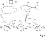
- Fig. 1 shows the system architecture for the proposal.
- Reference number 10 denotes a vehicle.
- the depicted vehicle 10 is exemplified as a car. Shown is a passenger car. In other examples it may be any type of a vehicle. Examples of other types of vehicles are: buses, motorcycles, commercial vehicles, in particular trucks, agricultural machinery, construction machinery, rail vehicles, etc.
- the use of the invention would generally be possible in land vehicles, rail vehicles, watercrafts and aircrafts. This expressively includes robots and drones.
- the vehicle 10 is equipped with an on-board communication module 160 including corresponding antenna such that the vehicle 10 can participate in any form of a mobile communication service.
- Fig. 1 illustrates that vehicle 10 may transmit and receive signals to and from a base station 210 of a mobile communication service provider.
- Such base station 210 may be an eNodeB base station of an LTE (Long Term Evolution) mobile communication service provider or a gNB base station of a 5G mobile communication provider.
- the base station 210 and the corresponding equipment is part of a mobile communication network with a plurality of network cells where each cell is served by one base station 210.
- the base station 210 in Fig. 1 is positioned close to a main road on which the vehicle 10 is driving.
- a mobile terminal corresponds to a user equipment UE, which allows a user to access network services, connecting to the UTRAN or Evolved-UTRAN via the radio interface.
- user equipment corresponds to a smart phone.
- mobile terminals are also used in the vehicles 10.
- the cars 10 are equipped with said on-board communication module OBU 160.
- This OBU corresponds to an LTE, 5G or any other communication module with which the vehicle 10 can receive mobile data in downstream direction and can send such data in upstream or in direct device-to-device direction.
- the Evolved UMTS Terrestrial Radio Acess Network E-UTRAN of LTE consists of a plurality of eNodeBs, providing the E-UTRA user plane (PDCP/RLC/MAC/PHY) and control plane (RRC) protocol terminations towards the UE.
- the eNodeBs are interconnected with each other by means of the so-called X2 interface.
- the eNodeBs are also connected by means of the so-called S1 interface to the EPC (Evolved Packet Core) 200, more specifically to the MME (Mobility Management Entity) by means of the S1-MME and to the Serving Gateway (S-GW) by means of the S1-U interface.
- EPC Evolved Packet Core
- MME Mobility Management Entity
- S-GW Serving Gateway
- Fig. 1 shows that eNodeB 210 is connected to the EPC 200 via the S1 interface and that EPC 200 is connected to the Internet 300.
- the control center computer 320 to which the vehicles 10 send messages to and receive messages from is also connected to the Internet 300.
- the control center computer 320 typically is located in a traffic control center where the operators for the ToD sessions requested by the vehicles 10 are working.
- an infrastructure network component is also shown. This may be exemplified by a road-side unit RSU 310.
- RSU 310 road-side unit
- the various interfaces of the LTE network architecture are standardized. It is particularly referred to the various LTE specifications, which are publicly available for the sake of sufficiently disclosing further implementation details.
- the vehicles 10 may also be equipped with means for surroundings observation.
- the sensor system which is used to capture the environmental objects is based on different measuring methods depending on the application. Widespread technologies are among others RADAR corresponding to Radio Detection and Ranging, LIDAR corresponding to Light detection and ranging, cameras 2D and 3D and ultrasonic sensors.
- Fig. 2 depicts an example of a deadlock situation in which ToD could help to resolve the situation.
- a truck 12 is blocking a one-way road.
- Succeeding vehicles 10 are automated vehicles with level 4 or 5 automated driving capability in the need to pass this obstacle.
- the automated driving functionality needs to respect all the traffic regulations including traffic signs and traffic lights, etc. Since it is not an option for the automated driving function to drive over the sidewalk 14 in order to pass the truck, the vehicle 10 remains behind the truck 12 and waits until the truck 12 moves on. This, however, could take hours if e.g. the truck 12 is stopping inadvertently, e.g. due to a breakdown or a road accident. To overcome this deadlock situation, the vehicles 10 would need to drive over the sidewalk in order to continue their planned route.
- the automated vehicle 10 might not be able to identify that the truck 12 will be there for 1 minute, 1 hour or an indefinitely period of time blocking its path.
- ToD would help to drive the vehicle 10 carefully with two wheels over the sidewalk 14 in order to resolve the blocking situation.
- To initiate a ToD session the vehicle 10 needs to decide if this situation is indeed a deadlock situation with no way out for the automated driving function of the car 10.
- Fig. 3 shows schematically a block diagram of the vehicle's 10 board electronics system.
- Part of the board electronics system is an infotainment system which comprises: the touch-sensitive display unit 20, a computing device 40, an input unit 50, and a memory 60.
- the display unit 20 includes both a display area for displaying variable graphical information and an operator interface (touch-sensitive layer) arranged above the display area) for inputting commands by a user.
- a press button is labelled that allows the driver to manually request a ToD session if the vehicle 10 is blocked and the driver wants the support of ToD to find a way out of the blocking situation.
- There is no need for a dedicated press button 52 if other techniques for manual control are used. This includes selecting an option in a user menu displayed on the display unit 20, detecting the command with speech recognition, or using gesture control means.
- the memory device 60 is connected to the computing device 40 via a further data line 80.
- a pictogram directory and / or symbol directory is deposited with the pictograms and / or symbols for possible overlays of additional information.
- the other parts of the infotainment system such as camera 150, radio 140, navigation device 130, telephone 120 and instrument cluster 110 are connected via the data bus 100 with the computing device 40.
- data bus 100 the high-speed variant of the CAN bus according to ISO standard 11898-2 may be taken into consideration.
- Ethernet-based bus system such as IEEE 802.03cg is another example.
- Bus systems in which the data transmission via optical fibers happens are also usable. Examples are the MOST Bus (Media Oriented System Transport) or the D2B Bus (Domestic Digital Bus).
- MOST Bus Media Oriented System Transport
- D2B Bus Domestic Digital Bus
- the vehicle 10 is equipped with a communication module 160. It can be used for mobile communication, e.g. mobile communication according to the 5G standard.
- Reference numeral 172 denotes an engine control unit.
- the reference numeral 174 corresponds to an ESC control unit corresponding to electronic stability control and the reference numeral 176 denotes a transmission control unit.
- CAN bus system controller area network
- the modern vehicle 10 can also have further components such as further surroundings scanning sensors like a LIDAR (Light Detection and Ranging) sensor 186 or RADAR (Radio Detection and Ranging) sensor 182 and more video cameras 151, e.g. as a front camera, rear camera or side camera. Such sensors are used more and more in vehicles for surroundings observation. Further control devices, such as an automatic driving control unit ADC 184, etc., may be provided in the vehicle.
- the RADAR and LIDAR sensors 182, 186 could be used for scanning a range up to 150 m or 250 m and the cameras 150, 151 cover a range from 30 to 120 m.
- the components 182 to 186 are connected to another communication bus 102.
- the Ethernet-Bus may be a choice for this communication bus 102 due to its higher bandwidth for data transport.
- One Ethernet-Bus adapted to the special needs of car communication is standardized in the IEEE 802.1Q specification.
- a lot of information for surroundings observation may be received via V2V communication from other road participants. Particularly for those road participants not being in line of sight LOS to the observing vehicle it is very advantageous to receive the information about their position and motion via V2V communication.
- Reference number 190 denotes an on-board diagnosis interface.
- the gateway 30 For the purpose of transmitting the vehicle-relevant sensor data via the communication interface 160 to another vehicle 10 or to the control center computer 320, the gateway 30 is provided. This is connected to the different bus systems 100, 102, 104 and 106. The gateway 30 is adapted to convert the data it receives via the one bus the transmission format of the other bus so that it can be distributed in the packets specified there. For the forwarding of this data to the outside, i.e. to another vehicle 10 or to control central computer 320, the on-board communication unit 160 is equipped with the communication interface to receive these data packets and, in turn, to convert them into the transmission format of the correspondingly used mobile radio standard. The gateway 30 takes all the necessary format conversions if data are to be exchanged between the different bus systems if required.
- V2V and V2X communication need to be adapted correspondingly.
- the 3GPP standard setting organisation has been and is releasing features for the new generation of the 5G cellular mobile communication system, including vehicle-to-everything (V2X) features.
- V2X vehicle-to-everything
- a large panel of vehicular use cases have been designed, ranging from infotainment to cooperative driving.
- infotainment to cooperative driving.
- V2N vehicle-to-network
- the automatic driving control unit 184 comprises the algorithms to control the vehicle for automatic driving. Whenever these algorithms detect that the vehicle 10 is stuck in a traffic situation for which the ADC unit 184 does not have the appropriate rights to drive on, the ADC unit 184 should send a ToD session request via gateway 30 and communication module 160 to the control center computer 320 to get help from there.
- the CC there is a computer working place equipped with a number of monitors where a person is responsible for traffic control in a certain region. His job consists basically of the task of governance, surveillance and controlling. It is noted that on some neuralgic places there are surveillance cameras (not shown) installed, the video streams of which will be transferred to the CC, too, where they will be displayed on a monitor. He will take over control of the automatic vehicle 10. By remote control, the vehicle 10 will be controlled to pass the truck 12. Vehicle 10 will be steered to drive partly over the sidewalk to pass the truck 12. After the vehicle 10 has been steered around the truck 12, the tele-operator hands back full control to the automatic driving function in vehicle 10.
- the algorithm running in ADC unit 184 to find out whether or not there is a driving situation existing in which the automatic driving function of the vehicle 10 has no right to carry on with the control of the vehicle 10, is not in focus of the invention.
- This algorithm is working with the data taken or derived from the vehicle's own sensors, such as Radar 182, Lidar 186, cameras 150, 151, etc. Resulting from these environment detection sensors is a very accurate environment map, in which surrounding objects are represented. These surrounding objects may concern other road participants like other vehicles, bicycles, persons walking on the sidewalk; traffic signs and traffic lights; obstacles in the way, width of a road, width of the sidewalk, and so on.
- Fig. 4 shows a flow chart of the program for initiating a ToD session.
- the control center computer 320 each time the vehicle 10 requests a ToD session, either positively acknowledges the entering in the ToD mode or denies it when having evaluated the current situation where the vehicle 10 is stuck in.
- a streaming session will be established between vehicle 10 and control center computer 320.
- the video streams from the cameras 150, 151 and the Radar 182 and Lidar 186 sensors are transferred to the control center computer 320.
- An Internet streaming protocol such as RTSP corresponding to Real Time Streaming Protocol may be used for that purpose.
- Those streams will be decoded and presented to the operator in the control center on his number of monitors. Therefore, either the operator or a machine in the control center decides if the situation is requiring ToD or not and either triggers the sending of an acknowledgement for ToD or denies the entering of the ToD session.
- the message for requesting a ToD session will be transmitted from vehicle 10 to control center computer 320.
- the message will be sent to the control center computer 320 via wireless communication, e.g. cellular mobile communication (LTE, 5G, etc.) or ad hoc communication, e.g. based on WLAN p.
- the control center computer 320 will then start a streaming session between vehicle 10 and the control center computer 320 as mentioned above.
- the sensor data of the environment detection sensors will be streamed from vehicle 10 to the control center computer 320.
- the transmission conditions for the streaming session are however not equal at all locations and depend on various factors. Some of them are traffic density, objects like buildings, other road participants, traffic signs, trees, etc. in the surrounding.
- the senor-based predicted communication technique comprises the steps of observing the surroundings of the transmitting participant, determining the positon and motion of the communication participants, and estimating the transmission conditions for a later point in time.
- step 404 the determination of the QoS prediction for the ToD session.
- the location information corresponds to the location where the vehicle 10 has stopped moving forward and transmitted the request message for a ToD session.
- the time information corresponds to the time when the ToD session shall be started up to the estimated time for the duration of the ToD maneuver.
- the derived QoS prediction includes values for the QoS parameters at least for the uplink direction on the Uu link for LTE or 5G mobile communication or for the WLAN p uplink direction.
- QoS parameters listed in the QoS prediction are data rate DR, end-to-end latency E2EL, error rate in form of packet error rate PER or bit error rate BER, and receiving signal strength RSS.
- step 406 it follows a query in which it is checked if the estimated receiving signal strength RSS is sufficient for the planned ToD session.
- the receiving signal strength RSS There exists a relatively sharp limit for the receiving signal strength RSS up to where it is possible to demodulate the received signals. If the received signals are below that limit the error rate is drastically rising and it is not possible any longer to correct the errors based on the supplied error correction code in the data frame. If the estimated RSS value is below the limit, the ToD session will be aborted right from the beginning. This is depicted in the drawing with a branch arrow that points to the end of the program in step 414.
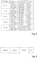
- step 408 the type of data to be exchanged during the ToD session is selected based on the available data rate for the uplink communication. This is done with a table in which the different categories of data are listed for the different data rate ranges. An example of the table is listed in Fig. 5 .
- the data rate DR is presented in units of Mbit/s in the ranges [0.5;1]; [1; 6]; [6; 12]; [12; 30]; and [30; 50] Mbit/s.
- HD video quality images may be streamed with a data rate in the range of 12 to 30 Mbit/s.
- Full HD video quality images may be streamed with a data rate in the range of 30 to 50 Mbit/s.
- 6 Mbit/s it is possible to stream high resolution still pictures with an adequate frame rate of 15 Hz.
- 1 Mbit/s it is only possible to stream SD video quality resolution images at a frame rate of 15 Hz.
- the step 408, therefore, determines what sort of video or image quality (low resolution image, high resolution image, low resolution video, high resolution video) is selected for the ToD session to be invoked. Also the frame rate is roughly determined in this step.
- the type of the ToD session to be invoked is determined.
- direct control the vehicle 10 will be controlled directly under real-time constraints (joystick-like) or better using a remote steering wheel at the control center.
- Indirect control means the vehicle 10 will be controlled in other form without real time constraints, by transmitting waypoints to the vehicle successively which the vehicle 10 needs to reach slowly but with its own control commands and environmental model editions. Very important for this decision is the end-to-end latency.
- the end-to-end latency E2EL is in the range of 0 to 250 ms, the experienced operators are able to control the vehicles directly. This also works with low resolution images with a frame rate of 15 Hz. Above 250 ms latency, with low resolution images no direct control is used for safety reason. With high resolution images at 15 Hz frame rate the direct control is possible in low speed. For SD video quality streaming, at 25 Hz or more, the direct control is selected in the ranges of [6; 12], [12; 30] and [30; 50] Mbit/s data rate when the end-to-end latency E2EL is below 500 ms.
- the direct control is not possible any longer even with video streaming with full HD video quality and more than 25 Hz frame rate since it takes too long until the feedback from the environment detection sensors arrives at the control center.
- the decision for direct control or indirect control it follows a step of adjusting the frame rate to the estimated data rate in step 412. If e.g. the estimated data rate is equal to 5 Mbit/s the still picture streaming can be increased to 20 Hz for HD quality images. Correspondingly, the frame rate could be increased for video streaming.
- the aim is to adjust the frame rate as much as possible to the estimated data rate DR in order to allow a direct control during the ToD session.
- the ToD session will be started by sending the ToD session request message to the control center computer 320.
- interface commands are needed to be transmitted from the control center computer 320 to the vehicle 10. These commands have to be specified to meet the system requirements.
- Essential commands to control the vehicle 10 in the teleoperation mode are desired steering angle, throttle position and brake pressure. For full maneuverability in teleoperation mode commands for shifting gears can be required to be able to reverse together with parking brake commands. This will require access to the CAN-bus 104 on the vehicle 10.
- Status messages from the vehicle 10 to the control center computer 320 are required to monitor the condition and feedback from the driving. In addition to the streaming session, a number of data messages are needed. This can include the actual steering angle, speedometer data and gear indicator. If error codes are set in the vehicle 10, these need to be forwarded to the operator, too, in order to allow for appropriate actions.
- Other status messages are different kinds of status indicators for the vehicle 10. This can be indicators if high beams are being used, fuel level, load weight and so on.
- Fig. 6 shows the message format of the ToD session request message TODREQ.
- the message header is denoted.
- the message header there is at least an entry for message type and another entry for the UE address the message is coming from.
- the on-board communication module 160 has implemented a qualified UE category. Any form of appropriate address information could be used here. Examples are Media Access Control address MAC, International Mobile Station Equipment Identity number IMEI, etc.
- the first field TODSDT of the payload section of the ToD session request message TODREQ there is a listing of the data type to be used during the streaming session of the ToD session. This may be any of the entries in the table of Fig. 5 in column ToD Data Type.
- control type for the ToD session is listed. This can be direct control or indirect control as mentioned above.
- ST field an entry about the start time is transported, i.e. the time or time period when the vehicle 10 wants to start the route.
- ECC an error check code is listed. This may be a CRC code or the like.
- the proposed method and apparatus may be implemented in forms of hardware, software, firmware, special purpose processors, or a combination thereof.
- Special purpose processors may include application specific integrated circuits (ASICs), reduced instruction set computers (RISCs) and/or field programmable gate arrays (FPGAs).
- ASICs application specific integrated circuits
- RISCs reduced instruction set computers
- FPGAs field programmable gate arrays
- the proposed method and apparatus is implemented as a combination of hardware and software.
- the software is preferably implemented as an application program tangibly embodied on a program storage device.
- the application program may be uploaded to and executed by a machine comprising any suitable architecture.
- the machine is implemented on a computer platform having hardware such as one or more central processing units (CPU), a random access memory (RAM), and input/output (I/O) interface(s).
- CPU central processing units
- RAM random access memory
- I/O input/output
- the computer platform also includes an operating system and microinstruction code.
- the various processes and functions described herein may either be part of the microinstruction code or part of the application program (or a combination thereof), which is executed via the operating system.
- various other peripheral devices may be connected to the computer platform such as an additional data storage device and a printing device.
- the elements shown in the figures may be implemented in various forms of hardware, software or combinations thereof. Preferably, these elements are implemented in a combination of hardware and software on one or more appropriately programmed general-purpose devices, which may include a processor, memory and input/output interfaces.
- general-purpose devices which may include a processor, memory and input/output interfaces.
- the phrase "coupled" is defined to mean directly connected to or indirectly connected with through one or more intermediate components. Such intermediate components may include both hardware and software based components.
Abstract
Description
- The disclosure relates to a method for invoking a teleoperated driving session. The proposal also discloses a corresponding apparatus for performing the steps of the method, a corresponding vehicle and a corresponding computer program.
teleoperated driving (ToD) is gathering more and more interest. "Tele-operated Driving" means in this context that an external operator controls the vehicle remotely. The external operator is located in a Control Center (CC). There may be a large distance between the Control Center and the vehicle. Control Center and vehicle are connected via a radio communication system and their backhaul. Primarily the radio communication system is part of a public mobile communication system such as LTE or 5G. - Tele-operated driving belongs to safety-related time-critical applications and the requirements for the exchange of information are low latency, high data rate and high reliability.
- Autonomous driving (sometimes referred to as automatic driving, automated driving or piloted driving) is the movement of vehicles, mobile robots and driverless transport systems which are largely autonomous. There are different degrees of autonomous driving. In Europe various transport ministries, for example in Germany the Federal Institute for Road Systems (Bundesanstalt für Straßenwesen) was involved, worked together and defined the following autonomous stages.
- Level 0: "Driver only", the driver drives himself, steers, gives gas, brakes, etc.
- Level 1: Certain assistance systems help with vehicle operation (including a cruise control system - Automatic Cruise Control ACC).
- Level 2: Partial automation. Therein, automatic parking, tracking function, general longitudinal guidance, acceleration, deceleration, etc. are taken over by the assistance systems (including collision avoidance).
- Level 3: High automation. The driver does not have to monitor the system continuously. The vehicle independently performs functions such as the triggering of the turn signal, lane change and tracking. The driver can turn to other things, but if requested, the system is requested to take over the lead within a pre-warning period. This form of autonomy is technically feasible on motorways. Legislators are working to allow Level 3 vehicles. The legal framework has already been created.
- Level 4: Full automation. The guidance of the vehicle is permanently adopted by the system. If the system is no longer able to handle the tasks, the driver can be asked to take the lead.
- Level 5: No driver required. Apart from setting the target and starting the system, no human intervention is required.
- A slightly different definition of levels is known from the Society of Automotive Engineers SAE. It is referred to the SAE J3016 standard in this regard. This could also be used instead of the above given definition.
- An automated driving vehicle makes its decisions based on the perception of its environment as well as from predefined traffic regulations. It has been observed that an automated vehicle could then experience situations where the vehicle is no longer able to continue its planned route. Incorrect interpretation of the environment, sensor failures, poor road conditions or unidentified events could prevent that the vehicle could continue with its automated driving session. To distinguish all possible iterations to truly identify the root cause of the deadlock situation is not possible.
- Tele-operated driving (ToD) might become a key technology in order to solve issues with L4/L5 driven vehicles, such as interpretation issues or deadlocks. These issues occur when automatic driven vehicles (AV) are not able to interpret and to solve a situation due to not clear traffic conditions, e.g. an accident or a construction site. These vehicles need external instruction from someone else to solve the situation, which will be the so-called control center (CC). A ToD vehicle will be driven remotely by CC.
- It is known that the ToD performance is related to the communication link performance. This link comprises the air interface (Uu link) between the vehicle and the base station and then the connection through the operator backbone (core network). Depending on the quality of the link, the control of the vehicle will be adapted: the vehicle will be controlled directly (joystick-like) or indirectly (waypoints, or environmental model editions). The decision between the two is in the scope of this invention.
- Hence, depending on the communication system's predicted quality of service key performance indicators (KPIs), a question is how is it possible to adapt the ToD sessions accordingly?
- It is therefore one approach to use qualitative descriptions of the QoS and decide which data to transmit and deduct the control type for the ToD session.
- In
US 10 437 247 B2 - In
US 2019/0163176 A1 a method for transferring control of an autonomous vehicle to a remote operator is presented. - In
US 2019/0245647 A1 a method for data communication between communication participants is described including observing the surroundings of the transmitting participant, determining the position and motion of the communication participants, and estimating the transmission conditions at a later point in time. The solution is based on classifying the data for data communication in different categories, the categories determining susceptibility of the data to transmission errors determining which data is transmitted under good transmission conditions only and which data is be transmitted under rough transmission conditions whereby the transmission station plans the transmission of data in different categories. The method further includes selecting for data transmission at a given time for which the transmission conditions have been estimated so the data to be transmitted is in a category fitting to the estimated transmission conditions based on the categories data, and transmitting the selected data. -
WO 2019/081039 A1 describes a closed-loop control of a communication system for tele-operated driving. The proposal relates to a network operator (OMS), a teleoperation application (TOApplication) and an application (TODriver) for a teleoperable vehicle. The OMS is capable of creating a network slice for teleoperating a teleoperable vehicle along at least one route, receiving, from the TOApplication, a slice configuration request comprising the QoS for the at least one route, and configuring the network slice to support the QoS for the at least one route. The TOApplication is capable of communicating, towards the OMS, a request for creating the network slice, receiving, from the teleoperable vehicle, a teleoperation service request comprising a set of teleoperation configurations, mapping each teleoperation configuration to a respective QoS, and sending the slice configuration request comprising the QoS to the OMS. The TODriver is capable of sending the teleoperation service request to the TOApplication, and controlling the route to be followed by the teleoperable vehicle based on information from the TOApplication. - In
US 9 494 935 B2 - Until now, the decision is based on a solution describing the quality of the link, relating it to transmitted data and then making a decision regarding the type of control.
- There are multiple limitations to this solution. First, the description of the QoS is very qualitative. Second, this solution assumes that the control type is dependent on the input (e.g. low resolution images imply indirect control). This assumption is limiting as the transmitted data choice is dependent on the uplink data rate whilst the control type should be chosen using the end to end latency. Indeed, it can be possible to directly command the car with high resolution, high frequency images if the latency is good enough.
- It is not precise in the QoS description and forbids many cases where the car could be directly controlled but different types of data could be transmitted as control is limited by latency and data transmission mostly by data rate.
- It is therefore needed to answer the question: How to select more accurately what type of ToD session control is more appropriate for the determined QoS prediction and what type of data is better suited for the determined QoS prediction in order to improve the performance of the ToD session if needed?
- These and other objects are solved with a method according to
claim 1, a corresponding apparatus for performing steps of the method according to claim 6, a vehicle according to claim 11 and a corresponding computer program according toclaim 12. - The dependent claims contain advantageous developments and improvements to the method, devices and a computer program according to the disclosure.
- To solve the problem, a generic embodiment of the invention consists in a method for invoking a teleoperated driving session, for a vehicle equipped with an automated driving function, hereinafter called ToD session, said vehicle being equipped with a number of environment detection sensors and a communication module for communicating to a control center computer. The method comprises a step of determining a quality of service prediction for the communication between said vehicle and said control center computer for the time when said ToD session should be invoked, and a step of selecting the type of data to be exchanged with said control center computer during said ToD session based on the QoS prediction. The method further comprises a step of selecting the control type for said ToD session based on at least the available end-to-end latency presented in said QoS prediction and a step of starting said ToD session with said selected control type and selected data type to be exchanged with said control center computer.
- There are basically two types of ToD session driving controls existing, direct control where the operator in the control center is using a remote steering wheel and a throttle and braking paddle. Here, he drives the vehicle based on the visual feedback he receives in a streaming session from the environment detection sensors which is established between vehicle and control center computer. The other form of control is an indirect control where the control center computer does not send live control commands with which steering, braking and throttle are directly controlled under real time conditions. Instead, waypoints are submitted to the vehicle lying on a trajectory along which the vehicle shall drive in order to get out of the blocking situation. The autonomous driving function gets the waypoints and drives intermittently to the succeeding locations. This, however, takes much longer than with direct control. Since for the decision which control type is to be used, the end-to-end latency is to be taken into consideration the overall performance of the ToD session is better.
- The performance of the remote control during a ToD session can be further increased, when said step of selecting the type of data to be exchanged with said control center computer during said ToD session comprises a step of selecting the type of data to be exchanged with said control center computer based on the available data rate presented in said QoS prediction.
- Of course, the quality of service prediction is also important for the performance of the ToD session. Primarily the QoS prediction is performed in the vehicle itself based on the observations of the built-in environment detection sensors. It is advantageous if the step of determining a quality of service prediction for the communication between said vehicle and said control center computer for the time when said ToD session should be invoked comprises a step of receiving a QoS prediction from a communication service prediction server or said control center computer. The network operator may have a good QoS prediction for the vehicle position based on historical environment observations and statistical analysis.
- In one preferred embodiment it is advantageous to start the ToD session, with a step of a step of initiating the sending of a ToD session request message to said control center computer (320), wherein said ToD session request message contains the information about the selected control type and the selected data type to be exchanged with said control center computer.
- In a further enhanced embodiment said method according to the invention comprises a further step of evaluating the receiving signal strength RSS of said QoS prediction, and when it is found that the predicted RSS value is below a limit value, the ToD session is terminated. This way the preparation of the ToD session will be stopped when it is found that the receiving signal strength is poor. The idea helps to avoid superfluous ToD session preparations.
- In another embodiment, the invention concerns an apparatus adapted for performing the steps in the method according to the invention. Said apparatus comprises a number of environment detection sensors and a communication module for communicating to a control center computer, and a processing device. It is advantageous, that said processing device comprises means for determining a quality of service prediction for the communication between said vehicle and said control center computer for the time when said teleoperated driving session should be invoked, means for selecting the type of data to be exchanged with said control center computer during said ToD session based on the QoS prediction, means for selecting the control type for said ToD session based on at least the available end-to-end latency presented in said QoS prediction and means for starting the ToD session based on said selected control type and selected data type to be exchanged with said control center computer.
- The starting of the ToD sesseion can be advantageously performed with means for initiating the sending of a ToD session request message to a control center computer. Here, it is further advantageous, that said ToD session request message contains said selected type of data to be exchanged with said control center computer and said selected control type. This way, the most appropriate ToD session will be invoked and the overall performance of the ToD session will be increased.
- In an enhanced embodiment said means for determining a quality of service prediction for the communication between said vehicle and said control center computer for the time when said ToD session should be invoked comprises means for receiving a QoS prediction from a communication service prediction server or said control center computer. This way the accuracy of the QoS predictions may be increased, since at the backend the results of a great plurality of QoS predictions from the past may be archived and can be evaluated with statistical analysis.
- Preferably, said means for receiving a QoS prediction from a communication service prediction server or said control center computer comprise said communication module.
- In a still further embodiment the invention also concerns a vehicle which is equipped with an apparatus according to the invention.
- The proposal also concerns a computer program, comprising program code, which, when run in a processing device of said apparatus according to the invention, cause it to carry out the method according to the invention.
- In summary, with the present invention it is possible to consider the quality of service as multiple values and to consider the impact of all these indicators for the ToD decision (data transmission and type of control).
- The above presented solution is provided for a full ToD session. The same concept could, however, also be applied for sections of the full ToD session. This then means that the future QoS is divided in smaller time intervals, and the transmitted data type and type of control may be changed for each interval. It is, however, noted, that if the receiving signal strength value RSS is too low at some point, the full ToD session will be aborted.
- Exemplary embodiments of the present disclosure are shown in the drawings and are explained in greater detail in the following description.
- In the drawings:
- Fig. 1
- illustrates the principle architecture of a V2V and V2X communication system;
- Fig. 2
- shows a first application scenario of teleoperated Driving;
- Fig. 3
- shows a block diagram of a vehicle's electronics system;
- Fig. 4
- shows a flow chart for a computer program for implementing the proposal;
- Fig. 5
- shows an example of a table with different ranges of a QoS prediction used in an algorithm for selecting the type of data to be exchanged with said control center computer during said ToD session, and for selecting the control type for said ToD session based on at least the available end-to-end latency presented in said QoS prediction; and
- Fig. 6
- shows the format of a ToD session request message.
- The present description illustrates the principles of the present disclosure. It will thus be appreciated that those skilled in the art will be able to devise various arrangements that, although not explicitly described or shown herein, embody the principles of the disclosure.
- All examples and conditional language recited herein are intended for educational purposes to aid the reader in understanding the principles of the disclosure and the concepts contributed by the inventor to furthering the art, and are to be construed as being without limitation to such specifically recited examples and conditions.
- Moreover, all statements herein reciting principles, aspects, and embodiments of the disclosure, as well as specific examples thereof, are intended to encompass both structural and functional equivalents thereof. Additionally, it is intended that such equivalents include both currently known equivalents as well as equivalents developed in the future, i.e. any elements developed that perform the same function, regardless of structure.
- Thus, for example, it will be appreciated by those skilled in the art that the diagrams presented herein represent conceptual views of illustrative circuitry embodying the principles of the disclosure.
- The functions of the various elements shown in the figures may be provided by the use of dedicated hardware as well as hardware capable of executing software in association with appropriate software. When provided by a processor, the functions may be provided by a single dedicated processor, by a single shared processor, or by a plurality of individual processors, some of which may be shared. Moreover, explicit use of the term "processor" or "controller" should not be construed to refer exclusively to hardware capable of executing software, and may implicitly include, without limitation, digital signal processor (DSP) hardware, read only memory (ROM) for storing software, random access memory (RAM), and nonvolatile storage.
- Other hardware, conventional and/or custom, may also be included. Similarly, any switches shown in the figures are conceptual only. Their function may be carried out through the operation of program logic, through dedicated logic, through the interaction of program control and dedicated logic, or even manually, the particular technique being selectable by the implementer as more specifically understood from the context.
- In the claims hereof, any element expressed as a means for performing a specified function is intended to encompass any way of performing that function including, for example, a) a combination of circuit elements that performs that function or b) software in any form, including, therefore, firmware, microcode or the like, combined with appropriate circuitry for executing that software to perform the function. The disclosure as defined by such claims resides in the fact that the functionalities provided by the various recited means are combined and brought together in the manner which the claims call for. It is thus regarded that any means that can provide those functionalities are equivalent to those shown herein.
-
Fig. 1 shows the system architecture for the proposal.Reference number 10 denotes a vehicle. The depictedvehicle 10 is exemplified as a car. Shown is a passenger car. In other examples it may be any type of a vehicle. Examples of other types of vehicles are: buses, motorcycles, commercial vehicles, in particular trucks, agricultural machinery, construction machinery, rail vehicles, etc. The use of the invention would generally be possible in land vehicles, rail vehicles, watercrafts and aircrafts. This expressively includes robots and drones. Thevehicle 10 is equipped with an on-board communication module 160 including corresponding antenna such that thevehicle 10 can participate in any form of a mobile communication service.Fig. 1 illustrates thatvehicle 10 may transmit and receive signals to and from abase station 210 of a mobile communication service provider. -
Such base station 210 may be an eNodeB base station of an LTE (Long Term Evolution) mobile communication service provider or a gNB base station of a 5G mobile communication provider. Thebase station 210 and the corresponding equipment is part of a mobile communication network with a plurality of network cells where each cell is served by onebase station 210. - The
base station 210 inFig. 1 is positioned close to a main road on which thevehicle 10 is driving. Of course, other vehicles may also drive on the road. In the terminology of LTE, a mobile terminal corresponds to a user equipment UE, which allows a user to access network services, connecting to the UTRAN or Evolved-UTRAN via the radio interface. Typically, such user equipment corresponds to a smart phone. Of course, mobile terminals are also used in thevehicles 10. Thecars 10 are equipped with said on-boardcommunication module OBU 160. This OBU corresponds to an LTE, 5G or any other communication module with which thevehicle 10 can receive mobile data in downstream direction and can send such data in upstream or in direct device-to-device direction. - In terms of the LTE mobile communication system, the Evolved UMTS Terrestrial Radio Acess Network E-UTRAN of LTE consists of a plurality of eNodeBs, providing the E-UTRA user plane (PDCP/RLC/MAC/PHY) and control plane (RRC) protocol terminations towards the UE. The eNodeBs are interconnected with each other by means of the so-called X2 interface. The eNodeBs are also connected by means of the so-called S1 interface to the EPC (Evolved Packet Core) 200, more specifically to the MME (Mobility Management Entity) by means of the S1-MME and to the Serving Gateway (S-GW) by means of the S1-U interface.
- From this general architecture
Fig. 1 shows thateNodeB 210 is connected to theEPC 200 via the S1 interface and thatEPC 200 is connected to theInternet 300. Thecontrol center computer 320 to which thevehicles 10 send messages to and receive messages from is also connected to theInternet 300. In the field of cooperative and automated driving thecontrol center computer 320 typically is located in a traffic control center where the operators for the ToD sessions requested by thevehicles 10 are working. Finally, an infrastructure network component is also shown. This may be exemplified by a road-side unit RSU 310. For the ease of implementation, it is considered that all components have assigned an Internet address, typically in the form of an IPv6 address, such that the packets transporting messages between the components can be routed correspondingly. - The various interfaces of the LTE network architecture are standardized. It is particularly referred to the various LTE specifications, which are publicly available for the sake of sufficiently disclosing further implementation details.
- The
vehicles 10 may also be equipped with means for surroundings observation. The sensor system, which is used to capture the environmental objects is based on different measuring methods depending on the application. Widespread technologies are among others RADAR corresponding to Radio Detection and Ranging, LIDAR corresponding to Light detection and ranging, cameras 2D and 3D and ultrasonic sensors. -
Fig. 2 depicts an example of a deadlock situation in which ToD could help to resolve the situation. Atruck 12 is blocking a one-way road. Succeedingvehicles 10 are automated vehicles with level 4 or 5 automated driving capability in the need to pass this obstacle. The automated driving functionality needs to respect all the traffic regulations including traffic signs and traffic lights, etc. Since it is not an option for the automated driving function to drive over thesidewalk 14 in order to pass the truck, thevehicle 10 remains behind thetruck 12 and waits until thetruck 12 moves on. This, however, could take hours if e.g. thetruck 12 is stopping inadvertently, e.g. due to a breakdown or a road accident. To overcome this deadlock situation, thevehicles 10 would need to drive over the sidewalk in order to continue their planned route. - Here, the
automated vehicle 10 might not be able to identify that thetruck 12 will be there for 1 minute, 1 hour or an indefinitely period of time blocking its path. - ToD would help to drive the
vehicle 10 carefully with two wheels over thesidewalk 14 in order to resolve the blocking situation. To initiate a ToD session thevehicle 10 needs to decide if this situation is indeed a deadlock situation with no way out for the automated driving function of thecar 10. - There are basically two possibilities to start a ToD session. Those which are considered to be triggered via a manual request from the inside of the vehicle (Human Interface such as: the press of a button, dictation of a voice command or any other type of human interaction method) and those to be triggered automatically and are based on different conditions which are known by the automated vehicle.
-
Fig. 3 shows schematically a block diagram of the vehicle's 10 board electronics system. Part of the board electronics system is an infotainment system which comprises: the touch-sensitive display unit 20, acomputing device 40, aninput unit 50, and amemory 60. Thedisplay unit 20 includes both a display area for displaying variable graphical information and an operator interface (touch-sensitive layer) arranged above the display area) for inputting commands by a user. With reference number 52 a press button is labelled that allows the driver to manually request a ToD session if thevehicle 10 is blocked and the driver wants the support of ToD to find a way out of the blocking situation. There is no need for adedicated press button 52 if other techniques for manual control are used. This includes selecting an option in a user menu displayed on thedisplay unit 20, detecting the command with speech recognition, or using gesture control means. - The
memory device 60 is connected to thecomputing device 40 via afurther data line 80. In thememory 60, a pictogram directory and / or symbol directory is deposited with the pictograms and / or symbols for possible overlays of additional information. - The other parts of the infotainment system such as
camera 150,radio 140,navigation device 130,telephone 120 andinstrument cluster 110 are connected via thedata bus 100 with thecomputing device 40. Asdata bus 100 the high-speed variant of the CAN bus according to ISO standard 11898-2 may be taken into consideration. Alternatively, for example, the use of an Ethernet-based bus system such as IEEE 802.03cg is another example. Bus systems in which the data transmission via optical fibers happens are also usable. Examples are the MOST Bus (Media Oriented System Transport) or the D2B Bus (Domestic Digital Bus). For inbound and outbound wireless communication, thevehicle 10 is equipped with acommunication module 160. It can be used for mobile communication, e.g. mobile communication according to the 5G standard. -
Reference numeral 172 denotes an engine control unit. Thereference numeral 174 corresponds to an ESC control unit corresponding to electronic stability control and thereference numeral 176 denotes a transmission control unit. The networking of such control units, all of which are allocated to the category of the drive train, typically occurs with the CAN bus system (controller area network) 104. Since various sensors are installed in the motor vehicle and these are no longer only connected to individual control units, such sensor data are also distributed via thebus system 104 to the individual control devices. - However, the
modern vehicle 10 can also have further components such as further surroundings scanning sensors like a LIDAR (Light Detection and Ranging)sensor 186 or RADAR (Radio Detection and Ranging)sensor 182 andmore video cameras 151, e.g. as a front camera, rear camera or side camera. Such sensors are used more and more in vehicles for surroundings observation. Further control devices, such as an automatic drivingcontrol unit ADC 184, etc., may be provided in the vehicle. The RADAR andLIDAR sensors cameras components 182 to 186 are connected to anothercommunication bus 102. The Ethernet-Bus may be a choice for thiscommunication bus 102 due to its higher bandwidth for data transport. One Ethernet-Bus adapted to the special needs of car communication is standardized in the IEEE 802.1Q specification. Moreover, a lot of information for surroundings observation may be received via V2V communication from other road participants. Particularly for those road participants not being in line of sight LOS to the observing vehicle it is very advantageous to receive the information about their position and motion via V2V communication. -
Reference number 190 denotes an on-board diagnosis interface. - For the purpose of transmitting the vehicle-relevant sensor data via the
communication interface 160 to anothervehicle 10 or to thecontrol center computer 320, thegateway 30 is provided. This is connected to thedifferent bus systems gateway 30 is adapted to convert the data it receives via the one bus the transmission format of the other bus so that it can be distributed in the packets specified there. For the forwarding of this data to the outside, i.e. to anothervehicle 10 or to controlcentral computer 320, the on-board communication unit 160 is equipped with the communication interface to receive these data packets and, in turn, to convert them into the transmission format of the correspondingly used mobile radio standard. Thegateway 30 takes all the necessary format conversions if data are to be exchanged between the different bus systems if required. - Since automated driving is on the rise, a lot more data needs to be exchanged among the road participants and also between the road participants and the network. The communication systems for V2V and V2X communication need to be adapted correspondingly. The 3GPP standard setting organisation has been and is releasing features for the new generation of the 5G cellular mobile communication system, including vehicle-to-everything (V2X) features. A large panel of vehicular use cases have been designed, ranging from infotainment to cooperative driving. Depending on the application, the requirement on the Uu link in the scope of vehicle-to-network (V2N) communication drastically changes. When it comes to safety-related time-critical applications such as ToD, in which a command centre (CC) takes over some driving functions of the
vehicle 10, these requirements are the exchange of information with low latency, high data rate and high reliability. - The automatic
driving control unit 184 comprises the algorithms to control the vehicle for automatic driving. Whenever these algorithms detect that thevehicle 10 is stuck in a traffic situation for which theADC unit 184 does not have the appropriate rights to drive on, theADC unit 184 should send a ToD session request viagateway 30 andcommunication module 160 to thecontrol center computer 320 to get help from there. - At the CC there is a computer working place equipped with a number of monitors where a person is responsible for traffic control in a certain region. His job consists basically of the task of governance, surveillance and controlling. It is noted that on some neuralgic places there are surveillance cameras (not shown) installed, the video streams of which will be transferred to the CC, too, where they will be displayed on a monitor. He will take over control of the
automatic vehicle 10. By remote control, thevehicle 10 will be controlled to pass thetruck 12.Vehicle 10 will be steered to drive partly over the sidewalk to pass thetruck 12. After thevehicle 10 has been steered around thetruck 12, the tele-operator hands back full control to the automatic driving function invehicle 10. - The algorithm running in
ADC unit 184 to find out whether or not there is a driving situation existing in which the automatic driving function of thevehicle 10 has no right to carry on with the control of thevehicle 10, is not in focus of the invention. This algorithm is working with the data taken or derived from the vehicle's own sensors, such asRadar 182,Lidar 186,cameras vehicle 10 is stuck in a deadlock situation, it will start a program for initiating a ToD session with thecontrol center computer 320. -
Fig. 4 shows a flow chart of the program for initiating a ToD session. Thecontrol center computer 320, each time thevehicle 10 requests a ToD session, either positively acknowledges the entering in the ToD mode or denies it when having evaluated the current situation where thevehicle 10 is stuck in. To evaluate the situation in the control center a streaming session will be established betweenvehicle 10 andcontrol center computer 320. In this streaming session, the video streams from thecameras Radar 182 andLidar 186 sensors are transferred to thecontrol center computer 320. An Internet streaming protocol such as RTSP corresponding to Real Time Streaming Protocol may be used for that purpose. Those streams will be decoded and presented to the operator in the control center on his number of monitors. Therefore, either the operator or a machine in the control center decides if the situation is requiring ToD or not and either triggers the sending of an acknowledgement for ToD or denies the entering of the ToD session. - Before starting the streaming session, the message for requesting a ToD session will be transmitted from
vehicle 10 to controlcenter computer 320. The message will be sent to thecontrol center computer 320 via wireless communication, e.g. cellular mobile communication (LTE, 5G, etc.) or ad hoc communication, e.g. based on WLAN p. Thecontrol center computer 320 will then start a streaming session betweenvehicle 10 and thecontrol center computer 320 as mentioned above. The sensor data of the environment detection sensors will be streamed fromvehicle 10 to thecontrol center computer 320. The transmission conditions for the streaming session are however not equal at all locations and depend on various factors. Some of them are traffic density, objects like buildings, other road participants, traffic signs, trees, etc. in the surrounding. Also, it is dependent on geographical conditions and weather conditions. It may also depend on the time, such as time of day, day of week, month of year, etc. Since the transmission conditions are dynamically changing all the time, there is a need to estimate the transmission conditions before starting the ToD session. Obviously, it is not possible to start video streaming with full HD resolution for the case where the transmission conditions are not good enough. One solution for this issue is a so-called sensor-based predicted communication technique. Normal link adaptation takes time, and these techniques applied to current transmission conditions are not always very efficient in highly varying V2X channels. The conditions may be obsolete before link adaptation has been performed. The senor-based predicted communication technique comprises the steps of observing the surroundings of the transmitting participant, determining the positon and motion of the communication participants, and estimating the transmission conditions for a later point in time. This solution is disclosed in the patent application publication documentEP 3 535 374 A1 andDE 10 2015 214 968 A1EP 18198192.9 - After the start of the program in
step 402, it follows instep 404 the determination of the QoS prediction for the ToD session. In this step, therefore, the results from the sensor-based QoS prediction as disclosed in above mentioned reference are collected. The location information corresponds to the location where thevehicle 10 has stopped moving forward and transmitted the request message for a ToD session. The time information corresponds to the time when the ToD session shall be started up to the estimated time for the duration of the ToD maneuver. - The derived QoS prediction includes values for the QoS parameters at least for the uplink direction on the Uu link for LTE or 5G mobile communication or for the WLAN p uplink direction. Examples of QoS parameters listed in the QoS prediction are data rate DR, end-to-end latency E2EL, error rate in form of packet error rate PER or bit error rate BER, and receiving signal strength RSS.
- In
step 406 it follows a query in which it is checked if the estimated receiving signal strength RSS is sufficient for the planned ToD session. There exists a relatively sharp limit for the receiving signal strength RSS up to where it is possible to demodulate the received signals. If the received signals are below that limit the error rate is drastically rising and it is not possible any longer to correct the errors based on the supplied error correction code in the data frame. If the estimated RSS value is below the limit, the ToD session will be aborted right from the beginning. This is depicted in the drawing with a branch arrow that points to the end of the program instep 414. - If the estimated RSS value is good enough, the program proceeds further with
step 408. Instep 408 the type of data to be exchanged during the ToD session is selected based on the available data rate for the uplink communication. This is done with a table in which the different categories of data are listed for the different data rate ranges. An example of the table is listed inFig. 5 . The data rate DR is presented in units of Mbit/s in the ranges [0.5;1]; [1; 6]; [6; 12]; [12; 30]; and [30; 50] Mbit/s. For the example of video images captured byvideo camera step 408, therefore, determines what sort of video or image quality (low resolution image, high resolution image, low resolution video, high resolution video) is selected for the ToD session to be invoked. Also the frame rate is roughly determined in this step. Instep 410, the type of the ToD session to be invoked is determined. There are two types existing, direct control and indirect control. Here, with direct control thevehicle 10 will be controlled directly under real-time constraints (joystick-like) or better using a remote steering wheel at the control center. Indirect control means thevehicle 10 will be controlled in other form without real time constraints, by transmitting waypoints to the vehicle successively which thevehicle 10 needs to reach slowly but with its own control commands and environmental model editions. Very important for this decision is the end-to-end latency. If the end-to-end latency E2EL is in the range of 0 to 250 ms, the experienced operators are able to control the vehicles directly. This also works with low resolution images with a frame rate of 15 Hz. Above 250 ms latency, with low resolution images no direct control is used for safety reason. With high resolution images at 15 Hz frame rate the direct control is possible in low speed. For SD video quality streaming, at 25 Hz or more, the direct control is selected in the ranges of [6; 12], [12; 30] and [30; 50] Mbit/s data rate when the end-to-end latency E2EL is below 500 ms. If the latency is higher than 500 ms, the direct control is not possible any longer even with video streaming with full HD video quality and more than 25 Hz frame rate since it takes too long until the feedback from the environment detection sensors arrives at the control center. Once the decision for direct control or indirect control has been made, it follows a step of adjusting the frame rate to the estimated data rate instep 412. If e.g. the estimated data rate is equal to 5 Mbit/s the still picture streaming can be increased to 20 Hz for HD quality images. Correspondingly, the frame rate could be increased for video streaming. The aim is to adjust the frame rate as much as possible to the estimated data rate DR in order to allow a direct control during the ToD session. Instep 414, the ToD session will be started by sending the ToD session request message to thecontrol center computer 320. - To control the
vehicle 10, interface commands are needed to be transmitted from thecontrol center computer 320 to thevehicle 10. These commands have to be specified to meet the system requirements. Essential commands to control thevehicle 10 in the teleoperation mode are desired steering angle, throttle position and brake pressure. For full maneuverability in teleoperation mode commands for shifting gears can be required to be able to reverse together with parking brake commands. This will require access to the CAN-bus 104 on thevehicle 10. Status messages from thevehicle 10 to thecontrol center computer 320 are required to monitor the condition and feedback from the driving. In addition to the streaming session, a number of data messages are needed. This can include the actual steering angle, speedometer data and gear indicator. If error codes are set in thevehicle 10, these need to be forwarded to the operator, too, in order to allow for appropriate actions. Other status messages are different kinds of status indicators for thevehicle 10. This can be indicators if high beams are being used, fuel level, load weight and so on. -
Fig. 6 shows the message format of the ToD session request message TODREQ. With reference sign TODREQH the message header is denoted. In the message header there is at least an entry for message type and another entry for the UE address the message is coming from. As explained before, the on-board communication module 160 has implemented a qualified UE category. Any form of appropriate address information could be used here. Examples are Media Access Control address MAC, International Mobile Station Equipment Identity number IMEI, etc. In the first field TODSDT of the payload section of the ToD session request message TODREQ there is a listing of the data type to be used during the streaming session of the ToD session. This may be any of the entries in the table ofFig. 5 in column ToD Data Type. In the field TODSCT the control type for the ToD session is listed. This can be direct control or indirect control as mentioned above. In the following ST field an entry about the start time is transported, i.e. the time or time period when thevehicle 10 wants to start the route. In the last field, ECC an error check code is listed. This may be a CRC code or the like. - It is to be understood that the proposed method and apparatus may be implemented in forms of hardware, software, firmware, special purpose processors, or a combination thereof. Special purpose processors may include application specific integrated circuits (ASICs), reduced instruction set computers (RISCs) and/or field programmable gate arrays (FPGAs). Preferably, the proposed method and apparatus is implemented as a combination of hardware and software. Moreover, the software is preferably implemented as an application program tangibly embodied on a program storage device. The application program may be uploaded to and executed by a machine comprising any suitable architecture. Preferably, the machine is implemented on a computer platform having hardware such as one or more central processing units (CPU), a random access memory (RAM), and input/output (I/O) interface(s). The computer platform also includes an operating system and microinstruction code. The various processes and functions described herein may either be part of the microinstruction code or part of the application program (or a combination thereof), which is executed via the operating system. In addition, various other peripheral devices may be connected to the computer platform such as an additional data storage device and a printing device.
- It should be understood that the elements shown in the figures may be implemented in various forms of hardware, software or combinations thereof. Preferably, these elements are implemented in a combination of hardware and software on one or more appropriately programmed general-purpose devices, which may include a processor, memory and input/output interfaces. Herein, the phrase "coupled" is defined to mean directly connected to or indirectly connected with through one or more intermediate components. Such intermediate components may include both hardware and software based components.
- It is to be further understood that, because some of the constituent system components and method steps depicted in the accompanying figures are preferably implemented in software, the actual connections between the system components (or the process steps) may differ depending upon the manner in which the proposed method and apparatus is programmed. Given the teachings herein, one of ordinary skill in the related art will be able to contemplate these and similar implementations or configurations of the proposed method and apparatus.
-
- 10
- Vehicle
- 12
- Truck
- 14
- Sidewalk
- 20
- Touch Screen
- 30
- Gateway
- 40
- Computing Device
- 50
- Operation Element Unit
- 52
- Press Button
- 60
- Memory Unit
- 70
- Data Line to Display Unit
- 80
- Data Line to Memory Unit
- 90
- Data Line to Operation Element Unit
- 100
- 1st Data Bus
- 102
- 2nd Data Bus
- 104
- 3rd Data Bus
- 106
- 4th Data Bus
- 110
- Multifunction Display
- 120
- Telephone
- 130
- Navigation System
- 140
- Radio
- 150
- Front Camera
- 151
- Back, Left, Right Camera
- 160
- On-Board Unit
- 172
- Engine Control Device
- 174
- ESP Control Device
- 176
- Transmission Control Device
- 182
- RADAR Sensor
- 184
- Automatic Driving Control Device
- 186
- LIDAR Sensor
- 190
- On-Board Diagnosis Interface
- 200
- Evolved Packet Core
- 210
- Base Station
- 220
- Communication Service Prediction Server
- 300
- Internet
- 310
- Road Side Unit
- 320
- Control Center Computer
- 400
- Algorithm
- 402 - 416
- different Program Steps of a Computer Program
- PC5
- V2V Communication Link
- S1
- S1-Interface
- Uu
- V2N Communication Link
Claims (12)
- Method for invoking a teleoperated Driving session for a vehicle (10) equipped with an automated driving function, hereinafter called ToD session, said vehicle (10) being equipped with a number of environment detection sensors (150, 151, 182, 186) and a communication module (160) for communicating to a control center computer (320), comprising a step of determining a quality of service prediction for the communication between said vehicle (10) and said control center computer (320) for the time when said ToD session should be invoked, and a step of selecting the type of data to be exchanged with said control center computer (320) during said ToD session based on the QoS prediction, characterized by a step of selecting the control type for said ToD session based on at least the available end-to-end latency presented in said QoS prediction and a step of starting said ToD session with said selected control type and selected data type to be exchanged with said control center computer (320).
- Method according to claim 1, wherein said step of selecting the type of data to be exchanged with said control center computer (320) during said ToD session comprises a step of selecting the type of data to be exchanged with said control center computer (320) based on the available data rate presented in said QoS prediction.
- Method according to claim 1 or 2, wherein said step of determining a quality of service prediction for the communication between said vehicle (10) and said control center computer (320) for the time when said ToD session should be invoked comprises a step of receiving a QoS prediction from a communication service prediction server (220).
- Method according to claim any one of the previous claims, wherein said step of starting said ToD session comprises a step of initiating the sending of a ToD session request message to said control center computer (320), wherein said ToD session request message contains said selected type of data to be exchanged with said control center computer (320) and said selected control type.
- Method according to any one of the previous claims, wherein said method comprises a further step of evaluating the receiving signal strength RSS of said QoS prediction, and when it is found that the predicted RSS value is below a limit value, the ToD session is terminated.
- Apparatus adapted for performing the steps in the method according to any one of the previous claims, wherein said apparatus comprises a number of environment detection sensors (150, 151, 182, 186) and a communication module (160) for communicating to a control center computer (320), and a processing device (184), wherein said processing device (184) comprises means for determining a quality of service prediction for the communication between said vehicle (10) and said control center computer (320) for the time when said teleoperated driving session should be invoked, means for selecting the type of data to be exchanged with said control center computer (320) during said ToD session based on the QoS prediction, and means for selecting the control type for said ToD session based on at least the available end-to-end latency presented in said QoS prediction and means for starting said ToD session with said selected type of data to be exchanged with said control center computer (320) and said selected control type.
- Apparatus according to claim 6, characterized in that said means for determining a quality of service prediction for the communication between said vehicle (10) and said control center computer (320) for the time when said ToD session should be invoked comprises means for receiving a QoS prediction from a communication service prediction server (220) or said control center computer (320).
- Apparatus according to claim 6 or 7, characterized in that said means for receiving a QoS prediction from a communication service prediction server (220) or said control center computer (320) comprise said communication module (160).
- Apparatus according to any one of claims 6 to 8, characterized in that said means for starting said ToD session request comprises means for initiating the sending of a ToD session request message to a control center computer (320), wherein said ToD session request message contains said selected type of data to be exchanged with said control center computer (320) and said selected control type.
- Apparatus according to any one of the claims 6 to 9, wherein said processing device (184) comprises means for evaluating the receiving signal strength RSS of said QoS prediction, and for terminating the ToD session when it is found that the predicted RSS value is below a limit value.
- Vehicle (10), characterized in that said vehicle (10) is equipped with an apparatus according to any one of claims 6 to 10.
- Computer program, comprising program code, which when run in a processing device (184) of said apparatus according to any one of claims 6 to 10, performs the steps of the method according to any one of the claims 1 to 5.
Priority Applications (4)
| Application Number | Priority Date | Filing Date | Title |
|---|---|---|---|
| EP20158259.0A EP3869843A1 (en) | 2020-02-19 | 2020-02-19 | Method for invoking a teleoperated driving session, apparatus for performing the steps of the method, vehicle and computer program |
| KR1020210022081A KR102478809B1 (en) | 2020-02-19 | 2021-02-18 | Method for invoking a teleoperated driving session, apparatus for performing the steps of the method, vehicle and computer program |
| US17/178,339 US11513513B2 (en) | 2020-02-19 | 2021-02-18 | Method for invoking a teleoperated driving session, apparatus for performing the steps of the method, vehicle and computer program |
| CN202110189113.0A CN113276873A (en) | 2020-02-19 | 2021-02-19 | Method for invoking a remotely operated driving session, device for performing the steps of the method, vehicle and computer program |
Applications Claiming Priority (1)
| Application Number | Priority Date | Filing Date | Title |
|---|---|---|---|
| EP20158259.0A EP3869843A1 (en) | 2020-02-19 | 2020-02-19 | Method for invoking a teleoperated driving session, apparatus for performing the steps of the method, vehicle and computer program |
Publications (1)
| Publication Number | Publication Date |
|---|---|
| EP3869843A1 true EP3869843A1 (en) | 2021-08-25 |
Family
ID=69723800
Family Applications (1)
| Application Number | Title | Priority Date | Filing Date |
|---|---|---|---|
| EP20158259.0A Pending EP3869843A1 (en) | 2020-02-19 | 2020-02-19 | Method for invoking a teleoperated driving session, apparatus for performing the steps of the method, vehicle and computer program |
Country Status (4)
| Country | Link |
|---|---|
| US (1) | US11513513B2 (en) |
| EP (1) | EP3869843A1 (en) |
| KR (1) | KR102478809B1 (en) |
| CN (1) | CN113276873A (en) |
Families Citing this family (3)
| Publication number | Priority date | Publication date | Assignee | Title |
|---|---|---|---|---|
| CN113911139B (en) * | 2021-11-12 | 2023-02-28 | 湖北芯擎科技有限公司 | Vehicle control method and device and electronic equipment |
| CN114475654B (en) * | 2022-01-13 | 2024-03-15 | 香港中文大学(深圳) | Vehicle control method and device and computer readable storage medium |
| WO2024024114A1 (en) * | 2022-07-29 | 2024-02-01 | 日本電信電話株式会社 | Object detection rate calculation device, object detection rate calculation method, and program |
Citations (8)
| Publication number | Priority date | Publication date | Assignee | Title |
|---|---|---|---|---|
| US9494935B2 (en) | 2014-11-13 | 2016-11-15 | Toyota Motor Engineering & Manufacturing North America, Inc. | Remote operation of autonomous vehicle in unexpected environment |
| DE102015214968A1 (en) | 2015-08-05 | 2017-02-09 | Volkswagen Aktiengesellschaft | Method and device for adapting at least one parameter of a communication system |
| WO2019081039A1 (en) | 2017-10-27 | 2019-05-02 | Huawei Technologies Co., Ltd. | A closed-loop control of a communication system for teleoperated driving. |
| US20190163176A1 (en) | 2017-11-30 | 2019-05-30 | drive.ai Inc. | Method for transferring control of an autonomous vehicle to a remote operator |
| US20190245647A1 (en) | 2018-02-07 | 2019-08-08 | Volkswagen Aktiengesellschaft | Method for data communication between at least two participants of a wireless communication system, corresponding control unit and transportation vehicle equipped with a control unit and a computer program |
| EP3535374A1 (en) | 2016-11-01 | 2019-09-11 | The Procter and Gamble Company | Leuco polymers as bluing agents in laundry care compositions |
| WO2019180700A1 (en) * | 2018-03-18 | 2019-09-26 | Liveu Ltd. | Device, system, and method of autonomous driving and tele-operated vehicles |
| US10437247B2 (en) | 2017-08-10 | 2019-10-08 | Udelv Inc. | Multi-stage operation of autonomous vehicles |
Family Cites Families (15)
| Publication number | Priority date | Publication date | Assignee | Title |
|---|---|---|---|---|
| US7844396B2 (en) | 2005-09-13 | 2010-11-30 | Deere & Company | Method and system for modular data processing for a vehicle control system |
| US8259566B2 (en) | 2005-09-20 | 2012-09-04 | Qualcomm Incorporated | Adaptive quality of service policy for dynamic networks |
| US10271261B1 (en) * | 2014-04-07 | 2019-04-23 | Sqwaq, Inc. | Prioritized transmission of different data types over bonded communication channels |
| JP6421481B2 (en) * | 2014-07-18 | 2018-11-14 | 株式会社デンソー | Remote control device and remote control system using the same |
| RU2761270C2 (en) * | 2015-05-13 | 2021-12-06 | Убер Текнолоджис, Инк. | System and method for providing transportation |
| US9690290B2 (en) * | 2015-06-04 | 2017-06-27 | Toyota Motor Engineering & Manufacturing North America, Inc. | Situation-based transfer of vehicle sensor data during remote operation of autonomous vehicles |
| KR20170048766A (en) * | 2015-10-27 | 2017-05-10 | 현대자동차주식회사 | Apparatus and method for controlling vehicle data communciation under all-ip network |
| CN114643995A (en) | 2015-11-04 | 2022-06-21 | 祖克斯有限公司 | Simulation system and method for autonomous vehicle |
| US9507346B1 (en) | 2015-11-04 | 2016-11-29 | Zoox, Inc. | Teleoperation system and method for trajectory modification of autonomous vehicles |
| US20190279447A1 (en) * | 2015-12-03 | 2019-09-12 | Autoconnect Holdings Llc | Automatic vehicle diagnostic detection and communication |
| US10322717B2 (en) | 2016-01-04 | 2019-06-18 | GM Global Technology Operations LLC | Expert mode for vehicles |
| US10699305B2 (en) * | 2016-11-21 | 2020-06-30 | Nio Usa, Inc. | Smart refill assistant for electric vehicles |
| US10109198B2 (en) * | 2017-03-08 | 2018-10-23 | GM Global Technology Operations LLC | Method and apparatus of networked scene rendering and augmentation in vehicular environments in autonomous driving systems |
| US20190286151A1 (en) * | 2018-03-14 | 2019-09-19 | GM Global Technology Operations LLC | Automated driving systems and control logic for cloud-based scenario planning of autonomous vehicles |
| US20200133308A1 (en) * | 2018-10-18 | 2020-04-30 | Cartica Ai Ltd | Vehicle to vehicle (v2v) communication less truck platooning |
-
2020
- 2020-02-19 EP EP20158259.0A patent/EP3869843A1/en active Pending
-
2021
- 2021-02-18 US US17/178,339 patent/US11513513B2/en active Active
- 2021-02-18 KR KR1020210022081A patent/KR102478809B1/en active IP Right Grant
- 2021-02-19 CN CN202110189113.0A patent/CN113276873A/en active Pending
Patent Citations (8)
| Publication number | Priority date | Publication date | Assignee | Title |
|---|---|---|---|---|
| US9494935B2 (en) | 2014-11-13 | 2016-11-15 | Toyota Motor Engineering & Manufacturing North America, Inc. | Remote operation of autonomous vehicle in unexpected environment |
| DE102015214968A1 (en) | 2015-08-05 | 2017-02-09 | Volkswagen Aktiengesellschaft | Method and device for adapting at least one parameter of a communication system |
| EP3535374A1 (en) | 2016-11-01 | 2019-09-11 | The Procter and Gamble Company | Leuco polymers as bluing agents in laundry care compositions |
| US10437247B2 (en) | 2017-08-10 | 2019-10-08 | Udelv Inc. | Multi-stage operation of autonomous vehicles |
| WO2019081039A1 (en) | 2017-10-27 | 2019-05-02 | Huawei Technologies Co., Ltd. | A closed-loop control of a communication system for teleoperated driving. |
| US20190163176A1 (en) | 2017-11-30 | 2019-05-30 | drive.ai Inc. | Method for transferring control of an autonomous vehicle to a remote operator |
| US20190245647A1 (en) | 2018-02-07 | 2019-08-08 | Volkswagen Aktiengesellschaft | Method for data communication between at least two participants of a wireless communication system, corresponding control unit and transportation vehicle equipped with a control unit and a computer program |
| WO2019180700A1 (en) * | 2018-03-18 | 2019-09-26 | Liveu Ltd. | Device, system, and method of autonomous driving and tele-operated vehicles |
Also Published As
| Publication number | Publication date |
|---|---|
| KR20210106377A (en) | 2021-08-30 |
| KR102478809B1 (en) | 2022-12-19 |
| US11513513B2 (en) | 2022-11-29 |
| CN113276873A (en) | 2021-08-20 |
| US20210255617A1 (en) | 2021-08-19 |
Similar Documents
| Publication | Publication Date | Title |
|---|---|---|
| US11513513B2 (en) | Method for invoking a teleoperated driving session, apparatus for performing the steps of the method, vehicle and computer program | |
| CN110876147B (en) | Method and device for predicting service quality of communication, vehicle and background server | |
| CN110996302B (en) | Method and apparatus for predicting quality of service of communication link of communication device | |
| CN109501801B (en) | Method, control unit, vehicle and computer program for planning a collision avoidance maneuver | |
| CN109017757B (en) | Automobile remote designated driving method and system | |
| EP3859709A1 (en) | Method for planning a cooperative driving maneuver, corresponding control unit and vehicle equipped with a control unit as well as computer program | |
| CN111988164B (en) | Method for predicting the quality of service of a communication between at least two communication partners and device for carrying out the steps of the method | |
| US10916128B2 (en) | Method for data communication between at least two participants of a wireless communication system, corresponding control unit and transportation vehicle equipped with a control unit, and computer program | |
| US20210271239A1 (en) | Automatic vehicle and method for operating the same | |
| US20220159075A1 (en) | Method, computer program and apparatus for invoking a tele-operated driving session | |
| EP3893073B1 (en) | Method and apparatus for invoking a tele-operated driving session | |
| EP3845991B1 (en) | Method for invoking a tele-operated driving session, apparatus for performing the steps of the method, vehicle and computer program | |
| EP4050450B1 (en) | Methods, computer programs and apparatus for performing a tele-operated driving session |
Legal Events
| Date | Code | Title | Description |
|---|---|---|---|
| PUAI | Public reference made under article 153(3) epc to a published international application that has entered the european phase |
Free format text: ORIGINAL CODE: 0009012 |
|
| STAA | Information on the status of an ep patent application or granted ep patent |
Free format text: STATUS: THE APPLICATION HAS BEEN PUBLISHED |
|
| AK | Designated contracting states |
Kind code of ref document: A1 Designated state(s): AL AT BE BG CH CY CZ DE DK EE ES FI FR GB GR HR HU IE IS IT LI LT LU LV MC MK MT NL NO PL PT RO RS SE SI SK SM TR |
|
| STAA | Information on the status of an ep patent application or granted ep patent |
Free format text: STATUS: REQUEST FOR EXAMINATION WAS MADE |
|
| 17P | Request for examination filed |
Effective date: 20220225 |
|
| RBV | Designated contracting states (corrected) |
Designated state(s): AL AT BE BG CH CY CZ DE DK EE ES FI FR GB GR HR HU IE IS IT LI LT LU LV MC MK MT NL NO PL PT RO RS SE SI SK SM TR |
|
| GRAP | Despatch of communication of intention to grant a patent |
Free format text: ORIGINAL CODE: EPIDOSNIGR1 |
|
| STAA | Information on the status of an ep patent application or granted ep patent |
Free format text: STATUS: GRANT OF PATENT IS INTENDED |
|
| INTG | Intention to grant announced |
Effective date: 20230210 |
|
| GRAJ | Information related to disapproval of communication of intention to grant by the applicant or resumption of examination proceedings by the epo deleted |
Free format text: ORIGINAL CODE: EPIDOSDIGR1 |
|
| STAA | Information on the status of an ep patent application or granted ep patent |
Free format text: STATUS: REQUEST FOR EXAMINATION WAS MADE |
|
| STAA | Information on the status of an ep patent application or granted ep patent |
Free format text: STATUS: EXAMINATION IS IN PROGRESS |
|
| INTC | Intention to grant announced (deleted) | ||
| 17Q | First examination report despatched |
Effective date: 20230616 |
|
| GRAP | Despatch of communication of intention to grant a patent |
Free format text: ORIGINAL CODE: EPIDOSNIGR1 |
|
| STAA | Information on the status of an ep patent application or granted ep patent |
Free format text: STATUS: GRANT OF PATENT IS INTENDED |