EP3869622A1 - Prise de recharge pour un véhicule électrique - Google Patents
Prise de recharge pour un véhicule électrique Download PDFInfo
- Publication number
- EP3869622A1 EP3869622A1 EP21000029.5A EP21000029A EP3869622A1 EP 3869622 A1 EP3869622 A1 EP 3869622A1 EP 21000029 A EP21000029 A EP 21000029A EP 3869622 A1 EP3869622 A1 EP 3869622A1
- Authority
- EP
- European Patent Office
- Prior art keywords
- charging socket
- charging
- contact
- signal lines
- power
- Prior art date
- Legal status (The legal status is an assumption and is not a legal conclusion. Google has not performed a legal analysis and makes no representation as to the accuracy of the status listed.)
- Granted
Links
- 238000000034 method Methods 0.000 claims abstract description 12
- 238000005538 encapsulation Methods 0.000 claims abstract description 5
- 239000011521 glass Substances 0.000 claims description 14
- 239000004020 conductor Substances 0.000 claims description 8
- XLYOFNOQVPJJNP-UHFFFAOYSA-N water Substances O XLYOFNOQVPJJNP-UHFFFAOYSA-N 0.000 claims description 7
- 238000007765 extrusion coating Methods 0.000 claims description 4
- 230000005540 biological transmission Effects 0.000 claims description 2
- 238000009413 insulation Methods 0.000 description 8
- 238000002788 crimping Methods 0.000 description 2
- 238000002955 isolation Methods 0.000 description 2
- 238000009833 condensation Methods 0.000 description 1
- 230000005494 condensation Effects 0.000 description 1
- 239000000428 dust Substances 0.000 description 1
- 238000005516 engineering process Methods 0.000 description 1
- 230000007613 environmental effect Effects 0.000 description 1
- 230000013011 mating Effects 0.000 description 1
- 230000001105 regulatory effect Effects 0.000 description 1
- 238000007789 sealing Methods 0.000 description 1
Images


Classifications
-
- H—ELECTRICITY
- H01—ELECTRIC ELEMENTS
- H01R—ELECTRICALLY-CONDUCTIVE CONNECTIONS; STRUCTURAL ASSOCIATIONS OF A PLURALITY OF MUTUALLY-INSULATED ELECTRICAL CONNECTING ELEMENTS; COUPLING DEVICES; CURRENT COLLECTORS
- H01R4/00—Electrically-conductive connections between two or more conductive members in direct contact, i.e. touching one another; Means for effecting or maintaining such contact; Electrically-conductive connections having two or more spaced connecting locations for conductors and using contact members penetrating insulation
- H01R4/70—Insulation of connections
-
- B—PERFORMING OPERATIONS; TRANSPORTING
- B60—VEHICLES IN GENERAL
- B60L—PROPULSION OF ELECTRICALLY-PROPELLED VEHICLES; SUPPLYING ELECTRIC POWER FOR AUXILIARY EQUIPMENT OF ELECTRICALLY-PROPELLED VEHICLES; ELECTRODYNAMIC BRAKE SYSTEMS FOR VEHICLES IN GENERAL; MAGNETIC SUSPENSION OR LEVITATION FOR VEHICLES; MONITORING OPERATING VARIABLES OF ELECTRICALLY-PROPELLED VEHICLES; ELECTRIC SAFETY DEVICES FOR ELECTRICALLY-PROPELLED VEHICLES
- B60L53/00—Methods of charging batteries, specially adapted for electric vehicles; Charging stations or on-board charging equipment therefor; Exchange of energy storage elements in electric vehicles
- B60L53/10—Methods of charging batteries, specially adapted for electric vehicles; Charging stations or on-board charging equipment therefor; Exchange of energy storage elements in electric vehicles characterised by the energy transfer between the charging station and the vehicle
- B60L53/14—Conductive energy transfer
- B60L53/16—Connectors, e.g. plugs or sockets, specially adapted for charging electric vehicles
-
- B—PERFORMING OPERATIONS; TRANSPORTING
- B60—VEHICLES IN GENERAL
- B60L—PROPULSION OF ELECTRICALLY-PROPELLED VEHICLES; SUPPLYING ELECTRIC POWER FOR AUXILIARY EQUIPMENT OF ELECTRICALLY-PROPELLED VEHICLES; ELECTRODYNAMIC BRAKE SYSTEMS FOR VEHICLES IN GENERAL; MAGNETIC SUSPENSION OR LEVITATION FOR VEHICLES; MONITORING OPERATING VARIABLES OF ELECTRICALLY-PROPELLED VEHICLES; ELECTRIC SAFETY DEVICES FOR ELECTRICALLY-PROPELLED VEHICLES
- B60L53/00—Methods of charging batteries, specially adapted for electric vehicles; Charging stations or on-board charging equipment therefor; Exchange of energy storage elements in electric vehicles
- B60L53/10—Methods of charging batteries, specially adapted for electric vehicles; Charging stations or on-board charging equipment therefor; Exchange of energy storage elements in electric vehicles characterised by the energy transfer between the charging station and the vehicle
- B60L53/14—Conductive energy transfer
- B60L53/18—Cables specially adapted for charging electric vehicles
-
- H—ELECTRICITY
- H01—ELECTRIC ELEMENTS
- H01R—ELECTRICALLY-CONDUCTIVE CONNECTIONS; STRUCTURAL ASSOCIATIONS OF A PLURALITY OF MUTUALLY-INSULATED ELECTRICAL CONNECTING ELEMENTS; COUPLING DEVICES; CURRENT COLLECTORS
- H01R13/00—Details of coupling devices of the kinds covered by groups H01R12/70 or H01R24/00 - H01R33/00
- H01R13/46—Bases; Cases
- H01R13/502—Bases; Cases composed of different pieces
-
- H—ELECTRICITY
- H01—ELECTRIC ELEMENTS
- H01R—ELECTRICALLY-CONDUCTIVE CONNECTIONS; STRUCTURAL ASSOCIATIONS OF A PLURALITY OF MUTUALLY-INSULATED ELECTRICAL CONNECTING ELEMENTS; COUPLING DEVICES; CURRENT COLLECTORS
- H01R13/00—Details of coupling devices of the kinds covered by groups H01R12/70 or H01R24/00 - H01R33/00
- H01R13/46—Bases; Cases
- H01R13/52—Dustproof, splashproof, drip-proof, waterproof, or flameproof cases
- H01R13/5205—Sealing means between cable and housing, e.g. grommet
- H01R13/5208—Sealing means between cable and housing, e.g. grommet having at least two cable receiving openings
-
- H—ELECTRICITY
- H01—ELECTRIC ELEMENTS
- H01R—ELECTRICALLY-CONDUCTIVE CONNECTIONS; STRUCTURAL ASSOCIATIONS OF A PLURALITY OF MUTUALLY-INSULATED ELECTRICAL CONNECTING ELEMENTS; COUPLING DEVICES; CURRENT COLLECTORS
- H01R13/00—Details of coupling devices of the kinds covered by groups H01R12/70 or H01R24/00 - H01R33/00
- H01R13/46—Bases; Cases
- H01R13/52—Dustproof, splashproof, drip-proof, waterproof, or flameproof cases
- H01R13/5227—Dustproof, splashproof, drip-proof, waterproof, or flameproof cases with evacuation of penetrating liquids
-
- H—ELECTRICITY
- H01—ELECTRIC ELEMENTS
- H01R—ELECTRICALLY-CONDUCTIVE CONNECTIONS; STRUCTURAL ASSOCIATIONS OF A PLURALITY OF MUTUALLY-INSULATED ELECTRICAL CONNECTING ELEMENTS; COUPLING DEVICES; CURRENT COLLECTORS
- H01R13/00—Details of coupling devices of the kinds covered by groups H01R12/70 or H01R24/00 - H01R33/00
- H01R13/648—Protective earth or shield arrangements on coupling devices, e.g. anti-static shielding
- H01R13/658—High frequency shielding arrangements, e.g. against EMI [Electro-Magnetic Interference] or EMP [Electro-Magnetic Pulse]
- H01R13/6581—Shield structure
- H01R13/6585—Shielding material individually surrounding or interposed between mutually spaced contacts
- H01R13/6589—Shielding material individually surrounding or interposed between mutually spaced contacts with wires separated by conductive housing parts
-
- H—ELECTRICITY
- H01—ELECTRIC ELEMENTS
- H01R—ELECTRICALLY-CONDUCTIVE CONNECTIONS; STRUCTURAL ASSOCIATIONS OF A PLURALITY OF MUTUALLY-INSULATED ELECTRICAL CONNECTING ELEMENTS; COUPLING DEVICES; CURRENT COLLECTORS
- H01R13/00—Details of coupling devices of the kinds covered by groups H01R12/70 or H01R24/00 - H01R33/00
- H01R13/66—Structural association with built-in electrical component
- H01R13/665—Structural association with built-in electrical component with built-in electronic circuit
- H01R13/6683—Structural association with built-in electrical component with built-in electronic circuit with built-in sensor
-
- H—ELECTRICITY
- H01—ELECTRIC ELEMENTS
- H01R—ELECTRICALLY-CONDUCTIVE CONNECTIONS; STRUCTURAL ASSOCIATIONS OF A PLURALITY OF MUTUALLY-INSULATED ELECTRICAL CONNECTING ELEMENTS; COUPLING DEVICES; CURRENT COLLECTORS
- H01R2201/00—Connectors or connections adapted for particular applications
- H01R2201/26—Connectors or connections adapted for particular applications for vehicles
-
- Y—GENERAL TAGGING OF NEW TECHNOLOGICAL DEVELOPMENTS; GENERAL TAGGING OF CROSS-SECTIONAL TECHNOLOGIES SPANNING OVER SEVERAL SECTIONS OF THE IPC; TECHNICAL SUBJECTS COVERED BY FORMER USPC CROSS-REFERENCE ART COLLECTIONS [XRACs] AND DIGESTS
- Y02—TECHNOLOGIES OR APPLICATIONS FOR MITIGATION OR ADAPTATION AGAINST CLIMATE CHANGE
- Y02T—CLIMATE CHANGE MITIGATION TECHNOLOGIES RELATED TO TRANSPORTATION
- Y02T10/00—Road transport of goods or passengers
- Y02T10/60—Other road transportation technologies with climate change mitigation effect
- Y02T10/70—Energy storage systems for electromobility, e.g. batteries
-
- Y—GENERAL TAGGING OF NEW TECHNOLOGICAL DEVELOPMENTS; GENERAL TAGGING OF CROSS-SECTIONAL TECHNOLOGIES SPANNING OVER SEVERAL SECTIONS OF THE IPC; TECHNICAL SUBJECTS COVERED BY FORMER USPC CROSS-REFERENCE ART COLLECTIONS [XRACs] AND DIGESTS
- Y02—TECHNOLOGIES OR APPLICATIONS FOR MITIGATION OR ADAPTATION AGAINST CLIMATE CHANGE
- Y02T—CLIMATE CHANGE MITIGATION TECHNOLOGIES RELATED TO TRANSPORTATION
- Y02T10/00—Road transport of goods or passengers
- Y02T10/60—Other road transportation technologies with climate change mitigation effect
- Y02T10/7072—Electromobility specific charging systems or methods for batteries, ultracapacitors, supercapacitors or double-layer capacitors
-
- Y—GENERAL TAGGING OF NEW TECHNOLOGICAL DEVELOPMENTS; GENERAL TAGGING OF CROSS-SECTIONAL TECHNOLOGIES SPANNING OVER SEVERAL SECTIONS OF THE IPC; TECHNICAL SUBJECTS COVERED BY FORMER USPC CROSS-REFERENCE ART COLLECTIONS [XRACs] AND DIGESTS
- Y02—TECHNOLOGIES OR APPLICATIONS FOR MITIGATION OR ADAPTATION AGAINST CLIMATE CHANGE
- Y02T—CLIMATE CHANGE MITIGATION TECHNOLOGIES RELATED TO TRANSPORTATION
- Y02T90/00—Enabling technologies or technologies with a potential or indirect contribution to GHG emissions mitigation
- Y02T90/10—Technologies relating to charging of electric vehicles
- Y02T90/14—Plug-in electric vehicles
Definitions
- the invention is based on a charging socket for an electric vehicle according to the preamble of independent claim 1.
- Such charging sockets are used in electric vehicles. Charging connectors for charging the batteries in the electric vehicle are plugged into the charging sockets.
- the WO 2017/162651 A1 shows a charging socket for an electric vehicle.
- the charging socket is equipped with two power lines through which the necessary charging energy can be transmitted.
- the object of the invention is to provide a reliable charging socket for an electric vehicle.
- the charging socket according to the invention is intended for an electric vehicle, in particular for a car.
- the charging socket has at least two electrical power lines.
- the power lines each consist of a central metallic line through which high charging currents can be transmitted.
- the metallic line usually has a large cross section.
- the charging socket also has at least two signal lines for transmitting control signals during the charging process. This allows the charging process to be adapted to different charging situations. In particular, a distinction is made here between a fast charging process with a correspondingly high energy supply per unit of time and a charging process in a normal house network.
- the charging socket has a housing and a contact carrier connected to it.
- the housing usually protrudes into the interior of an electric vehicle and thus protects the components of the charging socket.
- the contact carrier forms the plug-in area for a charging connector that is visible on the outside of the electric vehicle.
- a seal is preferably arranged between the housing and the contact carrier. This improves the media tightness of the charging socket.
- the signal lines are arranged in two cable managers that are spaced apart from one another and aligned parallel to one another.
- the cable managers each have through openings into which the signal lines are introduced.
- the signal lines are encapsulated between the cable managers. In particular, this ensures particularly precise and torsion-proof positioning of the signal lines in the charging socket. This also increases the tensile strength of the signal lines.
- a sealing ring is preferably arranged on the extrusion coating. This achieves a particularly high level of media tightness for the charging socket in the area of the signal line entry.
- an opening with an integrally formed outlet connection for water drainage is provided in the plug-in area of the contact carrier.
- the charging socket has power contact elements which are each connected to a power line.
- the charging socket advantageously has at least one temperature sensor which is arranged in the vicinity of a power contact element. The data from the temperature sensor can be used to control the charging process.
- Signal contact elements are connected to the signal lines of the charging socket.
- the power contact elements and the signal contact elements are fixed in the contact carrier by means of latching means. This enables simple assembly of the charging socket.
- a circumferential first insulation which is formed from a non-conductive plastic (plastic jacket), is applied to the central metallic line.
- a metallic braided shield is arranged on the first insulation. The braided shield is used for electromagnetic shielding of the respective power line.
- a circumferential second insulation is provided on the braided shield.
- the charging socket has metallic contact glasses which are electrically conductively connected to the (two) braided shields of the at least two power lines.
- the contact glasses have two circular connection areas in which the power lines run. The connection areas are connected by a tapered web.
- the charging socket has a screw-on dome which is connected to the contact glasses in an electrically conductive manner. This connection takes place on the bridge described above.
- An electrical shielding conductor can be connected to the screw-on dome and can be connected in an electrically conductive manner for the shielding connection to the body of the electric vehicle.
- a metallic sleeve is preferably fastened in an electrically conductive manner on the respective braided shield of the electrical power lines.
- the crimping technique is usually used for this. This connection technology is easy to implement and at the same time reliable.
- the sleeve preferably has a circumferential groove, a metallic ring spring being arranged in the circumferential groove.
- the electrical connection between the contact glasses and the respective braided shield of the electrical power lines is implemented via the metallic sleeve and the annular spring arranged therein. This electrical contact has proven to be particularly reliable because it allows tolerances and mechanical movements of the contact elements to be compensated for during the plugging process.
- the screw-on dome of the charging socket has a ring cable lug for connecting the shield conductor.
- the shield conductor can be easily and reliably connected in an electrically conductive manner via this.
- the charging socket advantageously has a housing which includes the contact glasses.
- the housing is usually made of plastic.
- the contact glasses are arranged inside the housing. When installed, the housing protects the charging socket against mechanical damage and against the ingress of media such as water and dust.
- the housing is preferably designed in two parts. This makes it easier to assemble the charging socket.
- the ring cable lug of the screw-on dome protrudes from the housing. This allows the shield conductor to be connected even after the charging socket has been assembled.
- the Figure 1 shows two electrical power lines 2 that are connected to the charging socket 1.
- the respective power line 2 consists of a central metallic line 3, which is designed for the transmission of high currents.
- a circumferential first insulation 5 is arranged above this.
- a metallic braided shield 4 is located on the first insulation 5.
- a second insulation 6 is arranged around the braided shield 4.
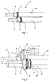
- the power lines 2 are stripped or prepared, as shown in Figure 1 is shown.
- the bare metallic lines 3 can be seen in the front part.
- Part of the first insulation 5 can be seen further back.
- the braided shield 4 then appears, which is covered by the second insulation 6 even further to the rear.
- a sleeve 8. is attached to the respective braided shield using the crimping technique.
- a further sleeve 27 is crimped for reasons of stability.
- the sleeve 8 has a circumferential groove in which an annular spring 9 is arranged.
- the respective circular recess of the contact glasses 7 engages the respective annular spring 9, as in FIG Figure 2 can be seen.
- the braided shields 4 of the power lines 2 are electrically conductive via the contact glasses 7 contacted.
- the braided shields 4 are then also electrically conductively contacted with one another via the contact glasses 7.
- the contact glasses 7 have two circular openings which encompass the respective power lines 2.
- the circular openings are connected to one another via a triangular web 10.
- the web 10 has an opening in which a screw-on dome 11 is arranged.
- the screw-on dome 11 has a ring cable lug 12, via which an electrical shield conductor (not shown) can be connected.
- the shield conductor can be connected to the body of the electric vehicle and thus connected in an electrically conductive manner.
- the signal lines 16 of the charging socket 1 are shown, which are arranged in two cable managers 17 spaced apart from one another and aligned parallel to one another.
- the cable managers 17 each have a plurality of feed-through openings through which a signal line 16 runs.
- the signal lines 16 are provided with an extrusion coating 18 between the cable managers 17. As a result, the signal lines 16 can be handled very easily when the charging socket 1 is assembled.
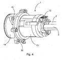
- the housing 13 of the charging socket 1 is made in two parts.
- the two housing parts are connected via a locking mechanism that is shown in Figure 4 is easy to see.
- the contact carrier 14 of the charging socket 1 protrudes from the electric vehicle.
- the contact carrier 14 protrudes into the two-part housing 13 of the charging socket 1.
- the contact carrier 14 is screwed to the housing 13.
- the contact carrier 14 has openings 15 via which the charging socket 1 can be fastened to an electric vehicle, for example screwed or riveted.
- FIG 7 an open representation of the charging socket 1 can be seen.
- the signal lines 16 bundled via the cable manager 17 and the encapsulation 18 are provided with a seal 19 in the area of the encapsulation 18.
- the power lines 2 also each have a seal 20.
- Signal contact elements 22 are connected to each of the signal lines 16. For illustrative reasons, however, the signal lines 16 do not run all the way to the signal contact elements 22.
- Power contact elements 21 are connected to the power lines 2.
- the contact elements 21, 22 are fixed in the contact carrier 14 via latching means 23, 23 ′.
- a temperature sensor 26 is arranged in the vicinity of a power contact element 21. This can be used to collect data about the charging process, which can then be regulated accordingly via a control unit in the charging station.
- FIG 8 the charging socket 1 according to the invention is shown on the plug side in perspective.
- a recess 24 with an opening is provided on the inner wall.
- a water drain 24 is formed on the outside, which has a substantially cylindrical shape with a funnel-like outlet. This is used to remove the water that gets into the charging socket 1, for example when it rains when charging outside.
Landscapes
- Engineering & Computer Science (AREA)
- Power Engineering (AREA)
- Transportation (AREA)
- Mechanical Engineering (AREA)
- Details Of Connecting Devices For Male And Female Coupling (AREA)
- Connector Housings Or Holding Contact Members (AREA)
- Charge And Discharge Circuits For Batteries Or The Like (AREA)
- Electric Propulsion And Braking For Vehicles (AREA)
Applications Claiming Priority (1)
| Application Number | Priority Date | Filing Date | Title |
|---|---|---|---|
| DE102020104511.5A DE102020104511A1 (de) | 2020-02-20 | 2020-02-20 | Ladebuchse für ein Elektrofahrzeug |
Publications (2)
| Publication Number | Publication Date |
|---|---|
| EP3869622A1 true EP3869622A1 (fr) | 2021-08-25 |
| EP3869622B1 EP3869622B1 (fr) | 2023-12-13 |
Family
ID=74494708
Family Applications (1)
| Application Number | Title | Priority Date | Filing Date |
|---|---|---|---|
| EP21000029.5A Active EP3869622B1 (fr) | 2020-02-20 | 2021-01-29 | Prise de recharge pour un véhicule électrique |
Country Status (3)
| Country | Link |
|---|---|
| EP (1) | EP3869622B1 (fr) |
| DE (1) | DE102020104511A1 (fr) |
| PL (1) | PL3869622T3 (fr) |
Cited By (4)
| Publication number | Priority date | Publication date | Assignee | Title |
|---|---|---|---|---|
| US11584245B2 (en) * | 2019-09-25 | 2023-02-21 | Audi Ag | Charging socket for a power supply arrangement, corresponding power supply arrangement, and method for operating a charging socket |
| WO2023030445A1 (fr) * | 2021-09-02 | 2023-03-09 | 长春捷翼汽车零部件有限公司 | Système de transmission d'énergie électrique pour véhicule, et appareil de charge et véhicule électrique |
| WO2023174292A1 (fr) * | 2022-03-14 | 2023-09-21 | 吉林省中赢高科技有限公司 | Ensemble connecteur à refroidissement à semi-conducteurs, et véhicule |
| EP4372930A1 (fr) * | 2022-11-18 | 2024-05-22 | Aptiv Technologies Limited | Connecteur avec une plaque de mise à la terre commune |
Families Citing this family (1)
| Publication number | Priority date | Publication date | Assignee | Title |
|---|---|---|---|---|
| DE102022100403A1 (de) | 2022-01-10 | 2023-07-13 | HARTING Automotive GmbH | Verfahren zur Herstellung eines Inlets, Inlet und Multikontaktstecker |
Citations (3)
| Publication number | Priority date | Publication date | Assignee | Title |
|---|---|---|---|---|
| KR100774654B1 (ko) * | 2006-07-10 | 2007-11-08 | 현대자동차주식회사 | 쉴드형 커넥터 |
| US20160006156A1 (en) * | 2013-03-19 | 2016-01-07 | Sumitomo Wiring Systems, Ltd. | Vehicle-side connector |
| WO2017162651A1 (fr) | 2016-03-23 | 2017-09-28 | Phoenix Contact E-Mobility Gmbh | Système de contacts de puissance pour une fiche de charge et/ou une prise de charge, fiche de charge et station de charge pour la livraison d'énergie électrique à un récepteur d'énergie électrique |
Family Cites Families (3)
| Publication number | Priority date | Publication date | Assignee | Title |
|---|---|---|---|---|
| DE60133787T2 (de) | 2000-03-07 | 2009-06-25 | AutoNetworks Technologies, Ltd., Nagoya | Abgeschirmter Verbinder und Anschlusskontaktanordnung für elektrisches abgeschirmtes Kabel |
| CN102870280B (zh) | 2010-04-09 | 2015-12-02 | 富加宜汽车控股公司 | 电磁屏蔽装置 |
| DE102016121847B4 (de) | 2016-11-15 | 2019-06-06 | Phoenix Contact E-Mobility Gmbh | Steckverbinderteil und Verfahren zum Montieren eines Steckverbinderteils |
-
2020
- 2020-02-20 DE DE102020104511.5A patent/DE102020104511A1/de active Pending
-
2021
- 2021-01-29 EP EP21000029.5A patent/EP3869622B1/fr active Active
- 2021-01-29 PL PL21000029.5T patent/PL3869622T3/pl unknown
Patent Citations (3)
| Publication number | Priority date | Publication date | Assignee | Title |
|---|---|---|---|---|
| KR100774654B1 (ko) * | 2006-07-10 | 2007-11-08 | 현대자동차주식회사 | 쉴드형 커넥터 |
| US20160006156A1 (en) * | 2013-03-19 | 2016-01-07 | Sumitomo Wiring Systems, Ltd. | Vehicle-side connector |
| WO2017162651A1 (fr) | 2016-03-23 | 2017-09-28 | Phoenix Contact E-Mobility Gmbh | Système de contacts de puissance pour une fiche de charge et/ou une prise de charge, fiche de charge et station de charge pour la livraison d'énergie électrique à un récepteur d'énergie électrique |
Cited By (4)
| Publication number | Priority date | Publication date | Assignee | Title |
|---|---|---|---|---|
| US11584245B2 (en) * | 2019-09-25 | 2023-02-21 | Audi Ag | Charging socket for a power supply arrangement, corresponding power supply arrangement, and method for operating a charging socket |
| WO2023030445A1 (fr) * | 2021-09-02 | 2023-03-09 | 长春捷翼汽车零部件有限公司 | Système de transmission d'énergie électrique pour véhicule, et appareil de charge et véhicule électrique |
| WO2023174292A1 (fr) * | 2022-03-14 | 2023-09-21 | 吉林省中赢高科技有限公司 | Ensemble connecteur à refroidissement à semi-conducteurs, et véhicule |
| EP4372930A1 (fr) * | 2022-11-18 | 2024-05-22 | Aptiv Technologies Limited | Connecteur avec une plaque de mise à la terre commune |
Also Published As
| Publication number | Publication date |
|---|---|
| PL3869622T3 (pl) | 2024-05-06 |
| EP3869622B1 (fr) | 2023-12-13 |
| DE102020104511A1 (de) | 2021-08-26 |
Similar Documents
| Publication | Publication Date | Title |
|---|---|---|
| EP3869622B1 (fr) | Prise de recharge pour un véhicule électrique | |
| EP3869632A1 (fr) | Prise de recharge pour un véhicule électrique | |
| DE102008052327A1 (de) | Elektromagnetisch abgeschirmter Steckverbinder | |
| DE102008006340A1 (de) | Steckverbindungsanordnung mit aufgeformtem abgeschirmtem Gehäuse | |
| DE202017101060U1 (de) | Steckverbinder, insbesondere für eine Hochstromanwendung | |
| DE102018121400A1 (de) | Elektrischer Steckverbinder, Hochvoltleitungssatz, Hochvoltsystem und Verfahren zum Anbringen eines elektrischen Steckverbinders | |
| DE102012009877A1 (de) | Steckverbindergehäuse und Steckverbinder | |
| EP2551978B1 (fr) | Dispositif d'acheminement d'une ligne électrique au travers d'un boîtier | |
| EP3767750A1 (fr) | Connecteur enfichable électrique, élément de protection isolant et procédé de montage d'un connecteur enfichable électrique | |
| DE102008054585B4 (de) | Winkelsteckverbindung für geschirmte Kabel | |
| EP2337161B1 (fr) | Agencement de prise et dispositif d'étanchéification pour au moins une ligne, notamment une ligne électrique | |
| EP3496211B1 (fr) | Ligne électrique | |
| DE102014103436A1 (de) | Elektrischer Verbinder, elektrischer Anschluss, sowie elektrische Einrichtung oder Aggregat | |
| DE102018201160A1 (de) | Hochspannungsdurchführung, elektrisches Gerät mit Hochspannungsdurchführung und Verfahren zur Herstellung des elektrischen Gerätes | |
| WO2021239421A1 (fr) | Élément de manchon de blindage | |
| DE102019121872A1 (de) | Hybridsteckverbinder | |
| DE102016200138A1 (de) | Wasserdichte Struktur und Kabelbaum | |
| WO2020025087A1 (fr) | Système de connecteur enfichable modulaire | |
| BE1027151A1 (de) | Steckverbinder mit einem als Gussteil ausgebildeten Kontaktierungselement | |
| DE102011055581A1 (de) | Kontakteinsatz für eine Anhängersteckdose | |
| DE102023106339A1 (de) | Erdungsmodul für ein Steckverbindermodularsystem sowie Steckverbindermodularsystem und modularer Steckverbinder mit demselben | |
| DE102023132377A1 (de) | Kopplungsvorrichtung | |
| DE102014202296A1 (de) | Elektrisches Gerät und Verbindungsanordnung mit einem elektrischen Gerät | |
| DE9217862U1 (de) | Kabelendstecker für Koaxialkabel | |
| DE102023133830A1 (de) | Kontaktstecker, DC Kontakthalter und DC Trennstelle eines DC Steckers eines Ladekabels |
Legal Events
| Date | Code | Title | Description |
|---|---|---|---|
| PUAI | Public reference made under article 153(3) epc to a published international application that has entered the european phase |
Free format text: ORIGINAL CODE: 0009012 |
|
| STAA | Information on the status of an ep patent application or granted ep patent |
Free format text: STATUS: THE APPLICATION HAS BEEN PUBLISHED |
|
| AK | Designated contracting states |
Kind code of ref document: A1 Designated state(s): AL AT BE BG CH CY CZ DE DK EE ES FI FR GB GR HR HU IE IS IT LI LT LU LV MC MK MT NL NO PL PT RO RS SE SI SK SM TR |
|
| STAA | Information on the status of an ep patent application or granted ep patent |
Free format text: STATUS: REQUEST FOR EXAMINATION WAS MADE |
|
| 17P | Request for examination filed |
Effective date: 20220127 |
|
| RBV | Designated contracting states (corrected) |
Designated state(s): AL AT BE BG CH CY CZ DE DK EE ES FI FR GB GR HR HU IE IS IT LI LT LU LV MC MK MT NL NO PL PT RO RS SE SI SK SM TR |
|
| P01 | Opt-out of the competence of the unified patent court (upc) registered |
Effective date: 20230603 |
|
| GRAP | Despatch of communication of intention to grant a patent |
Free format text: ORIGINAL CODE: EPIDOSNIGR1 |
|
| STAA | Information on the status of an ep patent application or granted ep patent |
Free format text: STATUS: GRANT OF PATENT IS INTENDED |
|
| INTG | Intention to grant announced |
Effective date: 20230907 |
|
| GRAS | Grant fee paid |
Free format text: ORIGINAL CODE: EPIDOSNIGR3 |
|
| GRAA | (expected) grant |
Free format text: ORIGINAL CODE: 0009210 |
|
| STAA | Information on the status of an ep patent application or granted ep patent |
Free format text: STATUS: THE PATENT HAS BEEN GRANTED |
|
| AK | Designated contracting states |
Kind code of ref document: B1 Designated state(s): AL AT BE BG CH CY CZ DE DK EE ES FI FR GB GR HR HU IE IS IT LI LT LU LV MC MK MT NL NO PL PT RO RS SE SI SK SM TR |
|
| REG | Reference to a national code |
Ref country code: GB Ref legal event code: FG4D Free format text: NOT ENGLISH |
|
| REG | Reference to a national code |
Ref country code: CH Ref legal event code: EP |
|
| REG | Reference to a national code |
Ref country code: DE Ref legal event code: R096 Ref document number: 502021002138 Country of ref document: DE |
|
| REG | Reference to a national code |
Ref country code: IE Ref legal event code: FG4D Free format text: LANGUAGE OF EP DOCUMENT: GERMAN |
|
| PG25 | Lapsed in a contracting state [announced via postgrant information from national office to epo] |
Ref country code: GR Free format text: LAPSE BECAUSE OF FAILURE TO SUBMIT A TRANSLATION OF THE DESCRIPTION OR TO PAY THE FEE WITHIN THE PRESCRIBED TIME-LIMIT Effective date: 20240314 |
|
| REG | Reference to a national code |
Ref country code: LT Ref legal event code: MG9D |
|
| PG25 | Lapsed in a contracting state [announced via postgrant information from national office to epo] |
Ref country code: LT Free format text: LAPSE BECAUSE OF FAILURE TO SUBMIT A TRANSLATION OF THE DESCRIPTION OR TO PAY THE FEE WITHIN THE PRESCRIBED TIME-LIMIT Effective date: 20231213 |
|
| REG | Reference to a national code |
Ref country code: NL Ref legal event code: MP Effective date: 20231213 |
|
| PG25 | Lapsed in a contracting state [announced via postgrant information from national office to epo] |
Ref country code: ES Free format text: LAPSE BECAUSE OF FAILURE TO SUBMIT A TRANSLATION OF THE DESCRIPTION OR TO PAY THE FEE WITHIN THE PRESCRIBED TIME-LIMIT Effective date: 20231213 |
|
| PG25 | Lapsed in a contracting state [announced via postgrant information from national office to epo] |
Ref country code: LT Free format text: LAPSE BECAUSE OF FAILURE TO SUBMIT A TRANSLATION OF THE DESCRIPTION OR TO PAY THE FEE WITHIN THE PRESCRIBED TIME-LIMIT Effective date: 20231213 Ref country code: GR Free format text: LAPSE BECAUSE OF FAILURE TO SUBMIT A TRANSLATION OF THE DESCRIPTION OR TO PAY THE FEE WITHIN THE PRESCRIBED TIME-LIMIT Effective date: 20240314 Ref country code: ES Free format text: LAPSE BECAUSE OF FAILURE TO SUBMIT A TRANSLATION OF THE DESCRIPTION OR TO PAY THE FEE WITHIN THE PRESCRIBED TIME-LIMIT Effective date: 20231213 Ref country code: BG Free format text: LAPSE BECAUSE OF FAILURE TO SUBMIT A TRANSLATION OF THE DESCRIPTION OR TO PAY THE FEE WITHIN THE PRESCRIBED TIME-LIMIT Effective date: 20240313 |
|
| PGFP | Annual fee paid to national office [announced via postgrant information from national office to epo] |
Ref country code: DE Payment date: 20240129 Year of fee payment: 4 |
|
| PG25 | Lapsed in a contracting state [announced via postgrant information from national office to epo] |
Ref country code: NL Free format text: LAPSE BECAUSE OF FAILURE TO SUBMIT A TRANSLATION OF THE DESCRIPTION OR TO PAY THE FEE WITHIN THE PRESCRIBED TIME-LIMIT Effective date: 20231213 |
|
| PG25 | Lapsed in a contracting state [announced via postgrant information from national office to epo] |
Ref country code: SE Free format text: LAPSE BECAUSE OF FAILURE TO SUBMIT A TRANSLATION OF THE DESCRIPTION OR TO PAY THE FEE WITHIN THE PRESCRIBED TIME-LIMIT Effective date: 20231213 Ref country code: RS Free format text: LAPSE BECAUSE OF FAILURE TO SUBMIT A TRANSLATION OF THE DESCRIPTION OR TO PAY THE FEE WITHIN THE PRESCRIBED TIME-LIMIT Effective date: 20231213 Ref country code: NO Free format text: LAPSE BECAUSE OF FAILURE TO SUBMIT A TRANSLATION OF THE DESCRIPTION OR TO PAY THE FEE WITHIN THE PRESCRIBED TIME-LIMIT Effective date: 20240313 Ref country code: NL Free format text: LAPSE BECAUSE OF FAILURE TO SUBMIT A TRANSLATION OF THE DESCRIPTION OR TO PAY THE FEE WITHIN THE PRESCRIBED TIME-LIMIT Effective date: 20231213 Ref country code: LV Free format text: LAPSE BECAUSE OF FAILURE TO SUBMIT A TRANSLATION OF THE DESCRIPTION OR TO PAY THE FEE WITHIN THE PRESCRIBED TIME-LIMIT Effective date: 20231213 Ref country code: HR Free format text: LAPSE BECAUSE OF FAILURE TO SUBMIT A TRANSLATION OF THE DESCRIPTION OR TO PAY THE FEE WITHIN THE PRESCRIBED TIME-LIMIT Effective date: 20231213 |
|
| PGFP | Annual fee paid to national office [announced via postgrant information from national office to epo] |
Ref country code: IT Payment date: 20240131 Year of fee payment: 4 Ref country code: FR Payment date: 20240125 Year of fee payment: 4 |
|
| PG25 | Lapsed in a contracting state [announced via postgrant information from national office to epo] |
Ref country code: IS Free format text: LAPSE BECAUSE OF FAILURE TO SUBMIT A TRANSLATION OF THE DESCRIPTION OR TO PAY THE FEE WITHIN THE PRESCRIBED TIME-LIMIT Effective date: 20240413 |
|
| PG25 | Lapsed in a contracting state [announced via postgrant information from national office to epo] |
Ref country code: CZ Free format text: LAPSE BECAUSE OF FAILURE TO SUBMIT A TRANSLATION OF THE DESCRIPTION OR TO PAY THE FEE WITHIN THE PRESCRIBED TIME-LIMIT Effective date: 20231213 |
|
| PG25 | Lapsed in a contracting state [announced via postgrant information from national office to epo] |
Ref country code: SK Free format text: LAPSE BECAUSE OF FAILURE TO SUBMIT A TRANSLATION OF THE DESCRIPTION OR TO PAY THE FEE WITHIN THE PRESCRIBED TIME-LIMIT Effective date: 20231213 |
|
| PG25 | Lapsed in a contracting state [announced via postgrant information from national office to epo] |
Ref country code: SM Free format text: LAPSE BECAUSE OF FAILURE TO SUBMIT A TRANSLATION OF THE DESCRIPTION OR TO PAY THE FEE WITHIN THE PRESCRIBED TIME-LIMIT Effective date: 20231213 Ref country code: SK Free format text: LAPSE BECAUSE OF FAILURE TO SUBMIT A TRANSLATION OF THE DESCRIPTION OR TO PAY THE FEE WITHIN THE PRESCRIBED TIME-LIMIT Effective date: 20231213 Ref country code: RO Free format text: LAPSE BECAUSE OF FAILURE TO SUBMIT A TRANSLATION OF THE DESCRIPTION OR TO PAY THE FEE WITHIN THE PRESCRIBED TIME-LIMIT Effective date: 20231213 Ref country code: IS Free format text: LAPSE BECAUSE OF FAILURE TO SUBMIT A TRANSLATION OF THE DESCRIPTION OR TO PAY THE FEE WITHIN THE PRESCRIBED TIME-LIMIT Effective date: 20240413 Ref country code: EE Free format text: LAPSE BECAUSE OF FAILURE TO SUBMIT A TRANSLATION OF THE DESCRIPTION OR TO PAY THE FEE WITHIN THE PRESCRIBED TIME-LIMIT Effective date: 20231213 Ref country code: CZ Free format text: LAPSE BECAUSE OF FAILURE TO SUBMIT A TRANSLATION OF THE DESCRIPTION OR TO PAY THE FEE WITHIN THE PRESCRIBED TIME-LIMIT Effective date: 20231213 |
|
| PG25 | Lapsed in a contracting state [announced via postgrant information from national office to epo] |
Ref country code: PT Free format text: LAPSE BECAUSE OF FAILURE TO SUBMIT A TRANSLATION OF THE DESCRIPTION OR TO PAY THE FEE WITHIN THE PRESCRIBED TIME-LIMIT Effective date: 20240415 |
|
| PGFP | Annual fee paid to national office [announced via postgrant information from national office to epo] |
Ref country code: PL Payment date: 20240124 Year of fee payment: 4 |
|
| PG25 | Lapsed in a contracting state [announced via postgrant information from national office to epo] |
Ref country code: PT Free format text: LAPSE BECAUSE OF FAILURE TO SUBMIT A TRANSLATION OF THE DESCRIPTION OR TO PAY THE FEE WITHIN THE PRESCRIBED TIME-LIMIT Effective date: 20240415 |
|
| REG | Reference to a national code |
Ref country code: CH Ref legal event code: PL |
|
| PG25 | Lapsed in a contracting state [announced via postgrant information from national office to epo] |
Ref country code: LU Free format text: LAPSE BECAUSE OF NON-PAYMENT OF DUE FEES Effective date: 20240129 |
|
| PG25 | Lapsed in a contracting state [announced via postgrant information from national office to epo] |
Ref country code: LU Free format text: LAPSE BECAUSE OF NON-PAYMENT OF DUE FEES Effective date: 20240129 Ref country code: MC Free format text: LAPSE BECAUSE OF FAILURE TO SUBMIT A TRANSLATION OF THE DESCRIPTION OR TO PAY THE FEE WITHIN THE PRESCRIBED TIME-LIMIT Effective date: 20231213 |